Embed Size (px)
Citation preview

BACKEND CORROSION IN BAGASSE – COAL FIRED BOILERS
WITH PARTICULAR REFERENCE TO CO-GENERATION
MAGASINER N
Magasiner Technology, 6 La Camargue, 263 Beach Road, Sea Point, 8005, South Africa
Abstract
Low temperature corrosion is experienced in an operating boiler when metal temperatures
drop below the acid dew point (ADP) of the flue gas. H2SO4 and HCl are the acids which
contribute most aggressively to corrosion. Both these acids can be produced when burning
bagasse and trash. The H2SO4 ADP is largely dependent on the sulphur content of the fuel
which mostly oxidises to SO2 during the combustion process and on the proportion of SO2
that converts to SO3. SO3 in turn converts to H2SO4 as the gas cools from about 400°C down
to about 175°C.
Chlorine in the fuel converts to HCl during the combustion process. The dew point of HCl is
lower than that of H2SO4. Although bagasse does not normally contain sufficient Cl for HCl
to become a major contributor to corrosion, recent studies in Denmark and Sweden show that
even small quantities of chlorine can be aggressive at higher temperatures if zinc and calcium
are present with high water vapour contents. Trash, when burned as a side stream, can provide
sufficient quantities of these salts to cause a problem.
The H2SO4 and HCl ADPs are dependent on the partial pressures of the water vapour, SO3
and HCl in the flue gas. Graphs are provided to enable the boiler operator to determine the
concentrations by volume of these gasses and hence their partial pressures. Formulae based on
the partial pressures are provided to determine dew points when burning bagasse and other
wet biomass fuels, such as wet woodwaste as well as coal.
Burning coal with bagasse aggravates the backend corrosion problem. Coal normally has a
much higher sulphur content than bagasse but a lower moisture content. If burned on its own
it may have a lower H2SO4 ADP than bagasse because of its lower moisture content. When
coal is combined with bagasse the ADP is elevated, largely due to the much higher moisture
content of the combined flue gases. This can have serious long term corrosion implications for
the back end. The paper describes how to determine the ADP when dual firing.
With co-generation boilers, as pressure rises, a single pass air heater placed upstream of a
multi-bank extended surface carbon steel economiser provides the best security from a
corrosion point of view. At higher pressures the case for a steam heated air heater in place of a
gas/air air heater becomes stronger. Graphs are provided to show how efficiency can be
improved with the addition of extra economiser heating surface and by lowering the feed
water temperature. Feed water heaters should be used to preheat water fed to economisers. Air
bypasses should, when necessary, be used around air heaters to reduce the air’s cooling effect.
By being aware of the ADP of the fuels being burned the operator can adjust the feed water
temperature and/or the air heater bypass to maximise plant efficiency without the risk of
corrosion.
Magasiner N Proc S Afr Sug Technol Ass (2010) 83: 422 - 443
422
An abstract from a Swedish publication on high temperature corrosion is included in
Appendix 4 to make the corrosion picture more complete.
Keywords: boilers, bagasse, corrosion, dew point, heat recovery, co-generation
Introduction
Controlling combustion efficiency and stability, erosion of convection heating surfaces and
backend corrosion are three of the most important design issues that have to be addressed
when designing a bagasse fired boiler.
Combustion efficiency and stability are determined by the design of the fuel feeding system
and grate, the grate rating, the combustion air temperature and the ratio of primary to overfire
air as well as the size and position of the overfire air nozzles. Erosion of convection heating
surfaces is largely a function of dust burden, gas velocities and heating surface geometry, with
the physical and chemical characteristics of the dust playing a prominent role as well. In most
cases, cost effective solutions to the combustion and erosion problems can be arrived at from
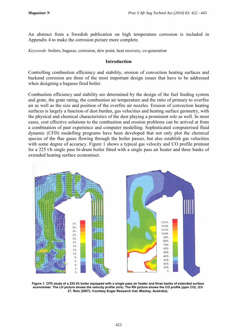
a combination of past experience and computer modelling. Sophisticated computerised fluid
dynamic (CFD) modelling programs have been developed that not only plot the chemical
species of the flue gases flowing through the boiler passes, but also establish gas velocities
with some degree of accuracy. Figure 1 shows a typical gas velocity and CO profile printout
for a 225 t/h single pass bi-drum boiler fitted with a single pass air heater and three banks of
extended heating surface economiser.
Figure 1: CFD study of a 225 t/h boiler equipped with a single pass air heater and three banks of extended surface economiser. The LH picture shows the velocity profile (m/s). The RH picture shows the CO profile (ppm CO). (Ch
27, Rein (2007); Courtesy Sugar Research Inst, Mackay, Australia).
Magasiner N Proc S Afr Sug Technol Ass (2010) 83: 422 - 443
423

This paper deals with the physics and chemistry of the remaining problem; i.e. backend
corrosion and the tools available to the designer and boiler operator to control corrosion.
Graphs and equations are included that apply to typical cane sugar industry operating
conditions. The graphs and equations can also be used to evaluate the potential for backend
corrosion to occur when burning other biomass fuels, such as woodwaste, which have similar
moisture and ash contents. Also included is a graph showing how, when mixed firing, the
H2SO4 ADP varies with the load carried on coal, the amount of sulphur in the fuels and the
amount of SO2 converted to SO3. Graphs are provided to show how final gas temperature
varies with economiser heating surface and to what extent efficiency can be improved by
reducing feed water temperature when an economiser is the last heat recovery surface in the
chain.
Backend corrosion physics and chemistry
A plot of the water vapour dew point for a range of bagasse compositions is shown in Figure
2. The concentration by volume of moisture in the flue gas when burning 46% moisture
bagasse having an ash content of 2% will be just over 26%. For 56% moisture bagasse with
an 8% ash content the moisture in the flue gas will be a little under 34%. These moisture
contents are about 3.5 to 5.0 times higher than those produced when burning coal.
Backend corrosion in bagasse fired boilers is caused by sulphuric and to a far lesser extent
hydrochloric acids condensing onto
heating surfaces that operate below their
respective ADPs. These hot acids are
concentrated and highly corrosive.
Corrosion rates are mainly a function of
the concentrations of sulphur and chlorine
in the fuels and the moisture
concentrations and excess air levels in the
flue gas.
The H2SO4 and HCl dew points are a
function of the partial pressures of the SO3,
HCl and water vapour in the flue gas. A
number of formulae are available to
determine the H2SO4 ADP, two of which
are used extensively. These were derived
by Verhoff and Banchero (1974) (equation
1; Appendix 1) and Okkes and Badger
(1987) (equation 2; Appendix 1).
There do not appear to be any definitive numbers for the conversion rate of SO2 to SO3 for
bagasse. The conversion rate for woodwaste appears to be about 2%. As wet woodwaste has
very similar combustion characteristics to bagasse it would appear that this figure may also
apply to bagasse. If so, the two formulae referred to above, within the range 1-3%, agree
closely.
Figure 2: Water dew point as a function of moisture in flue gas.
Water Dew Point
65
66
67
68
69
70
71
72
73
26 28 30 32 34
Moisture Concentration in Flue Gas (vol %)
Water Dew Point oC
Magasiner N Proc S Afr Sug Technol Ass (2010) 83: 422 - 443
424

Figure 3 plots the H2SO4 ADPs as
calculated by the Verhoff and Banchero
(1974) and the Okkes and Badger (1987)
methods.
To be able to use the above formulae one
must know the concentrations by volume of
water and SO2 vapour in the flue gas. These
figures are normally calculated from the
fuel’s ultimate analysis and the expected
excess O2 concentration. Figures 4 and 5
shortcut this procedure. Given fuel moisture
and ash content on a % by mass ‘as fired’
basis and sulphur in the fuel on a by mass
dry ash free % (DAF) basis, Figure 4 can be
used to determine the concentration of water
vapour and Figure 5 the concentration of
SO2 in the flue gas. Both these
concentrations are reported as percentages.
They can be converted to partial pressures
by multiplying them by 1.01325/100 to
arrive at the partial pressures at sea level,
0°C. The partial pressures must be corrected
for altitude and also take the suction in the
gas ducting into account. A suction of 2500
Pa will bring the ADP down by about 0.5°C. At higher altitudes (lower atmospheric pressure)
the dew points are lower.
Oxidation of S to SO2 takes place in the furnace at high temperatures. SO2 partially converts
Flue Gas Moisture - Bagasse
22
24
26
28
30
32
34
36
46 48 50 52 54 56
Fuel Moisture (mass %)
Concentration of H2O in Flue Gas (vol %)
2 % ash
8 % ash
5 % ash
3 % O2
5 % O2
Figure 4: Concentration of Moisture in Flue Gas as a function of Fuel Moisture, Ash Content and O2
Figure 5: Concentration of SO2 in Flue Gas as a function of Fuel Moisture, Sulphur (DAF) and O2
Flue Gas SO2 - Bagasse
0.000
0.002
0.004
0.006
0.008
0.010
0.012
0.014
0.016
0.018
0.020
46 48 50 52 54 56
Fuel Moisture (mass %)
Concentration of SO2 in Flue Gas (vol %)
0,200 S DAF
0,100 S DAF
0,050 S DAF
0,025 S DAF
3% O2
5% O
2
Figure 3: Comparison of Verhoff and Banchero (1974) and Okkes and Badger (1987) methods of determining
Acid Dew Points
Sulphuric Acid Dew Point
52 % Moist Fuel, 2 % Ash, 3 % O2
and 0.025 % S (DAF)
80
85
90
95
100
105
110
115
120
125
130
0 1 2 3 4 5
% SO2 Converted to SO
3
Acid Dew Point oC
V + B Method
O + B Method
Magasiner N Proc S Afr Sug Technol Ass (2010) 83: 422 - 443
425
to SO3 in the furnace, superheater and
convection passes. Catalysts can enhance the
reaction. It is well known that when burning
heavy fuels oils, Fe and V act as catalysts in
the superheater and convection passes.
The conversion of SO3 to H2SO4 starts at over
400°C and is completed by the time the gas
temperature has dropped to just below 176°C.
Table I schedules the percentage of SO3 that
converts to H2SO4 at a given temperature.
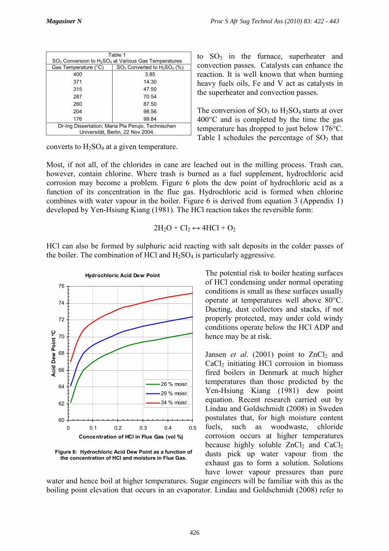
Most, if not all, of the chlorides in cane are leached out in the milling process. Trash can,
however, contain chlorine. Where trash is burned as a fuel supplement, hydrochloric acid
corrosion may become a problem. Figure 6 plots the dew point of hydrochloric acid as a
function of its concentration in the flue gas. Hydrochloric acid is formed when chlorine
combines with water vapour in the boiler. Figure 6 is derived from equation 3 (Appendix 1)
developed by Yen-Hsiung Kiang (1981). The HCl reaction takes the reversible form:
2H2O + Cl2 ↔ 4HCl + O2
HCl can also be formed by sulphuric acid reacting with salt deposits in the colder passes of
the boiler. The combination of HCl and H2SO4 is particularly aggressive.
The potential risk to boiler heating surfaces
of HCl condensing under normal operating
conditions is small as these surfaces usually
operate at temperatures well above 80°C.
Ducting, dust collectors and stacks, if not
properly protected, may under cold windy
conditions operate below the HCl ADP and
hence may be at risk.
Jansen et al. (2001) point to ZnCl2 and
CaCl2 initiating HCl corrosion in biomass
fired boilers in Denmark at much higher
temperatures than those predicted by the
Yen-Hsiung Kiang (1981) dew point
equation. Recent research carried out by
Lindau and Goldschmidt (2008) in Sweden
postulates that, for high moisture content
fuels, such as woodwaste, chloride
corrosion occurs at higher temperatures
because highly soluble ZnCl2 and CaCl2
dusts pick up water vapour from the
exhaust gas to form a solution. Solutions
have lower vapour pressures than pure
water and hence boil at higher temperatures. Sugar engineers will be familiar with this as the
boiling point elevation that occurs in an evaporator. Lindau and Goldschmidt (2008) refer to
Table 1 SO3 Conversion to H2SO4 at Various Gas Temperatures
Gas Temperature (°C) SO3 Converted to H2SO4 (%)
400 3.85
371 14.30
315 47.50
287 70.54
260 87.50
204 98.56
176 99.84
Dr-Ing Dissertation; Maria Pla Perujo, Technischen Universität, Berlin, 22 Nov 2004.
Figure 6: Hydrochloric Acid Dew Point as a function of the concentration of HCl and moisture in Flue Gas.
Hydrochloric Acid Dew Point
60
62
64
66
68
70
72
74
76
0 0.1 0.2 0.3 0.4 0.5
Concentration of HCl in Flue Gas (vol %)
Acid Dew Point oC
26 % moist
29 % moist
34 % moist
Magasiner N Proc S Afr Sug Technol Ass (2010) 83: 422 - 443
426

the phenomenon as the DRH (deliquescent relative humidity). This is the ratio of the partial
pressure of a salt solution to the partial pressure of pure water at a given temperature. The
DRH is always less than one. The lower it is the greater is the solubility of the salt.
Figure 7, taken from Lindau and Goldschmidt (2008), plots the DRH for ZnCl2 and CaCl2 and
the RH of exhaust gases having moisture contents of 15 and 25% against temperature. The
curves, when extrapolated, show that the dew point of a ZnCl2 solution will be about 128°C if
the RH of the gas is 15% and about 140°C if it is 25%. For a CaCl2 solution these figures are
about 95 and 110°C respectively. These authors go on to suggest from observations made on a
number of low pressure hot water woodfired boilers that corrosion is initiated in the presence
of these salts when the moisture content of the flue gas exceeds 22%. As flue gas moisture
when firing bagasse is between 26 and 34%, bagasse fired boilers are potentially at risk.
Burning coal, which can have a have a relatively high chlorine content, together with bagasse
may aggravate the problem.
As it is difficult to predict the HCl
concentration in the flue gas and as on-line
HCl corrosion does not usually occur
because the HCl ADP is much lower than
the H2SO4 ADP, the balance of this paper
deals largely with H2SO4 corrosion which,
in any event, is the dominant corrosion
mechanism. DRH corrosion can only be
dealt with on a case-by-case basis.
Coal can have a sulphur content about ten
times higher than that of bagasse but it
generates only about one third to half as
much flue gas moisture. When burning the
fuels together the high sulphur content of
the coal in combination with the high
moisture content of the bagasse elevates the
H2SO4 ADP. The ADP of coal is usually
higher than that of bagasse but it can be
lower if the sulphur content of the bagasse
is more than about 20 % that of the coal.
When the two fuels are burned together the
ADP is usually higher than it would be for
either of them burned singly.
The concentration of moisture in the flue gas when burning coal can be obtained from Figure
8. The graph takes cognisance of the relatively large contribution made by the fuel’s hydrogen
content. This correction is incorporated automatically in the bagasse graphs in Figures 4 and
5.
Figure 9 plots the concentration of SO2 generated when burning coal as a function of the total
Figure 7. DRH for CaCl2 and ZnCl2 blue curve = RH of flue gas with 15 % H2O; orange curve = RH of flue gas with 25 % H2O – Courtesy Lindau and Goldschmidt
Relative Humidity of Water Vapour
and DRH of ZnCl2 and CaCl2 vs Temperature
0.0
0.1
0.2
0.3
0.4
0.5
0.6
50 70 90 110 130 150
Temperature OC
RH and DRH
RH 25% H2O
RH 15% H2O
DRH ZnCl2
DRH CaCl2
Magasiner N Proc S Afr Sug Technol Ass (2010) 83: 422 - 443
427

concentration of moisture (free, inherent and that arising from the oxidation of H2 to H2O).
Whereas fuel moisture is the input to Figure 5, the moisture concentration read off Figure 8 is
the input to Figure 9.
As with bagasse there do not appear to be reliable figures for the conversion rate of SO2 to
SO3 for coal burned on a spreader stoker. Srivastava et al. (2002) suggest that for pulverised
coal fired boilers about 0.1 to 0,65% of the SO2 generated is converted to SO3. The
conversion rate is heavily dependent on the amount of excess air used and, as mentioned
above, is also enhanced by the catalytic action of Fe and V in the superheater and convection
passes.
Figure 10 shows how, when mixed firing, H2SO4 ADP varies as the percentage of load carried
on coal increases. The curves are based on a 52% moisture, 2% ash bagasse having a sulphur
content on a DAF basis of 0.05% (0.023% S ‘as fired’). The coal analysis is taken from
Magasiner (2001), Table 2, with sulphur content varying from 0.3 to 2.0% whilst keeping the
moisture and ash contents constant. For bagasse the SO2 to SO3 conversion rate is 2,0 % and
for coal it is 0,5%.. ‘As fired’ sulphur levels in bagasse are usually around 0.01 to 0.04%. In
Florida, where there is a high concentration of H2S in the ground water, the S in bagasse can
be over 0.1%.
For coal with sulphur levels higher than about 0,7 %, as load increases, the ADP usually
rises. For these higher sulphur contents the ADP reaches a maximum when the load carried on
coal is about 80 to 90% of the total load on the boiler, after which it drops rapidly down to the
ADP of the coal itself.
In the past the author has argued against mixed firing of bagasse and coal in order to minimise
the risk of forming unmanageable clinkers on the grate. It is clear from Figure 10 that mixed
firing should be carried out with due regard to the sulphur levels in the fuels as well.
Figure 8: Concentration of moisture in flue gas as a function of fuel moisture, H2 and O2.
Flue Gas Moisture - Coal
6
7
8
9
10
11
12
13
2 3 4 5 6 7 8 9 10 11 12 13 14 15 16
Fuel Moisture (mass %)
Concentration of H2O in Flue Gas (vol %)
6% H2
5% H2
4% H2
3% H2
3% O2
5% O
2
Figure 9: Concentration of SO2 in flue gas as a function of moisture concentration (including H2 generated
moisture), S and O2.
Flue Gas SO2 - Coal
0.00
0.02
0.04
0.06
0.08
0.10
0.12
0.14
0.16
0.18
0.20
2 3 4 5 6 7 8 9 10 11 12 13 14 15 16
Moisture Concentration in Flue Gas (vol %)
Concentration of SO2 in Flue Gas (vol %)
2% S
1% S
3% O2
5% O2
Magasiner N Proc S Afr Sug Technol Ass (2010) 83: 422 - 443
428

A program for calculating the ADP when
mixed firing is included in Appendix 2.
Some of the sulphur and chlorine in the
fuel can be bound with the ash and fly ash
during the combustion process. The above
calculations are based on the conservative
assumption that all the sulphur and
chlorine in the fuel reports to the gas
phase.
A bagasse ‘as fired’ sulphur content of
0.023% (DAF 0.05%) may not seem much
when compared with the sulphur contents
of fossil fuels such as coal and oil. But, if
dew point conditions occur in an air heater,
metal loss of the affected tubes can vary
from 20 to 85%, or more, in five years.
Metal temperatures
Low temperature corrosion takes place
when metal surface temperatures drop
below the ADP. These surfaces include the
economiser, air heater, exhaust gas
ducting, dust collecting equipment and chimney. All these surfaces are exposed to flue gas on
one side and either water or air on the other. The boiler pressure parts of hot water and steam
boilers operating at less than 3 bar may also be subject to corrosion.
The metal temperature is dependent on the temperature
of the fluids, the heat transfer coefficients on either
side of the metal and to a far lesser degree the heat
transfer coefficient of the metal itself. Figure 11
illustrates the temperature gradient through a metal
barrier such as an air heater or economiser tube or gas
ducting.
For practical purposes it is sufficiently accurate to
assume there is no temperature gradient through an air
heater’s tube wall. It is normally less than 1.5°C. The
average metal temperature can be calculated from the
equation:
Heat transferred from gas side = Heat transferred to fluid side 1
i.e. kg·(Tg -Tm) = ka·(Tm -Ta) 2
Figure 11: Temperature gradient through a metal barrier such as an air heater or economiser tube or a gas
duct.
Gas side boundary layer
Fluid side boundary layer
Scale
Figure 10: Chart showing how, when mixed firing, the sulphuric acid dew point varies as the proportion of load
carried on coal increases.
110
115
120
125
130
135
140
145
150
0 20 40 60 80 100
Acid Dew Point oC
Coal Firing %
Bagasse/Coal Fired H2SO4 Dew Point Verhoff and Banchero Method
% S in Coal "as fired"
0,30 %1,00 %1,50 %
Coal SO2 to SO3Conversion
0,5 %1,0 %2,0 %
Magasiner N Proc S Afr Sug Technol Ass (2010) 83: 422 - 443
429

and hence Tm = (Tg·kg + Ta·ka) 3
(ka + kg)
The overall heat transfer coefficient can be calculated from the relationship:
1/koverall = 1/kg + 1/ka 4
where:
Ka is the air side convection heat transfer coefficient W/m2·°C
kg is the gas side convection heat transfer coefficient W/m2·°C
koverall is the overall heat transfer coefficient W/m2·°C
Tm is the average metal temperature °C
Ta is the air temperature °C
Tg is the gas temperature °C
Air heaters can be designed to have gas flowing through and air over the tubes or vice versa.
To minimise erosion, cane sugar boiler air heaters usually have the gas flowing through the
tubes.
In well designed air heaters the metal temperature is a little below or about halfway between
the gas and air temperatures. The heat transfer coefficients on both the air and gas sides of an
air heater range between 45 and 65 W/m2·°C. Because the outside area of a tube is larger than
its inside area, for these figures to be used in equation 2, they need to be referred to the same
side of the tube.
To achieve similar coefficients on both sides and hence a metal temperature about midway
between the gas and air temperatures, gas velocities of about 20 to 25 m/s and air velocities of
about 4 to 5 m/s are required for a diagonally pitched 63.5 mm diameter tube array. While
these high gas velocities will lead to severe erosion if the gas flows over the tubes, they are
acceptable for gas flowing through a tube. To avoid localised erosion if the gas inlet ducting
design leads to dust channelling, it is sometimes advisable to insert replaceable hardened steel
or ceramic inserts into the mouths of the tubes. These inserts measure 1.5 to 3 times the tube
diameter in length.
For a plain tube economiser the gas side heat transfer coefficient is about 1.5 times higher
than it is for an air heater. On the water side the heat transfer coefficient is in the region of
about 15 000 W/m2·°C. Economiser average metal temperatures are therefore close to the
water temperature (usually less than 1°C higher than the water temperature at the cold end) so
the best way of controlling the metal temperature and hence corrosion is to pre-heat the feed
water. The temperature gradient across the tube is usually less than 1°C.
In the author’s experience over the past two decades mild steel finned tube economisers
outperform plain tube economisers from an overall cost, erosion and corrosion point of view.
Acid condensate on metal surfaces when operating below the dew point acts like flypaper
trapping dust and char. The gas side of cast iron finned tube economisers which were used
extensively until the 1980s and which are more corrosion resistant than finned mild steel units
Magasiner N Proc S Afr Sug Technol Ass (2010) 83: 422 - 443
430
often choked because they were fed with water at 80 to 105°C; i.e. at temperatures which
were often below the dew point; hence the need for feedwater heaters.
Heat recovery plant arrangements
Conventional mills
From the late 1950s most new boilers installed in the South African cane sugar industry were
designed to operate at about 30 bar (g). This limit was set to obviate the need for sophisticated
boiler water treatment regimes and water quality controls. Now, a typical 30 bar boiler
installed in a conventional thermally balanced cane sugar factory will include a water cooled
furnace, a superheater, a convection bank and an air heater. The air heater can be arranged
either as a parallel or contra flow heat exchanger.
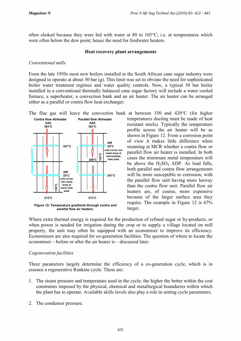
The flue gas will leave the convection bank at between 350 and 420°C (for higher
temperatures ducting must be made of heat
resistant steels). Typically the temperature
profile across the air heater will be as
shown in Figure 12. From a corrosion point
of view it makes little difference when
steaming at MCR whether a contra flow or
parallel flow air heater is installed. In both
cases the minimum metal temperature will
be above the H2SO4 ADP. As load falls,
both parallel and contra flow arrangements
will be more susceptible to corrosion, with
the parallel flow unit having more leeway
than the contra flow unit. Parallel flow air
heaters are, of course, more expensive
because of the larger surface area they
require. The example in Figure 12 is 67%
larger.
Where extra thermal energy is required for the production of refined sugar or by-products, or
when power is needed for irrigation during the crop or to supply a village located on mill
property, the unit may often be equipped with an economiser to improve its efficiency.
Economisers are also required for co-generation facilities. The question of where to locate the
economiser – before or after the air heater is – discussed later.
Cogeneration facilities
Three parameters largely determine the efficiency of a co-generation cycle, which is in
essence a regenerative Rankine cycle. These are:
1. The steam pressure and temperature used in the cycle; the higher the better within the cost
constraints imposed by the physical, chemical and metallurgical boundaries within which
the plant has to operate. Available skills levels also play a role in setting cycle parameters.
2. The condenser pressure.
Figure 12: Temperature gradients through contra and parallel flow air heaters.
Contra flow Airheater Parallel flow AirheaterGAS GAS
363°C 363°C
AIR
247°C 25°C
288°C
AIR
25°C 247°C
273°C 273°C
cold corner min
metal temp at
intermediate
tube plate
cold corner
min metal
temp at
lower tube
plate136°C
152°C
Magasiner N Proc S Afr Sug Technol Ass (2010) 83: 422 - 443
431

3. The amount of steam that can be bled off from the turbine to do useful work prior to the
condenser. In an export co-generation facility hosting a cane sugar factory, steam is
mainly bled to supply the factory’s process needs and for feed water and combustion air
heating.
Export co-generation cycles typically operate at turbine inlet stop valve conditions of about
43, 60 or 80 bar (g). Allowing a 2 bar pipeline pressure drop between the boiler and turbine
and a pressure drop of about 7% of the boiler stop valve pressure across the superheater, the
saturation temperatures in the boiler are 241°C for the 30 bar cycle and 262, 282 and 302°C
for the 43, 60 and 80 bar cycles respectively.
Magasiner (1996) deals with the effect that increasing cycle pressure has on boiler heating
surface configuration. The author shows that a number of design changes are required in order
to optimise boiler performance for the higher pressures required for co-generation. First, more
furnace heating surface and hence a taller furnace is required to compensate for the higher
saturation temperature and to make space for the superheater radiant heating surface needed
for the higher steam temperature. Then, because the saturation temperature is higher, the gas
temperature leaving the convection pass is higher. This all results in the back end design
being dominated by an economiser rather than an air heater.
The reason for the switch in dominance is as follows. The maximum air temperature leaving
the air heater is dictated by the maximum allowable air temperature that can be tolerated by
the combustion equipment and, sometimes even more importantly, by the clinkering
characteristics of the fuel. Increasing the gas temperature to the air heater makes the air heater
work harder. So much so that at a pressure of 62 bar a single pass air heater is able to do about
the same amount of work as a two pass unit operating in conjunction with a 30 bar boiler. At
82 bar it is debateable whether a commercial case for a gas/air air heater can be made at all.
From the power cycle efficiency point of view, equipping the boiler with an economiser and a
steam heated air heater using steam bled from the turbine is often the optimum solution.
Table 2 schedules the anticipated performance of the backend of a typical 200 t/h, 62 bar
bagasse fired co-generation boiler. The unit has been sized to operate with feed at 130°C to
ensure that the economiser metal temperature is above the H2SO4 ADP when burning bagasse
having a high (0.1%) sulphur content. This temperature can be obtained by operating the de-
aerator at 2.7 bar, or by interposing a feed water heater between a de-aerator operating at
105°C and the economiser. In both cases steam bled from the turbine can be used as a
hearting medium for the de-aerators and the feed water heater.
Six different plant arrangements are scheduled. Three investigate plant performance with the
economiser placed ahead of the air heater and three with the air heater placed ahead of the
economiser.
Placing the economiser ahead of the air heater maximises the temperature differences between
sources and sinks and hence the potentials driving heat transfer between flue gas and heated
fluid: i.e. feed water at 130°C and air at 25°C. However, with this arrangement the air heater
is far more susceptible to corrosion.
Magasiner N Proc S Afr Sug Technol Ass (2010) 83: 422 - 443
432

In all cases the heat recovery plant has been sized to bring the final gas temperature down to
177°C when steaming at MCR. At lower loads the final gas temperature depends on plant
configuration and is, therefore, not necessarily always the same for all arrangements. The
performance figures are based on burning bagasse having a moisture content of 52 % and an
ash content of 2%. The calculations include the variation in excess air level with primary air
temperature as shown in Appendix 3. These corrections are relatively minor. The primary air
temperature is limited to a maximum of 250°C to allow for operation with a continuous ash
discharge stoker using ‘HS Meehanite’ or equal cast iron grate bars.
The six arrangements are:
A. Economiser followed by a two pass parallel flow air heater. With this arrangement the
economiser is 64% as big as the one included in arrangement F (base case) and the air
heater is over 50% bigger. This is because it operates in a cooler environment where the
temperature difference between gas and air is lower.
B. Economiser followed by a two pass contra flow air heater. The economiser in this instance
is identical to the one included in arrangement A but, because the air heater is a contra
flow rather than a parallel flow unit, it is only 96% as big as the one included in
arrangement F.
A B C D E F
Load
Economiser
with
Parallel Flow
A/H
Economiser
with
Contra Flow
A/H
Economiser
with
Contra Flow
A/H (same
heating
surface
geometry as
for A)
Load
Parallel Flow
A/H
with
Economiser
Contra Flow
A/H
with
Economiser
Single Pass
A/H
with
Economiser
100% Economiser water inlet 130 130 130 °C 100% Air through air heater 65 65 65 °C
Economiser water outlet 220 220 220 °C Air heater gas inlet 392 392 392 °C
Economiser gas inlet 393 393 392 °C Air heater gas outlet 303 303 303 °C
Economiser gas outlet 236 236 248 °C Air temp in 25 25 25 °C
Minimum metal temp 131 131 131 °C Air temp out 247 247 247 °C
∆∆∆∆Tg/∆∆∆∆Tw 1.74 1.74 1.60 Minimum metal temp 142 127 160 °C
Saturation temp 282 282 282 °C ∆∆∆∆Tg/∆∆∆∆Ta 0.40 0.40 0.40
Relative heating surface 0.64 0.64 0.54 Relative heating surface 1.03 0.79 1.00
Air through air heater 65 65 65 % Economiser water inlet 130 130 130 °C
Air heater gas inlet 234 234 246 °C Economiser water outlet 200 200 200 °C
Air heater gas outlet 177 177 177 °C Economiser gas inlet 303 302 302 °C
Air temp in 25 25 25 °C Economiser gas outlet 177 177 177 °C
Air temp out 160 160 190 °C Minimum metal temp 131 131 131 °C
Minimum metal temp 102 92 101 °C ∆∆∆∆Tg/∆∆∆∆Tw 1.80 1.78 1.79
∆∆∆∆Tg/∆∆∆∆Ta 0.42 0.42 0.42 Saturation temp 282 282 282 °C
Relative heating surface 1.51 0.96 1.51 Relative heating surface 1.00 1.00 1.00 %
Boiler efficiency 67.5 67.5 66.6 % Boiler efficiency 67.6 67.6 67.6 %
Relative power consumption 1.6 1.8 1.4 Relative power consumption 2.1 2.7 1.0
60% Economiser water inlet 130 130 130 °C 60% Air through air heater 68 68 68 %
Economiser water outlet 213 213 215 °C Air heater gas inlet 346 346 346 °C
Economiser gas inlet 346 346 346 °C Air heater gas outlet 261 259 259 °C
Economiser gas outlet 206 206 206 °C Air temp in 25 25 25 °C
Minimum metal temp 131 131 131 °C Air temp out 219 223 223 °C
∆∆∆∆Tg/∆∆∆∆Tw 1.68 1.68 1.66 Minimum metal temp 114 102 130 °C
Saturation temp 282 282 282 °C ∆∆∆∆Tg/∆∆∆∆Ta 0.44 0.44 0.44
Air through air heater 68 68 68 % Economiser water inlet 130 130 130 °C
Air heater gas inlet 205 205 205 °C Economiser water outlet 189 188 188 °C
Air heater gas outlet 154 150 160 °C Economiser gas inlet 261 259 259 °C
Air temp in 25 25 25 °C Economiser gas outlet 160 160 160 °C
Air temp out 143 143 123 °C Minimum metal temp 131 131 131 °C
Minimum metal temp 84 75 87 °C ∆∆∆∆Tg/∆∆∆∆Tw 1.71 1.70 1.70
∆∆∆∆Tg/∆∆∆∆Ta 0.43 0.47 0.46 Saturation temp 282 282 282 °C
Boiler efficiency 68.8 69.1 69.1 % Boiler efficiency 68.6 68.6 68.6 %
Boiler with Economiser followed by an Air Heater
TABLE 2 - Back End Arrangements - Comparison Based on Constant MCR Final Gas Temperature
Boiler with Air Heater followed by an Economiser
Magasiner N Proc S Afr Sug Technol Ass (2010) 83: 422 - 443
433

C. Economiser followed by a two pass contra flow air heater having the same physical
dimensions as the air heater included in arrangement A. The economiser in this
arrangement is less expensive, being only 54% as big as the one included in arrangement
F.
D. Two pass parallel flow air heater followed by an economiser. In this case the air heater is
just a little larger than the one included in arrangement F. The economiser is the same size
but over twice as much fan power is required by the heat recovery plant than is required
by arrangement F.
E. Two pass contra flow air heater followed by an economiser. This arrangement includes
the same economiser as is used in arrangement D. The air heater is smaller because of the
contra flow rather than parallel flow configuration. Nearly 2.75 times more fan power is
required by the heat recovery plant than is required by arrangement F.
F. Single pass air heater followed by an economiser. This is the base case. Here again the
economiser is the same size as that used in arrangement D, although the air heater is a
little smaller.
Arrangements D, E and F are able to provide air at higher temperatures than arrangements A,
B and C. This means that boilers equipped with D, E or F will have lower unburnt losses and
combustion will be more stable. This is reflected in the efficiencies they are able to achieve.
The Verhoff and Banchero (1974) equation calculates the H2SO4 ADP of 52% moisture
bagasse having a DAF sulphur content of 0.1% at about 129°C (for a DAF content of 0.01% it
is about 110°C). This is much higher than the calculated minimum metal temperatures that
arrangements A, B or C can achieve. For the ADP to be higher than 102°C, i.e. higher than
the minimum metal temperatures for arrangements A and C, the maximum sulphur content
may not exceed 0.002%. Placing the air heater after the economiser when burning most
bagasse types is therefore not practical.
Because backend arrangements D and E need so much more fan power, they are not as viable
commercially as arrangement F.
At 60% load the minimum metal temperature of arrangement E (102°C) is too low for all but
those fuels having a very low DAF sulphur level. With arrangement F having about the same
heating surface as arrangement D but being able to operate with a minimum metal
temperature of at least 130°C over an operating range of 60 to 100% MCR, and requiring only
about half as much power, F is clearly the best possible arrangement.
Notes on improving boiler and cycle efficiency
The efficiency of a boiler with air heater up front can be improved by adding extra
economiser heating surface. The improvement for a 52% moisture, 2% ash fuel is illustrated
in Figure 13. It is up to the designer together with the purchaser to do the cost/benefit studies
to determine the extent of heat recovery surface to install. When doing this exercise the
change in fan power consumption as a result of the change in heating surface must be taken in
to account.
Magasiner N Proc S Afr Sug Technol Ass (2010) 83: 422 - 443
434

The efficiency can also be improved by reducing the feed water temperature provided the
metal temperature is not allowed to drop below the H2SO4 ADP. Figure 14 typically
illustrates how final gas temperature drops as feed water temperature is reduced and how this
impacts on efficiency for a boiler burning bagasse having a moisture content of 52% and an
ash content of 2%.
As an alternative to fitting an economiser,
making the air heater work harder by
passing 100% of the combustion air
through it may in a conventional mill
sometimes be the better commercial
option. This arrangement reduces the final
gas temperature by about 20°C rather than
the ~125°C that can be obtained from an
economiser. The gain in efficiency with
this arrangement is, unfortunately, often
largely offset by the extra power required
to drive the overfire air fan (Magasiner
1974).
In the above examples, where the
economiser is placed after the air heater,
the water temperature leaving the
economiser at 200°C is well below boiling
point (282°C). To avoid steaming at MCR
the water leaving temperature should be
about 30°C lower than the boiling point.
This leaves room for enhancing the efficiency
of the power cycle by bleeding more steam
from the turbine into an economiser inter-
bank feed water heater. By placing this heater
between banks rather than at the inlet to the
economiser, the minimum sink temperature;
i.e. the feed water temperature can be kept at
the required level above the H2SO4 ADP thus
maintaining the temperature potential between
flue gas and water and hence the possibility of
achieving optimum boiler efficiency.
General notes on heat recovery plant
performance
An interesting feature of two pass parallel
flow air heaters is that most of the work is
done in the first pass and only a small
fraction is done in the second. From Figure
12, work done in first pass ~ (363 – 288)/(363
– 273) x 100 = 83%.
Figure 14: Affect on final gas temperature and efficiency as a function of feed water temperature
Feed Water Temp vs
Final Gas Temp & Efficiency
140
150
160
170
180
190
105 110 115 120 125 130
Feed Water Temperature oC
Final Gas Temperature oC
99
100
101
102
103
104
Relative Efficiency
Final Gas Temp (MCR)
Final Gas Temp (60% MCR)
Relative Efficiency (MCR)
Relative Eff iciency (60% MCR)
Figure 13. Effect of increasing economiser heating surface on the performance of a boiler firing 52%
moisture, 2% ash bagasse.
Final Gas Temp vs
Economiser Relative Heating Surface &
Efficiency
120
130
140
150
160
170
180
190
200
210
220
0.5 1 1.5 2 2.5 3
Economiser Relative Heating Surface
Final Gas Temp oC
95
96
97
98
99
100
101
102
103
104
105
Relative Efficiency
Feed Water Temp
Final Gas Temp
Relative Eff iciency
Magasiner N Proc S Afr Sug Technol Ass (2010) 83: 422 - 443
435

The air heater performance figures shown in Figure 12 and Table 2 assume that at MCR 65%
of the total combustion air required is delivered as primary air to the grate with the balance
being delivered as cold overfire air. At 60% load, more excess air is used. The O2 level can be
as much as 1% higher. Table 2 figures take cognisance of this.
How air heater metal temperature varies with load
From Table 2 it is clear that gas temperature falls as load falls which in turn means that metal
temperature, which is a function of gas temperature, falls as well. In fact, air heater metal
temperature falls more rapidly than would be anticipated from a simple analysis of the fall in
gas temperature.
The reason for this is as follows. In cane sugar industry boilers gas normally flows through
the tubes and air flows over the tubes. For gas flowing through the tubes the heat transfer
coefficient kg is ~Vg0.8 and for air flowing over the tubes the heat transfer coefficient is ~Va
0.6
where Vg is the gas velocity through the tubes and Va the air velocity over the tubes. As load
falls, therefore, the gas side coefficient falls off more rapidly than the air side coefficient,
which in turn means that with falling load metal temperature is lower than anticipated and
hence the corrosion problem is aggravated. (If velocities drop by half, Vg0.8 = 0.574 times and
Va0.6 = 0.660 times the previous values.)
Backend plant arrangements
After extracting as much heat as is economically feasible from the flue gas it is exhausted
through a dust collector, an induced draft fan and a chimney. Each of these components as
well as the ducting carrying the flue gas is vulnerable to corrosion. Where a wet scrubber is
used to collect dust the exhaust from the scrubber will be saturated with water vapour. The
water used for scrubbing is usually dosed with an alkali in sufficient quantity to ensure that
the gases and fluids leaving the scrubber are not corrosive.
With dry collecting systems the flue gas temperature from the heat recovery plant is usually
high enough to ensure that the ducting, collector, ID fan and chimney operate above the dew
point without lagging. In windy and/or colder areas such as Eston, Dalton and Noodsberg
where ambient air temperatures are sometimes fairly low, measures should be taken to protect
these components.
Conclusions
Corrosion is experienced in a boiler whilst it is in operation wherever metal temperatures drop
below the ADP of the flue gas. The H2SO4 ADP is largely dependent on the sulphur content
of the fuel which oxidises to SO2 during the combustion process and on the proportion of SO2
that converts to SO3. SO3 in turn converts to H2SO4 as the gas cools down from 400°C.
Chlorine in the fuel can convert to HCl during the combustion process. While the dew point
of HCl is lower than that of H2SO4, recent studies show that chlorine can under certain
circumstance be aggressive at higher than HCl’s normal ADP if zinc and calcium are also
present.
Both the H2SO4 and HCl ADPs are dependent on the concentrations by volume of water
Magasiner N Proc S Afr Sug Technol Ass (2010) 83: 422 - 443
436

vapour, SO2 and HCl in the flue gas. Graphs and formulae provided in this paper enable the
boiler designer and boiler operator to determine the dew points of both these acids.
Air heater and economiser corrosion occurs when the temperature of the metal from which
these components are made drops below the ADP. The gas temperature can be well above the
dew point for this phenomenon to occur. The phenomenon is analogous to one’s spectacles
misting over when getting out of a cold air conditioned car into a hot, humid environment.
With export co-generation becoming more attractive, more boilers are being installed to
operate at higher pressures. The higher saturation temperatures associated with these
pressures reduces the effectiveness of the boiler radiant and convective passes, thus requiring
the heat recovery or backend of the unit to work harder. The paper shows that as pressure
rises a single pass air heater placed upstream of the economiser provides the best corrosion
resistant solution. It also shows that with gas through tube air heaters, as load falls dew point
falls faster than can be expected because of the way in which heat transfer coefficients vary
with load. At higher pressures a steam heated air heater is often the best solution. (Warning:
Take precautions at the design stage to ensure that airborne dust does not clog the air side of
these units.)
While careful plant design can minimise the risk of corrosion occurring, operators can also
prevent corrosion by ensuring that in the case of economisers feed water heaters are used
correctly to preheat the feed water and in the case of air heaters, air is bypassed around the air
heater to maintain metal temperatures above the ADP. Temperature probes should be inserted
into economiser and air heater tubes where the lowest metal temperatures are expected in
order to monitor the temperatures of these components.
By being aware of the ADPs of the fuels being burned the operator can adjust the feed water
temperature or air heater bypass, if applicable, to maximise plant efficiency. For economisers
it is best to use a feed water temperature at least 5°C higher than the calculated ADP and in
the case of an air heater, a metal temperature at least 10°C higher. Air heaters require higher
margins because their metal temperatures fluctuate over much larger ranges. Having
established a theoretical dew point it is very important to regularly inspect the areas where
corrosion can be expected to occur in order to verify that the predictions are valid. Having
established an inspection regime, the operator can ‘fine tune’ the feed water or, if applicable,
the air heater metal temperature to achieve best results. Calculated ADPs should be revisited
whenever fuel qualities change.
In geographical areas where windy and/or colder ambient air temperatures are experienced
stack metal temperatures should also be monitored.
To complete the corrosion picture, Appendix 4 includes a note on high temperature corrosion.
Acknowledgement
The author thanks Dr John de Kock for reviewing this paper and for his advice regarding the
physical chemistry.
Magasiner N Proc S Afr Sug Technol Ass (2010) 83: 422 - 443
437

REFERENCES
Jensen JP, Fenger LD and Henriksen N (2001). Cold-end corrosion in biomass and waste incineration
plants. PowerPlant Chemistry 2001: 3(8).
Lindau L and Goldschimdt B (2008). Low temperature corrosion in bark fueled, small boilers.
Varmeforsk Services AB M9-835.
Magasiner N (1974). Boiler plant as an integral part of a cane sugar factory. Proc Int Soc Sug Cane
Technol 15: 1642-1679
Magasiner N (1996). Bagasse-fired boiler design with reference to co-generation. Int Sug J Vol
XCVIII, No. 1167: 100-109.
Magasiner N, van Alphen C, Inkson MB and Misplon BJ (2001). Characterising fuels for biomass-
coal fired co-generation. Proc S Afr Sug Technol Ass 75: 282-291.
Okkes AG and Badger BV (1987). Get acid dew point of flue gases. Hydrocarbon Proc 66(7): 53.
Rein P (2007). Cane Sugar Engineering. Verlag Dr Albert Bartens KG, Berlin, ISBN 978-3-87040-
110-8; Ch 27, Figures 27.11 and 27.12.
Srivastava RK, Miller CA, Erickson C.and Jambhekar R (2002). Emissions of sulphur trioxide from
caol-fired power plants. POWER-Gen Int 2002: 5-9.
Verhoff FH. and Banchero JT (1974). Predicting dew points of flue gases. Chem Eng Progr 70(8): 71.
Yen-Hsiung Kiang (1981). Predicting dew points of acid gasses. Chem Eng Feb 9.
Magasiner N Proc S Afr Sug Technol Ass (2010) 83: 422 - 443
438

Appendix 1 – Formulae
Sulphuric Acid Dew Point (Verhoff and Banchero, 1974)
1000/TdpS = 2.276-0.02943*ln(PH2O)-0.0858*ln(PSO3)+0.0062*ln(PH2O)*ln(PSO3) (1)
where:
TdpS is the H2SO4 dew point temperature in °K
P is the partial pressure in mm Hg.
Sulphuric Acid Dew Point (Okkes and Badger, 1987)
Tdp = 203.25+27.6*log10(PH2O)+10.83*log10(PSO3)+1.06*(log(PSO3)+8)
2.19 (2)
where:
TdpS is the H2SO4 dew point temperature in °C
P is the partial pressure in atm.
Hydrochloric Acid Dew Point (Yen-Hsiung Kiang, 1981)
1000/TdpH = 3.7368-0.1519*ln(PH2O)-0.0326*ln(PHCl)+0.00269ln*(PH2O)*ln(PHCl) (3)
where:
TdpH is the HCl dew point temperature in °K
P is the partial pressure in mm Hg.
Continued…..
Magasiner N Proc S Afr Sug Technol Ass (2010) 83: 422 - 443
439
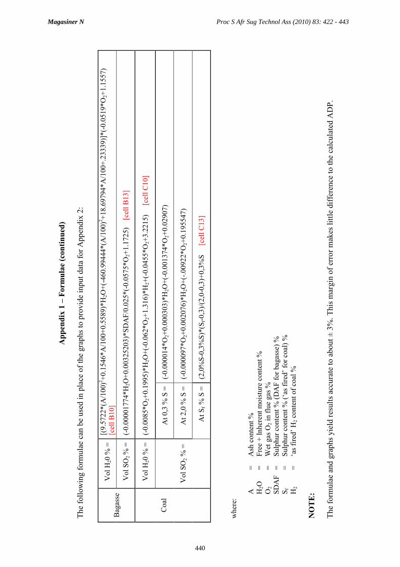
Appendix 1 – Formulae (continued)
The following form
ulae can be used in place of the graphs to provide input data for Appendix 2:
where:
A
= Ash content %
H
2O
= Free + Inherent moisture content %
O
2
= W
et gas O
2 in flue gas %
SDAF = Sulphur content % (DAF for bagasse) %
Sf
= Sulphur content % (‘as fired’ for coal) %
H
2
= ‘as fired’ H
2 content of coal %
NOTE:
The form
ulae and graphs yield results accurate to about ± 3%. This m
argin of error makes little difference to the calculated ADP.
Bagasse
Vol H
20 %
= [(9.5722*(A
/100)2+0.1546*A/100+0.5589)*H
2O+(-460.99444*(A
/100)2+18.69794*A/100+.23339)]*(-0.0519*O
2+1.1557)
[cell B10]
Vol SO
2 % = (-0.00001774*H
2O+0.00325203)*SDAF/0.025*(-0.0575*O
2+1.1725) [cell B13]
Coal
Vol H
20 %
= (-0.0085*O
2+0.1995)*H
2O+(-0.062*O
2+1.316)*H
2+(-0.0455*O
2+3.2215) [cell C10]
Vol SO
2 %
=
At 0,3 %
S = (-0.000014*O
2+0.000303)*H
2O+(-0.001374*O
2+0.02907)
At 2,0 %
S = (-0.000097*O
2+0.002076)*H
2O+(-.00922*O
2+0.195547)
At Sf % S = (2,0%S-0,3%S)*(S
f-0,3)/(2,0-0,3)+0,3%S [cell C13]
Magasiner N Proc S Afr Sug Technol Ass (2010) 83: 422 - 443
440

Appendix 2 – Quick method of calculating acid dew point when dual firing.
A B C D E
1
2 ENTER Proportion by mass of bagasse burned 0.9 =(1-B2)
3 ENTER % O2 in wet exhaust gas 5.0 %
4 Bagasse Coal Comments
5 ENTER fuel H2O content (inherent+free) (M) % 52.0 5.0 % From fuel analysis
6 ENTER fuel H2 content (H2) % 3.5 % From fuel analysis
7 ENTER fuel S content (S) % 0.05 0.85 % For Bagasse "DAF"; For Coal "as fired"
8 ENTER fuel ash content(A) % 2.0 12.8 % From fuel analysis
9 ENTER fuel brix content (s) % 1.6 From fuel analysis
10 ENTER volume of H2O in flue gases 26.7 7.3 % From Figs 4 and 8
11 "As fired" volume of H2O in flue gases =B10*B2 =C10*C2 %
12 Volume of H2O in mixture of flue gases =B11+C11 %
13 ENTER volume of SO2 in flue gases 0.0041 0.0683 % From Figs 5 and 9
14 "As fired" volume of SO2 in flue gases =B13*B2 =C13*C2 %
15 ENTER % mass S02 converted to SO3 2.00 0.50 %Assumes 2,0 % SO2 converted to SO3 on bagasse
Assumes 0,5 % SO2 converted to SO3 on coal
16 "As fired" volume of SO2 converted to SO3 =B14*B15*64/80/100 =C14*C15*64/80/100 %SO2/SO3 conversion is on a mass basis hence the
need to multiply by ratio of mol masses; i.e. 64/80
17 Volume of SO2 converted to SO3 in flue gases B16+C16 %
18 ENTER GCV of coal bagasse GCV equation 26,620 kJ/kgFor bagasse : =196.05·(100 -M - A) - 31.14·s
For coal : From fuel analysis
19 ENTER GCV efficiency 63.4 78.6 %From Rein (2007) Figs 27.4 and 27.5 respectively.
Say final gas temeperature = 240oC and O2 = 3%
20 Effective GCV =B18*B19/100 =C18*C19/100 kJ/kg
21 "as fired" GCV of mixture =(B20*B2)+(C20*C2) kJ/kg
22 Load on each fuel =B20/C21*B2*100 =(100-B22) %Use "Goal Seek" to obtain desired load on coal.
Vary cell B2
23
24
25 Volume of H2O in mixture of flue gases =C12 % vol in gas
26 Wet Gas O2 =B3 % vol in gas
27 Volume of SO2 converted to SO3 in flue gases =C17 % vol in gas
28 ENTER site Altitude 80 masl
29 Bara pressure bara pres equation bar
30 ENTER gas pressure in duct -2,500 Pa
31 =B30/100000 bar
32 Bara pressure in duct =B29+B31 bar
33 PH2O =B25*B32*760/100 mm Hg
34 =LN(B33) ln(PH20)
35 PSO3 =B27*B32*760/100 mm Hg
36 =LN(B35) ln(PSO3)
37 1000/Tdp V + B equation
38 Tdp =1000/B38oK
39 ACID DEW POINT TEMP Tdp =B39-273.15oC
ENTER Proportion by mass of bagasse burned 0.90 0.10
ENTER % O2 in wet exhaust gas 5.0 %
Bagasse Coal Comments
ENTER fuel H2O content (inherent+free) (M) % 52.0 5.0 % From fuel analysis
ENTER fuel H2 content (H2) % 3.5 % From fuel analysis
ENTER fuel S content (S) % 0.05 0.05 % For Bagasse "DAF"; For Coal "as fired"
ENTER fuel ash content(A) % 2.0 14.6 % From fuel analysis
ENTER fuel brix content (s) % 1.6 From fuel analysis
ENTER volume of H2O in flue gases 26.7 7.3 % From Figs 4 and 8
"As fired" volume of H2O in flue gases 24.1 0.7 %
Volume of H2O in mixture of flue gases 24.8 %
ENTER volume of SO2 in flue gases 0.0041 0.0037 % From Figs 5 and 9
"As fired" volume of SO2 in flue gases 0.0037 0.0004 %
ENTER % mass S02 converted to SO3 2.00 0.50 %Assumes 2,0 % SO2 converted to SO3 on bagasse
Assumes 0,5 % SO2 converted to SO3 on coal
"As fired" volume of SO2 converted to SO3 0.0000594 0.0000015 %SO2/SO3 conversion is on a mass basis hence the
need to multiply by ratio of mol masses; i.e. 64/80
Volume of SO2 converted to SO3 in flue gases 0.000061 %
ENTER GCV of coal 8,989 26,620 kJ/kgFor bagasse : =196.05·(100 -M - A) - 31.14·s
For coal : From fuel analysis
ENTER GCV efficiency 63.4 78.6 %From Rein (2007) Figs 27.4 and 27.5 respectively.
Say final gas temeperature = 240oC and O2 = 3%
Effective GCV 5,699 20,923 kJ/kg
"as fired" GCV of mixture 7,222 kJ/kg
Load on each fuel 71.0 29.0 %Use "Goal Seek" to obtain desired load on coal.
Vary cell B2
Volume of H2O in mixture of flue gases 24.8 % vol in gas
Wet Gas O2 5.0 % vol in gas
Volume of SO2 converted to SO3 in flue gases 0.0000609 % vol in gas
ENTER site Altitude 80 masl
Bara pressure 1.0037 bar
ENTER gas pressure in duct -2,500 Pa
-0.0250 bar
Bara pressure in duct 0.9787 bar
PH2O 184.4855 mm Hg
5.2176 ln(PH20)
PSO3 0.0004527 mm Hg
-7.7002 ln(PSO3)
1000/Tdp 2.5340
Tdp 394.6oK
ACID DEW POINT TEMP Tdp 121.5 oC
=2.276-0.02943*B34-0.0858*B36+0.0062*B34*B36
=(5.183865*10-7*masl2-0.011985*masl+101.325)/100
Verhoff and Banchero Method
Sulphuric Acid Dew Point (PROGRAM)
Say 80 masl
Proportion by mass of coal burned
Comments
Measured in exhaust duct
Sulphuric Acid Dew Point (WORKED EXAMPLE)
Verhoff and Banchero Method Comments
= C6
Proportion by mass of coal burned
=(5.183865*10-7*masl2-0.011985*masl+101.325)/100
Measured in exhaust duct
= B3
= C10
Magasiner N Proc S Afr Sug Technol Ass (2010) 83: 422 - 443
441

Appendix 3 – Relationship Between Excess Air (%) and Wet Gas O2 (%)
Rein (2007), ch 27 provides an indication of the way in which excess air may vary with fuel
effective moisture and undergrate air temperature. The chart below shows how wet gas O2%
varies with excess air when following the relationship published by Rein.
Note on ‘Effective Moisture’: As ash content increases the ratio of moisture to combustible
material increases. This has a negative impact on the combustibility of the fuel. The concept
of effective moisture is introduced to correct for this phenomenon.
Effective moisture is defined as:
where:
We = Effective moisture %
W = Measured Moisture %
A = Ash content %
Excess Air and O2 vs Bagasse Effective Moisture
0
5
10
15
20
25
30
35
40
45
46 47 48 49 50 51 52 53 54 55 56
Bagasse Effective Moisture (%)
Excess Air (%)
2.0
2.5
3.0
3.5
4.0
4.5
5.0
5.5
6.0
6.5
Wet Gas O2 (%)
0oC
100oC
200oC
300oC
Excess Air
O2
(100 - 2)
(100 - A)We = W·
Magasiner N Proc S Afr Sug Technol Ass (2010) 83: 422 - 443
442

Appendix 4 – Notes on High Temperature Superheater and Furnace Corrosion
Extracts from Fuel Handbook; Edited by Birgitta Stromberg; Published by Värmeforsk
Service AB (March 2006), ISSN 0282-3772: pp 43-46.
“5.1 Superheater corrosion
Serious corrosion attack on Superheater surfaces has been reported from a number of steam boilers
fired with biofuel. The corrosion is usually taken to be related to the composition of the fuel and the
boiler steam conditions. However, no consistent pattern has emerged, possibly with the exception of
the fact that all the boilers generate steam at 500°C.
Superheater corrosion often occurs due to high material temperatures in combination with the alkaline
compound phases with low melting points and a reducing atmosphere, which may occur if the fuel is
not completely burned when it reaches the superheater. Four main reasons for corrosion attack have
been identified:
• Initial melting point of the ash
• Efficiency of final combustion
• Surface temperature of superheated tubes
• Unbalance on the steam and flue gas sides.
The melting point of the ash depends on the ash composition, where principally enrichment of
potassium and chloride is of significance. The temperature of the superheater tube is determined by the
steam temperature and also by the flue gas temperature and by the boiler design. If the boiler is fired
by waste fuels, such as waste wood, other problematic compounds often also occur and these contain,
for example, zinc, lead and tin.
One form of superheater corrosion that has long been known is described as coal ash corrosion. The
name originates from coal firing, but the same type of corrosion may also occur when the boiler is
fired with other fuels. A prerequisite for coal ash corrosion is that the fuel has a substantial sulphur
content (also reckoned on the ash). A deposit of low melting point sulphates of Na and K may form on
the superheater surfaces. This sulphate melt attacks the passivating oxide film on the metal
(principally Fe) and exposes the unprotected metal surfaces to corrosion attack. This sulphate
corrosion type occurs within the temperature range 566-732°C.
Many new and older fossil-fired plants built for or converted to biofuel-based power (CHP) generation
have suffered superheater corrosion problems soon after commissioning. A common denominator is
that the plants have relatively advanced steam conditions, generally with steam temperatures of 480-
500°C, and that they use 100% biofuels.
The corrosion situation deteriorates if Cl is available in the fuel system. Superheater deposits then
begin to form at lower temperatures, and the formation of deposits often begins with condensation of
low-volatility chlorides (of K and Na) on the superheater surface. The corrosion mechanism in this Cl-
induced superheater corrosion is also related to sulphates and the interaction of several reactions:
• Formation of chloride melts
• Sulphating of the chloride melts under the influence of SOx
• Local formation of HCl and of Cl2 close to the metal
• Transfer of the metal in metal chlorides and sulphates
• Oxidation of these primary products to metal oxides (‘rust’), while the chlorine partially reverts
back to the corrosion mechanism.
This mechanism in which Cl participates may begin at temperatures that are 50°C lower than the pure
sulphate mechanism in coal ash corrosion.
The situation is even worse when the melting point and thus the threshold for the formation of salt
melts on the superheater surfaces are lowered further. This can take place when transition metals that
Magasiner N Proc S Afr Sug Technol Ass (2010) 83: 422 - 443
443

may form volatile chlorides and sulphates with low melting points are included in the fuel system in
significant quantities. Examples of such melting point lowering elements are Cu, Pb, Zn. These
commonly occur in industrial waste and other industrial recovered fuels, and also in demolition wood,
for instance.”
“5.3 Furnace corrosion
Combustion engineering measures for NOx reduction, such as combustion in stages, can result in
locally reducing conditions and increases the risk of furnace corrosion that comprises various
conceivable mechanisms jointly designated as CO corrosion. The name CO corrosion originates from
the fact that it occurs at high CO contents in the gas which is a direct consequence of oxygen
deficiency. The most important mechanism in CO corrosion is a reaction between the carbon from
CO, for instance, with the structural metals. CO (or C in some other form) can be adsorbed on the
metal surface where it begins to react, when C is formed. This C diffuses into the metals and forms so-
called inclusion carbides (carbides: compounds of carbon and some metal).Inclusion carbides are also
known as interstitial carbides. Examples of inclusion carbides that may form are:
Iron: Fe3C (cementite, iron carbide)
Fe2C
Chromium: Cr23C6
Cr7C3
Cr3C2
Nickel: Ni3C
The first of these carbides is a common constituent of carbon steels. But crystallization and grain
formation problems occur when these carbides are formed in excessive quantities. This is what
happens in CO corrosion, whereby the metal alloy is fragmented by the gradual formation of inclusion
carbides that form their own grains in a metal structure and gradually burst the as yet unaffected metal
matrix. The mechanism is also described in 1.
As shown by the table above, all important alloying metals in high-grade structural steels can be
attacked by the formation of inclusion carbides.
In the presence of sulphur, hydrogen sulphide corrosion is the most important corrosion mechanism
under reducing conditions. The formation of metal sulphides and oxides is determined by equilibrium
relationships. The formation of sulphides is promoted when the partial pressure of sulphur is high and
the oxygen partial pressure is low. High chlorine contents are a secondary contributory factor. In this
case too, measures for NOx reduction can also affect corrosion. As in the case of superheater
corrosion, molten ash constituents may dissolve the protective oxide film and contribute to corrosion.
Since the material temperature on the furnace walls is lower than in the superheater, parts of the ash
must still be molten at that particular temperature. Under reducing conditions, the slag formation
properties of the ash are changed and the melt temperature may be lowered. Suppliers consider that
corrosion problems can be avoided by designing the burners and air supply in such a manner that
reducing conditions at the walls will be avoided. Care must be given to the distribution of the fuel
between different burners and to the fuel particle size distribution. Distorted distribution at the fuel
entry may lead to locally reducing conditions.
In fluidized beds, the corrosion rate varies locally in the bed. This is related to the varying partial
pressure of oxygen. Even if the bed is run with excess air overall, local zones with sub-stoichiometric
conditions occur. The risk of corrosion increases if a sulphur absorber is added. At low local oxygen
concentrations, the equilibrium between calcium sulphate and calcium oxide may lead to the release of
corrosive sulphur, which may lead to sulphuration of the metal components in the bed. If waste fuel
such as waste wood is fired, difficult compounds containing zinc, lead and tin may also occur.
1Grabke H.J. Corrosion by carbonaceous gases. Carburization and metal dusting and methods of prevention.
Materials at high temperatures 17 (4). 483-487 (2000).”
Magasiner N Proc S Afr Sug Technol Ass (2010) 83: 422 - 443
444