Embed Size (px)
Citation preview
Backflow PreventionManual
This Manual applies to all Power and Water Corporation potable water supply systems licensed under the Water Supply and Sewerage Services Act
Approved By: Paul Heaton GMWS Version: 1 Effective Date: 1 July 2009Prepared By: Don Jackson/Mark Skinner Date Review Due: 1 July 2012Status: Active File number: F2008/1512
power and water corporation

Backflow Prevention Manual
1
Table of Contents1.0 Introduction . . . . . . . . . . . . . . . . . . . . . . . . . . . . . . . . . . . . . . . . . . . . . . . . . . . . . . . . . . . . . . . . . . . . . . . . . . . . . . . .2
2.0 What is Backflow? . . . . . . . . . . . . . . . . . . . . . . . . . . . . . . . . . . . . . . . . . . . . . . . . . . . . . . . . . . . . . . . . . . . . . . . . . .3
3.0 Requirements for Backflow Prevention for Customer Connections . . . . . . . . . . . . . . . . . . . . . . . . . . . . 4
4.0 Levels of Hazard . . . . . . . . . . . . . . . . . . . . . . . . . . . . . . . . . . . . . . . . . . . . . . . . . . . . . . . . . . . . . . . . . . . . . . . . . . . .5
5.0 Selection of the Correct Device . . . . . . . . . . . . . . . . . . . . . . . . . . . . . . . . . . . . . . . . . . . . . . . . . . . . . . . . . . . . . .7
6.0 Installation Requirements . . . . . . . . . . . . . . . . . . . . . . . . . . . . . . . . . . . . . . . . . . . . . . . . . . . . . . . . . . . . . . . . . . 8
7.0 Inspection, Testing and Maintenance . . . . . . . . . . . . . . . . . . . . . . . . . . . . . . . . . . . . . . . . . . . . . . . . . . . . . . . . 11
8.0 Removal of Backflow Prevention Devices from the Register . . . . . . . . . . . . . . . . . . . . . . . . . . . . . . . . . . .12
9.0 Installation Process Flow Chart . . . . . . . . . . . . . . . . . . . . . . . . . . . . . . . . . . . . . . . . . . . . . . . . . . . . . . . . . . . . . 13
10.0 Annual Testing Procedure Flow Chart . . . . . . . . . . . . . . . . . . . . . . . . . . . . . . . . . . . . . . . . . . . . . . . . . . . . . . .14
11.0 Definition of Terms . . . . . . . . . . . . . . . . . . . . . . . . . . . . . . . . . . . . . . . . . . . . . . . . . . . . . . . . . . . . . . . . . . . . . . . . 15
12.0 Legislation and Standards . . . . . . . . . . . . . . . . . . . . . . . . . . . . . . . . . . . . . . . . . . . . . . . . . . . . . . . . . . . . . . . . . . 17
13.0 Forms . . . . . . . . . . . . . . . . . . . . . . . . . . . . . . . . . . . . . . . . . . . . . . . . . . . . . . . . . . . . . . . . . . . . . . . . . . . . . . . . . . . . 20
“Notice of Installation” . . . . . . . . . . . . . . . . . . . . . . . . . . . . . . . . . . . . . . . . . . . . . . . . . . . . . . . . . . . . . . . . . . . . .21
“Valve Test Certification Report” . . . . . . . . . . . . . . . . . . . . . . . . . . . . . . . . . . . . . . . . . . . . . . . . . . . . . . . . . . . 22
“Air Gap and Registered Break Tank Test Certification Report” . . . . . . . . . . . . . . . . . . . . . . . . . . . . . . . . 23
“Application for the Removal of a Backflow Prevention Device from the Backflow Register” . . . . 24
Power and Water Corporation
2
1.0 Introduction The Power and Water Corporation (PWC or Corporation) is committed to providing safe drinking water (potable water) to their customers . Part of the process for ensuring that safe drinking water is provided is by analysing the various hazards to the safety of that water and then ensuring that there are barriers to control or eliminate those hazards .
One serious risk that exists in most major water supply systems is that of the possibility of backflow of contaminated water from hazardous sites into the potable water mains .
Backflow is the unwanted reverse flow of water from a customer’s premises to the Corporation’s water supply system . Backflow is discussed in more detail in Section 2 of this manual .
The reason that backflow prevention is important is because backflow events in Australia and overseas have resulted in serious cases of poisoning and several fatalities .
Prevention of backflow is usually achieved by the use of Backflow Prevention Devices (BPD) located at strategic points within hazardous sites as part of a barrier approach to minimise the risk of contamination of the water supply .
To protect the potable water supply from backflow contamination and to ensure it is safe to drink, PWC require backflow prevention devices to be installed at the property boundary (containment protection) .
This Manual specifies PWC requirements for the installation, maintenance and testing of backflow prevention devices at the boundary of the property .
The intent of this Manual is to provide clear guidelines to government agencies, developers, consultants, contractors, property owners, business owners and people involved in the water industry of PWC specific backflow requirements .
Backflow Prevention Manual
3
2.0 What is Backflow? Backflow is specified as:
“The undesirable reverse flow of water from a potentially polluted or contaminated source to the PWC potable water supply system . Backflow may occur under backpressure, back siphonage or a combination of both .”
The Corporation’s water supply is designed so that potable water flows out of the customer’s tap at pressure .
Under certain conditions, such as a burst water main or fire fighting where a substantial volume of water is drawn from the water main, low pressure may occur within the system . This low pressure may create a reverse flow of water from a customer’s property to the PWC water supply system; this is known as backflow or back siphonage .
Backflow may also occur if a pump system is connected to a customer’s internal water supply system . The pump may increase the pressure in this system so that it is greater than the pressure in the Corporation’s water supply system; this may also create a backflow or back pressure .
(An example of backflow from contaminated water lines to potable water lines is the incident in 2004 at a uranium mine in Kakadu, where workers were exposed to water contaminated with uranium and acid due to the mixing of potable and contaminated water – one of the key causes of the incident was that there was no backflow prevention in place at the cross connection of the two systems according to the Supervising Scientist’s report).
Power and Water Corporation
4
3.0 Requirements for Backflow Prevention for Customer Connections All customers connected to the Corporation’s water supply systems in the Northern Territory must comply with National Code of Practice for Plumbing and Drainage and AS/NZS 3500.1.
All properties with a water connection that present a high or medium hazard as defined in Section 4 of AS/NZS 3500.1, and examples of which are given in Section 4 of this manual, shall have the appropriate backflow prevention device installed at the property boundary . The installation of a backflow prevention device at the property boundary is to ensure the Corporation’s potable water supply is protected from contamination from a backflow event .
The type of device to be installed will be determined from Section 4.3 “Cross-Connection Hazard Rating” and Table 4.1 “Suitability of Devices” from AS/NZS 3500.1. The customer’s backflow certified plumber or consultant must determine the type of device that is to be installed .
PWC have determined that all industrial properties will have a testable BPD installed at the boundary unless the property is certified as a low hazard property by a licensed plumber holding a backflow tester accreditation or a PWC representative .
Details of testable backflow prevention devices installed at the property boundary shall be maintained in the PWC “Backflow Register”, these devices will be commissioned, tested and certified as specified in Section 4.4.6 “Commissioning and Maintenance” of AS/NZS 3500.1.
Where hazards are assessed as “low”, PWC has no specific requirement for registration or testing of devices, however, it should be noted that the requirements of the Building Act may still apply .
Registration and assessment of BPD’s installed on the various zones within a customer’s internal water supply system are the responsibility of the Industry Regulator . (Department of Planning and Infrastructure)
Properties identified as having a hazard that presents a risk to the safety and security of the potable water supply will be required to install the appropriate backflow prevention device within an agreed timeframe . Where a timeframe can not be agreed upon, or compliance is not achieved within an agreed timeframe, PWC reserves the right to take action as specified in the Water Supply and Sewerage Services Act.
Backflow Prevention Manual
5
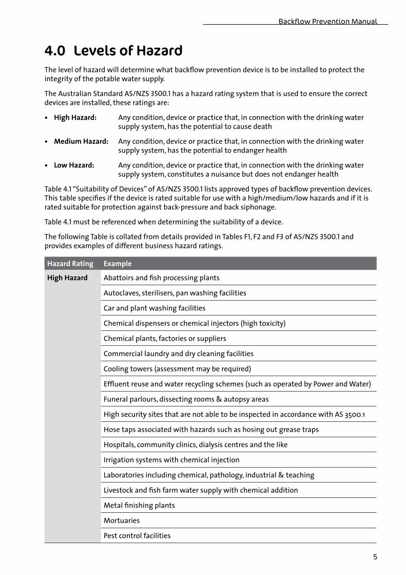
4.0 Levels of Hazard The level of hazard will determine what backflow prevention device is to be installed to protect the integrity of the potable water supply .
The Australian Standard AS/NZS 3500.1 has a hazard rating system that is used to ensure the correct devices are installed, these ratings are:
• HighHazard: Any condition, device or practice that, in connection with the drinking water supply system, has the potential to cause death
• MediumHazard: Any condition, device or practice that, in connection with the drinking water supply system, has the potential to endanger health
• LowHazard: Any condition, device or practice that, in connection with the drinking water supply system, constitutes a nuisance but does not endanger health
Table 4.1 “Suitability of Devices” of AS/NZS 3500.1 lists approved types of backflow prevention devices . This table specifies if the device is rated suitable for use with a high/medium/low hazards and if it is rated suitable for protection against back-pressure and back siphonage .
Table 4.1 must be referenced when determining the suitability of a device .
The following Table is collated from details provided in Tables F1, F2 and F3 of AS/NZS 3500.1 and provides examples of different business hazard ratings .
HazardRating Example
HighHazard Abattoirs and fish processing plants
Autoclaves, sterilisers, pan washing facilities
Car and plant washing facilities
Chemical dispensers or chemical injectors (high toxicity)
Chemical plants, factories or suppliers
Commercial laundry and dry cleaning facilities
Cooling towers (assessment may be required)
Effluent reuse and water recycling schemes (such as operated by Power and Water)
Funeral parlours, dissecting rooms & autopsy areas
High security sites that are not able to be inspected in accordance with AS 3500 .1
Hose taps associated with hazards such as hosing out grease traps
Hospitals, community clinics, dialysis centres and the like
Irrigation systems with chemical injection
Laboratories including chemical, pathology, industrial & teaching
Livestock and fish farm water supply with chemical addition
Metal finishing plants
Mortuaries
Pest control facilities
Power and Water Corporation
6
HazardRating Example
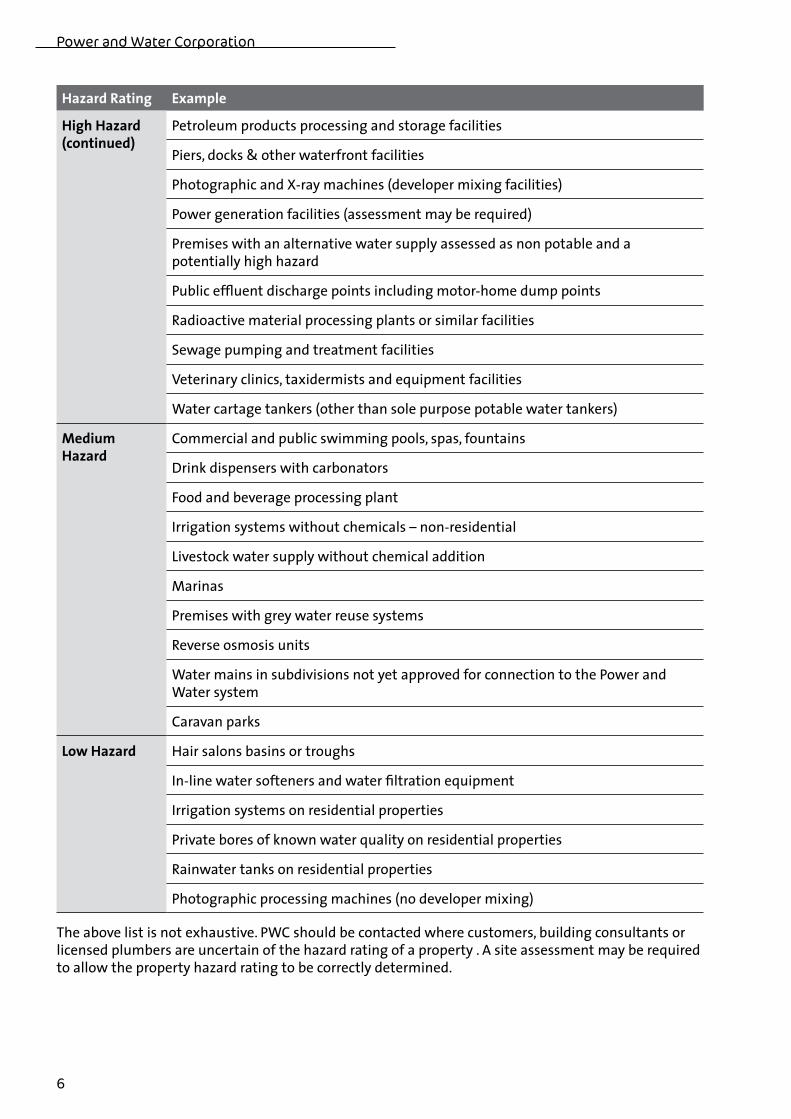
HighHazard(continued)
Petroleum products processing and storage facilities
Piers, docks & other waterfront facilities
Photographic and X-ray machines (developer mixing facilities)
Power generation facilities (assessment may be required)
Premises with an alternative water supply assessed as non potable and a potentially high hazard
Public effluent discharge points including motor-home dump points
Radioactive material processing plants or similar facilities
Sewage pumping and treatment facilities
Veterinary clinics, taxidermists and equipment facilities
Water cartage tankers (other than sole purpose potable water tankers)
MediumHazard
Commercial and public swimming pools, spas, fountains
Drink dispensers with carbonators
Food and beverage processing plant
Irrigation systems without chemicals – non-residential
Livestock water supply without chemical addition
Marinas
Premises with grey water reuse systems
Reverse osmosis units
Water mains in subdivisions not yet approved for connection to the Power and Water system
Caravan parks
LowHazard Hair salons basins or troughs
In-line water softeners and water filtration equipment
Irrigation systems on residential properties
Private bores of known water quality on residential properties
Rainwater tanks on residential properties
Photographic processing machines (no developer mixing)
The above list is not exhaustive . PWC should be contacted where customers, building consultants or licensed plumbers are uncertain of the hazard rating of a property . A site assessment may be required to allow the property hazard rating to be correctly determined .
Backflow Prevention Manual
7
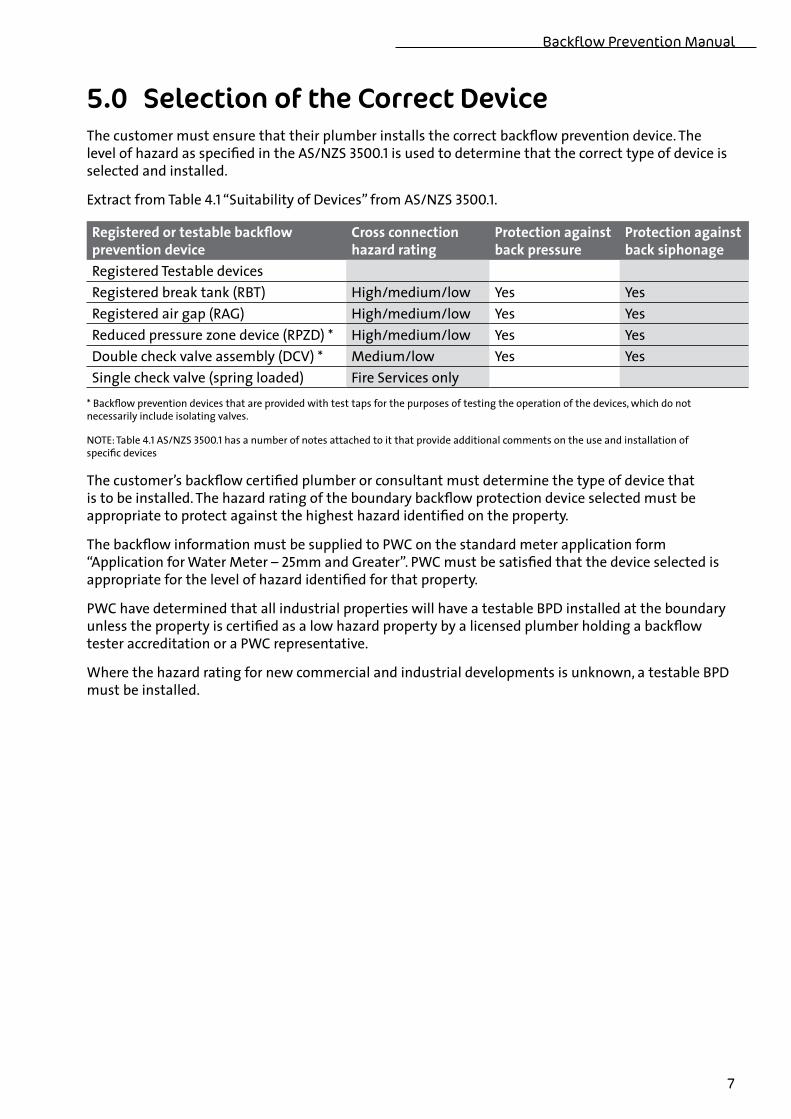
5.0 Selection of the Correct Device The customer must ensure that their plumber installs the correct backflow prevention device . The level of hazard as specified in the AS/NZS 3500.1 is used to determine that the correct type of device is selected and installed .
Extract from Table 4.1 “Suitability of Devices” from AS/NZS 3500.1.
Registeredortestablebackflowpreventiondevice
Crossconnectionhazardrating
Protectionagainstbackpressure
Protectionagainstbacksiphonage
Registered Testable devicesRegistered break tank (RBT) High/medium/low Yes YesRegistered air gap (RAG) High/medium/low Yes YesReduced pressure zone device (RPZD) * High/medium/low Yes YesDouble check valve assembly (DCV) * Medium/low Yes YesSingle check valve (spring loaded) Fire Services only
* Backflow prevention devices that are provided with test taps for the purposes of testing the operation of the devices, which do not necessarily include isolating valves .
NOTE: Table 4.1 AS/NZS 3500.1 has a number of notes attached to it that provide additional comments on the use and installation of specific devices
The customer’s backflow certified plumber or consultant must determine the type of device that is to be installed . The hazard rating of the boundary backflow protection device selected must be appropriate to protect against the highest hazard identified on the property .
The backflow information must be supplied to PWC on the standard meter application form “Application for Water Meter – 25mm and Greater” . PWC must be satisfied that the device selected is appropriate for the level of hazard identified for that property .
PWC have determined that all industrial properties will have a testable BPD installed at the boundary unless the property is certified as a low hazard property by a licensed plumber holding a backflow tester accreditation or a PWC representative .
Where the hazard rating for new commercial and industrial developments is unknown, a testable BPD must be installed .
Power and Water Corporation
8
6.0 Installation Requirements 6.1 Commercial and Industrial PropertiesPWC requires testable boundary backflow protection devices to be installed on properties that present a high or medium hazard to the potable water supply . In general, boundary backflow devices must, or will need to be installed regardless of any individual or zone protection installed by the customer . The only exception to this requirement will be as follows:
Where a property is supplied from a water meter that is DN80 or greater in size, and it is determined that only one hazard exists on that site, then a boundary backflow protection device may not be required providing the following conditions are complied with:
• PWCaresatisfiedthatthereisonlyonehazardontheexistingsite,orthattherewillonlybeonehazard on the planned development;
• Thehazardidentifiedpresentsarelativelylowrisktothesecurityofthepotablewatersupply;
• AzoneprotectiondevicethatcomplieswiththerelevantAustralianStandardsisspecifiedforthehazard and is accepted by PWC as being appropriate for the level of hazard;
• ThestandardPWCbackflowpreventionforms,“NoticeofInstallation”and“ValveTestCertificationReport” are completed and forwarded to PWC as specified in this Section;
• PWCwillregisterthezoneprotectiondeviceintheBackflowRegisterasbeingacceptableforthatsite; and,
• Thezoneprotectiondeviceistestedandcertifiedonanannualbasisandthe“ValveTestCertification Report” forwarded to PWC as specified in the Inspection, Testing and Maintenance Section of this manual .
Failure to comply with, or maintain the conditions specified above will negate the acceptance of a zone protection device, a boundary backflow protection device will then be required as specified in this Manual .
The installation of backflow devices must comply with the requirements of AS 3500.1, Section 4.6 “Installation of backflow prevention devices” .
The boundary backflow prevention device must be installed by a licensed plumber and the installation must comply with the requirements of AS/NZS 3500.1 . The plumber must complete the PWC standard document “Backflow Prevention – Notice of Installation” .
The completed document must be either handed to the PWC meter installer, or be forwarded to PWC within 10 working days .
Following installation, the backflow prevention device must be commissioned and tested by a person holding a backflow tester accreditation acceptable to the NT Plumbers and Drainers Licensing Board . The certifier must complete the PWC standard document “Backflow Prevention – Valve Test Certification Report”, the completed document must be either handed to the PWC meter installer or be forwarded to PWC within 10 working days . Completed documents may be scanned and e-mailed to:
backflowprevention@powerwater .com .au
The backflow prevention device must be installed on the downstream (outlet) side of the PWC meter to ensure site containment . The water meter and the backflow prevention device must be separated by the appropriate distance to ensure metering accuracy is maintained . The installation of the backflow prevention device must comply with the PWC Standard Drawings for water meter installations .
With the exception of fire services, in line strainers and isolation valves must be installed on testable devices . All in line devices shall be installed with connections that allow for simple removal and replacement of the device .
Backflow Prevention Manual
9
6.2 Residential PropertiesWhere a residential property has a PWC potable supply only, PWC will supply and install a 20mm or 25mm water meter that incorporates an integrated dual check valve assembly .
Residential properties with services greater than 25mm will be assessed for backflow requirements on an individual basis .
ResidentialPropertieswithRainWaterTanks:
Where a residential property has a PWC potable supply and a rainwater tank installed above ground without a pump system, PWC will supply and install a water meter that incorporates a dual check valve assembly . For services greater than 25mm a separate backflow prevention device will be required .
Where a rainwater tank is installed above or below ground and a pump is connected to the rainwater system, PWC will require the property owner to supply and install a non testable dual check valve with an atmospheric port . The valve must be installed on the outlet side (downstream) of the water meter, no off-take or connection is permitted between the water meter and the valve .
ResidentialPropertieswithanOn-siteBorePump:
Where a residential property has a PWC potable supply, and has an alternate water supply from an on-site bore-pump system, PWC will require a non testable dual check valve with an atmospheric port to be installed, provided the alternate water supply has been assessed as a low hazard .
The property owner will be responsible for the supply and installation of the valve . The valve will be installed as containment protection on the outlet side (downstream) of the water meter, no off-take or connection is permitted between the water meter and the valve .
Where a residential property has a device or system installed on-site that represents a hazard to the potable water supply (such as a chemical injection system) then an approved testable backflow prevention device must be fitted as boundary protection at the water meter installation .
For further installation requirements refer to the relevant PWC Fact Sheets for residential properties with alternate water supply systems .
ResidentialPropertieswithGreyWaterRe-useSystems:
Where a residential property has a temporary or manually operated grey water reuse system installed without treatment or storage facilities, PWC will not require an additional backflow prevention device to be installed . The property owner should advise PWC of their intent to use grey water to allow the Corporation to ensure that a water meter that incorporates a dual check valve assembly is installed .
Where a residential property has a grey water treatment system installed, the property owner and their licensed plumber must comply with the Department of Health and Families requirements . The Department of Health and Families specifies that the system must be registered with their Department and must be installed by a licensed plumber . PWC will require a licensed plumber with a backflow tester accreditation to assess the hazard rating of the property and to install the appropriate testable backflow prevention device as boundary protection at the water meter installation .
Property owners should obtain copies of, and comply with the requirements of the grey water reuse Fact Sheets supplied by the Department of Health and Families .
Power and Water Corporation
10
6.3 Fire ServicesFor fire service installations PWC has determined that the following will apply:
• Ifabreaktankisinstalledwithanapproved“registered”airgap,thisinstallationwillcomplywithbackflow requirements and will be registered in the backflow database .
• Providedtherearenodirectconnectionstothepipeworkbetweenthemeterassemblyandthebreak tank, a backflow prevention device will not be required at the meter installation .
• Thepipeworkbetweenthemeterandthebreaktankmustbevisuallyinspectedeachyearinconjunction with the check of the registered air gap to confirm that no tappings have been made upstream of the break tank .
• Whereaseparatefireserviceisinstalled,onlyautomaticfiresprinklersystemsandfixedfirehydrants can be connected to the fire service . As a minimum, a testable spring loaded single check valve must be installed as boundary protection at the fire service water meter installation .
Remote monitoring of fire sprinkler systems by the Fire Brigade is considered sufficient to mitigate the risk of cross connection . The use of lay-flat hose with fire hydrants is considered satisfactory to mitigate the risk of back siphonage occurring .
• Existingbuildingsareexemptfromthenewfireservicerequirementsuntiloneofthefollowingconditions applies:
- A building upgrade or redevelopment requires a Development Application to be submitted;
- The property is re-zoned at the property owner‘s request;
- The area of the property changes due to subdivision or combining with one or more other lots;
- The service connection is upgraded at the property owner’s request;
• Firehosereelsmust,ingeneral,beconnectedtothedomesticsupply.Thisistoensurethatwaterconsumption is metered when fire hose reels are used for a number of unauthorised tasks .
• Wherefirehosereelsareconnectedtothegeneralsupply,thewatermetershallbeDN40 or larger .
• Whereabreaktankhasbeeninstalled,firehosereelsmay,atthediscretionofthepropertyowner,be connected to the fire service .
6.4 Remote Indigenous Communities:Water supplies managed and operated by PWC on remote indigenous communities may require special consideration with regard to the installation, testing and maintenance of backflow prevention devices . Backflow requirements should be checked with the relevant officers of the Alice Springs and Darwin Remote Operations Groups .
Backflow Prevention Manual
11
7.0 Inspection, Testing and MaintenanceRegistered backflow protection devices must be tested as follows:
• Immediatelyafterinstallation;
• Annually(atintervalsnotexceeding12 months);
• Oncompletionofmaintenancework;
• Afterabackfloworsuspectedbackflowincident;
• AttherequestofPWC.
The property owner is responsible for ensuring that the backflow prevention device is tested annually, on completion of maintenance work, and after suspected backflow incident(s) by an approved certifier and the results forwarded to PWC .
The property owner is responsible for all costs associated with the testing, maintenance and replacement of backflow prevention devices when necessary .
If an additional test is undertaken at the request of PWC, then the test will be paid for by the Corporation provided the backflow prevention device passes the test, otherwise the testing of the device is to be paid for by the property owner .
Testing of backflow prevention devices shall be undertaken in accordance with requirements of AS 2845.3 and this manual . All test kits used by licensed plumbers for testing must be calibrated annually in accordance with AS 2845.3.
Test tags must be securely fastened to each device and must have sufficient space for five test results to be recorded . The tag shall show:
• Dateoftest;
• Nameofcompany;
• Nameandregisterednumberofcertifiedtester.
Tags must be of suitable material for a working life of at least five years without deterioration .
The licensed plumber who holds a backflow tester accreditation must, within 10 working days, complete the PWC standard document “Backflow Prevention – Valve Test Certification Report”, the completed document must be forwarded to the PWC .
PWC maintains a register of all approved testable boundary protection devices for general services and fire services . Where approved boundary protection devices are registered, a reminder letter will be sent to the property owner advising that the annual test is due . The letter will be sent 60 days prior to the scheduled test date . If PWC have not received an approved “Backflow Prevention – Valve Test Certification Report” by the expiry date, a further letter will be sent to the property owner advising that the device must be tested immediately . If PWC has not received the required document by the due date then the installation shall be deemed non-compliant .
Where a property is deemed non-compliant, PWC will take appropriate action to ensure the safety and security of the water supply . PWC may arrange for the device to be tested and maintenance work initiated as required, all costs associated with the test and maintenance of the backflow prevention device will be directed to the property owner . An administration fee may be charged to recover costs associated with coordinating the testing of the device .
PWC is empowered under the Water Supply and Sewerage Services Act to disconnect, from supply, any property that it considers is a hazard to the potable water supply .
Power and Water Corporation
12
8.0 Removal of Backflow Prevention Devices from the RegisterIf the use of the property with backflow protection changes permanently so that the hazard level is reduced and, in accordance with the Australian Standards there is no requirement for a testable backflow prevention device, the property owner may apply to PWC to have the device removed from the register .
The owner’s licensed plumber (whose licence must be endorsed as holding a backflow tester accreditation) will re-assess the hazard rating of the property and complete a “Backflow Prevention – Application for Removal of a Backflow Prevention Device from the Backflow Register” and submit it to the PWC .
PWC will re-assess the hazard rating of the property in light of the information supplied by the licensed plumber, and, if the hazard level has reduced permanently, then the device will be removed from the Backflow Register and annual maintenance and testing will no longer be required by PWC .
Backflow Prevention Manual
13
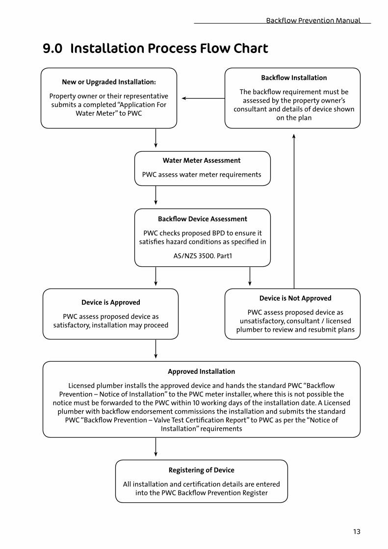
9.0 Installation Process Flow Chart
NeworUpgradedInstallation:
Property owner or their representative submits a completed “Application For
Water Meter” to PWC
BackflowInstallation
The backflow requirement must be assessed by the property owner’s
consultant and details of device shown on the plan
WaterMeterAssessment
PWC assess water meter requirements
BackflowDeviceAssessment
PWC checks proposed BPD to ensure it satisfies hazard conditions as specified in
AS/NZS 3500. Part1
DeviceisApproved
PWC assess proposed device as satisfactory, installation may proceed
DeviceisNotApproved
PWC assess proposed device as unsatisfactory, consultant / licensed
plumber to review and resubmit plans
ApprovedInstallation
Licensed plumber installs the approved device and hands the standard PWC “Backflow Prevention – Notice of Installation” to the PWC meter installer, where this is not possible the
notice must be forwarded to the PWC within 10 working days of the installation date . A Licensed plumber with backflow endorsement commissions the installation and submits the standard
PWC “Backflow Prevention – Valve Test Certification Report” to PWC as per the “Notice of Installation” requirements
RegisteringofDevice
All installation and certification details are entered into the PWC Backflow Prevention Register
Power and Water Corporation
14
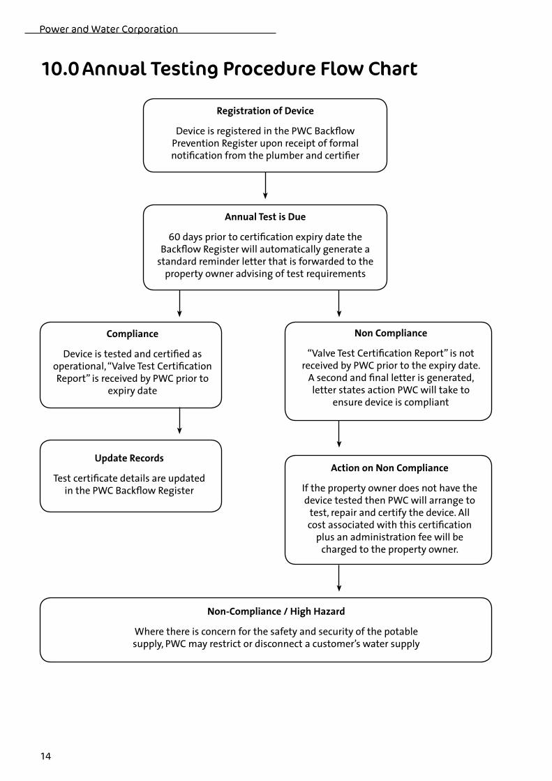
10.0 Annual Testing Procedure Flow Chart
RegistrationofDevice
Device is registered in the PWC Backflow Prevention Register upon receipt of formal notification from the plumber and certifier
AnnualTestisDue
60 days prior to certification expiry date the Backflow Register will automatically generate a
standard reminder letter that is forwarded to the property owner advising of test requirements
Compliance
Device is tested and certified as operational, “Valve Test Certification Report” is received by PWC prior to
expiry date
NonCompliance
“Valve Test Certification Report” is not received by PWC prior to the expiry date .
A second and final letter is generated, letter states action PWC will take to
ensure device is compliant
UpdateRecords
Test certificate details are updated in the PWC Backflow Register
ActiononNonCompliance
If the property owner does not have the device tested then PWC will arrange to
test, repair and certify the device . All cost associated with this certification
plus an administration fee will be charged to the property owner .
Non-Compliance/HighHazard
Where there is concern for the safety and security of the potable supply, PWC may restrict or disconnect a customer’s water supply
Backflow Prevention Manual
15
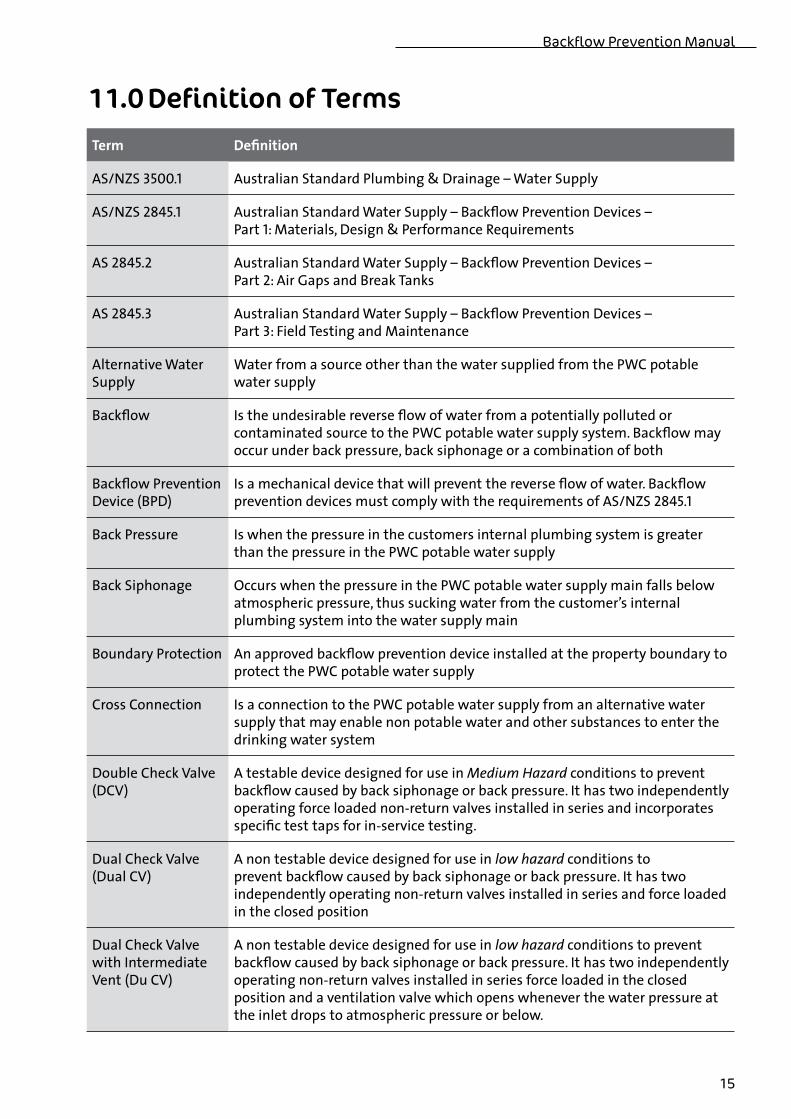
11.0 Definition of TermsTerm Definition
AS/NZS 3500.1 Australian Standard Plumbing & Drainage – Water Supply
AS/NZS 2845.1 Australian Standard Water Supply – Backflow Prevention Devices – Part 1: Materials, Design & Performance Requirements
AS 2845.2 Australian Standard Water Supply – Backflow Prevention Devices – Part 2: Air Gaps and Break Tanks
AS 2845.3 Australian Standard Water Supply – Backflow Prevention Devices – Part 3: Field Testing and Maintenance
Alternative Water Supply
Water from a source other than the water supplied from the PWC potable water supply
Backflow Is the undesirable reverse flow of water from a potentially polluted or contaminated source to the PWC potable water supply system . Backflow may occur under back pressure, back siphonage or a combination of both
Backflow Prevention Device (BPD)
Is a mechanical device that will prevent the reverse flow of water . Backflow prevention devices must comply with the requirements of AS/NZS 2845.1
Back Pressure Is when the pressure in the customers internal plumbing system is greater than the pressure in the PWC potable water supply
Back Siphonage Occurs when the pressure in the PWC potable water supply main falls below atmospheric pressure, thus sucking water from the customer’s internal plumbing system into the water supply main
Boundary Protection An approved backflow prevention device installed at the property boundary to protect the PWC potable water supply
Cross Connection Is a connection to the PWC potable water supply from an alternative water supply that may enable non potable water and other substances to enter the drinking water system
Double Check Valve (DCV)
A testable device designed for use in Medium Hazard conditions to prevent backflow caused by back siphonage or back pressure . It has two independently operating force loaded non-return valves installed in series and incorporates specific test taps for in-service testing .
Dual Check Valve (Dual CV)
A non testable device designed for use in low hazard conditions to prevent backflow caused by back siphonage or back pressure . It has two independently operating non-return valves installed in series and force loaded in the closed position
Dual Check Valve with Intermediate Vent (Du CV)
A non testable device designed for use in low hazard conditions to prevent backflow caused by back siphonage or back pressure . It has two independently operating non-return valves installed in series force loaded in the closed position and a ventilation valve which opens whenever the water pressure at the inlet drops to atmospheric pressure or below .
Power and Water Corporation
16
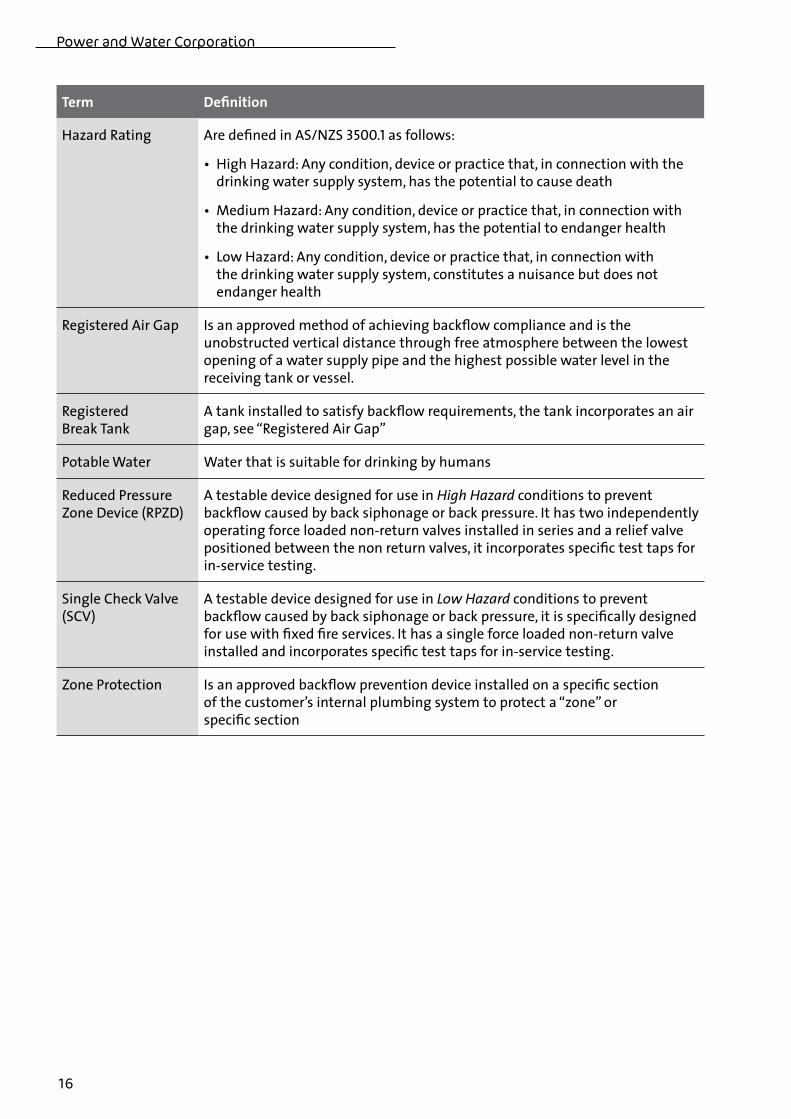
Term Definition
Hazard Rating Are defined in AS/NZS 3500.1 as follows:
•HighHazard:Anycondition,deviceorpracticethat,inconnectionwiththedrinking water supply system, has the potential to cause death
•MediumHazard:Anycondition,deviceorpracticethat,inconnectionwiththe drinking water supply system, has the potential to endanger health
•LowHazard:Anycondition,deviceorpracticethat,inconnectionwith the drinking water supply system, constitutes a nuisance but does not endanger health
Registered Air Gap Is an approved method of achieving backflow compliance and is the unobstructed vertical distance through free atmosphere between the lowest opening of a water supply pipe and the highest possible water level in the receiving tank or vessel .
Registered Break Tank
A tank installed to satisfy backflow requirements, the tank incorporates an air gap, see “Registered Air Gap”
Potable Water Water that is suitable for drinking by humans
Reduced Pressure Zone Device (RPZD)
A testable device designed for use in High Hazard conditions to prevent backflow caused by back siphonage or back pressure . It has two independently operating force loaded non-return valves installed in series and a relief valve positioned between the non return valves, it incorporates specific test taps for in-service testing .
Single Check Valve (SCV)
A testable device designed for use in Low Hazard conditions to prevent backflow caused by back siphonage or back pressure, it is specifically designed for use with fixed fire services . It has a single force loaded non-return valve installed and incorporates specific test taps for in-service testing .
Zone Protection Is an approved backflow prevention device installed on a specific section of the customer’s internal plumbing system to protect a “zone” or specific section
Backflow Prevention Manual
17
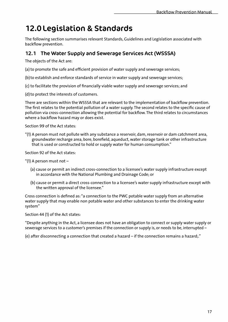
12.0 Legislation & Standards The following section summarises relevant Standards, Guidelines and Legislation associated with backflow prevention .
12.1 The Water Supply and Sewerage Services Act (WSSSA)The objects of the Act are:
(a) to promote the safe and efficient provision of water supply and sewerage services;
(b) to establish and enforce standards of service in water supply and sewerage services;
(c) to facilitate the provision of financially viable water supply and sewerage services; and
(d) to protect the interests of customers .
There are sections within the WSSSA that are relevant to the implementation of backflow prevention . The first relates to the potential pollution of a water supply . The second relates to the specific cause of pollution via cross-connection allowing the potential for backflow . The third relates to circumstances where a backflow hazard may or does exist .
Section 99 of the Act states:
“(1) A person must not pollute with any substance a reservoir, dam, reservoir or dam catchment area, groundwater recharge area, bore, borefield, aqueduct, water storage tank or other infrastructure that is used or constructed to hold or supply water for human consumption .”
Section 92 of the Act states:
“(1) A person must not –
(a) cause or permit an indirect cross-connection to a licensee’s water supply infrastructure except in accordance with the National Plumbing and Drainage Code; or
(b) cause or permit a direct cross-connection to a licensee’s water supply infrastructure except with the written approval of the licensee .”
Cross connection is defined as: “a connection to the PWC potable water supply from an alternative water supply that may enable non potable water and other substances to enter the drinking water system”
Section 44 (1) of the Act states:
“Despite anything in the Act, a licensee does not have an obligation to connect or supply water supply or sewerage services to a customer’s premises if the connection or supply is, or needs to be, interrupted –
(e) after disconnecting a connection that created a hazard – if the connection remains a hazard; .”
Power and Water Corporation
18
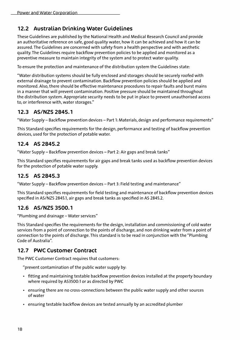
12.2 Australian Drinking Water GuidelinesThese Guidelines are published by the National Health and Medical Research Council and provide an authoritative reference on safe, good quality water, how it can be achieved and how it can be assured . The Guidelines are concerned with safety from a health perspective and with aesthetic quality . The Guidelines require backflow prevention policies to be applied and monitored as a preventive measure to maintain integrity of the system and to protect water quality .
To ensure the protection and maintenance of the distribution system the Guidelines state:
“Water distribution systems should be fully enclosed and storages should be securely roofed with external drainage to prevent contamination . Backflow prevention policies should be applied and monitored . Also, there should be effective maintenance procedures to repair faults and burst mains in a manner that will prevent contamination . Positive pressure should be maintained throughout the distribution system . Appropriate security needs to be put in place to prevent unauthorised access to, or interference with, water storages .”
12.3 AS/NZS 2845.1“Water Supply – Backflow prevention devices – Part 1: Materials, design and performance requirements”
This Standard specifies requirements for the design, performance and testing of backflow prevention devices, used for the protection of potable water .
12.4 AS 2845.2“Water Supply – Backflow prevention devices – Part 2: Air gaps and break tanks”
This Standard specifies requirements for air gaps and break tanks used as backflow prevention devices for the protection of potable water supply .
12.5 AS 2845.3“Water Supply – Backflow prevention devices – Part 3: Field testing and maintenance”
This Standard specifies requirements for field testing and maintenance of backflow prevention devices specified in AS/NZS 2845.1, air gaps and break tanks as specified in AS 2845.2.
12.6 AS/NZS 3500.1“Plumbing and drainage – Water services”
This Standard specifies the requirements for the design, installation and commissioning of cold water services from a point of connection to the points of discharge, and non drinking water from a point of connection to the points of discharge . This standard is to be read in conjunction with the “Plumbing Code of Australia” .
12.7 PWC Customer ContractThe PWC Customer Contract requires that customers:
“prevent contamination of the public water supply by:
• fittingandmaintainingtestablebackflowpreventiondevicesinstalledatthepropertyboundarywhere required by AS3500:1 or as directed by PWC
• ensuringtherearenocross-connectionsbetweenthepublicwatersupplyandothersources of water
• ensuringtestablebackflowdevicesaretestedannuallybyanaccreditedplumber
Backflow Prevention Manual
19
12.8 Northern Territory Building Act and RegulationsWorks within or associated with Buildings are covered by this act – refer to the following extract from the Building Regulations
“Part2BuildingStandards
Section4BuildingCode,&c.,adopted
(1) Subject to these Regulations, the Building Code, the National Plumbing and Drainage Code as modified in Schedule 5 and the Code of Practice for Small On-site Sewage and Sullage Treatment Systems and the Disposal or Reuse of Sewage Effluent, November 1996, published by Territory Health Services apply to any building that can be classified according to use under Part A3.2 of the Building Code and to any building work referred to in the Act or in the Building Code . “
12.9 PWC Standard DrawingsThese show the required layouts for installation of backflow prevention devices at the property boundary .
http://www .powerwater .com .au/powerwater/business/connectioncode/pdfs_docs/standard_drawings/watsew/water/index_water .html
12.10 Related Fire StandardsThe water supply requirements of the following Fire Standards have been reviewed . The selection of appropriate backflow prevention devices have been made on the understanding that fire service installations comply with these Australian Standards .
AS 2118.1 Automatic fire sprinkler systems: Part 1: General systems
AS 2118.4 Automatic fire sprinkler systems: Part 4: Residential
AS 2118.6 Automatic fire sprinkler systems: Part 6: Combined sprinkler and hydrant
AS 2419.1 Hydrant installations: Part 1: System design, installation and commissioning
AS 2441 Installation of fire hose reels
AS 2941 Fixed fire protection installations – Pumpset systems
Power and Water Corporation
20
13.0 FormsPWC has developed the following forms to ensure the correct information is provided to the Corporation to allow the backflow register to be accurately maintained, the forms are:
• NOTICEOFINSTALLATION
• VALVETESTCERTIFICATIONREPORT
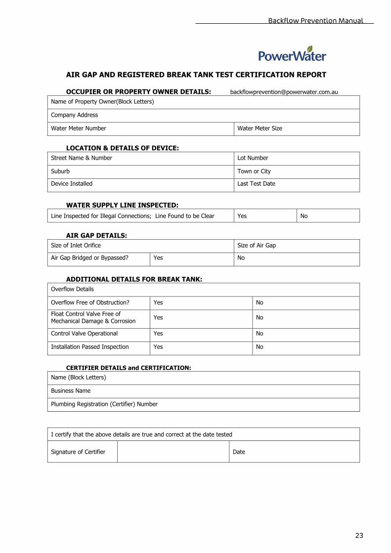
• AIRGAPANDREGISTEREDBREAKTANKTESTCERTIFICATIONREPORT
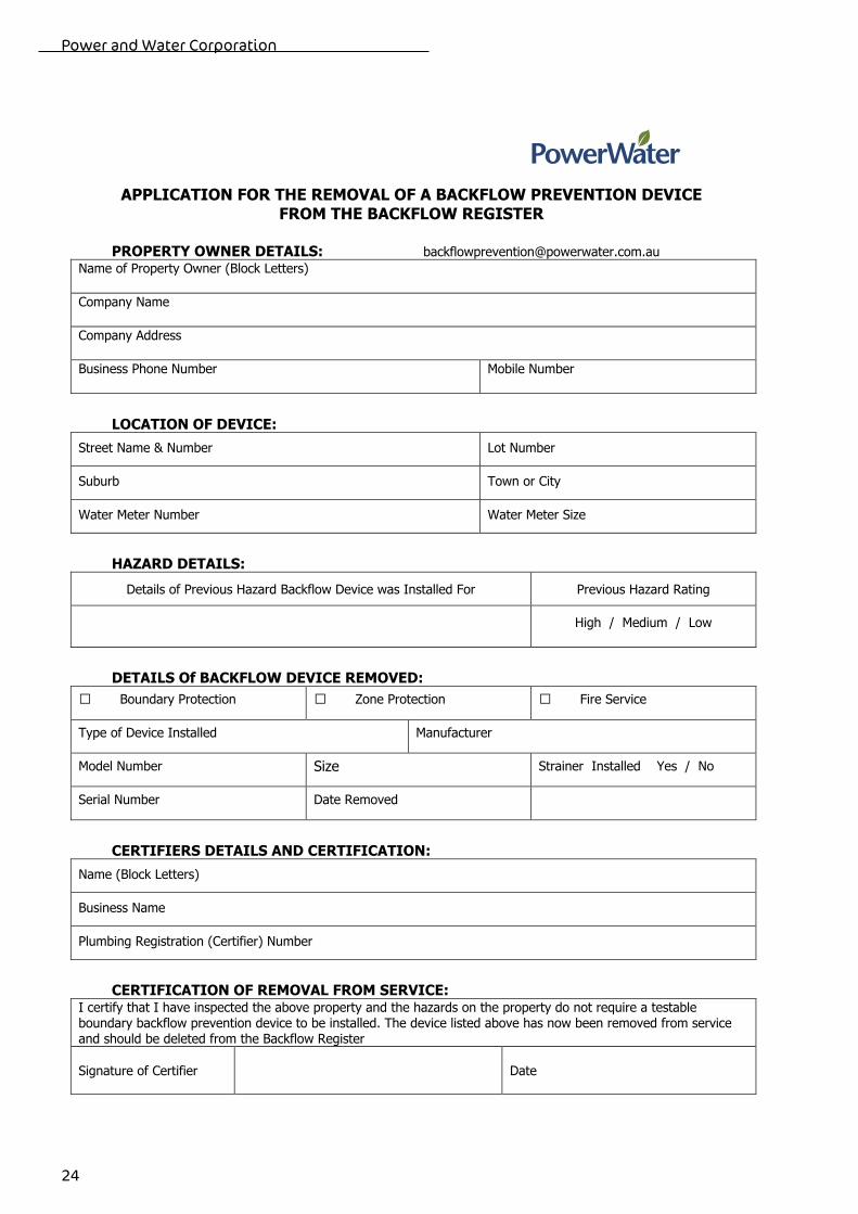
• APPLICATIONFORTHEREMOVALOFABACKFLOWPREVENTIONDEVICEFROMTHE BACKFLOWREGISTER
The forms will be printed in book copies and supplied to licensed plumbers upon request; the forms are also available of the PWC web site: www .powerwater .com .au
Section 6, “Installation Requirements” and Section 7 “Inspection, Testing and Maintenance” of this manual specify PWC requirements for submitting the completed forms .
Licensed plumbing contractors may use their own backflow installation and testing report forms provided they include the relevant information required by PWC .
Backflow Prevention Manual
21
Power and Water Water Services
Uncontrolled Hard Copy Backflow Prevention Manual Page 26 of 30 Valid print date only January 2010 Printed 01/03/10
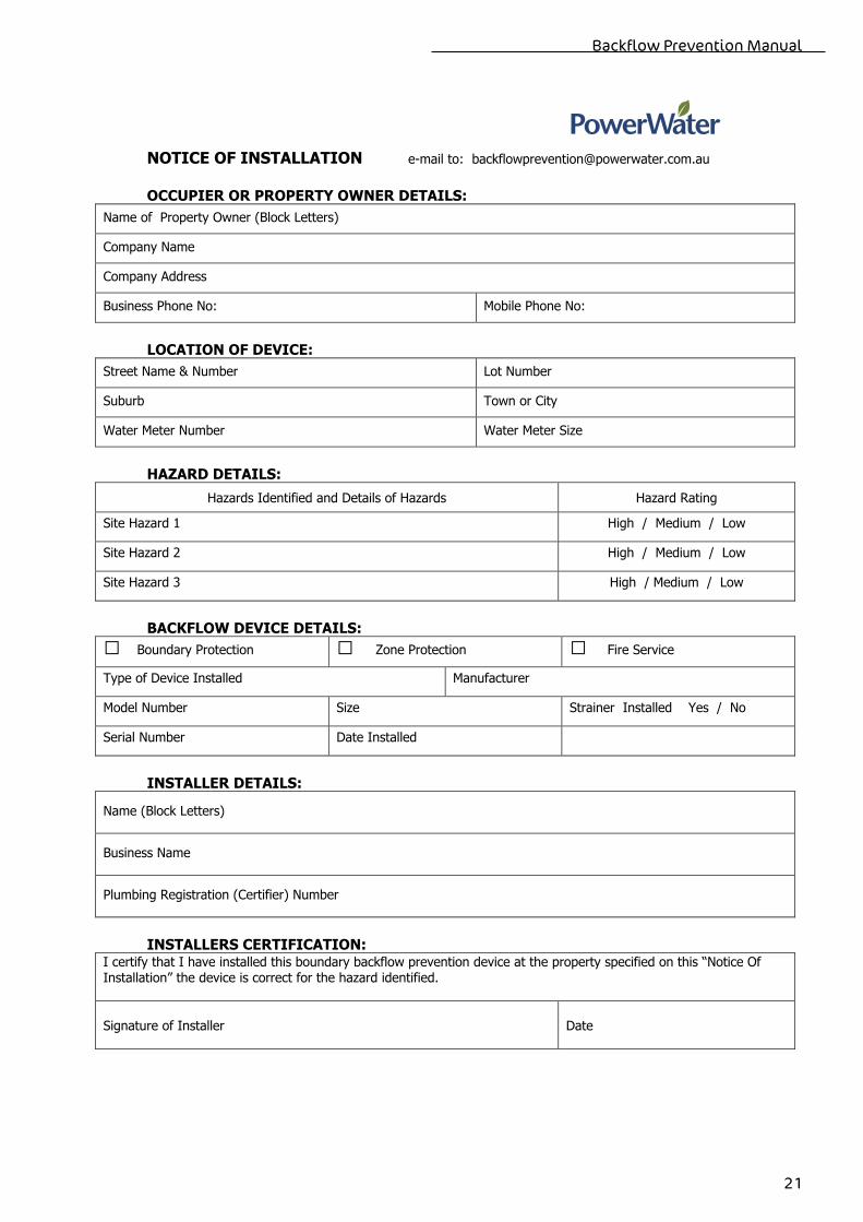
NOTICE OF INSTALLATION e-mail to: [email protected] OCCUPIER OR PROPERTY OWNER DETAILS:
Name of Property Owner (Block Letters)
Company Name
Company Address
Business Phone No: Mobile Phone No:
LOCATION OF DEVICE:
Street Name & Number Lot Number
Suburb Town or City
Water Meter Number Water Meter Size
HAZARD DETAILS:
Hazards Identified and Details of Hazards Hazard Rating
Site Hazard 1 High / Medium / Low
Site Hazard 2 High / Medium / Low
Site Hazard 3 High / Medium / Low
BACKFLOW DEVICE DETAILS:
� Boundary Protection � Zone Protection � Fire Service
Type of Device Installed Manufacturer
Model Number Size Strainer Installed Yes / No
Serial Number Date Installed
INSTALLER DETAILS:
Name (Block Letters)
Business Name
Plumbing Registration (Certifier) Number
INSTALLERS CERTIFICATION:
I certify that I have installed this boundary backflow prevention device at the property specified on this “Notice Of Installation” the device is correct for the hazard identified.
Signature of Installer
Date
Power and Water Corporation
22
Power and Water Water Services
Uncontrolled Hard Copy Backflow Prevention Manual Page 27 of 30 Valid print date only January 2010 Printed 01/03/10
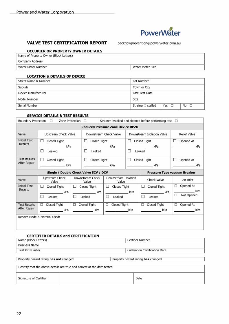
VALVE TEST CERTIFICATION REPORT [email protected]
OCCUPIER OR PROPERTY OWNER DETAILS
Name of Property Owner (Block Letters)
Company Address
Water Meter Number Water Meter Size
LOCATION & DETAILS OF DEVICE
Street Name & Number Lot Number
Suburb Town or City
Device Manufacturer Last Test Date
Model Number Size
Serial Number Strainer Installed Yes � No �
SERVICE DETAILS & TEST RESULTS
Boundary Protection � Zone Protection � Strainer installed and cleaned before performing test �
Reduced Pressure Zone Device RPZD
Valve Upstream Check Valve Downstream Check Valve Downstream Isolation Valve Relief Valve
Initial Test Results
� Closed Tight
__________ kPa
� Leaked
� Closed Tight
__________ kPa
� Leaked
� Closed Tight
__________ kPa
� Leaked
� Opened At
_________kPa
Test Results After Repair
� Closed Tight
__________ kPa
� Closed Tight
__________ kPa
� Closed Tight
__________ kPa
� Opened At
_________kPa
Single / Double Check Valve SCV / DCV Pressure Type vacuum Breaker
Valve Upstream Check
Valve Downstream Check
Valve Downstream Isolation
Valve Check Valve Air Inlet
Initial Test Results
� Closed Tight
_________ kPa
� Leaked
� Closed Tight
_________ kPa
� Leaked
� Closed Tight
_________ kPa
� Leaked
� Closed Tight
_________ kPa
� Leaked
� Opened At
________ kPa
� Not Opened
Test Results After Repair
� Closed Tight
_________ kPa
� Closed Tight
________ kPa
� Closed Tight
_________kPa
� Closed Tight
________ kPa
� Opened At
________ kPa
Repairs Made & Material Used:
CERTIFIER DETAILS and CERTIFICATION Name (Block Letters) Certifier Number
Business Name Test Kit Number Calibration Certification Date
Property hazard rating has not changed Property hazard rating has changed
I certify that the above details are true and correct at the date tested
Signature of Certifier
Date
Backflow Prevention Manual
23
Power and Water Water Services
Uncontrolled Hard Copy Backflow Prevention Manual Page 28 of 30 Valid print date only January 2010 Printed 01/03/10
AIR GAP AND REGISTERED BREAK TANK TEST CERTIFICATION REPORT OCCUPIER OR PROPERTY OWNER DETAILS: [email protected]
Name of Property Owner(Block Letters)
Company Address
Water Meter Number Water Meter Size
LOCATION & DETAILS OF DEVICE:
Street Name & Number Lot Number
Suburb Town or City
Device Installed Last Test Date
WATER SUPPLY LINE INSPECTED:
Line Inspected for Illegal Connections; Line Found to be Clear Yes No
AIR GAP DETAILS:
Size of Inlet Orifice Size of Air Gap
Air Gap Bridged or Bypassed? Yes No
ADDITIONAL DETAILS FOR BREAK TANK:
Overflow Details
Overflow Free of Obstruction? Yes No
Float Control Valve Free of Mechanical Damage & Corrosion
Yes No
Control Valve Operational Yes No
Installation Passed Inspection Yes No
CERTIFIER DETAILS and CERTIFICATION:
Name (Block Letters)
Business Name
Plumbing Registration (Certifier) Number
I certify that the above details are true and correct at the date tested
Signature of Certifier
Date
Power and Water Corporation
24
Power and Water Water Services
Uncontrolled Hard Copy Backflow Prevention Manual Page 29 of 30 Valid print date only January 2010 Printed 01/03/10
APPLICATION FOR THE REMOVAL OF A BACKFLOW PREVENTION DEVICE FROM THE BACKFLOW REGISTER
PROPERTY OWNER DETAILS: [email protected]
Name of Property Owner (Block Letters)
Company Name
Company Address
Business Phone Number Mobile Number
LOCATION OF DEVICE:
Street Name & Number Lot Number
Suburb Town or City
Water Meter Number Water Meter Size
HAZARD DETAILS:
Details of Previous Hazard Backflow Device was Installed For Previous Hazard Rating
High / Medium / Low
DETAILS Of BACKFLOW DEVICE REMOVED:
� Boundary Protection � Zone Protection � Fire Service
Type of Device Installed Manufacturer
Model Number Size Strainer Installed Yes / No
Serial Number Date Removed
CERTIFIERS DETAILS AND CERTIFICATION:
Name (Block Letters)
Business Name
Plumbing Registration (Certifier) Number
CERTIFICATION OF REMOVAL FROM SERVICE:
I certify that I have inspected the above property and the hazards on the property do not require a testable boundary backflow prevention device to be installed. The device listed above has now been removed from service and should be deleted from the Backflow Register Signature of Certifier
Date