Embed Size (px)
Citation preview
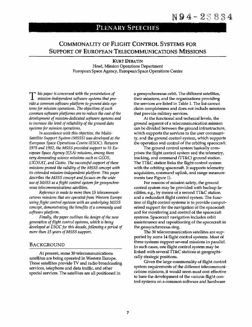
Head, Mission Operations Department European Space Agency, European Space Operations Centre
his paper is concerned with the presentation of T mission-independent software systems that pro- vide a common software platform to ground data sys- tems for mission operations. The objectives of such common software platforms are to reduce the cost of the development of mission-dedicated software systems and to increase the level of reliability of the ground data systems for mission operations.
In accordance with this objective, the Multi- Satellite Support System (MSSS) was developed at the European Space Operations Centre (ESOC). Between 1975 and 1992, the MSSS provided support to 16 Eu- ropean Space Agency (ESA) missions, among them very demanding science missions such as GEOS, EXOSAT, and Giotto. The successful support of these missions proved the validity of the MSSS concept with its extended mission-independent platform. This paper describes the MSSS concept and focuses on the wide use of MSSS as a flight control system for geosynchro- nous telecommunications satellites.
Reference is made to more than 15 telecommuni- cations missions that are operated from Western Europe using flight control systems with an underlying MSSS concept, demonstrating the benefits of a commonly used software platform.
generation of flight control systems, which is being developed at ESOC for this decade, following a period of more than 15 years of MSSS support.
Finally, the paper outlines the design of the new
BACKGROUND At present, some 30 telecommunications
satellites are being operated in Western Europe. These satellites provide TV and radio broadcasting services, telephone and data traffic, and other special services. The satellites are all positioned in
a geosynchronous orbit. The different satellites, their missions, and the organisa tions providing the services are listed in Table 1. Tne list cannot claim completeness and does not include missions that provide military services.
ground segment of a telecommunication mission can be divided between the ground infrastructure, which supports the services to the user communi- ty, and the ground control system, which supports the operation and control of the orbiting spacecraft.
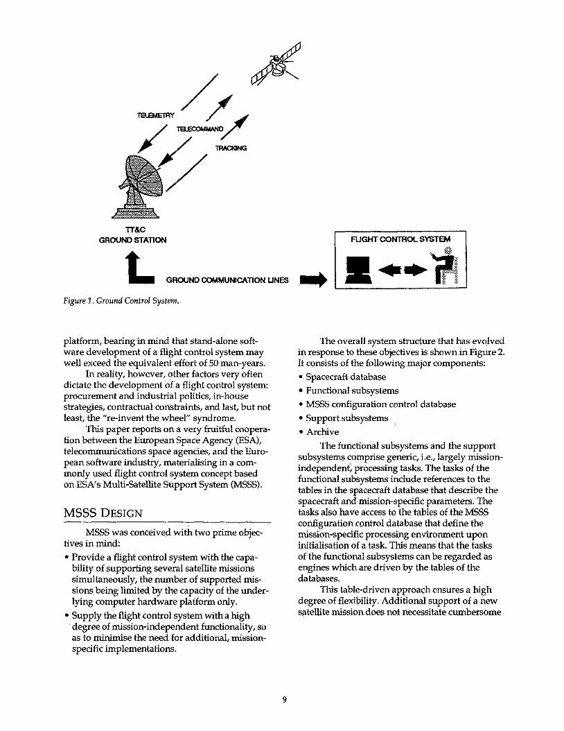
The ground control system basically com- prises the flight control system and the telemetry, tracking, and command (TT.&C) ground station. The TT&C station links the flight control system with the orbiting spacecraft. It supports telemetry acquisition, command uplink, and range measure- ments (see Figure 1).
For reasons of mission safety, the ground control system may be provided with backup fa- cilities, e.%., by means of a second TT&C station and a redundant flight control system. The func- tion of flight controI systems is to provide comput- erised support for the navigation of the spacecraft and for monitoring and control of the spacecraft systems. Spacecraft navigation includes orbit maintenance and repositioning of the spacecraft in the geosynchronous ring.
The 30 telecommunication satellites are sup- ported by some 14 flight control systems. Most of these systems support several missions in parallel. In such cases, one flight control system may be linked with several TT&C stations at geographi- cally strategic positions.
Given the large commonality of flight control system requirements of the different telecommuni- cations missions, it would seem most cost effective to base the development of the various flight con- trol systems on a common software and hardware
At the functional and technical levels, the
7
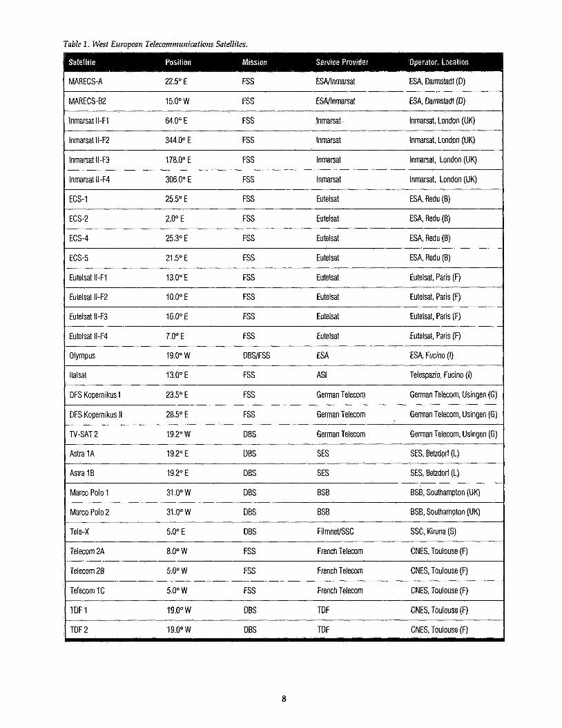
Table 1 , Wesf European Telecommunications Satellites.
I MARECS-A 22.5" E FSS ESAJlnmarsat ESA, Darmstadt (D)
MARECS-B2 15.0" W FSS ESNlnmarsat ESA, Darmstadt (D)
lnmarsat Il-Fl 64.0" E FSS lnmarsat Inmarsat, London (UK)
lnmarsat ll-F2 344.0" E FSS lnmarsat Inmarsat, London (UK)
lnmarsat ll-F3 178.0" E FSS Inmarsat Inmarsat, London (UK)
lnmarsat I N 4 306.0" E FSS lnmarsat Inmarsat, London (UK)
ECS-1 25.5" E FSS Eutelsat ESA, Redu (B)
ECS-2 2.0" E FSS Eutelsat ESA, Redu (B)
I ECS-4 25.3" E FSS Eu telsat ESA, Redu (B)
ECS-5 21.5" E FSS Eutelsat ESA, Redu (B)
Eutelsat Il-F1 13.0" E FSS Eutelsat Eutelsat, Paris (F)
Eutelsat ll-F2 10.0" E FSS Eutelsat Eutelsat, Paris (F)
I Eutelsat ll-F3 16.0" E FSS Eutelsat Eutelsat, Paris (F)
Eutelsat lI-F4 7.0" E FSS Eutelsat Eutelsat, Paris (F)
Olympus 19.0" w DBSIFSS ESA ESA, Fucino (I)
ltalsat 13.0" E FSS AS1 Telespazio, Fucino (I)
DFS Kopernikus I 23.5" E FSS German Telecom German Telecom, Usingen (G)
DFS Kopernikus II 28.5" E FSS German Telecom German Telecom, Usingen (G)
TV-SAT 2 19.2" W DBS German Telecom German Telecom, Usingen (G)
Astra 1A 19.2" E DBS SES SES, Betzdorf (L)
Astra 1 B 19.2" E DBS SES SES, Betzdorf (L)
Marco Polo 1 31 .O" W DBS BSB BSB, Southampton (UK)
Marco Polo 2 31 .Oo W DBS BSB BSB, Southampton (UK)
Tele-X 5.0" E DBS FilmneVSSC SSC, Kiruna (S)
Telecom 2A 8.0" W FSS French Telecom CNES, Toulouse (F) ~~~~~ ~
Telecom 2B 5.0" W FSS French Telecom CNES, Toulouse (F)
Telecom 1C 5.0" W FSS French Telecom CNES, Toulouse (F)
TDF 1 19.0" w DBS TDF CNES, Toulouse (F)
TDF 2 19.0" w DBS TDF CNES, Toulouse (F)
8
I NGHTCONlROLSYSTEM Tr&c
GROUND STATloN
t GROUND COMMUNlCATlON UNES
Figure 1. Ground Control System.
platform, bearing in mind that stand-alone soft- ware development of a flight control system may well exceed the equivalent effort of 50 man-years.
In reality, however, other factors very often dictate the development of a flight control system: procurement and industrial politics, in-house strategies, contractual constraints, and last, but not least, the “re-invent the wheel” syndrome.
This paper reports on a very fruitful coopera- tion between the European Space Agency (ESA), telecommunications space agencies, and the Euro- pean software industry, materialising in a com- monly used flight control system concept based on ESAs Multi-Satellite Support System (MSSS).
MSSS DESIGN MSSS was conceived with two prime objec-
tives in mind: 0 Provide a flight control system with the capa-
bility of supporting several satellite missions simultaneously, the number of supported mis- sions being limited by the capacity of the under- lying computer hardware platform only.
* Supply the flight control system with a high degree of mission-independent functionality, so as to minimise the need for additional, mission- specific implementations.
The overall system structure that has evolved in response to these objectives is shown in Figure 2. It consists of the following major components: 0 Spacecraft database
Functional subsystems * MSSS configuration control database 0 Support subsystems 0 Archive
subsystems comprise generic, i.e., largely mission- independent, processing tasks. The tasks of the functional subsystems include references to the tables in the spacecraft database that describe the spacecraft and mission-specific parameters. The tasks also have access to the tables of the MSSS configuration control database that define the mission-specific processing environment upon initialisation of a task. This means that the tasks of the functional subsystems can be regarded as engines which are driven by the tables of the databases.
degree of flexibility. Additional support of a new satellite mission does not necessitate cumbersome
The functional subsystems and the support
This table-driven approach ensures a high
9
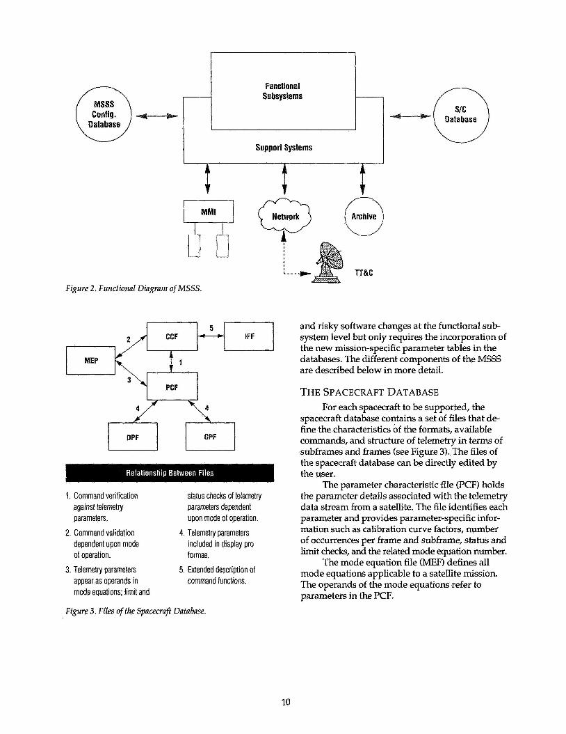
Figure 2.
Database
Support Systems
Functional Diagram of MSSS .
5 CCF - IFF
MEP 1
PCF
1. Command verification status checks of telemetry against telemetry parameters dependent parameters. upon mode of operation.
4. Telemetry parameters dependent upon mode of operation. formae.
3. Telemetry parameters appear as operands in mode equations; limit and
2. Command validation included in display pro
5. Extended description of command functions.
and risky software changes at the functional sub- system level but only requires the incorporation of the new mission-specific parameter tables in the databases. The different components of the MSSS are described below in more detail.
THE SPACECRAFT DATABASE For each spacecraft to be supported, the
spacecraft database contains a set of files that de- fine the characteristics of the formats, available commands, and structure of telemetry in terms of subframes and frames (see Figure 3). The files of the spacecraft database can be directly edited by the user.
The parameter characteristic file (PCF) holds the parameter details associated with the telemetry data stream from a satellite. The file identifies each parameter and provides parameter-specific infor- mation such as calibration curve factors, number of occurrences per frame and subframe, status and limit checks, and the related mode equation number.
The mode equation file (MEF) defines all mode equations applicable to a satellite mission. The operands of the mode equations refer to parameters in the PCF.
Figure 3. Files ofthe Spacecraff Database.
10
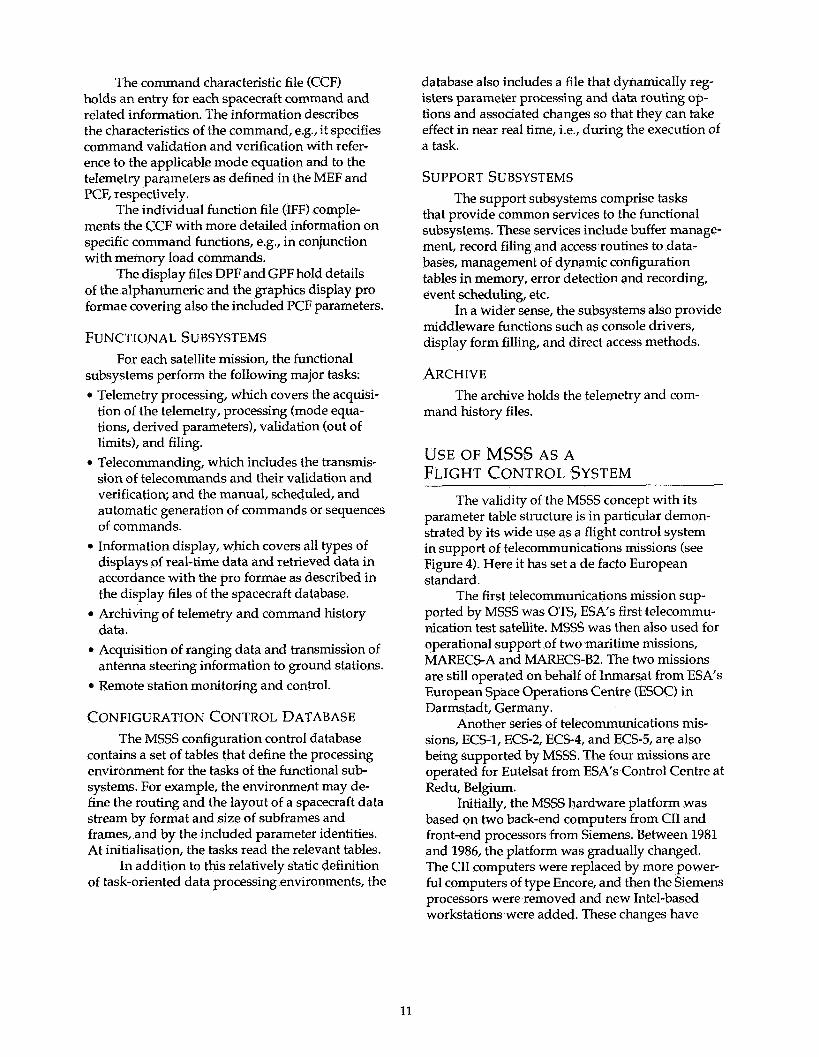
The command characteristic file (CCF) holds an entry for each spacecraft command and related information. The information describes the characteristics of the command, eg., it specifies command validation and verification with refer- ence to the applicable mode equation and to the telemetry parameters as defined in the MEF and PCF, respectively.
ments the CCF with more detailed information on specific command functions, e.g., in conjunction with memory load commands.
The display files DPF and GPF hold details of the alphanumeric and the graphics display pro formae covering also the included PCF parameters.
The individual function file (IFF) comple-
FUNCTIONAL SUBSYSTEMS For each satellite mission, the functional
subsystems perform the following major tasks: 0 Telemetry processing, which covers the acquisi-
tion of the telemetry, processing (mode equa- tions, derived parameters), validation (out of limits), and filing.
0 Telecommanding, which includes the transmis- sion of telecommands and their validation and verification; and the manual, scheduled, and automatic generation of commands or sequences of commands.
displays of real-time data and retrieved data in accordance with the pro formae as described in the display files of the spacecraft database.
0 Archiving of telemetry and command history data.
0 Acquisition of ranging data and transmission of antenna steering information to ground stations.
0 Remote station monitoring and control.
0 Information display, which covers all types of
CONFIGURATION CONTROL DATABASE The MSSS configuration control database
contains a set of tables that define the processing environment for the tasks of the functional sub- systems. For example, the environment may de- fine the routing and the layout of a spacecraft data stream by format and size of subframes and frames, and by the included parameter identities. At initialisation, the tasks read the relevant tables.
In addition to this relatively static definition of task-oriented data processing environments, the
database also includes a file that dynamically reg- isters parameter processing and data routing op- tions and associated changes so that they can take effect in near real time, i.e., during the execution of a task.
SUPPORT SUBSYSTEMS The support subsystems comprise tasks
that provide common services to the functional subsystems. These services include buffer manage- ment, record filing and access routines to data- bases, management of dynamic configuration tables in memory, error detection and recording, event scheduling, etc.
middleware functions such as console drivers, display form filling, and direct access methods.
In a wider sense, the subsystems also provide
ARCHIVE The archive holds the telemetry and com-
mand history files.
USE OF MSSS AS A FLIGHT CONTROL SYSTEM
The validity of the MSSS concept with its parameter table structure is in particular demon- strated by its wide use as a flight control system in support of telecommunications missions (see Figure 4). Here it has set a de facto European standard.
ported by MSSS was OTS, ESA's first telecommu- nication test satellite. MSSS was then also used for operational support of two maritime missions, MARECS-A and MARECS-B2. The two missions are still operated on behalf of Inmarsat from ESA's European Space Operations Centre (ESOC) in Darmstadt, Germany.
Another series of telecommunications mis- sions, ECS-1, ECS-2, ECS-4, and ECS-5, are also being supported by MSSS. The four missions are operated for Eutelsat from ESA's Control Centre at Redu, Belgium.
Initially, the MSSS hardware platform was based on two back-end computers from CII and front-end processors from Siemens. Between 1981 and 1986, the platform was gradually changed. The CII computers were replaced by more power- ful computers of type Encore, and then the Siemens processors were removed and new Intel-based workstations were added. These changes have
The first telecommunications mission sup-
11
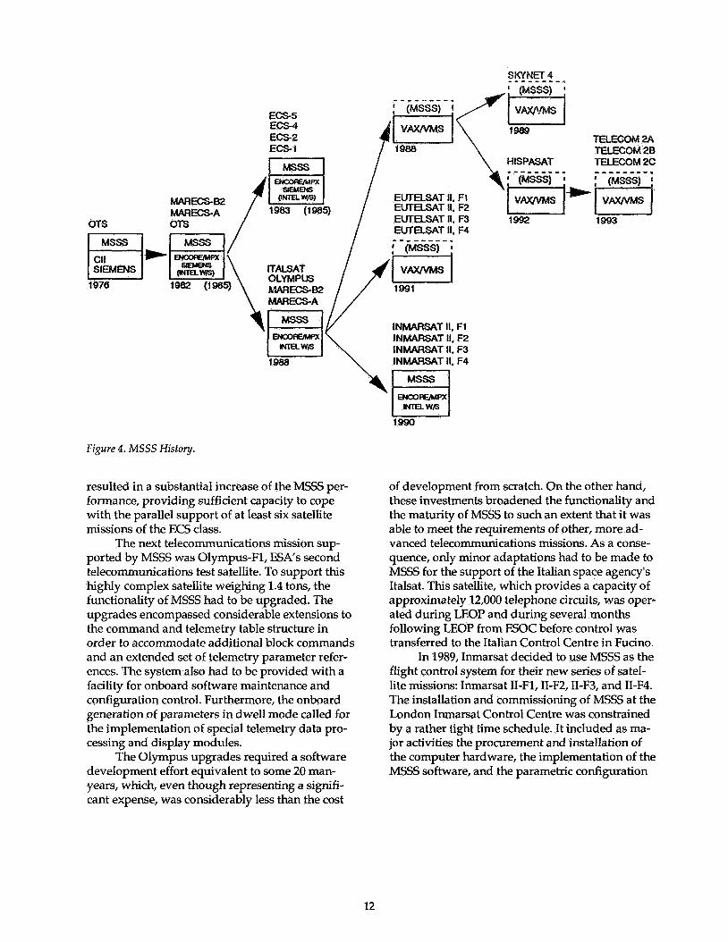
Ecs5 ECS-4 ECS-2 ECS-I
INMARSAT II. F1 INMARSAT II. F2 INMARSAT II. F3 INMARSAT II, F4
Figure 4. M S S S History.
resulted in a substantial increase of the MSSS per- formance, providing sufficient capacity to cope with the parallel support of at least six satellite missions of the ECS class.
The next telecommunications mission sup- ported by MSSS was Olympus-F1, ESA's second telecommunications test satellite. To support this highly complex satellite weighing 1.4 tons, the functionality of MSSS had to be upgraded. The upgrades encompassed considerable extensions to the command and telemetry table structure in order to accomoda te additional block commands and an extended set of telemetry parameter refer- ences. The system also had to be provided with a facility for onboard software maintenance and configuration control. Furthermore, the onboard generation of parameters in dwell mode called for the implementation of special telemetry data pro- cessing and dispIay modules.
The Olympus upgrades required a software development effort equivalent to some 20 man- years, which, even though representing a signifi- cant expense, was considerably less than the cost
of development from scratch. On the other hand, these investments broadened the functionality and the maturity of MSSS to such an extent that it was able to meet the requirements of other, more ad- vanced telecommunications missions. As a conse- quence, only minor adaptations had to be made to MSSS for the support of the Italian space agency's Italsat. This satellite, which provides a capacity of approximately 12,000 telephone circuits, was oper- ated during LEOP and during several months following LEOP from ESOC before control was transferred to the Italian Control Centre in Fucino.
In 1989, Inmarsat decided to use MSSS as the flight control sys tem for their new series of sa tel- lite missions: Inmarsat 11-Fl, II-F2,II-F3, and 11-F4. The installation and commissioning of MSSS at the London Inmarsat Control Centre was constrained by a rather tight time schedule. It included as ma- jor activities the procurement and installation of the computer hardware, the implementation of the MSSS software, and the parametric configuration
12
of the table structure in accordance with the spe- cific mission requirements. In addition, a number of modifications and enhancements to the system had to be implemented. They were mainly con- cerned with specific spacecraft requirements, e.g., onboard, time-tagged command control and com- mand confirmation; support of telecommand blocks; and dwell telemetry parameter displays. Also, station monitoring and control facilities were implemented with the same functionality as was provided for spacecraft monitoring and control. After one year, all tasks, including the enhance- ments, were completed and MSSS was ready for operation. The system is currently supporting the four Inmarsat missions and four TT&C stations.
European software companies have also adopted the MSSS concept for the fu;.ther develop- ment of flight control systems. In this way, their significant involvement in the development of MSSS at ESOC has come to fruition.
Science Systems Ltd., which received an MSSS software licence from ESA, transformed MSSS to a new platform on VAX/VMS computers from DEC. The new system, known as the Kernel TT&C System, was used as the basis of a flight control system which Science Systems Ltd. devel- oped for the British Ministry of Defence for the support of Skynet 4 and NATO IV. It was imple- mented as a distributed system on VAX machines and was provided with extensive redundancy and flexible reconfiguration capabilities at the basic system level to ensure the required high degree of system availability. The workstations were pro- vided with advanced display facilities based on X-Windows and GKS graphics software. This sys- tem in support of Skynet has been in operation since 1990 and provides services to the military.
Another implementation of the Kernel sys- tem was specifically tailored to the needs of the Eurostar platform. This involved, in particular, considerable enhancements to the telecommand subsystem. This new version provides the basis of the flight control system that supports the Hispa- sat mission from the Arganda Control Centre near Madrid, Spain. It will also constitute the core of the flight control system which will be used for the support of the French Telecom 2A, 2B, and 2C missions.
In parallel to this, the British firm Logica, based on an MSSS licence from ESA and in re- sponse to an order from Eutelsat, has also per-
formed an MSSS-based implementation on a hard- ware platform from DEC consisting of a VAX range of computers and VAX workstations. The
SSS table structure was implemented on a rela- tional database from Ingres. The major changes in the implementation by Logica are concerned with the provision of sophisticated display facilities on the workstations and with the processing and display of the spacecraft data stream at the level of frames rather than subframes. An only slightly modified version of this implementation will be used as a flight control system for the support of Turksat.
In conclusion, up to 20 telecommunications missions have been supported by flight control systems with an MSSS-based architecture. It has to be recognised, however, that the diverse systems show considerable variations. Incremental system changes of a more or less substantial nature have been introduced since 1976, when MSSS was used for the first time. This is not surprising, when one considers the different technical, contractual, and political frame conditions under which these sys- tems have been implemented during a period of more than 15 years.
Different operations concepts have evolved, which have in particular brought about consider- able extensions of the display facilities on the workstations. Major system changes arose from different spacecraft designs and mission require- ments in combination with the changeover of the computer platform from Encore/MPS to VAX/ VMS. Notwithstanding these differences, the vari- ous systems can be traced back to a common archi- tecture, and this has reduced cost and technical risks far below the level that normally has to be assumed for new and independent developments.
Associated with MSSS, the Portable ESOC Package for Synchronous Orbit Control (PEPSOC) was developed at ESOC. It is used for orbital con- trol of geosynchronous satellite missions, i.e., it determines the orbital position of the spacecraft by means of range measurements and specifies the orbit manoeuvres (velocity increment vectors) for repositioning the spacecraft.
workstation or on a PC and can be easily inter- faced with any flight control system. PEPSOC is
PEPSOC is a software package that runs on a
13
recognised as a standard tool by the European space community, not only in connection with MSSSbased systems, as proven by more than 17 PEPSOC licences that have been granted to indus- try and space agencies.
The future evolution of flight control systems will be determined by the increasing complexity of spacecraft systems and by the introduction of in- novative informatics technologies.
ESOC has given due consideration to this foreseeable evolution and has started with the development of the architecture for a new genera- tion of flight control systems. Following the MSSS success story, the new generation, named Space- craft Operations System (SCOS), is intended to cover the agency's requirements over the next decade for the support of different classes of mis- sions, including telecommunications missions and highly complex science missions.
In essence, the new architecture features the following elements: 0 Packetised telemetry and telecommanding ac-
0 Object-oriented approach. 0 UNIX-based platform.
packets in combination with the object-oriented processing approach will provide the user with more efficient and comprehensive access to the functionality of the individual subsystems and units of the orbiting spacecraft. The database will
cording to the defined CCSDS standards.
The handling of telemetry and command
hold operational procedures and associated data that can be addressed as concise entities. In many respects, the changeover from MSSS to SCOS can be compared with the parallel technological move from a relational database to an object-oriented database approach.
mission-independent system platform. This will be accomplished by taking advantage of the inher- itance feature of object-oriented modules and by a possible later introduction of packet utilisation standards, which will define the data files in the TM/TC packets.
The choice of UNIX as the operating system is obvious because of its worldwide recognition as an international standard. Although UNIX is not conceived as a real-time operating system, there now exist UNIX versions that offer real-time capabilities. The UNIX platform will be structured around a network of UNIX-supported worksta- tions. The integration of the workstations into a LAN-based structure with distributed client and server functions provides an environment that can be easily configured to the needs of different classes of missions and in the short term to differ- ent mission scenarios.
The workstations provide the capacity for the support of the required processing and data- base functions, and advanced human-machine interfaces based on the UNIX operating system. UNIX will ensure portability of SCOS between different hardware platforms and thus removes a traditional problem associated with MSSS.
Similar to MSSS, SCOS will provide a large,
14