Embed Size (px)
Citation preview

Backhauling 3G and 2G Traffic with Point-to-Multipoint Radio Systems
January 2003
© 2003 Hughes Network Systems, Inc. 1 HNS-26618
A White Paper for Telecommunications Service Providers Using the HUGHES AIReach® 9000 System
1.0 Backhauling 3G and 2G Traffic with Point-to-Multipoint Radio Systems
This AIReach Broadband White Paper introduces the application of new point-to-multipoint (PMP) radio systems for backhauling traffic in 2G and, particularly, 3G mobile networks. It discusses how PMP systems by nature offer capabilities that cannot be matched by the point-to-point (PTP) radio or leased line approaches currently in use. It also discusses how, by virtue of its inherent ability to share radios, PMP can offer a much more cost-effective backhaul solution than PTP approaches. This paper’s intended audience is the technical and business staffs of telecommunications service providers who are or are considering taking advantage of the AIReach 9000 system for broadband wireless access networks
1.1 Introduction
3G, shorthand for the third generation of mobile wireless equipment, is the term applied to the new systems that unify voice and data in mobile networks. These systems will usher in new features including many that depend upon high-speed data transport. Whether they are based on WCDMA, CDMA2000 series, or other approaches, 3G systems are revolutionizing mobile communications. According to the UMTS Forum, revenues from 3G systems will increase rapidly over the next 10 years throughout the world. For example, annual revenues in Europe are projected to reach $10B by 2004 and $79B by 2010. Data is the fuel driving 3G’s growth. 3G technology provides a much higher capacity for moving high bandwidth traffic than its predecessors could. Bandwidth is assigned dynamically, so that a large pool of bandwidth is available to a user. Wasted bandwidth is virtually eliminated. A fundamental feature of 3G is that the transport between the radio nodes (RN) and the radio node controllers (RNC) is defined as packetized transport. Packetized transport offers many efficiency and cost benefits for the transport network, especially when the transport network is based on PMP wireless technology (also known as local multipoint distribution system (LMDS)).
1.2 Unique Fit of Point-to-Multipoint for 3G
Next-generation PMP systems such as AIReach 9000 are an ideal match backhauling 3G traffic. This fit is primarily derived from the packetized nature of both PMP transport and 3G interfaces. Transport in an advanced PMP system is “payload-aware,” so the system operates synergistically with the 3G network. The synergies include:
© 2003 Hughes Network Systems, Inc. 2 HNS-26618
• 3G backhaul interfaces with packetized payloads (ATM)
• Dynamic Bandwidth Assignment (DBA) for more effective transport of packetized data
• PMP managing 2G and 3G backhaul simultaneously within a single network
• 3G traffic with a significant data component (60% by 2005, according to the UMTS Forum) using shared bandwidth
These synergies are not available with fixed-assigned (non-TDMA-based) PMP systems or PMP systems that lack packet interfaces, and certainly not from PTP radios. Although PTP radios have been commonly used for mobile backhaul, they cannot offer these advantages since they inherently create a circuit-switched architecture in which each link acts as a single circuit. The feature set of the more advanced PMP systems required to realize these benefits is presented later in this paper.
1.3 3G-UMTS Interface Description
2G mobility systems such as GSM require circuit switched links, primarily E1 connections, between the base station controller (BSC) and the base transceiver station (BTS). Outside of leased circuits, PTP microwave radio links have been the only option to carry traffic in the backhaul application. The UMTS Specification, on the other hand, defines the RN to RNC interface not only as a packetized interface, but specifically an ATM interface. This single attribute yields many benefits in efficiency to UMTS backhaul networks, just as the packetized transport of data for the Internet has led to greater efficiency than that offered by the standard circuit-switched terrestrial voice model. Cellular voice and IP-based data are natural sources of packetized data. Cellular voice is compressed into voice frames 20 to 48 bytes in length, depending on the compression algorithm. IP data is transmitted by higher level protocols in the form of datagrams. It follows, therefore, that the RN maintains these packets and forwards them to (and receives them from) the RNC across a packetized interface. The RN-RNC interface carries ATM cells uses PVCs. Typically, two PVCs are used per UMTS site – one for voice, and one for data. The voice PVC uses AAL-2 with a QoS level of VBRrt. The data PVC uses AAL-5 with a QoS level of VBRnrt. The use of PVCs with VBR QoS parameters allows for oversubscription and thus statistical multiplexing, resulting in better capacity utilization. Therefore, it is essential that the PMP system provides ATM interfaces and supports the ATM service classes.
1.4 PMP Backhaul Network for 2G and 3G UMTS
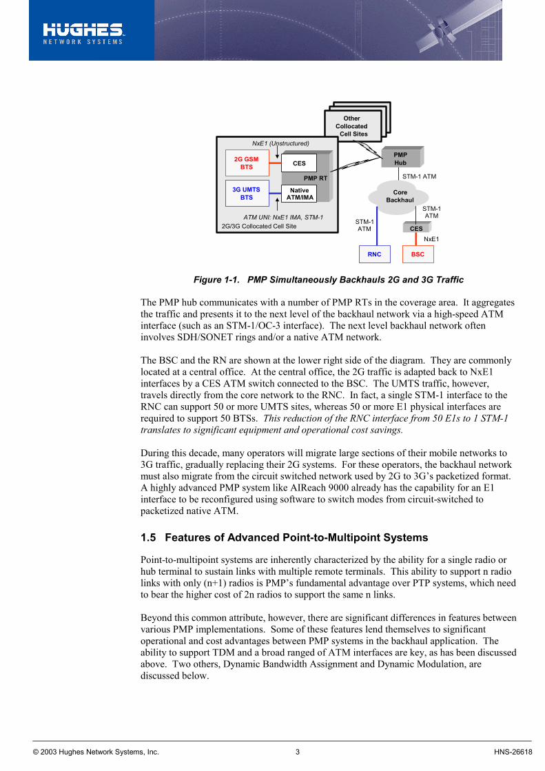
Figure 1-1 represents a PMP system providing the backhaul for a site supporting collocated 3G UMTS and GSM 2G mobility network equipment. The left side of the diagram depicts the cell site with both a 2G BTS and a 3G UMTS RN connected to a single PMP remote terminal (RT). The 2G BTS generates NxE1 interfaces which the PMP network adapts to ATM using CES and CBR QoS. The UMTS RN, however, natively generates a packetized ATM interface (such as E1 UNI, NxE1 IMA, or E3-ATM). This ATM UNI interface carries two PVCs, one for voice and one for data. The same PMP remote terminal could also accommodate potential alternatives such as direct LAN interfaces.
© 2003 Hughes Network Systems, Inc. 3 HNS-26618
OtherCollocated
Cell Sites
PMPHub
CoreBackhaul
2G GSMBTS
3G UMTSBTS
CES
NativeATM/IMA
PMP RT
ATM UNI: NxE1 IMA, STM-12G/3G Collocated Cell Site
NxE1 (Unstructured)
STM-1 ATM
RNC BSC
CES
STM-1ATM
NxE1
STM-1ATM
Figure 1-1. PMP Simultaneously Backhauls 2G and 3G Traffic
The PMP hub communicates with a number of PMP RTs in the coverage area. It aggregates the traffic and presents it to the next level of the backhaul network via a high-speed ATM interface (such as an STM-1/OC-3 interface). The next level backhaul network often involves SDH/SONET rings and/or a native ATM network. The BSC and the RN are shown at the lower right side of the diagram. They are commonly located at a central office. At the central office, the 2G traffic is adapted back to NxE1 interfaces by a CES ATM switch connected to the BSC. The UMTS traffic, however, travels directly from the core network to the RNC. In fact, a single STM-1 interface to the RNC can support 50 or more UMTS sites, whereas 50 or more E1 physical interfaces are required to support 50 BTSs. This reduction of the RNC interface from 50 E1s to 1 STM-1 translates to significant equipment and operational cost savings. During this decade, many operators will migrate large sections of their mobile networks to 3G traffic, gradually replacing their 2G systems. For these operators, the backhaul network must also migrate from the circuit switched network used by 2G to 3G’s packetized format. A highly advanced PMP system like AIReach 9000 already has the capability for an E1 interface to be reconfigured using software to switch modes from circuit-switched to packetized native ATM.
1.5 Features of Advanced Point-to-Multipoint Systems
Point-to-multipoint systems are inherently characterized by the ability for a single radio or hub terminal to sustain links with multiple remote terminals. This ability to support n radio links with only (n+1) radios is PMP’s fundamental advantage over PTP systems, which need to bear the higher cost of 2n radios to support the same n links. Beyond this common attribute, however, there are significant differences in features between various PMP implementations. Some of these features lend themselves to significant operational and cost advantages between PMP systems in the backhaul application. The ability to support TDM and a broad ranged of ATM interfaces are key, as has been discussed above. Two others, Dynamic Bandwidth Assignment and Dynamic Modulation, are discussed below.
© 2003 Hughes Network Systems, Inc. 4 HNS-26618
1.6 Dynamic Bandwidth Assignment
Dynamic Bandwidth Assignment (DBA) methods are widely deployed in the core of many data networks. Traffic typically reaches the network core over wireline E1/T1 connections, but once within the core it can be transported at the channel capacity of the backbone, often 155 Mbps. PMP systems using TDM/TDMA (time division multiple access) can also support DBA. These systems enable any remote terminal to receive and transmit up to the maximum channel capacity in the access network. (This is why, for example, PMP systems with native LAN or 155 Mbps interfaces at the remote terminal can offer speed and bursting capabilities that wireline approaches cannot provide.) DBA takes advantage of a MAC signaling layer to effectively move bandwidth between remote terminals within the same radio-channel with a minimum of delay. In some cases, the downlink (hub to remote direction) PMP link is a broadcast link and the remote terminals use filtering to determine the traffic intended for them. In this case, almost no MAC layer signaling is required to shift air bandwidth between remote terminals in the downlink. Implementing a good DBA algorithm with a minimal amount of delay in a radio system is very complex. Backed by 25 years of experience, the AIReach 9000 system operates extremely efficiently with very low delay (less than 0.1 millisecond) and low overhead. The DBA algorithms, however, are only available when the PMP system supports packetized native ATM interfaces and oversubscription. DBA algorithms offer no advantage for traffic that requires committed bandwidth at all times, such as TDM or CES-CBR traffic. By contrast, VBR services for ATM or IP allow for a small committed component and a larger best-effort component. The bandwidth for the best-effort component is the bandwidth available for statistical multiplexing and thus for DBA.
1.7 Dynamic Modulation
The effect of Dynamic Modulation is to increase the average capacity of a PMP system. With Dynamic Modulation, each PMP radio link operates at the highest order modulation (such as 64-QAM) that can be supported by the immediate channel conditions. For line-of-sight millimeter-wave communications systems, the dominating factor for radio link quality is the attenuation due to rain fades. Clear sky conditions permit the use of higher order of modulations than can be supported during rain fades. Depending upon the rain zone for a given area, the higher order modulation can be utilized at least 99% of the time. In turn, the corresponding higher capacity can be achieved 99% of the time. It follows that during less than 1% of the time, the modulation must be of a lower order (such as QPSK) to guarantee a given BER rate such as 10-8. Dynamic Modulation is particularly effective when applied to VBR services (such as IP-data services) where only a small portion of the bandwidth is guaranteed at all times, and a large portion of the bandwidth is a best-effort service. The MAC layer manages the change in the modulation similarly to the way the power control messaging is handled. As the rain fade deepens, the MAC layer signals to the remotes to change the modulation. The algorithms used to determine the optimal modulation for a link use C/I, BER, and other signal quality measures. If Dynamic Modulation is to be effective, the MAC layer must be able to adjust the modulation faster than the onset of a rain fade. To have confidence that this is the case, we have to look at data collected during actual rain fades.

© 2003 Hughes Network Systems, Inc. 5 HNS-26618
The data presented in Figure 1-2 was collected August 29, 2001 in Mumbai, India by an AIReach 9000 system operating at 26 GHz. (This data is courtesy of Hughes Telecom India, Ltd.) The data was captured at a hub terminal radio receiver in 15-second increments over a 24-hour period. The receive signal strength is the average received signal strength during the 15-second period. The graph is divided into three sections by two horizontal lines at –69 dBm and –76 dBm, which are typical 64-QAM and 16-QAM operating thresholds for PMP systems. The upper left plot shows that the receive signal strength varied throughout the entire 24-hour period within a small range of about –66 dBm to –70 dBm, except for two deep fades near 3:30 a.m. and 4:00 a.m. These deep fades correspond to periods of heavy rainfall. The lower left plot shows the slope of the attenuation plot. Notice that the slope never exceeds 0.4 dB/second. The plots on the right are an enlargement of the second deep rain fade. The scale for these two plots is 72 minutes.
15:00 18:00 21:00 00:00 03:00 06:00 09:00 12:00 15:00
RSSI vs. Time
RSSI(dBm)
Time of DayRSSI Rate of Change vs. Time
RSSIRate ofChange(dB perSecond)
Time of Day
12:00
12:00 15:00 18:00 21:00 00:00 03:00 06:00 09:00 12:00 15:00
0.4
0.2
0.0
0.2
-64-66-68-70-72-74-76-78-80-82
RSSI vs. Time
RSSI(dBm)
72 Minutes
RSSI Rate of Change vs. Time
RSSI Rate of Change(dB perSecond)
72 Minutes
-64
-66
-68
-70
-72
-74
-76
-78
-80
-82
0.4
0.0
0.2
0.2
Figure 1-2. Rain Data This data shows that the MAC layer must be able to change the modulation within 1 or 2 seconds when using a trigger point that is 1 dB above the signal strength threshold. This requirement is within the capabilities of a well-designed and executed PMP system. We have now seen that advanced PMP systems, based on TDMA and with their ability to carry native TDM and IP/ATM payloads, are well suited to address the backhaul needs of both 2G and 3G mobile systems. For 3G applications, advanced PMP systems offer “payload-aware” transport so that they work with and enhance the 3G network. Increases in data being carried by 3G systems means that PMP systems must be able to address these needs with native ATM and IP interfaces and advanced capabilities such as handling ATM service classes, efficient Dynamic Bandwidth Allocation, and Dynamic Modulation. Key benefits of these include:
• Greater spectral efficiency and less total spectrum required • Fewer radios and associated multiplexing equipment • Lower overall capital and operational costs
Let’s examine these benefits in light of a comparison of PMP and PTP approaches for mobile backhaul.
© 2003 Hughes Network Systems, Inc. 6 HNS-26618
1.8 Comparison of Point-to-Multipoint and Point-to-Point Backhaul Approaches
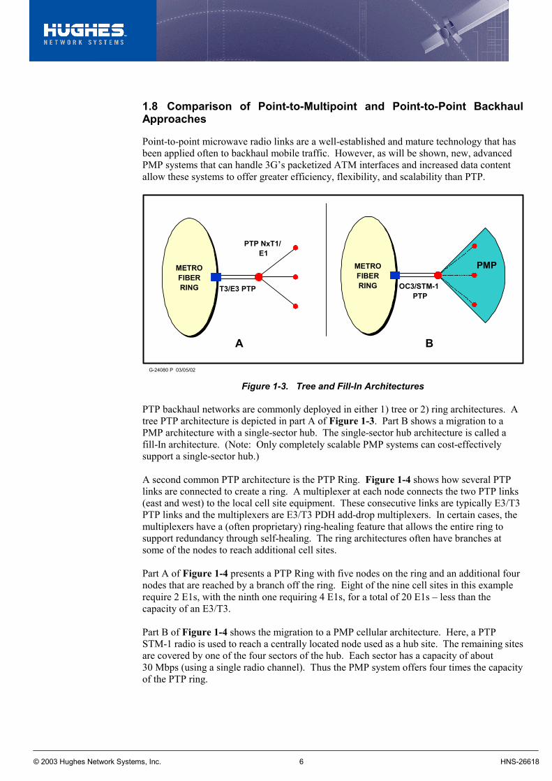
Point-to-point microwave radio links are a well-established and mature technology that has been applied often to backhaul mobile traffic. However, as will be shown, new, advanced PMP systems that can handle 3G’s packetized ATM interfaces and increased data content allow these systems to offer greater efficiency, flexibility, and scalability than PTP.
A B
METROFIBERRING OC3/STM-1
PTP
PMPMETROFIBERRING T3/E3 PTP
PTP NxT1/E1
G-24080 P 03/05/02 Figure 1-3. Tree and Fill-In Architectures
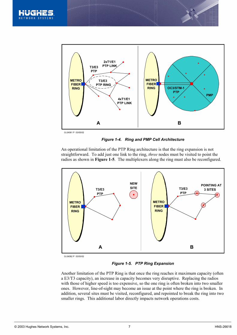
PTP backhaul networks are commonly deployed in either 1) tree or 2) ring architectures. A tree PTP architecture is depicted in part A of Figure 1-3. Part B shows a migration to a PMP architecture with a single-sector hub. The single-sector hub architecture is called a fill-In architecture. (Note: Only completely scalable PMP systems can cost-effectively support a single-sector hub.) A second common PTP architecture is the PTP Ring. Figure 1-4 shows how several PTP links are connected to create a ring. A multiplexer at each node connects the two PTP links (east and west) to the local cell site equipment. These consecutive links are typically E3/T3 PTP links and the multiplexers are E3/T3 PDH add-drop multiplexers. In certain cases, the multiplexers have a (often proprietary) ring-healing feature that allows the entire ring to support redundancy through self-healing. The ring architectures often have branches at some of the nodes to reach additional cell sites. Part A of Figure 1-4 presents a PTP Ring with five nodes on the ring and an additional four nodes that are reached by a branch off the ring. Eight of the nine cell sites in this example require 2 E1s, with the ninth one requiring 4 E1s, for a total of 20 E1s – less than the capacity of an E3/T3. Part B of Figure 1-4 shows the migration to a PMP cellular architecture. Here, a PTP STM-1 radio is used to reach a centrally located node used as a hub site. The remaining sites are covered by one of the four sectors of the hub. Each sector has a capacity of about 30 Mbps (using a single radio channel). Thus the PMP system offers four times the capacity of the PTP ring.
© 2003 Hughes Network Systems, Inc. 7 HNS-26618
G-24081 P 03/05/02
T3/E3PTP
T3/E3PTP RING
2xT1/E1PTP LINK
4xT1/E1PTP LINK
METROFIBERRING
A B
PMP
METROFIBERRING OC3/STM-1
PTP
Figure 1-4. Ring and PMP Cell Architecture
An operational limitation of the PTP Ring architecture is that the ring expansion is not straightforward. To add just one link to the ring, three nodes must be visited to point the radios as shown in Figure 1-5. The multiplexers along the ring must also be reconfigured.
G-24082 P 03/05/02
A
T3/E3PTP
METROFIBERRING
T3/E3PTP
METROFIBERRING
NEWSITE
POINTING AT3 SITES
B
Figure 1-5. PTP Ring Expansion
Another limitation of the PTP Ring is that once the ring reaches it maximum capacity (often a E3/T3 capacity), an increase in capacity becomes very disruptive. Replacing the radios with those of higher speed is too expensive, so the one ring is often broken into two smaller ones. However, line-of-sight may become an issue at the point where the ring is broken. In addition, several sites must be visited, reconfigured, and repointed to break the ring into two smaller rings. This additional labor directly impacts network operations costs.
© 2003 Hughes Network Systems, Inc. 8 HNS-26618
By contrast, the PMP architecture supports expansion of the network very efficiently in a linear fashion. Each remote site is installed incrementally once the hub site is installed. Adding a remote requires only a visit to that remote site, thus reducing the site visits from three for PTP to one for PMP. Once a sector has reached its capacity, a second channel can be added to the sector at the hub site without affecting the existing services. No site visit is required for capacity to be added to a remote site or moved from one remote site to another. Capacity is added through a software reconfiguration. The flexibility of incremental expansion of the PMP system contrasts with the lack of scalability of PTP architectures, which is a key advantage of PMP that gives operators the flexibility they need as they expand their networks.
1.9 3G Radio Node Spacing Versus Point-to-Multipoint Sector Size
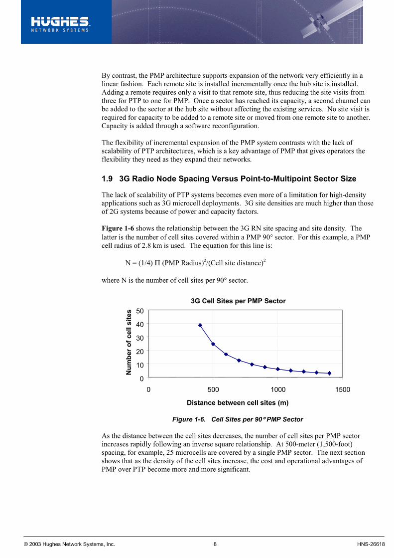
The lack of scalability of PTP systems becomes even more of a limitation for high-density applications such as 3G microcell deployments. 3G site densities are much higher than those of 2G systems because of power and capacity factors. Figure 1-6 shows the relationship between the 3G RN site spacing and site density. The latter is the number of cell sites covered within a PMP 90° sector. For this example, a PMP cell radius of 2.8 km is used. The equation for this line is: N = (1/4) Π (PMP Radius)2/(Cell site distance)2
where N is the number of cell sites per 90° sector.
3G Cell Sites per PMP Sector
0
10
20
30
40
50
0 500 1000 1500
Distance between cell sites (m)
Num
ber o
f cel
l site
s
Figure 1-6. Cell Sites per 90°°°° PMP Sector
As the distance between the cell sites decreases, the number of cell sites per PMP sector increases rapidly following an inverse square relationship. At 500-meter (1,500-foot) spacing, for example, 25 microcells are covered by a single PMP sector. The next section shows that as the density of the cell sites increase, the cost and operational advantages of PMP over PTP become more and more significant.
© 2003 Hughes Network Systems, Inc. 9 HNS-26618
1.10 Cost Model
The scalability of the PMP architecture translates into cost savings as the number of sites increases. As shown in Figure 1-6, the cell site density increases rapidly as the distance between sites decreases. The simple cost model described below compares the cost of PMP and PTP systems for various cell site densities. The results are that as the cell site density increases, the PMP system’s cost advantage over PTP also increases. The model is based on the following assumptions, using estimated typical industry pricing models with costs in US$. PTP Assumptions:
• PTP Per-Radio cost = $5,000.
• E3 Multiplexing cost = $5,000 (required at 75% of sites).
• Fiber Ring Multiplexing cost = $5,000.
• Each site requires 4 E1s.
• Each PTP Ring supports up to an E3 of capacity.
• Each PTP Ring requires a PTP link back to the fiber core.
• Site visit cost = $1,500.
• On average, 2.5 site visits are required per PTP link installation. (Refer to explanation in the previous section on PTP Ring expansion.)
PMP Assumptions:
• PMP Hub cost = $192K.
• PMP Sector cost = $48K (25% of total hub cost).
• PMP RT cost = $5K.
• Site visit cost = $1,500.
• On average, 1.2 site visits are required per PMP link installation. (The 0.2 factor is added to account for the hub installation cost.)
• For the concentrated model, 40% of the traffic is voice traffic, and 80% of that traffic is carried; 60% of the total traffic is data, and 20% of that traffic is carried.
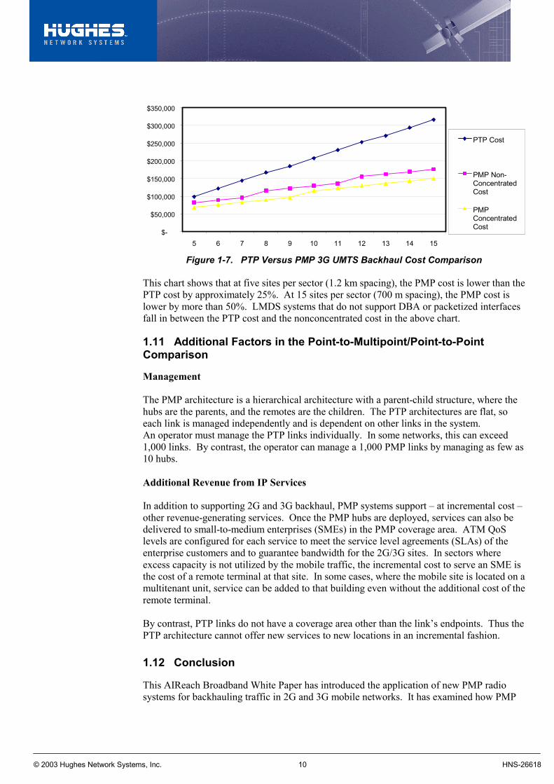
Figure 1-7 presents the results based on these parameters. The concentrated PMP model takes advantage of the statistical gains achieved by a PMP system with the use of oversubscription and Dynamic Bandwidth Allocation and Dynamic Modulation.
© 2003 Hughes Network Systems, Inc. 10 HNS-26618
$-
$50,000
$100,000
$150,000
$200,000
$250,000
$300,000
$350,000
5 6 7 8 9 10 11 12 13 14 15
PTP Cost
PMP Non-ConcentratedCost
PMPConcentratedCost
Figure 1-7. PTP Versus PMP 3G UMTS Backhaul Cost Comparison
This chart shows that at five sites per sector (1.2 km spacing), the PMP cost is lower than the PTP cost by approximately 25%. At 15 sites per sector (700 m spacing), the PMP cost is lower by more than 50%. LMDS systems that do not support DBA or packetized interfaces fall in between the PTP cost and the nonconcentrated cost in the above chart.
1.11 Additional Factors in the Point-to-Multipoint/Point-to-Point Comparison
Management The PMP architecture is a hierarchical architecture with a parent-child structure, where the hubs are the parents, and the remotes are the children. The PTP architectures are flat, so each link is managed independently and is dependent on other links in the system. An operator must manage the PTP links individually. In some networks, this can exceed 1,000 links. By contrast, the operator can manage a 1,000 PMP links by managing as few as 10 hubs. Additional Revenue from IP Services In addition to supporting 2G and 3G backhaul, PMP systems support – at incremental cost – other revenue-generating services. Once the PMP hubs are deployed, services can also be delivered to small-to-medium enterprises (SMEs) in the PMP coverage area. ATM QoS levels are configured for each service to meet the service level agreements (SLAs) of the enterprise customers and to guarantee bandwidth for the 2G/3G sites. In sectors where excess capacity is not utilized by the mobile traffic, the incremental cost to serve an SME is the cost of a remote terminal at that site. In some cases, where the mobile site is located on a multitenant unit, service can be added to that building even without the additional cost of the remote terminal. By contrast, PTP links do not have a coverage area other than the link’s endpoints. Thus the PTP architecture cannot offer new services to new locations in an incremental fashion.
1.12 Conclusion
This AIReach Broadband White Paper has introduced the application of new PMP radio systems for backhauling traffic in 2G and 3G mobile networks. It has examined how PMP
© 2003 Hughes Network Systems, Inc. 11 HNS-26618
systems offer cost-effective and revenue-generating capabilities unmatched by the PTP and leased line solutions currently implemented. The paper detailed the reasons why, and the technology associated with how, the 3G and PMP synergies result in systems offering cost savings, greater efficiency, and easier management than can be attained with fixed-assignment PTP systems. These benefits are byproducts of the packetized interface for the backhaul interfaces of the 3G RNs and the packetized nature of advanced PMP systems. For an operator to fully realize the benefits offered by a PMP system, certain important features are required including:
• Native ATM UNI Interfaces (E1-ATM/IMA, STM-1/E3 ATM)
• Native IP Interfaces (10/100BaseT Ethernet)
• TDM/TDMA Air Interface
• Full ATM QoS support (CBR, VBRrt, VBRnrt, and UBR)
• Dynamic Bandwidth Assignment (DBA)
• Dynamic Modulation with Multi-modulation
• Single Sector Hub
• High Performance IP Services PMP systems with these features give operators several degrees of freedom in implementations that result in many advantages over PTP systems for UMTS backhaul networks. AIReach, AIRmatch Dynamic Modulation Matching, AIRfill Dynamic Bandwidth Allocation, and AIRange Coverage Extension technology are registered trademarks of Hughes Electronics Corporation.


![Point-to-Multipoint and Multipoint-to-Multipoint · PDF filedefined by IEEE 802.1Qay [2] is representative carrier Ethernet . Abstract — We have implemented point-to-multipoint (PtMP)](https://img.pdfslide.net/doc/110x75/5a75c0147f8b9a4b538cb6cd/point-to-multipoint-and-multipoint-to-multipoint-defined-by-ieee-8021qay.jpg)