Embed Size (px)
Citation preview
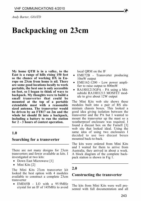
My home QTH is in a valley, to theEast is a range of hills rising 150 feetso the chance of working DX in Eu-rope on 23cm from home is nil. Thereare some good locations locally to workportable, the best one is only accessibleon foot, so I began to think of ways tobackpack. My thoughts were to build asmall transverter that could bemounted at the top of a portableextendable mast with a reasonablesized antenna. The transverter wouldbe driven by an FT817 on 2m and thewhole lot should fit into a backpack,including a battery to run the stationfor 2 - 3 hours of contest operation.
1.0Searching for a transverter
There are not many designs for 23cmtransverters and fewer available as kits. Iinvestigated at two kits: • Down East Microwave [1] • Mini Kits [2]
The Mini Kits 23cm transverter kitlooked the best option with 4 modulesavailable to construct a complete 23cmtransverter • EME65B - LO with a 95.9MHz
crystal for an IF of 145MHz to avoid
local QRM on the IF • EME72B - Transverter producing
10mW output • EME162-1200 - Low power ampli-
fier to raise output to 800mW • RA18H1213GPA - PA using a Mit-
subishi RA18H1213 MOSFET mod-ule to give about 12W output
The Mini Kits web site shows thesemodules built into a pair of RS alu-minium chassis boxes. This looked agood idea giving isolation between thetransverter and the PA but I wanted tomount the transverter up the mast so aweatherproof enclosure was required. Ifound a diecast box on the Farnell [3]web site that looked ideal. Using thesame idea of using two enclosures Idecided to use two diecast boxesmounted back-to-back.The kits were ordered from Mini Kitsand I waited for them to arrive fromAustralia, they arrived in about a week.A block diagram of the complete back-pack station is shown in Fig 1.
2.0Constructing the transverter
The kits from Mini Kits were well pre-sented with full documentation and all
Backpacking on 23cm
Andy Barter, G8ATD
VHF COMMUNICATIONS 4/2010
243
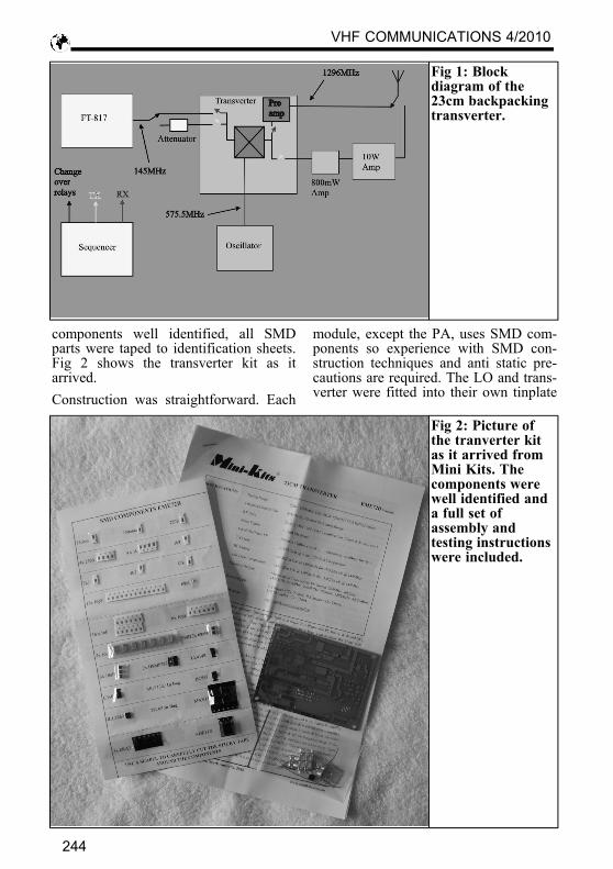
components well identified, all SMDparts were taped to identification sheets.Fig 2 shows the transverter kit as itarrived.Construction was straightforward. Each
module, except the PA, uses SMD com-ponents so experience with SMD con-struction techniques and anti static pre-cautions are required. The LO and trans-verter were fitted into their own tinplate
Fig 1: Blockdiagram of the23cm backpackingtransverter.
Fig 2: Picture ofthe tranverter kitas it arrived fromMini Kits. Thecomponents werewell identified anda full set ofassembly andtesting instructionswere included.
VHF COMMUNICATIONS 4/2010
244
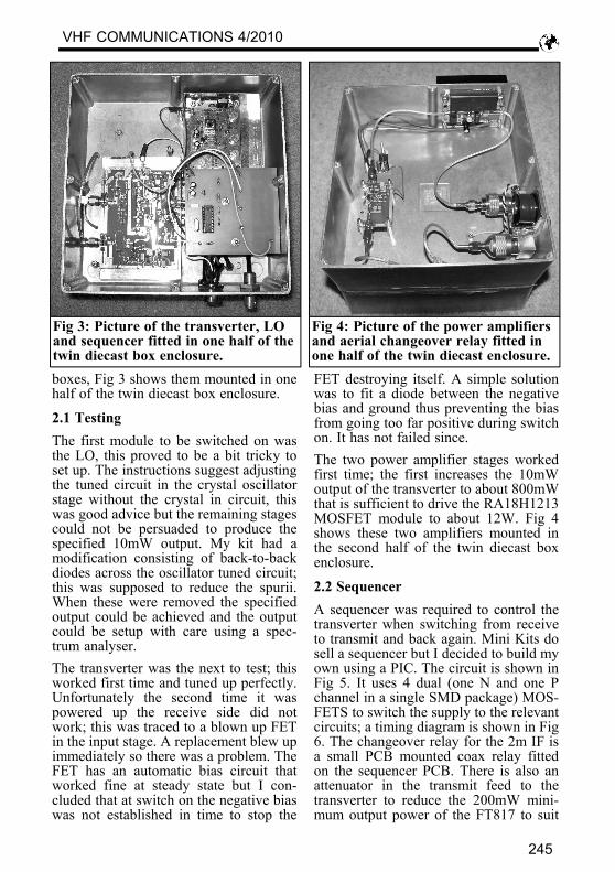
boxes, Fig 3 shows them mounted in onehalf of the twin diecast box enclosure.
2.1 TestingThe first module to be switched on wasthe LO, this proved to be a bit tricky toset up. The instructions suggest adjustingthe tuned circuit in the crystal oscillatorstage without the crystal in circuit, thiswas good advice but the remaining stagescould not be persuaded to produce thespecified 10mW output. My kit had amodification consisting of back-to-backdiodes across the oscillator tuned circuit;this was supposed to reduce the spurii.When these were removed the specifiedoutput could be achieved and the outputcould be setup with care using a spec-trum analyser.The transverter was the next to test; thisworked first time and tuned up perfectly.Unfortunately the second time it waspowered up the receive side did notwork; this was traced to a blown up FETin the input stage. A replacement blew upimmediately so there was a problem. TheFET has an automatic bias circuit thatworked fine at steady state but I con-cluded that at switch on the negative biaswas not established in time to stop the
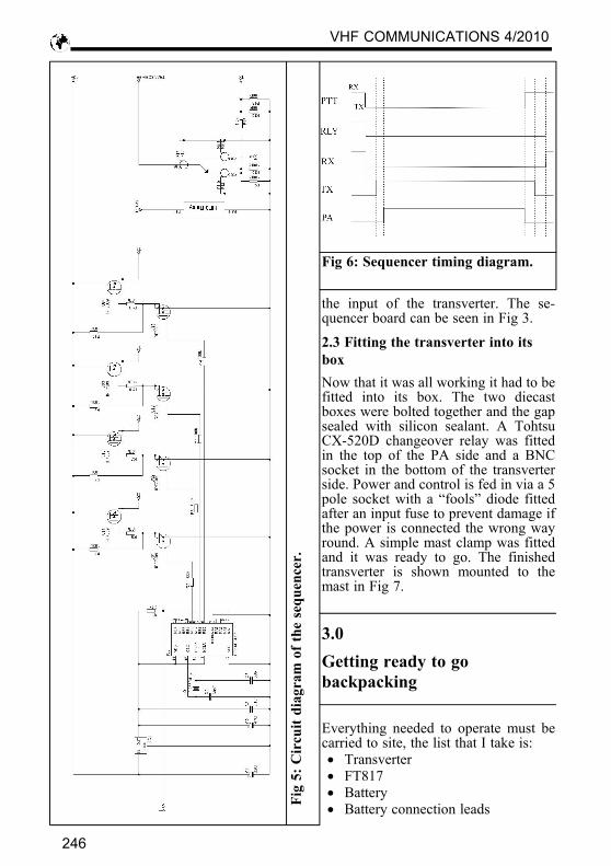
FET destroying itself. A simple solutionwas to fit a diode between the negativebias and ground thus preventing the biasfrom going too far positive during switchon. It has not failed since.The two power amplifier stages workedfirst time; the first increases the 10mWoutput of the transverter to about 800mWthat is sufficient to drive the RA18H1213MOSFET module to about 12W. Fig 4shows these two amplifiers mounted inthe second half of the twin diecast boxenclosure.
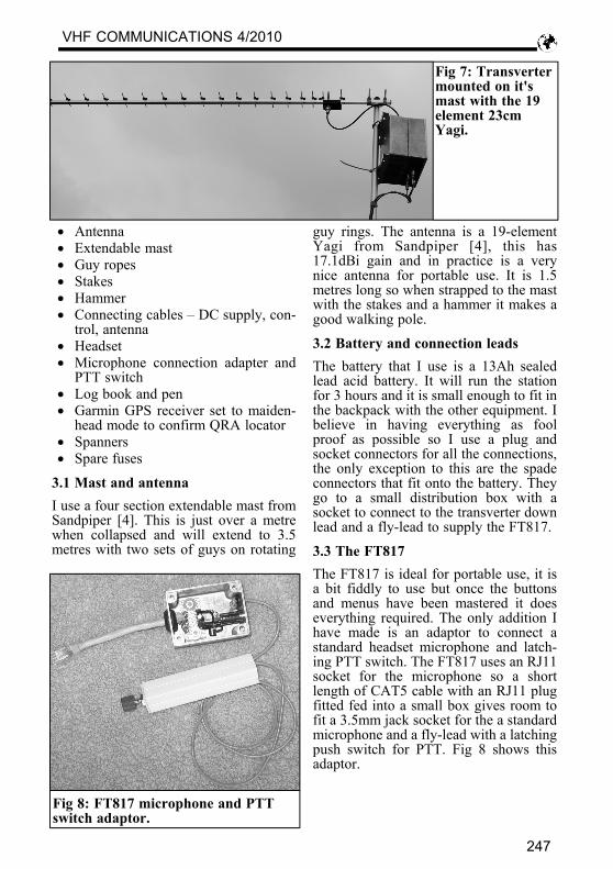
2.2 SequencerA sequencer was required to control thetransverter when switching from receiveto transmit and back again. Mini Kits dosell a sequencer but I decided to build myown using a PIC. The circuit is shown inFig 5. It uses 4 dual (one N and one Pchannel in a single SMD package) MOS-FETS to switch the supply to the relevantcircuits; a timing diagram is shown in Fig6. The changeover relay for the 2m IF isa small PCB mounted coax relay fittedon the sequencer PCB. There is also anattenuator in the transmit feed to thetransverter to reduce the 200mW mini-mum output power of the FT817 to suit
Fig 3: Picture of the transverter, LOand sequencer fitted in one half of thetwin diecast box enclosure.
Fig 4: Picture of the power amplifiersand aerial changeover relay fitted inone half of the twin diecast enclosure.
VHF COMMUNICATIONS 4/2010
245
the input of the transverter. The se-quencer board can be seen in Fig 3.
2.3 Fitting the transverter into itsboxNow that it was all working it had to befitted into its box. The two diecastboxes were bolted together and the gapsealed with silicon sealant. A TohtsuCX-520D changeover relay was fittedin the top of the PA side and a BNCsocket in the bottom of the transverterside. Power and control is fed in via a 5pole socket with a “fools” diode fittedafter an input fuse to prevent damage ifthe power is connected the wrong wayround. A simple mast clamp was fittedand it was ready to go. The finishedtransverter is shown mounted to themast in Fig 7.
3.0Getting ready to gobackpacking
Everything needed to operate must becarried to site, the list that I take is: • Transverter • FT817 • Battery • Battery connection leads
Fig 6: Sequencer timing diagram.
F
ig 5
: Cir
cuit
diag
ram
of t
he s
eque
ncer
.
VHF COMMUNICATIONS 4/2010
246
• Antenna • Extendable mast • Guy ropes • Stakes • Hammer • Connecting cables – DC supply, con-
trol, antenna • Headset • Microphone connection adapter and
PTT switch • Log book and pen • Garmin GPS receiver set to maiden-
head mode to confirm QRA locator • Spanners • Spare fuses
3.1 Mast and antennaI use a four section extendable mast fromSandpiper [4]. This is just over a metrewhen collapsed and will extend to 3.5metres with two sets of guys on rotating
guy rings. The antenna is a 19-elementYagi from Sandpiper [4], this has17.1dBi gain and in practice is a verynice antenna for portable use. It is 1.5metres long so when strapped to the mastwith the stakes and a hammer it makes agood walking pole.
3.2 Battery and connection leadsThe battery that I use is a 13Ah sealedlead acid battery. It will run the stationfor 3 hours and it is small enough to fit inthe backpack with the other equipment. Ibelieve in having everything as foolproof as possible so I use a plug andsocket connectors for all the connections,the only exception to this are the spadeconnectors that fit onto the battery. Theygo to a small distribution box with asocket to connect to the transverter downlead and a fly-lead to supply the FT817.
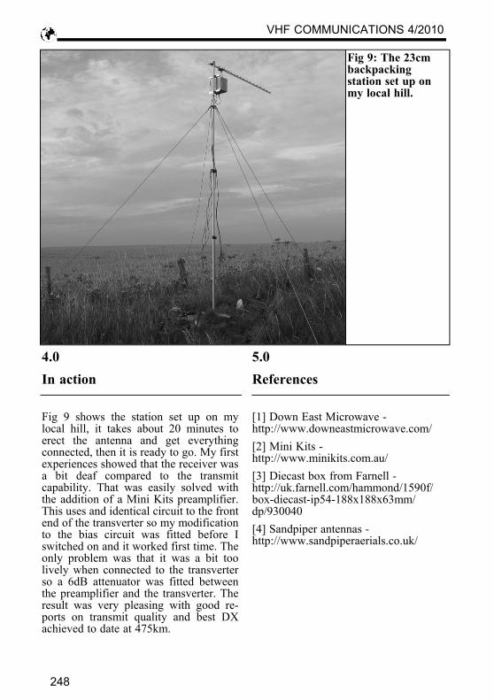
3.3 The FT817The FT817 is ideal for portable use, it isa bit fiddly to use but once the buttonsand menus have been mastered it doeseverything required. The only addition Ihave made is an adaptor to connect astandard headset microphone and latch-ing PTT switch. The FT817 uses an RJ11socket for the microphone so a shortlength of CAT5 cable with an RJ11 plugfitted fed into a small box gives room tofit a 3.5mm jack socket for the a standardmicrophone and a fly-lead with a latchingpush switch for PTT. Fig 8 shows thisadaptor.
Fig 7: Transvertermounted on it'smast with the 19element 23cmYagi.
Fig 8: FT817 microphone and PTTswitch adaptor.
VHF COMMUNICATIONS 4/2010
247
4.0In action
Fig 9 shows the station set up on mylocal hill, it takes about 20 minutes toerect the antenna and get everythingconnected, then it is ready to go. My firstexperiences showed that the receiver wasa bit deaf compared to the transmitcapability. That was easily solved withthe addition of a Mini Kits preamplifier.This uses and identical circuit to the frontend of the transverter so my modificationto the bias circuit was fitted before Iswitched on and it worked first time. Theonly problem was that it was a bit toolively when connected to the transverterso a 6dB attenuator was fitted betweenthe preamplifier and the transverter. Theresult was very pleasing with good re-ports on transmit quality and best DXachieved to date at 475km.
5.0References
[1] Down East Microwave -http://www.downeastmicrowave.com/[2] Mini Kits -http://www.minikits.com.au/[3] Diecast box from Farnell -http://uk.farnell.com/hammond/1590f/box-diecast-ip54-188x188x63mm/dp/930040[4] Sandpiper antennas -http://www.sandpiperaerials.co.uk/
Fig 9: The 23cmbackpackingstation set up onmy local hill.
VHF COMMUNICATIONS 4/2010
248