Embed Size (px)
Citation preview
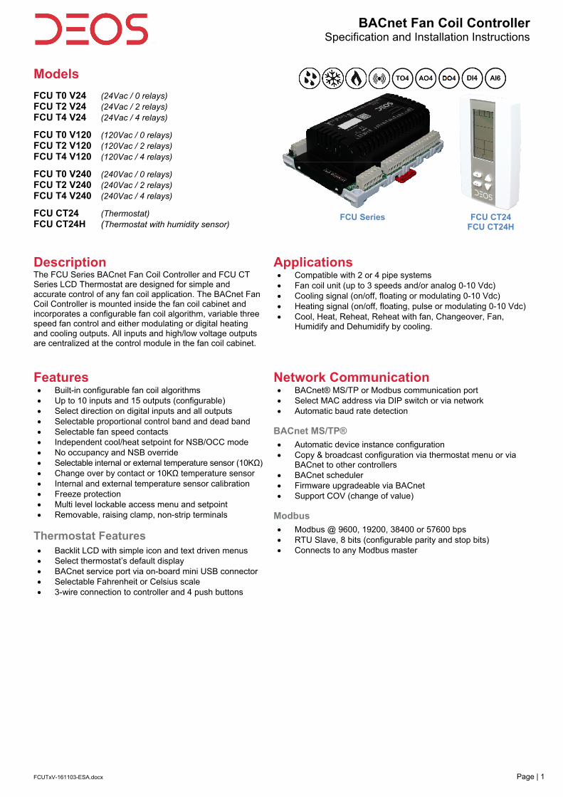
BACnet Fan Coil ControllerSpecification and Installation Instructions
FCUTxV-161103-ESA.docx Page | 1
Models
FCU T0 V24 (24Vac / 0 relays) FCU T2 V24 (24Vac / 2 relays) FCU T4 V24 (24Vac / 4 relays)
FCU T0 V120 (120Vac / 0 relays) FCU T2 V120 (120Vac / 2 relays) FCU T4 V120 (120Vac / 4 relays)
FCU T0 V240 (240Vac / 0 relays) FCU T2 V240 (240Vac / 2 relays) FCU T4 V240 (240Vac / 4 relays)
FCU CT24 (Thermostat) FCU CT24H (Thermostat with humidity sensor)
FCU Series
FCU CT24
FCU CT24H
Description The FCU Series BACnet Fan Coil Controller and FCU CT Series LCD Thermostat are designed for simple and accurate control of any fan coil application. The BACnet Fan Coil Controller is mounted inside the fan coil cabinet and incorporates a configurable fan coil algorithm, variable three speed fan control and either modulating or digital heating and cooling outputs. All inputs and high/low voltage outputs are centralized at the control module in the fan coil cabinet.
Applications Compatible with 2 or 4 pipe systems Fan coil unit (up to 3 speeds and/or analog 0-10 Vdc) Cooling signal (on/off, floating or modulating 0-10 Vdc) Heating signal (on/off, floating, pulse or modulating 0-10 Vdc) Cool, Heat, Reheat, Reheat with fan, Changeover, Fan,
Humidify and Dehumidify by cooling.
Features Built-in configurable fan coil algorithms Up to 10 inputs and 15 outputs (configurable) Select direction on digital inputs and all outputs Selectable proportional control band and dead band Selectable fan speed contacts Independent cool/heat setpoint for NSB/OCC mode No occupancy and NSB override Selectable internal or external temperature sensor (10KΩ) Change over by contact or 10KΩ temperature sensor Internal and external temperature sensor calibration Freeze protection Multi level lockable access menu and setpoint Removable, raising clamp, non-strip terminals
Thermostat Features Backlit LCD with simple icon and text driven menus Select thermostat’s default display BACnet service port via on-board mini USB connector Selectable Fahrenheit or Celsius scale 3-wire connection to controller and 4 push buttons
Network Communication BACnet® MS/TP or Modbus communication port Select MAC address via DIP switch or via network Automatic baud rate detection
BACnet MS/TP®
Automatic device instance configuration Copy & broadcast configuration via thermostat menu or via
BACnet to other controllers BACnet scheduler Firmware upgradeable via BACnet Support COV (change of value)
Modbus
Modbus @ 9600, 19200, 38400 or 57600 bps RTU Slave, 8 bits (configurable parity and stop bits) Connects to any Modbus master

BACnet Fan Coil ControllerSpecification and Installation Instructions
www.deos-controls.com Page | 2
Controller Specifications
Description FCU T0 V24 FCU T2 V24 FCU T4 V24
FCU T0 V120FCU T2 V120 FCU T4 V120
FCU T0 V240FCU T2 V240 FCU T4 V240
Inputs
2 fixed analog inputs (external temp. and changeover sensors); 10KΩ or contact 4 analog inputs (0-10 Vdc or 10 KΩ via DIP switches) 3 configurable digital inputs 1 night set back or occupancy sensor input
Outputs 4 analog , 0-10 Vdc configurable outputs (changeover/cooling/heating, fan, humidity) 4 configurable TRIAC outputs (changeover/cooling/heating) 3 speed fan (5A contacts); configurable up to 3 speeds 0, 2 or 4 configurable digital outputs (changeover/cooling/heating, humidity, 3A dry contact)
Power supply 24 Vac 120 Vac 240 Vac
Power consumption 8 VA max. 24 Vac thermal fused.
BACnet BACnet® MS/TP @ 9600, 19200, 38400 or 76800 bps (BAS-C)
Modbus
Modbus RTU slave @ 9600, 19200, 38400 or 57600. Selectable parity and stop bit configuration: No parity, 2 stop bit Even parity, 1 stop bit Odd parity, 1 stop bit
Communication Connections
24 AWG twisted-shield cable (Belden 9841 or equivalent)
Electrical Connections 0.8 mm2 [18 AWG] minimum
Operating temperature 0ºC to 50ºC [32ºF to 122ºF]
Storage temperature -30ºC to 50ºC [-22ºF to 122ºF]
Relative Humidity 5 to 95% non condensing
Enclosure protection IP 30 (EN 60529)
Weight 635 g. [1.4 lb]
Dimensions: A = 6.30” | 160mm B = 5.00” | 126mm C = 2.25” | 57mm
Thermostat Specifications Description FCU CT24 FCU CT24H
Sensor Temperature Temperature and Humidity
Setpoint range 10ºC to 40ºC [50ºF to 104ºF] 10ºC to 40ºC [50ºF to 104ºF] | 10 to 65%RH
Control accuracy ±0.5ºC [0.9ºF] @ 22ºC [71.6ºF] typical calibrated ±0.5ºC [0.9ºF] @ 22ºC [71.6ºF] | ±3.5% RH
Display resolution ±0.1ºC [0.2ºF] 0.1%
Electrical connection 3 wires to the controller and 2 wires (optional) to BACnet network service port
0.8 mm2 [18 AWG] minimum
BACnet service port Mini USB connector
Power supply 24Vac or 24Vdc
Power consumption 1VA
Operating temperature 0ºC to 50ºC [32ºF to 122ºF]
Storage temperature -30ºC to 50ºC [-22ºF to 122ºF]
Relative humidity 5 to 95 % non condensing
Enclosure protection IP 30 (EN 60529)
Weight 120 g. [0.25 lb]
Dimensions A = 2.85” | 73mm B = 4.85” | 123mm C = 1.00” | 24mm D = 2.36” | 60mm E = 3.27” | 83mm
Note The FCU CT thermostat functions only with the FCU Tx controller. All the inputs/outputs are located on the FCU Tx except for the temperature/humidity sensor built-in the FCU CT.
B
A C
A
B
C
DE
ºF / º C

BACnet Fan Coil ControllerSpecification and Installation Instructions
www.deos-controls.com Page | 3
Interface
Cooling ON A: Automatic
Communication Status
Alarm status
Heating ON A: Automatic
Menu set-up Lock
Energy saving mode
Fan ON A: Automatic
Programming mode (Technician setting)
Percentage of humidity
Humidity ON 33, 66 or 100% output
Dehumidification ON 33, 66 or 100% output or
ºC: Celsius scale ºF: Fahrenheit scale
Mounting Instructions CAUTION: Remove power to avoid a risk of malfunction.
A. Remove the captive screw that’s holding the base and the front cover of the unit together. B. Lift the front cover of the unit to separate it from the base. C. Pull all wires through the holes in the base. D. Secure the base to the wall using wall anchors and screws (supplied). Make the appropriate connections. E. Mount the control module on the base and secure using the screw.
BACnet or Modbus Address DIP Switch (DS2) MAC address for communication, are selectable by DIP switch using binary logic. If you do not change device instance in program mode, it will be automatically modified according to the MAC address.
Note: Avoid using addresses above 246 when selecting Modbus MAC address.
MAC Address DS.1 = 1 DS.2 = 2 DS.3 = 4 DS.4 = 8 DS.5 = 16 DS.6 = 32 DS.7 = 64 DS.8 = 128 Default Device Instance
0 OFF OFF OFF OFF OFF OFF OFF OFF 153000
1 ON OFF OFF OFF OFF OFF OFF OFF 153001
2 OFF ON OFF OFF OFF OFF OFF OFF 153002
3 ON ON OFF OFF OFF OFF OFF OFF 153003
4 OFF OFF ON OFF OFF OFF OFF OFF 153004
… … … … … … … … … …
126 OFF ON ON ON ON ON ON OFF 153126
127 ON ON ON ON ON ON ON OFF 153127
* Slave addresses available by setting DS.8 to ON
CF
%RH
MO TU WE TH FR SA SU
AM PM
....
%RH
C F
A
EDCB
BACnet Fan Coil ControllerSpecification and Installation Instructions
www.deos-controls.com Page | 4
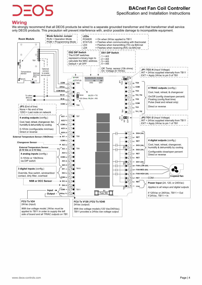
Wiring We strongly recommend that all DEOS products be wired to a separate grounded transformer and that transformer shall service only DEOS products. This precaution will prevent interference with, and/or possible damage to incompatible equipment.
ON
1 2 3 4 5 6 7 8
ON
1 2 3 4
DS2 DS1
Fuse 10AF1
TB1
PG
MR
UN
1234567
Room Module
TemperatureSensor BACnet
ServicePort
12
3
Mode Selector JumperRUN = Operation ModePGM = Programming Mode
24Vac
COM
COM BUS
IN B-
IN A+
COM
3
DS1 DIP Switch
1 = AI32 = AI43 = AI54 = AI6
Off: Temp. sensor (10k ohms)On: Voltage (0-10Vdc)
DS2 DIP SwitchThe 8 DIP switches represent a binary logic to calculate the MAC address. Default = all OFF
12
Optional: connect
to enable service port
To otherBACnet
device
COM
24Vac
DI1
1
DI2
2
COM
3
DI3
4
DI4
5
AI3
1
AI4
2
COM
3
AI5
4
AI6
5AI1
1
COM
2
AI2
3
COM
3
AO3
4AO4
JP1
TO
3 /
4
INT EXTPWR
STATUS
87
65
43
21
JP2
TO
1 /
2IN
T
EX
T
RET
Line
RET
TB7
TB8
TB9
TB10
TB11
AO1
1
AO2
21
25
TB6
TB5
TB
1T
B4
JP3None
120 Ohms
COM
TO4
TO3
TI3 | TI4
COM
TO2
TI1 | TI2
TO1
COM
TB
3
RET
RET
TB
2
DO2 (3A)
65
43
21
43
21
DO1 (3A)
RET
FAN MED (6A)
FAN LOW (6A)
FAN HIGH (6A)
DO3 (3A)
4 analog outputs (config.)
Cool, heat, reheat, changeover, fan, humidify & dehumidify by cooling
0-10Vdc (configurable min/max)Direct or reverse
4 analog inputs (config.)
0-10Vdc or 10kOhms via DIP switch
NSB or OCC Sensor
3-speed fan
43
21
RET
DO4 (3A)
4 digital outputs (config.)
Cool, heat, reheat, changeover, humidify & dehumidify by cooling.
Configurable close/open percent Direct or reverse
LD3 = TX
LD4 = RX
4 TRIAC outputs (config.)
Cool, heat, reheat, & changeover
On/Off (config close/open percent)Floating (config float time)Pulse (heat and reheat only)
Direct or reverse
JP2 TO1 /2 (Input Voltage)INT = 24Vac supplied internally from TB11EXT = Apply 24Vac to pin 1 of TB1
JP1 TO3 /4 (Input Voltage)INT = 24Vac supplied internally from TB11EXT = Apply 24Vac to pin 5 of TB1
JP3 (End of line)None = No end of line120O = Last node on network
LEDsPOWER = On when 24Vac applied to TB11STATUS = Flashes when communicating with thermostatLD3 = Flashes when transmitting (TX) via BACnet LD4 = Flashes when receiving (RX) via BACnet
Input
Output
3 digital inputs (config.)
Override, flow switch, window/door contact, dirty filter, overheat
FCU Tx V2424Vac (input)
With low voltage model, 24Vac must be applied to TB11 in order to supply the left side of board and all TRIAC outputs on TB1.
FCU Tx V120 | FCU Tx V24024Vac (output)
With line voltage models (120 Vac/240Vac), TB11 provides a 24Vac low voltage output.
Power Input (24, 120, or 240Vac)
Applies to all relays and digital outputs
If 120Vac or 240Vac, TB11 = OutIf 24Vac, TB11 = In
External Temperature Sensor (10kOhms)
Changeover Sensor
External Temperature Sensor (0-10 Vdc or 2-10 Vdc)

BACnet Fan Coil Controller Specification and Installation Instructions
www.deos-controls.com Page | 5
Analog Inputs – Menu Overview (1 of 8)
DI4
rmP (Ramps)
nEt (Network)
HrS (Hours – Time & Date)
Hu (Humidity)
Only available with FCU CT24H
DI3
DI2
DI1
AI3
Input Config
AI2
SEtc (Settings)
FAN
tmP (Temperature)
OutP (Outputs)
Main Menu
InPt (Inputs)
= scroll menu items = scroll menu items
Main Menu Sub Menu Configuration
NoHt (normally heat)
NoCl (normally cool)
CH Over Input Signal
SENs (sensor)
Go to “AI3"
CH Over Setpnt
24°C/75°F (10-40°C/50-104°F)
= select / set value
AI2 Go to “AI3"
MSV.36
AV.53
Go to “DI1"
Go to “DI1"
0-10 (Vdc Sensor)
2-10 (Vdc Sensor)
Ai3 extern temp type
OFF
= select / set value
AI3
Ai3 minimum temp
0.0°C/32°F (-40-0.0°C/-40-32°F)
Ai3 maximum temp
50°C/122°F (50-100°C/122-212°F)
MSV.38
AV.7 AV.8
*** You must press the button to save any changes *** *** Pressing the button returns to the previous step without saving ***

BACnet Fan Coil Controller Specification and Installation Instructions
www.deos-controls.com Page | 6
Digital Inputs – Menu Overview (2 of 8)
DI4 Signal Type
DI4
rmP (Ramps)
nEt (Network)
HrS (Hours – Time & Date)
Hu (Humidity)
Only available with FCU CT24H
DI3
DI2
DI1
AI3
Input Config
AI2
SEtc (Settings)
FAN
tmP (Temperature)
OutP (Outputs)
Main Menu
InPt (Inputs)
= scroll menu items = scroll menu items
Main Menu Sub Menu Configuration
DI1 Signal Type
NC (normally closed)Door (door contact)
Win (window contact)
Ovrd (override all)
FLS (flow switch)
OFF
OVHt (override heat)
dFt (dirty filter)
= select / set value
DI1 Delay Seconds
120 (0 to 3600)
DI1 Contact
NO (normally open)
Go to “DI2"
DI1
Go to “DI2"
MSV.46
BV.45 AV.90
MSV.47
Go to “DI3"
D12 Signal Type
NC (normally closed)Door (door contact)
Win (window contact)
Ovrd (override all)
FLS (flow switch)
OFF
OVHt (override heat)
dFt (dirty filter)
= select / set value
DI2 Delay Seconds
120 (0 to 3600)
DI2 Contact
NO (normally open)
Go to “DI3"
DI2
BV.46 AV.91
= select / set value
OCC Minimum Time Minutes
30 (0-240)
nSbc (night set back closed)
nSbo (night set back open)
OCCc (occupancy closed)
OCCo (occupancy open)
NSB-OCC Contact
OFF Go to “DI4"
NSB Overide delay Minutes
120 (0-180)
No OCC Overide Delay Min
120 (0-180)
OFF
NSB Mode
StP (setpoint)
No OCC Heating setpnt
16°C/61°F (10°C-AV.12/50°F-AV.12)
No OCC Cooling setpnt
28°C/82°F (AV.13-40°C/AV.13-104°F)
Go to “DI4"
NSB Heating setpnt
16°C/61°F (10°C-AV.12/50°F-AV.12)
NSB Cooling setpnt
28°C/82°F (AV.13-40°C/AV.13-104°F)
Go to
“DI4"
Go to “DI4"
DI3
MSV.45
AV.88
AV.85
AV.86
BV.35
AV.13
AV.13
AV.12
AV.12
Door (door contact)
Win (window contact)
Ovrd (override all)
FLS (flow switch)
OFF
OVHt (override heat)
dFt (dirty filter)
DI4 Contact Go to “OutP"BV.48
= select / set valueMSV.49
Go to “OutP"
NC (normally closed)
NO (normally open)
DI4 Delay Seconds
120 (0 to 3600)
AV.93
DI4
*** You must press the button to save any changes *** *** Pressing the button returns to the previous step without saving ***
BACnet Fan Coil Controller Specification and Installation Instructions
www.deos-controls.com Page | 7
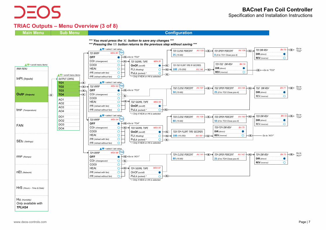
TRIAC Outputs – Menu Overview (3 of 8)
TO1 DIR-REV
DIR (direct)REV (reverse)
PuLs (pulsed) *
AO1
DO2
DO1
AO4
AO3
AO2
DO4
DO3
FLt (floating)
rHt (reheat without fan)
rHt (reheat with fan)
HEAt
rmP (Ramps)
nEt (Network)
HrS (Hours – Time & Date)
Hu (Humidity)
Only available with TFLH24
TO4
TO3
TO2
Output Config
TO1
COOl
COr (changeover)
TO1 Ramp
OFF
SEtc (Settings)
FAN
tmP (Temperature)
OutP (Outputs)
Main Menu
InPt (Inputs)
= scroll menu items
= scroll menu items
= select / set valueTO1 Close Percent
25 (15-80)
TO1 Signal Type
OnOf (on/off)
Go to “TO2"
* = Only if HEAt or rHt is selected
TO1-TO2 Float Time In Seconds
100 (15-250)
TO1 Open Percent
0 (0 to TO1 Close pos-4)
Go to “TO2"
TO2 DIR-REV
DIR (direct)REV (reverse)
PuLs (pulsed) *rHt (reheat without fan)
rHt (reheat with fan)
HEAtCOOl
COr (changeover)
TO2 Ramp
OFF
= select / set value
TO2 Close Percent
50 (15-80)
TO2 Signal Type
OnOf (on/off)
Go to “TO3"
* = Only if HEAt or rHt is selected
TO2 Open Percent
25 (0 to TO2 Close pos-4)
Go to “TO3"
TO3 DIR-REV
DIR (direct)REV (reverse)
PuLs (pulsed) *
FLt (floating)
rHt (reheat without fan)
rHt (reheat with fan)
HEAtCOOl
COr (changeover)
TO3 Ramp
OFF
= select / set valueTO3 Close Percent
80 (15-80)
TO3 Signal Type
OnOf (on/off)
Go to “TO4"
* = Only if HEAt or rHt is selected
TO3-TO4 Float Time Seconds
100 (15-250)
TO3 Open Percent
50 (0 to TO3 Close pos-4)
Go to “TO4"
TO4 DIR-REV
DIR (direct)REV (reverse)
PuLs (pulsed) *rHt (reheat without fan)
rHt (reheat with fan)
HEAtCOOl
COr (changeover)
TO4 Ramp
OFF
= select / set value
TO4 Close Percent
80 (15-80)
TO4 Signal Type
OnOf (on/off)
Go to “AO1"
* = Only if HEAt or rHt is selected
TO4 Open Percent
25 (0 to TO4 Close pos-4)
Go to “AO1"
TO1
TO2
TO3
TO4
Main Menu Sub Menu Configuration
MSV.80
MSV.82
MSV.84
MSV.86
MSV.81
AV.135 AV.136 BV.70
MSV.83
AV.137 AV.138 BV.71
MSV.85
AV.139 AV.140 BV.72
MSV.87
AV.141 AV.142 BV.73
TO1-TO2 DIR-REV
DIR (direct)REV (reverse)
BV.74
Go to “TO3"
TO3-TO4 DIR-REV
DIR (direct)REV (reverse)
BV.75
Go to “AO1"
AV.146
AV.151
*** You must press the button to save any changes *** *** Pressing the button returns to the previous step without saving ***

BACnet Fan Coil Controller Specification and Installation Instructions
www.deos-controls.com Page | 8
Analog Outputs – Menu Overview (4 of 8)
FAN (ECM Fan)
Hu (humidity) *
AO1
DO2
DO1
AO4
AO3
AO2
DO4
DO3
rmP (Ramps)
nEt (Network)
HrS (Hours – Time & Date)
Hu (Humidity)
Only available with FCU CT24H
TO4
TO3
TO2
Output Config
TO1
SEtc (Settings)
FAN
tmP (Temperature)
OutP (Outputs)
Main Menu
InPt (Inputs)
= scroll menu items
= scroll menu items
AO1 DIR-REV
DIR (direct)
REV (reverse)
rHt (reheat without fan)
rHt (reheat with fan)
HEAtCOOl
COr (changeover)
AO1 Ramp
OFF
= select / set value
AO1 Minimum Voltage
0.0 (0-max)
Go to “AO2"
AO1 Maximum Voltage
10.0 (min-10)
Go to “AO2"
AO1
Hu (humidity) *
AO2 DIR-REV
DIR (direct)
REV (reverse)
rHt (reheat without fan)
rHt (reheat with fan)
HEAtCOOl
COr (changeover)
AO2 Ramp
OFF
= select / set value
AO2 Minimum Voltage
0.0 (0-max)
Go to “AO3"
AO2 Maximum Voltage
10.0 (min-10)
Go to “AO3"
AO2
Hu (humidity) *
AO3 DIR-REV
DIR (direct)
REV (reverse)
rHt (reheat without fan)
rHt (reheat with fan)
HEAtCOOl
COr (changeover)
AO3 Ramp
OFF
= select / set value
AO3 Minimum Voltage
0.0 (0-max)
Go to “AO4"
AO3 Maximum Voltage
10.0 (min-10)
Go to “AO4"
AO3
Hu (humidity) *
AO4 DIR-REV
DIR (direct)
REV (reverse)
rHt (reheat without fan)
rHt (reheat with fan)
HEAtCOOl
COr (changeover)
AO4 Ramp
OFF
= select / set value
AO4 Minimum Voltage
0.0 (0-max)
Go to “DO1"
AO4 Maximum Voltage
10.0 (min-10)
Go to “DO1"
AO4
AO4 Minimum Voltage
0.0 (0-max)
AO4 Maximum Voltage
10.0 (min-10)
Go to “DO1"
Main Menu Sub Menu Configuration
MSV.55
MSV.57
MSV.59
MSV.61
AV.100 AV.101 BV.50
AV.103 AV.104 BV.51
AV.106 AV.107 BV.52
AV.109 AV.110 BV.53
AV.109 AV.110
*** You must press the button to save any changes *** *** Pressing the button returns to the previous step without saving ***
* Hu option appears only with a
FCU CT24H thermostat

BACnet Fan Coil Controller Specification and Installation Instructions
www.deos-controls.com Page | 9
Digital Outputs – Menu Overview (5 of 8)
REV (reverse)
Hu (humidity) *
AO1
DO2
DO1
AO4
AO3
AO2
DO4
DO3
rmP (Ramps)
nEt (Network)
HrS (Hours – Time & Date)
Hu (Humidity)
Only available with TFLH24
TO4
TO3
TO2
Output Config
TO1
SEtc (Settings)
FAN
tmP (Temperature)
OutP (Outputs)
Main Menu
InPt (Inputs)
= scroll menu items
= scroll menu items
DO1 DIR-REV
DIR (direct)REV (reverse)
rHt (reheat without fan)
rHt (reheat with fan)
HEAtCOOl
COr (changeover)
DO1 Ramp
OFF
= select / set value
DO1 Close Percent
25 (15-80)
Go to “DO2"
DO1 Open Percent
0 (0 to DO1 Close pos-4)
Go to “DO2"
DO1
Hu (humidity) *
rHt (reheat without fan)
rHt (reheat with fan)
HEAtCOOl
COr (changeover)
DO2 Ramp
OFF
= select / set value
Go to “DO3"
DO2
Hu (humidity) *
rHt (reheat without fan)
rHt (reheat with fan)
HEAtCOOl
COr (changeover)
DO3 Ramp
OFF
= select / set value
Go to “DO4"
DO3
Hu (humidity) *
rHt (reheat without fan)
rHt (reheat with fan)
HEAtCOOl
COr (changeover)
DO4 Ramp
OFF
= select / set value
Go to “tMp"
DO4
do1 contact delay
0 (0-15)
DO2 DIR-REV
DIR (direct)REV (reverse)
DO2 Close Percent
50 (15-80)
DO2 Open Percent
25 (0 to DO2 Close pos-4)
Go to “DO3"do2 contact delay
0 (0-15)
DO3 DIR-REV
DIR (direct)REV (reverse)
DO3 Close Percent
80 (15-80)
DO3 Open Percent
50 (0 to DO3 Close pos-4)
Go to “DO4"do3 contact delay
0 (0-15)
DO4 DIR-REV
DIR (direct)DO4 Close Percent
20 (15-80)
DO4 Open Percent
0 (0 to DO4 Close pos-4)
Go to “tmP"do4 contact delay
0 (0-15)
Main Menu Sub Menu Configuration
MSV.70
MSV.71
MSV.72
MSV.73
AV.115 AV.116 BV.60 AV.117
AV.120 AV.121 BV.61 AV.122
AV.125 AV.126 BV.62 AV.127
AV.130
AV.131 BV.63 AV.132
*** You must press the button to save any changes *** *** Pressing the button returns to the previous step without saving ***
* Hu option appears only with a
TFLH24 thermostat
BACnet Fan Coil Controller Specification and Installation Instructions
www.deos-controls.com Page | 10
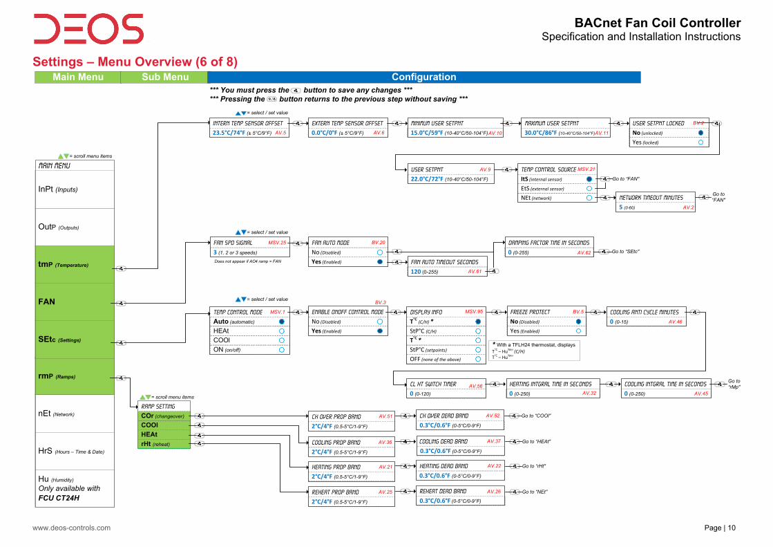
Settings – Menu Overview (6 of 8)
OFF (none of the above)
ON (on/off)
NEt (network)
rmP (Ramps)
nEt (Network)
HrS (Hours – Time & Date)
Hu (Humidity)
Only available with FCU CT24H
SEtc (Settings)
FAN
tmP (Temperature)
OutP (Outputs)
Main Menu
InPt (Inputs)
= scroll menu items
Main Menu
= select / set value
Intern Temp Sensor Offset
23.5°C/74°F (± 5°C/9°F)
Extern Temp Sensor Offset
0.0°C/0°F (± 5°C/9°F)
Minimum User Setpnt
15.0°C/59°F (10-40°C/50-104°F)
Maximum User Setpnt
30.0°C/86°F (10-40°C/50-104°F)
User Setpnt Locked
No (unlocked)
Yes (locked)
User Setpnt
22.0°C/72°F (10-40°C/50-104°F)
Temp Control Source
ItS (internal sensor)
EtS (external sensor)
Go to “FAN"
Go to “FAN"Network timeout Minutes
5 (0-60)
= select / set value
damping factor time in seconds
0 (0-255)
Fan Auto Mode
No (Disabled)
Yes (Enabled)
Fan Spd Signal
3 (1, 2 or 3 speeds)
Fan Auto Timeout Seconds
120 (0-255)
COOl
Temp Control Mode
Auto (automatic)
HEAt
= select / set value
Go to “SEtc"
Enable onoff Control Mode
No (Disabled)
Yes (Enabled)
StP°C (setpoints)
T°C*
Display Info
T°C (C/H) *StP°C (C/H)
Freeze Protect
No (Disabled)
Yes (Enabled)
Cooling anti cycle minutes
0 (0-15)
cl ht switch timer
0 (0-120)
Heating Intgral time in Seconds
0 (0-250)
Cooling Intgral time in Seconds
0 (0-250)
Go to “rMp"
CH Over Prop Band
2°C/4°F (0.5-5°C/1-9°F)
CH Over Dead Band
0.3°C/0.6°F (0-5°C/0-9°F)
rHt (reheat)
HEAt
COOl
Ramp Setting
COr (changeover)
= scroll menu items
Cooling Prop Band
2°C/4°F (0.5-5°C/1-9°F)
Cooling Dead Band
0.3°C/0.6°F (0-5°C/0-9°F)
Heating Prop Band
2°C/4°F (0.5-5°C/1-9°F)
Heating Dead Band
0.3°C/0.6°F (0-5°C/0-9°F)
Reheat Prop Band
2°C/4°F (0.5-5°C/1-9°F)
Reheat Dead Band
0.3°C/0.6°F (0-5°C/0-9°F)
Go to “COOl"
Go to “HEAt"
Go to “rHt"
Go to “NEt"
Sub Menu Configuration
AV.5 AV.6 AV.10 AV.11
BV.2
AV.9 MSV.21
AV.2
MSV.25 BV.20
MSV.1
BV.3
MSV.95 BV.5
AV.46
AV.56
AV.32 AV.45
AV.51 AV.52
AV.36 AV.37
AV.21 AV.22
AV.25 AV.26
Does not appear if AO4 ramp = FAN
AV.61
AV.62
*** You must press the button to save any changes *** *** Pressing the button returns to the previous step without saving ***
* With a TFLH24 thermostat, displaysT°C – Hu%RH (C/H)T°C – Hu%RH

BACnet Fan Coil Controller Specification and Installation Instructions
www.deos-controls.com Page | 11
Network and Calendar – Menu Overview (7 of 8)
in (in progress)
CPYc (copy config)
bAC
mOd
Network Config
tYPe (Type)
= scroll menu items
rmP (Ramps)
nEt (Network)
HrS (Hours – Time & Date)
Hu (Humidity)
Only available with FCU CT24H
SEtc (Settings)
FAN
tmP (Temperature)
OutP (Outputs)
Main Menu
InPt (Inputs)
= scroll menu items
Main Menu Sub Menu Configuration
Network Choice
bAC (BACnet)
mOd (Modbus)
= select / set value
Modbus Auto Baud Rate
No (Manual)
Yes (Automatic)
= select / set value
bacnet Auto Baud Rate
No (Manual)
Yes (Automatic)
= select / set value
= select / set value
Start Address
0 (0-254)
Go to “bAC"
Go to “mOd"
If type = bAC, menu contains “tYpe”, “bAC” and “CPYc”
If type = mOd, menu contains “tYpe and “mOd”
Modbus Baud Rate
57.6k (9.6k, 19.2k, 38.4, 57.6k)
Bacnet Baud Rate
76.8k (9.6k, 19.2k, 38.4, 76.8k)
MSTP MAC Address
0 (0-254)
Modifiable only if Auto Baud Rate
set to “No”.
Modifiable only if Auto Baud Rate
set to “No”.
Modifiable only if all DS2 DIP
switches are set to OFF.
0153000
0 (device instance)
Go to “CPYc"MSTP MAX Master
127 (1-127)
OP1s (odd parity, 1 stop bit)
Modbus Comport Config
NP2s (no parity, 2 stop bits)
EP1s (even parity, 1 stop bit)
Modbus Address
1 (1-246)
Modifiable only if all DS2 DIP
switches are set to OFF.
Go to “HrS"
End Address
0 (0-254, start address+63)
Confirm Copy Config
No (cancel)
Yes (confirm)
Copy Config
Go to “HrS"
Copy Config Succeed
(done)
Go to “HrS"
= select / set value
Hours
12 (0-23 or 1-12 am/pm)
Minutes
00 (00-59)
Year
15 (15-99)
Set Time Display format
24 (24-hour format)
12 (AM/PM format)
Month
1 (1-12)
Day
1 (1-31)
Go to “InPt" if using a TFLH24, go to “Hu”
10001001
AV.165 AV.166 BV.90
Local Time
AV.167
Local Time Local Date
Local Date Local Date
*** You must press the button to save any changes *** *** Pressing the button returns to the previous step without saving ***
BACnet Fan Coil Controller Specification and Installation Instructions
www.deos-controls.com Page | 12
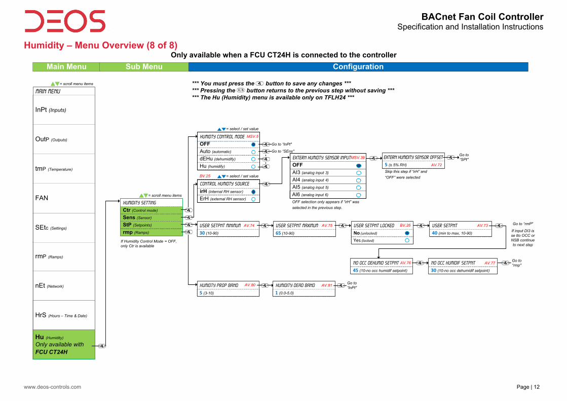
Humidity – Menu Overview (8 of 8) Only available when a FCU CT24H is connected to the controller
AI6 (analog input 6)irH (internal RH sensor)
Hu (humidify)
dEHu (dehumidify)
Auto (automatic)
OFF
rmP (Ramps)
nEt (Network)
HrS (Hours – Time & Date)
Hu (Humidity)
Only available with FCU CT24H
SEtc (Settings)
FAN
tmP (Temperature)
OutP (Outputs)
Main Menu
InPt (Inputs)
= scroll menu items
Main Menu Sub Menu Configuration
rmp (Ramps)
StP (Setpoints)
Sens (Sensor)
Humidity Setting
Ctr (Control mode)
= scroll menu items
Humidty control Mode
= select / set value
Go to “InPt"
Go to “SEns"
ErH (external RH sensor)
Control Humidty Source
= select / set value
AI5 (analog input 5)
AI4 (analog input 4)
AI3 (analog input 3)
Extern Humidty Sensor Input
OFF
OFF selection only appears if “irH” was
selected in the previous step.
Extern humidity Sensor Offset
5 (± 5% RH)
Skip this step if “irH” and
“OFF” were selected
Go to “SPt"
User Setpnt Minimum
30 (10-90)
User Setpnt Maximum
65 (10-90)
User Setpnt Locked
No (unlocked)
Yes (locked)
User Setpnt
40 (min to max, 10-90)
Humidty Prop Band
5 (3-10)
Humidity Dead Band
1 (0.0-5.0)
Go to “InPt"
No OCC Dehumid Setpnt
45 (10-no occ humidif setpoint)
No OCC Humidif Setpnt
30 (10-no occ dehumidif setpoint)
Go to “rmp"
Go to “rmP"
If input DI3 is se tto OCC or NSB continue to next step
If Humidity Control Mode = OFF, only Ctr is available
MSV.5
BV.25
AV.74
MSV.39
AV.75 BV.26
AV.76
AV.73
AV.77
AV.80 AV.81
AV.72
*** You must press the button to save any changes *** *** Pressing the button returns to the previous step without saving ****** The Hu (Humidity) menu is available only on TFLH24 ***
BACnet Fan Coil ControllerSpecification and Installation Instructions
www.deos-controls.com Page | 13
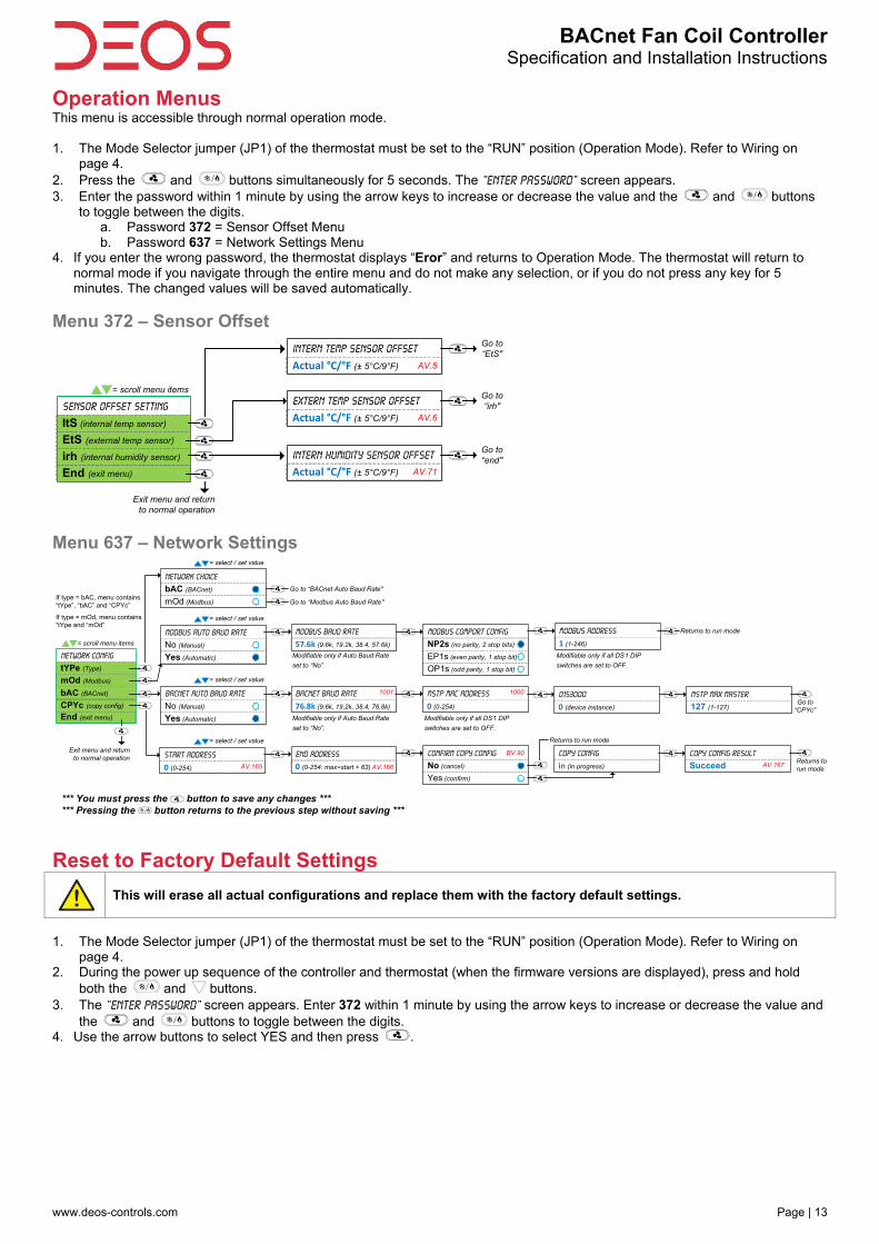
Operation Menus This menu is accessible through normal operation mode. 1. The Mode Selector jumper (JP1) of the thermostat must be set to the “RUN” position (Operation Mode). Refer to Wiring on
page 4. 2. Press the and buttons simultaneously for 5 seconds. The “Enter Password” screen appears. 3. Enter the password within 1 minute by using the arrow keys to increase or decrease the value and the and buttons
to toggle between the digits. a. Password 372 = Sensor Offset Menu b. Password 637 = Network Settings Menu
4. If you enter the wrong password, the thermostat displays “Eror” and returns to Operation Mode. The thermostat will return to normal mode if you navigate through the entire menu and do not make any selection, or if you do not press any key for 5 minutes. The changed values will be saved automatically.
Menu 372 – Sensor Offset
Menu 637 – Network Settings
Reset to Factory Default Settings
This will erase all actual configurations and replace them with the factory default settings.
1. The Mode Selector jumper (JP1) of the thermostat must be set to the “RUN” position (Operation Mode). Refer to Wiring on
page 4. 2. During the power up sequence of the controller and thermostat (when the firmware versions are displayed), press and hold
both the and buttons. 3. The “Enter Password” screen appears. Enter 372 within 1 minute by using the arrow keys to increase or decrease the value and
the and buttons to toggle between the digits. 4. Use the arrow buttons to select YES and then press .
End (exit menu)
irh (internal humidity sensor)
EtS (external temp sensor)
Sensor Offset setting
ItS (internal temp sensor)
= scroll menu items
Exit menu and return to normal operation
Intern Temp Sensor Offset
Actual °C/°F (± 5°C/9°F) AV.5
Extern Temp Sensor Offset
Actual °C/°F (± 5°C/9°F) AV.6
Intern Humidity Sensor Offset
Actual °C/°F (± 5°C/9°F) AV.71
Go to “EtS"
Go to “irh"
Go to “end"
End (exit menu)
CPYc (copy config)
bAC (BACnet)
mOd (Modbus)
Network Config
tYPe (Type)
= scroll menu items
Network Choice
bAC (BACnet)
mOd (Modbus)
= select / set value
Modbus Auto Baud Rate
No (Manual)
Yes (Automatic)
= select / set value
BACnet Auto Baud Rate
No (Manual)
Yes (Automatic)
= select / set value
= select / set value
Start Address
0 (0-254)
If type = bAC, menu contains “tYpe”, “bAC” and “CPYc”
If type = mOd, menu contains “tYpe and “mOd”
Modbus Baud Rate
57.6k (9.6k, 19.2k, 38.4, 57.6k)
Bacnet Baud Rate
76.8k (9.6k, 19.2k, 38.4, 76.8k)
MSTP MAC Address
0 (0-254)
Modifiable only if Auto Baud Rate
set to “No”.
Modifiable only if Auto Baud Rate
set to “No”.
Modifiable only if all DS1 DIP
switches are set to OFF.
0153000
0 (device instance)Go to
“CPYc"
MSTP MAX Master
127 (1-127)
OP1s (odd parity, 1 stop bit)
Modbus Comport Config
NP2s (no parity, 2 stop bits)
EP1s (even parity, 1 stop bit)
Modbus Address
1 (1-246)
Modifiable only if all DS1 DIP
switches are set to OFF.
Returns to run mode
End Address
0 (0-254: max=start + 63)
Confirm Copy Config
No (cancel)
Yes (confirm)
Copy Config
in (in progress)
Returns to run mode
Copy Config Result
Succeed
1001
AV.166AV.165
1000
BV.90
AV.167
Exit menu and return to normal operation
Go to “BACnet Auto Baud Rate"
Go to “Modbus Auto Baud Rate"
Returns to run mode
*** You must press the button to save any changes *** *** Pressing the button returns to the previous step without saving ***
BACnet Fan Coil ControllerSpecification and Installation Instructions
www.deos-controls.com Page | 14
Operation Mode The Mode Selector Jumper of the thermostat must be set to the “RUN” position (Operation Mode). Refer to Wiring on page 4.
Power Up Upon power up, the LCD illuminates and all segments appear for 2 sec. The thermostat then displays its current version of the thermostat for 2 seconds followed by the current version of the controller for 2 seconds.
LCD Backlight Pressing any key on the thermostat illuminates the LCD for 4 seconds.
Temperature The thermostat displays the temperature reading. If the sensor is disconnected or short circuited, the unit displays the sensor's limits. To toggle the temperature scale between ºC and ºF, press both the and keys for 3 seconds.
Temperature and Humidity (TFLH24 thermostats only) The thermostat displays the temperature reading for 8 seconds and then displays the humidity reading for 2 seconds. If the sensor is disconnected or short circuited, the unit displays the sensor's limits. To toggle the temperature scale between ºC and ºF, press both the and keys for 3 seconds.
Temperature Setpoint Display and Adjustment To display the setpoint, press the or key twice. The setpoint appears for 5 seconds. To adjust the setpoint, press the arrow keys while the temperature is displayed. If the setpoint adjustment has been locked, the lock symbol appears.
Humidity Setpoint Display and Adjustment (TFLH24 thermostats only) To access the Humidity setpoint, press the button for 5 seconds. The humidity setpoint will be displayed for 5 seconds. To adjust the setpoint, press the and keys while the setpoint is displayed. If the humidity sensor is disconnected or short circuited, the unit displays the sensor's limits. The unit will return to normal mode if you do not press any key for 3 seconds. The changed values will be saved automatically.
Control Mode To access the Control Mode, press the key. The Control Mode appears for 5 seconds. Press the key to scroll through the following control modes. These options can vary depending on the options selected. Auto (Automatic Cooling or Heating) Cooling only (on, with cooling symbol) Heating only (on, with heating symbol) OFF (if it is not disabled in Programming Mode)
Fan Speed Selection Mode To access the Fan Speed selection mode, press the key. The mode appears for 5 seconds. These options can vary depending on the fan speed signal and auto mode settings. If the user speed selection is locked, a symbol and “setpnt locked” message appear. If in No Occupancy mode, the button now serves as the override button. Automatic speed. Available only if enabled in program mode. Low speed Medium speed High speed Off. Off is not selectable by the user, it appears only if the "Control Mode" is "Off" and it indicates that the user can not change
the speed of the fan.
Night Set Back (NSB) This function is only available if you’ve set DI3 to nSb (Night set back contact) If the DI3 contact is triggered, the thermostat enters NSB Mode (the symbol appears) and uses the NSB setpoints defined in program mode. Press any key to override NSB for the delay defined in program mode (default: 120 minutes). The symbol flashes to indicate that the NSB mode is overridden (during this time the standard set points are used). If the NSB Mode was set to OFF, all outputs will be off for the duration of the period and cannot be overridden.

BACnet Fan Coil ControllerSpecification and Installation Instructions
www.deos-controls.com Page | 15
Occupancy Mode This function is only available if you’ve set DI3 to Occ (occupancy mode). If the DI3 contact is triggered, the thermostat enters Occupancy Mode (the symbol appears) and uses the NoOcc setpoints defined in program mode. If not locked, no occupancy mode can be overridden for a period by pressing the button. Each time you press the button, 15 minutes are added to the override (up to a maximum defined in program mode. Press the fan button until “0” is displayed to disable the override. The icon will flash and the remaining override time will be displayed in minutes.
Set Time and Date 1. Ensure that JP1 on the thermostat is set to run. 2. Press and hold the button for 5 seconds 3. Use the arrow keys to set the desired value. Press the button to save and got to the next step. Press the button to
go to the previous step without saving.
= select / set value
Hours
12 (0-23 or 1-12 am/pm)
Minutes
00 (00-59)
Year
15 (15-99)
Set Time Display format
24 (24-hour format)
12 (AM/PM format)
Month
1 (1-12)
Day
1 (1-31)
Exits and returns to RUN mode
Local Time Local DateLocal Time
Local DateLocal Date

BACnet Fan Coil ControllerSpecification and Installation Instructions
Notes
Recycling at end of life: please return this product to your local distributor for recycling.
4010 1st Avenue, Burnaby BC V5C 3W4, Canada
www.deos-controls.com
Tel.: +1 604.239.7204