Embed Size (px)
Citation preview

Balance of Forces in Simulated Bilayers†
J. SteckiDepartment III, Institute of Physical Chemistry, Polish Academy of Sciences, ul.Kasprzaka 44/52, 01-224 Warszawa, Poland
ReceiVed: NoVember 9, 2007; In Final Form: December 15, 2007
Two kinds of simulated bilayers are described, and the results are reported for lateral tension and for partialcontributions of intermolecular forces to it. Data for the widest possible range of areas per surfactant head,from tunnel formation through tensionless state, transition to floppy bilayer, and its disintegration, are reportedand discussed. The significance of the tensionless state is discussed.
I. Introduction: Two-Dimensional Sheets in ThreeDimensions
Great interest in the properties of membranes and bilayers isreflected in the very large volume of work reporting simulationsof a variety of models and simulation methods. However,simulations including a range of areas are relatively rare, andthose including the widest possible range of areas are rarerstill.1-6 Most papers concentrate on the “tensionless state” forwhich the lateral tension vanishes.
The latter is the direct counterpart of the surface (interfacial)tension between two liquids, and in fact it is computed accordingto the same Kirkwood-Buff formula.7
At this stage we must mention that the physicochemicalproperties of a sheet of surfactant molecules, forming a bilayer,are positively exotic. Compare with a planar interface between,e.g., a liquid and its vapor or two immiscible liquids. Then thesurface tensionγ is defined by
whereF is the free energy,A is the area,V is the volume andthe constancy of particle numbers, and the temperatureT isunderstood. Butγ itself is independent of the area; it is a materialproperty, a function of state. In a shocking contrast to that, thelateral tension of a bilayer (again defined after eq 1.1) is area-dependent; moreover, in the same system as to composition,density, and temperature,γ(A) can be positive or negative. Itszero defines the “tensionless state”, which is of particular interestand some physical significance.
Other properties, such as internal energyU or correlationfunctions including the structure factorS(q), also display thearea dependence if a sufficiently wide interval of areas isinvestigated.
The peculiar shape of thebilayer isotherm, i.e., of the functionand plot ofγ(A), as shown and discussed in Section II, raisesthe question as to how it originates. A partial answer to that isprovided by the split ofγ into its components.
Not all simulations are “atomistic”, i.e., not all simulationsconstruct the intermolecular total energyE({r}) from modelintermolecular potentials depending only on the spatial coor-dinates of the constituent particles (atoms or molecules), theenergy of which is then used in a Monte Carlo or molecular
dynamics simulation scheme. One of the advantages of anatomistic simulation is the possibility of examining the role ofthe constituent components such as surfactant heads, solventmolecules, and surfactant tails. This is put to use in this paper,in which we report the split of lateral tension.
Our results are reported for two kinds of simulated bilayers;these are defined in Section II.
In Section III we show the split of lateral tension intocomponents, and we discuss the physical meaning of the“tensionless state”.
In Section IV we return to the discussion of bilayer propertiesand deeper distinctions between interfaces and membranes orbilayers. The discussion introduces the concept of constraint.
It also appears to be necessary to point out that a veryimportant category of objects, called “vesicles”, is entirelyoutside the realm of simulated bilayers. Merging “membranesand vesicles” in one sentence greatly oversimplifies matters,because vesicles, like spherical micelles floating in a solvent,enclose a finite volume. The bilayers do not.
The “widest possible range of areas” of a simulated bilayer,mentioned above, refers to the limits of existence of a stablebilayer. When the imposed area is extended too much, thebilayer recedes, creating a spherical hole or rather a tunnel filledwith solvent joining the two sides of the solvent volume. Whencompressed, the bilayer flips into a “floppy” state (see SectionIII), which, if compressed further, disintegrates into structurelessobject(s) that can no longer be called a bilayer.
Section II. Two Kinds of Bilayers
A planar bilayer is formed by amphiphilic surfactant mol-ecules, each made of a hydrophilic polar “head” and hydro-phobic nonpolar hydrocarbon chains as “tails”. The tails formthe center of the bilayer and the two outer layers of headsseparate the tails from the polar solvent (water). Therefore, thecohesive energy density (CED)8 is high (solvent), high (firstlayer of heads), low (tails), low (second layer of tails), high(second layer of heads), high (solvent on the other side of thebilayer).
The same forces and the same preferences operate in theformation of micelles of various shapes. Normally the solventis polar, of high CED, and most commonly water, and themicelles shield their hydrocarbon tails by an outer layer of headsin contact with water. However, there exist rare examples ofreVersemicelles, which are formed by amphiphilic molecules
† Originally submitted for the “Keith E. Gubbins Festschrift”, publishedas the November 1, 2007, issue ofJ. Phys. Chem. C(Vol. 111, No. 43).
(∂F/∂A)V ) γ (1.1)
4246 J. Phys. Chem. B2008,112,4246-4252
10.1021/jp710744t CCC: $40.75 © 2008 American Chemical SocietyPublished on Web 03/14/2008

in a nonpolar solvent of low CED. In reverse micelles, the(hydrocarbon) tails form the outward shell, and the (polar) headsare in the center of the micelle. By analogy with these, I have2,4
constructed in simulationsreVerse bilayersthat are formed ina nonpolar solvent of low CED. Upon crossing the reversebilayer along thez-direction perpendicular to thex-y plane ofthe bilayer, the sequence is now solvent, tails, heads, heads,tails, solvent, or, in terms of CED, low, low, high, high, low,low.
These cases can be and have been modeled with the use ofLennard-Jones (LJ) (6-12) potential with a minimum of threekinds of particles: s (solvent), h (head), and t (tail). With sixenergies, six collision diameters, and six cutoff radii, varioussimplifications have been used in bilayer simulations with theLJ potentials.1-5,9-13
In our work, the solvent was made of structureless sphericalparticles; freely jointed chains of such particles of the same sizehave modeled the surfactant molecules making up the bilayer.
We found certain regularities in the stability of the modelbilayers. We found that the chain lengths of the tails can beshortened even down to unity, and the molecule then becomesa dimer (“h-t”) made of two particles. We also found that it isworthwhile to keep the presence of the solvent; in somesimulations, very unusual, in fact unphysical, intermolecularforces were required in order to ensure the existence (insimulation) of stable bilayers14 made of trimers. ThereVersebilayers made of trimers were successfully simulated without asolvent,15 although it appears this was not followed with furtherwork. We also found that longer chains stabilize the bilayer; ofthe tail lengthsl ) 1, 4, 8, the dimers were difficult to stabilizewithout an extra repulsion (replacing the hydrophobic effect)from the solvent, whereas, for longer chains, this extra repulsionwas not necessary for stability. Chains withl ) 8 producedstable bilayers with great ease.
The modeling of solvent as made of spherical structurelessparticles interacting with a central potential creates a certainconceptual difficulty because of the hydrophobic effect. It hasbeen partially resolved by an introduction9 of an additionalrepulsive force between the solvent and the tails, e.g., of theform c/rn with c > 0 andn ) 10 or more.9-13 A temperaturedependence would also be needed, to take into account theentropic effects of the hydrophobicity.
In the case of a reverse bilayer, the reasons for its formationare mostly energetic: a pair of heads (now inside the bilayer)attract each other more strongly than any other pair, and thereis no hydrophobic effect since the solvent is nonpolar with aweak CED.
Section III. The Lateral Tension and its Components
A bilayer, originally planar, lies in thex-y plane in the middleof a simulation box, which is a parallelepiped of volumeV )Lx × Ly × Lz; its area isA ) LxLy. It is made ofNm moleculeswhich containNm heads, originallyNm/2 in each of the twomonolayers, so that the “area per head”a ) A/(Nm/2). Thebilayer is surrounded “from above” and “from below” byNs
molecules of the solvent. The overall density isF ) N/V withN ) Ns + (l + 1)Nm. The lateral tension is defined7 as theresponse to the process of increasing the area at constant volume.With Lx f Lx + δLx, Ly f Ly + δLy, Lz f Lz + δLz, theconstraint of constant volume requiresδLx/Lx + δLy/Ly + δLz/Lz ) 0, and the Kirkwood-Buff equation follows
with the known definitions
valid for a rectangular box. The average is a canonical averageat given temperatureT, all N’s, A, andV. In the simulation, foreach state point ofT, V, Nm, Ns, andA, we obtain one value ofγ(A). In our work,Lx ) Ly; after changingLx to any new value,we calculate the new value ofLz needed to keep the volumeV) LxLxLz at exactly the same value.
Each timeγ is computed, it is a sum of binary terms, andthese are grouped into partial sums so as to produce the split
Here the index ss refers to the solvent-solvent part, the indicessb and bs refer to the solvent-bilayer part, and bb refers to thebilayer-bilayer part. There is no approximation involved.
Figure 1 shows an example of a bilayer made of chainmolecules of tail lengthl ) 4 plus one more particle as thehead, immersed in a solvent at high liquid-like density. EachγRâ is plotted against the area per heada; the lines joining thedata points are there to guide the eye, only. The contribution ofsolvent-solvent pairs is about 0.2-0.3 and almost constant,i.e., independent ofa. All pairs made of solvent particle andany particle of any bilayer molecule make up the sb or bscontribution; it is also positive, varying smoothly witha, andtaking values between 0.5 and 1.05. The bb contribution showsthe characteristic break into two curves, nearly linear witha,but one with positive slope and the other with a negative one.This pattern is transferred to the sum, eq 3.3, totalγ(a).
Figure 2 shows the effect of size for the same chain-lengthl ) 4. The solvent-solvent contributionγss(a) is practicallyindependent of size, as is (nearly so) the solvent-bilayer part.
γA ) Lz(2pzz- pxx - pyy)/2 (3.1)
Figure 1. The general pattern of splits of lateral tensionγ accordingto eq 3.3 is shown as plots against the area-per-heada; here, for anintermediate size of simulated bilayer withNm ) 1800 molecules withtails l ) 4 segments long, with all collision diametersσ and all energiesε equal, atT ) 1, Ns + (l + 1)Nm ) 49000, liquid densityF ) 0.89204.The ss contribution is marked with squares, the sb contribution ismarked with stars, the bb contribution is marked with crosses, and thesum is marked with black circles. All data are quoted everywhere inLJ units reduced by the energy depthε and collision diameterσ. Thelines are there to guide the eye.
pRR ) ⟨∑j
rjR ∂E
∂rjR⟩ (3.2)
γ ) γss+ γsb + γbs + γbb (3.3)
Balance of Forces in Simulated Bilayers J. Phys. Chem. B, Vol. 112, No. 14, 20084247

The bb part and, consequently, the totalγ display the breakinto two regions; the floppy part is strongly affected by sizeand the extended region is negligibly so. The bigger size showsflatter γ(a), still negative, but closer to zero. The lowest valuesof γ(a), which may be taken as the border between the floppyregion and the extended region, are negative, but a lower valuecorresponds to smaller size.
These remarkable patterns are repeated for chain lengthl )8, with breaks much more pronounced. Figure 3 showsγRâ(a)for two sizes; the intermediate size is omitted, just as in Figure2, in order to make the plot clearer. Again, the ss part is constant
and size-independent, the sb part is nearly so, and the totalγalong with the sb part shows these remarkable features: breaksand abrupt changes of slope. For largea, the slope is positive,and the size-dependence is negligible. The transition to thefloppy region occurs neara ) 1.8 for the smaller system, andthe slope dγ/da changes sign; the break is very pronounced.The transition is shifted toa ) 1.9 in the bigger system, andthe break is more pronounced in the bb part than in the totalγ.Most characteristically in the bigger system,γ(a) is flat andnear zero (although still always negative) in the floppy region.
Figure 2. The split of lateral tensionγ plotted against the area-per-heada for two sizes (SM) and (B) of a simulated bilayer, made ofNm ) 450(SM) andNm ) 3973 (B) molecules with tailsl ) 4 segments long, with all collision diametersσ and all energiesε equal, atT ) 1, Ns + (l + 1)Nm
) 12250 (SM) and 105134 (B), liquid-like densityF ) 0.89204. With the notation of eq 3.3, the contribution ss is shown with triangles (SM) andsquares (B) near 0.2-0.3; sb is shown with plus signs (SM) and stars (B) near 0.5-0.7; bb is shown with open circles (SM) and crosses (B) withnegative slope for smalla and positive slope for largea. The sum after eq 3.3,γ, is shown with thick lines, black squares (SM), and black circles(B). See text and the caption to Figure 1. Compare with Figure 3.
Figure 3. The split of lateral tensionγ plotted against the area-per-heada for two sizes (SM) and (B) of a simulated bilayer, made ofNm ) 450(SM) andNm ) 3973 (B) molecules with tailsl ) 8 segments long, with all collision diametersσ and all energiesε equal, atT ) 1, N ) Ns + (l+ 1)Nm ) 14050 (SM) and 121026 (B), and densityF ) 0.89204. With the notation of eq 3.3, the contribution ss is shown with triangles (SM) andsquares (big) near 0.2-0.3; sb is shown with plus signs (SM) and stars (big) near 0.5-1.1; bb is shown with open circles (SM) and crosses (B).Note the negative slope for smalla and positive slope for largea. The sum after eq 3.3 is shown with thick lines, black squares (SM), and blackcircles (B) (see text). Compare with Figure 2 and note the unique breaks inγsb, and the almost constant slope in the region of floppy bilayer,translated into zero slope in totalγ.
4248 J. Phys. Chem. B, Vol. 112, No. 14, 2008 Stecki

The tensionless point appears to lie on the right-hand side (rhs)curve (extended bilayer region) in this case.
All bilayer isotherms, i.e., all plots ofγ(a) we haveobtained,1-4 show the same pattern of two curves joined at somenegative value of the lateral tensionγ. We interpret the regionof lowera as the region of thefloppy stateof the bilayer, whichescapes into the third dimension, buckles, and takes a fuzzyand irregular form. A gently fluctuating planar bilayer is foundin the other region at highera’s. Generally, the region ofextended bilayer includes all states with positiveγ. The crossingof the isotherm with thea-axis marks thetensionless state. Inthe plots of Figures 1-3, the region of the extended bilayerhas a large positive slope ofγ(a). Such positive slopes havebeen found independently5,6 and also previously.9-13 The entirerange including the floppy region is found only in a fewreferences.2-6 The corresponding split of the lateral tension isfound in this paper only.
The status of the tensionless state appears now, in a new light,as an accidental event resulting from the algebraic sum ofpositive and negative contributions after eq 3.3. The partialcontributions suggest that the break point dividing the twobranches ofγ(a) (or γbb(a)) is a truly characteristic point thatought to have a physical significance, rather thanγ(a0) ) 0.
The shortest possible tail of one particle is present in a dimer.We have attempted and partially succeeded1 in simulatingbilayers made of dimers, but these appeared to be onlyimperfectly stabilized by strong head-head and head-solventinteractions or/and the extra repulsion introduced artificially tomimic the hydrophobic effect, as invented earlier.9 Possibly atother densities and temperatures, the simulations would havebeen more encouraging. We do not show these results. Asmentioned in Section II, we turned to the new case ofreVersebilayers formed in a weakly interacting solvent and succeededin producing (in simulation) stable reverse bilayers of am-phiphilic dimers.2,4 Figures 4 and 5 show a selection of severalcharacteristic cases, each for two sizes. These cases are (a) extrarepulsion added, (b) no extra repulsion, and (c) no extrarepulsion and longer range of attractive forces. In cases a and
b, the cutoff was the generally usedr ) 2.5; in case c, it wasr ) 3.2. For clarity, we split the data into two figures: Figure4 showsγ total only, for all five systems, whereas Figure 5shows the components ss, sb, and bb. All curves for all fivesystems in Figure 4 show a pattern similar toγ(a) in Figure 3(for l ) 8). This characteristic pattern is an almost linear risewith a for largera, and an almost constant negativeγ for smalla. Such a description fits bigger systems better. The biggestsystem of an area (about 100× 100) of reverse dimers (case a)is shown in ref 4. As can be seen from Figure 4, the plot againstrongly suggests a transition between two forms of the bilayerand certainly the existence of two regions.1-5 In the floppyregion,γ < 0, and the closer to zeroγ becomes, the bigger thesystem. Figure 5 shows the components ofγ but withoutγ itself.The pattern is similar to those shown in Figures 1-3, exceptthat the ss contribution toγ is now negative (between-0.6and-0.2), and the sb contribution is much larger (between 2and 3.6). The bb contribution is, for all sizes, practically linearin a with, again, negative slope and negative value in the regionof “floppy” state. The transition appears to be softer than thatfor chain molecules, especially those with longer tails wherethe breaks were sharp (see Figure 3) in small systems.
The status of the tensionless state appears to be relegated tothe category of accidental coincidences. An analogy may bedrawn between the equation of state of liquid in equilibriumand its saturated vapor; certainlyP ) 1 is a particular point onthe vapor pressure curve, but it has no particular physicalmeaning, in contrast with, e.g., the triple point. The only physicalconsequence of zero in lateral tension is the special form of thestructure factor.1-5,10 However, even this has been questionedrecently.4,12 In a detailed investigation of the structure factorS(q) of a simulated bilayer, which should, for smallq,asymptotically vary as 1/S∼ kq4 + gq2, wherek is the rigidityconstant andg is the surface tension, we foundg g γsystematically.4 The explanation advanced elsewhere12 is thatγδA is not the correct work of deforming a bilayer that wasinitially planar, butgδAtrue is. HereAtrue is the true area of theinterface or bilayer, obtained by following its surface, whereas
Figure 4. Total lateral tensionγ of reverse bilayers made of dimer molecules plotted against area-per-heada for biggest (B) or smallest (SM) size,and three cases: (a) extra repulsion added and head-head attraction enhanced (H-H); (b) only H-H; (c) the cutoff of attraction is a long-rangerc ) 3.2, notrc ) 2.5; otherwise, a applies. The other parameters areT ) 1.9,F ) 0.89024,Nm ) 2238 dimers,N ) Ns + 2Nm ) 40000 (SM) andNm ) 5760 dimers,N ) Ns + 2Nm ) 160000 (B). These had areas near 36× 36 and near 55× 55. The points are as follows: open squares-Ba; plus signs- SMa; black squares- Bb; crosses- SMb; stars- SMc. The lines are there to guide the eye only. The deviation of data-pointat a ∼ 1.13 (black square) is due to the tunnel (hole). See Figure 5 and text.
Balance of Forces in Simulated Bilayers J. Phys. Chem. B, Vol. 112, No. 14, 20084249

A ≡ LxLy is the projected area. Since S(q) measures thespontaneous fluctuations,gq2 is correct, andγq2 is not. On theother hand, when measuring the response of the system to animposed change in the projected area,γδA is the correct freeenergy increment. The increase in the projected area is underthe control of the experimentalist; the change of the true areainduced by the twists and bends of the bilayer is not. By takingthese arguments into account, the correct definition of thetensionless state was assumed12 to beg ) 0, and interpolationprocedures were used12 to determine the new correct tensionlessstate. Whether the details of the advanced explanation12 arecorrect or not, it is obvious thatg parametrizes the spectrumS(q) of spontaneous shape fluctuations. The difference betweeng andγ was also discussed elsewhere.6,13,15The zero ofγ(a) isunambiguous in small systems; in large system of reversebilayers4 it falls within the narrow region of fastest changein slope, signaling the transition of the bilayer to the floppystate. Then the precision of its determination is doubtful.Some of this ambiguity is seen in Figure 4 and in the figures ofref 4.
Section IV. Discussion
We have noted in the Introduction that, to a physical chemistfamiliar with the interfaces, some properties of a bilayer aretruly exotic. Let us list these properties: (1) the derivative givenby eq 1.1 depends on the specific area; (2) it can be negative;(3) extension of the area leads to a hole or tunnel as the bilayerresists further extension; (4) there is distinction between theactual area and the projected area, but the bilayer keeps its truearea nearly constant; (5) as there are two areas, there are twointerfacial tensions.
This is definitely not what we learn from classical textbookson thermodynamics.
Feature 1 has been seen in all simulations, including theseover a wide range of (projected) areas.1-6,9-15 Feature 2 hasalso been seen.2-6,11-13,15Feature 3 has not only been seen,2,4,15
but also investigated.15 Distinction 4 has been the subject ofpapers5,13 specifically devoted to it. Finally, the existence of
an(other) surface tension(s), besides the lateral tension, has beenrepeatedly surmised;5,6,11,13equations have even been derived.14
The explanation of such specific behavior ultimately lies withintermolecular forces and steric effects that any future theorywill have to take into account. The bilayers are made ofamphiphilicmolecules, each containing a hydrophilic part anda hydrophobic part (or, more generally, “solvophilic” and“solvophobic”). These molecules use their very special setupof intermolecular forces to create a stable sheet of constant mass(and approximately constant area). This creates a new situationwith a constraint of given total area almost conserved whenthe projected area is varied by varying the simulation box.
The constraint of constant mass (or anything related to it) isentirely absent in fluctuating interfaces. The molecular mech-anism of fluctuations of shape of, e.g., a liquid-vapor interface,involves diffusion from either phase; a local protrusion orexcursion of the interface takes place not only by deformingthe existing surface but also by absorbing or releasing moleculesfrom/to either phase.
The surface of a perfect crystal in equilibrium with its vaporis a good example; all shape fluctuations are due to evaporationor condensation.
Such processes clearly take part in shape fluctuations of aliquid surface as well.
Hence an interface is a system open with respect to particlenumber. It is not so with the bilayer. Not only is the solventvirtually absent from the bilayer, but also the surfactantmolecules, making the bilayer never leave it. In principle, thesurfactant must be present in the solvent, but the bilayer changesshape by changing the position of its molecules, not byexchanging them with the solvent solution. The shape fluctua-tions take placeunder the constraintof a constant number ofparticles, i.e., constant mass.
A constant mass is implicit in the elastic theory of solids,and the links to that field have already been explored.5,10
Conversely, application of the elastic theory of solids to liquidinterfaces (the so-called “drumhead model”) is clearly not quitecorrect by not allowing for diffusion described above.
Figure 5. The split of lateral tension after eq 3.3 of systems shown in Figure 4. See caption to Figure 4 for parameters. Here the points are asfollows: case “Ba” contribution ss- open squares, sb- black triangles, bb- pentagons; case “SMa” and ss- plus signs, sb- open circles, bb- black triangles; case “Bb” and ss- black squares, sb- open triangles, bb- black pentagons; case “SMb” and ss- crosses, sb- black circles,bb - diamonds; case “SMc” and ss- stars, sb- open triangles, bb- black diamonds. All ss contributions cluster near-0.5, all sb are greaterthan 2, and all bb show two regions interpreted as a floppy bilayer and an extended bilayer (see text).
4250 J. Phys. Chem. B, Vol. 112, No. 14, 2008 Stecki
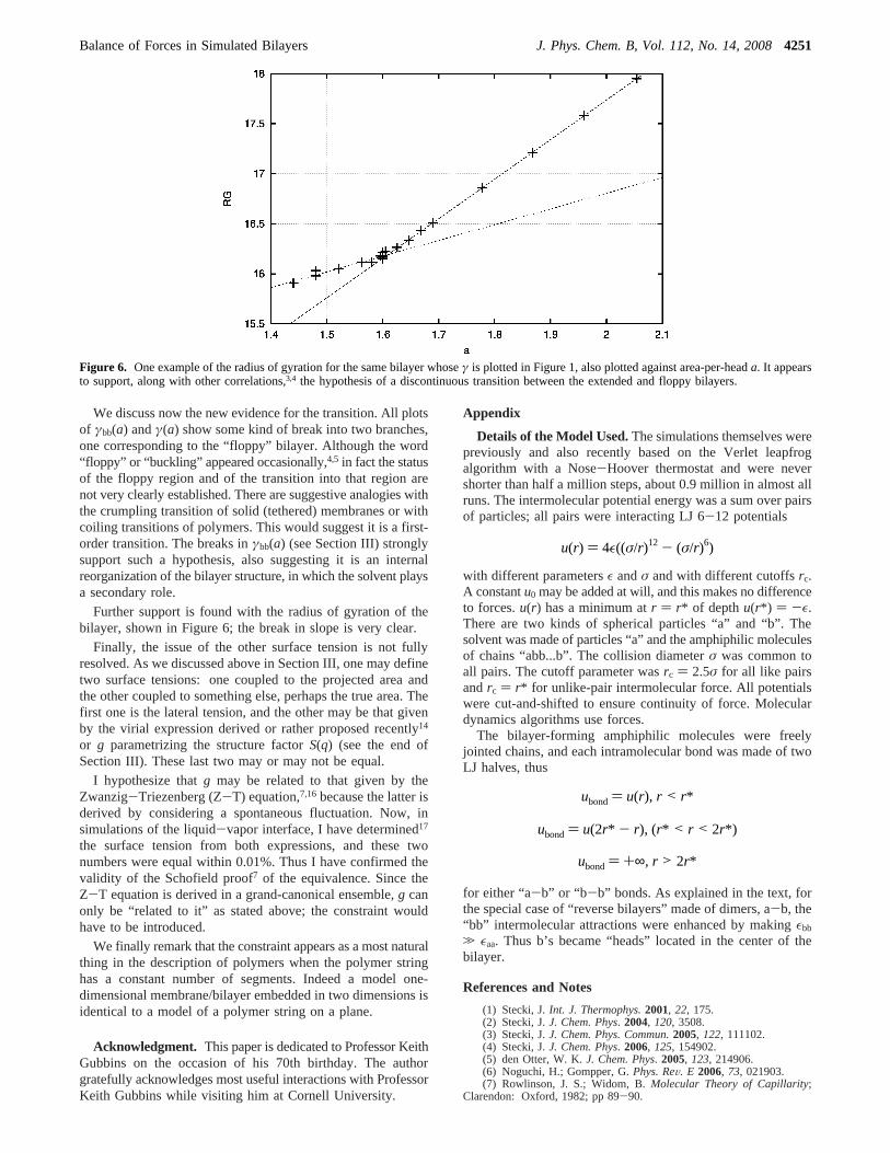
We discuss now the new evidence for the transition. All plotsof γbb(a) andγ(a) show some kind of break into two branches,one corresponding to the “floppy” bilayer. Although the word“floppy” or “buckling” appeared occasionally,4,5 in fact the statusof the floppy region and of the transition into that region arenot very clearly established. There are suggestive analogies withthe crumpling transition of solid (tethered) membranes or withcoiling transitions of polymers. This would suggest it is a first-order transition. The breaks inγbb(a) (see Section III) stronglysupport such a hypothesis, also suggesting it is an internalreorganization of the bilayer structure, in which the solvent playsa secondary role.
Further support is found with the radius of gyration of thebilayer, shown in Figure 6; the break in slope is very clear.
Finally, the issue of the other surface tension is not fullyresolved. As we discussed above in Section III, one may definetwo surface tensions: one coupled to the projected area andthe other coupled to something else, perhaps the true area. Thefirst one is the lateral tension, and the other may be that givenby the virial expression derived or rather proposed recently14
or g parametrizing the structure factorS(q) (see the end ofSection III). These last two may or may not be equal.
I hypothesize thatg may be related to that given by theZwanzig-Triezenberg (Z-T) equation,7,16because the latter isderived by considering a spontaneous fluctuation. Now, insimulations of the liquid-vapor interface, I have determined17
the surface tension from both expressions, and these twonumbers were equal within 0.01%. Thus I have confirmed thevalidity of the Schofield proof7 of the equivalence. Since theZ-T equation is derived in a grand-canonical ensemble,g canonly be “related to it” as stated above; the constraint wouldhave to be introduced.
We finally remark that the constraint appears as a most naturalthing in the description of polymers when the polymer stringhas a constant number of segments. Indeed a model one-dimensional membrane/bilayer embedded in two dimensions isidentical to a model of a polymer string on a plane.
Acknowledgment. This paper is dedicated to Professor KeithGubbins on the occasion of his 70th birthday. The authorgratefully acknowledges most useful interactions with ProfessorKeith Gubbins while visiting him at Cornell University.
Appendix
Details of the Model Used.The simulations themselves werepreviously and also recently based on the Verlet leapfrogalgorithm with a Nose-Hoover thermostat and were nevershorter than half a million steps, about 0.9 million in almost allruns. The intermolecular potential energy was a sum over pairsof particles; all pairs were interacting LJ 6-12 potentials
with different parametersε andσ and with different cutoffsrc.A constantu0 may be added at will, and this makes no differenceto forces.u(r) has a minimum atr ) r* of depth u(r*) ) -ε.There are two kinds of spherical particles “a” and “b”. Thesolvent was made of particles “a” and the amphiphilic moleculesof chains “abb...b”. The collision diameterσ was common toall pairs. The cutoff parameter wasrc ) 2.5σ for all like pairsandrc ) r* for unlike-pair intermolecular force. All potentialswere cut-and-shifted to ensure continuity of force. Moleculardynamics algorithms use forces.
The bilayer-forming amphiphilic molecules were freelyjointed chains, and each intramolecular bond was made of twoLJ halves, thus
for either “a-b” or “b-b” bonds. As explained in the text, forthe special case of “reverse bilayers” made of dimers, a-b, the“bb” intermolecular attractions were enhanced by makingεbb
. εaa. Thus b’s became “heads” located in the center of thebilayer.
References and Notes
(1) Stecki, J.Int. J. Thermophys.2001, 22, 175.(2) Stecki, J.J. Chem. Phys. 2004, 120, 3508.(3) Stecki, J.J. Chem. Phys. Commun.2005, 122, 111102.(4) Stecki, J.J. Chem. Phys. 2006, 125, 154902.(5) den Otter, W. K.J. Chem. Phys. 2005, 123, 214906.(6) Noguchi, H.; Gompper, G.Phys. ReV. E 2006, 73, 021903.(7) Rowlinson, J. S.; Widom, B.Molecular Theory of Capillarity;
Clarendon: Oxford, 1982; pp 89-90.
Figure 6. One example of the radius of gyration for the same bilayer whoseγ is plotted in Figure 1, also plotted against area-per-heada. It appearsto support, along with other correlations,3,4 the hypothesis of a discontinuous transition between the extended and floppy bilayers.
u(r) ) 4ε((σ/r)12 - (σ/r)6)
ubond) u(r), r < r*
ubond) u(2r* - r), (r* < r < 2r*)
ubond) +∞, r > 2r*
Balance of Forces in Simulated Bilayers J. Phys. Chem. B, Vol. 112, No. 14, 20084251

(8) Rowlinson, J. S.Cohesion; Cambridge University Press: Cam-bridge, U.K., 2002.
(9) Goetz, R.; Lipowsky, R.J. Chem. Phys. 1998, 108, 7397.(10) Gompper, G.; Goetz, R.; Lipowsky, R.Phys. ReV. Lett. 1999, 82,
221.(11) Imparato, A.; Shilcock, J. C.; Lipowsky, R.Eur. Phys. J. E2003,
11, 21; see also ref 13.(12) Imparato, A.; Shilcock, J. C.; Lipowsky, R.Europhys. Lett. 2005,
69, 650.
(13) Imparato, A.J. Chem. Phys. 2006, 124, 154714.
(14) Farago, O.J. Chem. Phys.2003, 119, 596; for further work on thismodel, see Farago, O.; Pincus, P.J. Chem. Phys.2004, 120, 2934.
(15) Cooke, I. R.; Deserno, M.J. Chem. Phys.2005, 123, 224710 (seealso http://arxiv.org/PS_cache/cond-mat/pdf/0509/0509218v1/pdf.
(16) Triezenberg, D. G.; Zwanzig, R.Phys. ReV. Lett. 1972, 28, 1183.
(17) see Stecki, J.J. Chem. Phys. 2001, 114, 7574;1998, 108, 3788.
4252 J. Phys. Chem. B, Vol. 112, No. 14, 2008 Stecki