Embed Size (px)
Citation preview

CEMB S.p.A. - Via Risorgimento, 9 - MANDELLO DEL LARIO (LC) - ITALY - tel. 0341/706111
Balancing Theory and Applications(Rev. 2.1)
Ing. G. Manni
Mandello del Lario, 30.07.99

CEMB S.p.A. - Via Risorgimento, 9 - MANDELLO DEL LARIO (LC) - ITALY - tel. 0341/706111
Note from the writer
The following text reports the main arguments discussed during the balancing courses proposed by CEMBand are a record for the participants and a guiding path for the teacher .During the courses ,the different arguments are more widely explained and enriched with practicalexamples.The explanation ,even if correct ,is simple and full of useful examples , and so understandable to all thepeople (with different culture level ),interested in the balancing technology ..By mentioning the source , reproduction of parts are possible .

CEMB S.p.A. - Via Risorgimento, 9 - MANDELLO DEL LARIO (LC) - ITALY - tel. 0341/706111
INDEX
CHAPTER 1 BASIC PRINCIPLES
1.2 Balancing requirement
1.3 Unbalance(definition)
1.4 Unbalance measuring unit
1.5 Centre of mass (definition)
1.6 Mass eccentricity (definition)
1.7 Axis of inertia (definition)
1.8 Unbalance classification
1.9 Static unbalance (definition)
1.10 Couple unbalance (definition)
1.11 Dynamic unbalance
1.12 Equivalent total unbalances (equal)
1.13 Vector relationship between unbalances
1.14 Dynamic balancing
1.15 Examples of dynamic balancing
1.16 Unbalance effect
1.17 Balancing speed
1.18 Common frequent words
1.19 Criteria for deciding the number of balancing planes ( 1 or 2 ) for rigid rotors
1.20 Static balancing without the use of a balancing machine
CHAPTER 2 BANANCING TOLERANCES
1.21 Foreword
1.22 Balance quality grades for various groups of representative rigid rotors
1.23 Balancing tolerance
1.24 Examples of calculation of the residual unbalance according to ISO 1940/1 Standards for rigid rotors .
1.25 Evaluation of the balancing quality G (The total residual unbalance is known)
1.26 Balancing tolerances according to API 610 standards
Balancing tolerances calculated according to the maximum admitted load on the bearings
1.27 Allocation of permissible residual unbalance to each correction plane according to ISO 1940/1
1.28 Static / couple unbalance with narrow balancing planes
1.29 Balancing tolerance / balancing planes
1.30 Balancing certificate

CEMB S.p.A. - Via Risorgimento, 9 - MANDELLO DEL LARIO (LC) - ITALY - tel. 0341/706111
Cap. 3 CHAPTER 3 MOUNTING ADAPTERS
3.1 Foreword
3.2 Coupling accuracy evaluation
3.3 Basic principles to design a mounting adapter
3.4 Examples of mounting adapters
3.5 Common errors caused by the Adapters
3.6 Electronic compensation for mounting adapters errors.(eccentricity compensation)
3.7 Manual compensation for mounting adapter errors (eccentricity correction)
3.8 Example for evaluating the error caused by a coupling sleeve mounted eccentric
3.9 Basic concepts for adapter eccentricity correction
3.10 Balancing of rotors shafts without fitments ;rotor shaft key convention
3.11 Balancing the fitment (flywheel ,coupling , etc.) with an adapter having a full key
CHAPTER 4 ON FIELD BALANCING
Foreword
Necessary equipment
Theory
Test mass calculation method
Two planes balancing on service conditions
Not linear response
Manual unbalance calculation with the graphic vector method
Evaluation of the optimum angle position of the test mass during calibration
Manual balancing with the use of a simple vibration meter
CHAPTER 5 FLEXIBLE ROTORS BALANCING
Foreword
Shaft critic (natural ) speed evaluation methods
Calculation of the critic (natural ) speed
Natural frequencies of a beam calculation
Rotors classification
Rotor flexibility measurement on a balancing machine
Basic criteria for flexible rotors balancing
Rotors classification according to balancing requirements
Quasi rigid rotors
Examples of low speed balancing
Flexible rotors
Number of balancing planes

CEMB S.p.A. - Via Risorgimento, 9 - MANDELLO DEL LARIO (LC) - ITALY - tel. 0341/706111
Modal balancing
Modal balancing test masses set
Influence coefficients method
Balancing tolerances for flexible rotors
Flexible shaft bending evaluation (Whirl)
CHAPTER 6 THE BALANCING MACHINES
Industrial balancing machines classification
Unbalance transducers and support mechanics
Horizontal axis balancing machine support
Horizontal axis hard bearing balancing machine support equipped with piezoelectric transducers
Vertical axis dynamic balancing machine equipped with piezoelectric pick ups.
Unbalance calculation mode
Main differences between hard and soft balancing technology
Error occurring when using a soft bearing machine for static unbalance measuring
Hard bearing balancing machine proper use
Working range of a variable speed hard bearing balancing machine
Specific calibration balancing on a hard bearing machine (Self learning of influence coefficients)
Different types of cradles used for rotors balancing
CHAPTER 7 BALANCING METHODS FOR MOS COMMON CASES
Crankshafts
Propeller shafts
Propeller shaft body balancing (No flexible joints)
Fan impellers
Pump impellers
Paper rolls
Vehicle turbo chargers
Hydraulic couplings
Tools and toolholder balancing
Car wheels
Plough shafts
Centrifugal separators
Electric armatures
Textile machines components
Relationship Unbalance-drill depth
CHAPTER 8 BALANCING MACHINE CONTROL

CEMB S.p.A. - Via Risorgimento, 9 - MANDELLO DEL LARIO (LC) - ITALY - tel. 0341/706111
Test rotor
Calibration control
Balancing machine test according to ISO 2953
Balancing machine control according to ISO 9000 standards .
CHAPTER 9 REFERENCES

Cap. I - 7
CEMB S.p.A. - Via Risorgimento, 9 - MANDELLO DEL LARIO (LC) - ITALY - tel. 0341/706111
CHAPTER 1
BASIC PRINCIPLES
1.1 Balancing requirement
Unbalance control and measure of rotating bodies is today more and more important for different reasons:
1) Higher and higher operating speeds (more production)
2) Lighter frames (lower production costs)
3) Service speed near to critical speeds (technologic or space reasons do not allow more rigid frames)
4) Longer life for each parts (bearings for instance) for a reduced load
5) Lower maintenance costs (for repair and change)
6) Longer machines availability (less production stops)
It is important to point out that the measure of the unbalance is an overall control placed at the end of theproduction line (it reveals errors on dimension tolerances,casting faults,uneven parts) and it is an index forthe quality of the final product.

Cap. I - 8
CEMB S.p.A. - Via Risorgimento, 9 - MANDELLO DEL LARIO (LC) - ITALY - tel. 0341/706111
1.2 Unbalance(definition)
Not uniform mass distribution around the axis of rotation
A Rotor is unbalanced when its mass is not evenly distributed around the axis of rotationFrom definition it is clear that it makes no sense to speak of unbalance without defining the axis of rotation,that is the ideal line around which the mass distribution is considered
Example:
Balanced section Unbalanced section
Every rotor can be divided into different sections (perpendicular to the axis of rotation) having each one itsown unbalance.As consequence we call local unbalance (of the section i) the value
jji rmU ⋅= ∑where iU is the unbalance of the section i (described by a vector normal to the axis of rotation),
jm are the single masses belonging to the section i
jr are the distances of the component masses to the axis of rotation
The symbol ∑ means vectors addition.
From definition it is clear that the unbalance of a section is the mass static moment calculated with referenceto the axis of rotationTotal unbalance tU is the set of local unbalances and is mathematically described by the following formula
{ }it UU =

Cap. I - 9
CEMB S.p.A. - Via Risorgimento, 9 - MANDELLO DEL LARIO (LC) - ITALY - tel. 0341/706111
1.3 Unbalance measuring unit
Please refer to the following drawing which shows a perfectly balanced section (U = 0), on which adisturbing mass m has been added on point P at a distance from the axis of rotation equal to rAdded mass m causes an unbalance U, (vector with direction P-O and value equal to m·r.)
Unbalance measuring unit is:gr mm⋅
mass distance from the axis of rotation
U m r= ⋅ = ⋅ = ⋅10 100 1000gr mm gr mm
Same value for U = 1000 gr·mm can be obtained with a mass of 20 gr on a radius of 50 mm (placed in thesame angular position)In fact we obtain U = 20 gr · 50 mm = 1000 gr·mm 50

Cap. I - 10
CEMB S.p.A. - Via Risorgimento, 9 - MANDELLO DEL LARIO (LC) - ITALY - tel. 0341/706111
1.4 Centre of mass (definition)
Point around which the mass static moment is equal to zero.
With regard to the centre of mass following relationship is valid
m ri i∑ = 0
wheremr
i
i
=
=
generica massa
distanza massa - centro di massa
Calculation example
We obtain: mmgr 75sinistra) a orientato (Vettore 253 11 ⋅=×=⋅ rmmmgr 75destra) a orientato (Vettore 751 22 ⋅=×=⋅ rm
(The words mass centre or gravity centre are used indifferently
The centre of mass of a system is important because its motion can be described as the sum of the masscentre plus the motion of the single parts around it.
From unbalance and centre of mass definitions it follows that , if the mass centre of a section lays on the axisof rotation, the section is perfectly balanced;, that is: U = 0.

Cap. I - 11
CEMB S.p.A. - Via Risorgimento, 9 - MANDELLO DEL LARIO (LC) - ITALY - tel. 0341/706111
1.5 Mass eccentricity (definition)
Distance between the centre of mass and the axis of rotation
Please refer to next picture where an unbalance U , mounted on a perfectly balanced section ,moves theposition of the mass centre .The added mass moves the centre of mass position ,which was originally on the geometric centre (axis ofrotation), to the right side
The distance between the centre of mass and the axis of rotation (Eccentricity) is calculated with thefollowing formula
[ ] [ ][ ]E
UM
micronsgr mm
kgμ μ: = = =
⋅ 100010
100
where M = massa in kg del rotante, U = squilibrio in gr·mm, E = eccentricità in microns(To be more precise value M+m should be placed in the denominator)
From the previous formula it is clear that:
1) The unbalance of a body U [gr·mm] is equal to the product of its mass M [kg] times its eccentricity E [μ] A pulley which is mounted not concentric (eccentric) on the motor shaft, generates ,under serviceconditions , high vibrations caused by the unbalance;).Following formula is valid
U [gr·mm] = E [μ] · M [kg]
2) Eccentricity E (ratio between the unbalance of a rotor and its mass) is also called specific unbalance (thatis unbalance per unit of mass).

Cap. I - 12
CEMB S.p.A. - Via Risorgimento, 9 - MANDELLO DEL LARIO (LC) - ITALY - tel. 0341/706111
1.6 Axis of inertia (definition)
Line around which the mass static moment is equal to zero
From the definition it follows:m ri i∑ = 0
where: mi = generica massa elementare
ri = distanza della generica massa elementare dall' asse di inerzia
From the definitions of axis of inertia and unbalance of a rotor it follows that a rotor is perfectly balanced(Ut = 0) if its axis of rotation is the same axis as the axis of inertiathe meaning is that a rotor is balanced if its mass is evenly distributed around the axis of rotation which is atthe same time axis of inertia

Cap. I - 13
CEMB S.p.A. - Via Risorgimento, 9 - MANDELLO DEL LARIO (LC) - ITALY - tel. 0341/706111
1.7 Unbalance classification
The unbalance of a rotor (set of local unbalances) can be drawn as a set of parallel vectors starting from theaxis of rotation
{ }it UU =
where sezioni) varie(delle locali squilibri
totalesquilibrio
=
=
i
t
U
U
Each vector of the above figure describes the unbalance of a single section of the rotor.
It is worth to point out that it is impossible to measure the total unbalance of a rotor ,because it requires themeasure of the unbalances for each section (which ,in the most cases it is not possible)

Cap. I - 14
CEMB S.p.A. - Via Risorgimento, 9 - MANDELLO DEL LARIO (LC) - ITALY - tel. 0341/706111
1.8 Static unbalance (definition)The total unbalance is called static if it is equivalent to a single unbalance vector placed in a section whichcontains also the centre of mass of the rotor.(The axis of inertia is parallel to the axis of rotation)
if the equivalent vector Ut is not located in one section containing also the centre of mass , we call it quasi-static unbalance.
(In the practice most people call static unbalance the total equivalent unbalance when it is placed in a singleplane only)

Cap. I - 15
CEMB S.p.A. - Via Risorgimento, 9 - MANDELLO DEL LARIO (LC) - ITALY - tel. 0341/706111
1.9 Couple unbalance (definition)
The total unbalance is called as couple unbalance if the equivalent unbalance is made by two vectors,placedon two different planes. having equal values (amplitudes) and opposite directions (The axis of inertia cuts the axis of rotation passing through the centre of mass)
The measuring unit for couple unbalance Uc is by definition equal to [ ]U d⋅ = ⋅ ⋅ = ⋅gr mm mm gr mm2
Of course values Us e Ud (unbalance value in the two sections) are equal.
For example ,if the declared couple unbalance value is 6000 gr.cm.cm ,and the distance between the twobalancing planes is 15 cm , then the unbalance per plane is 6000/15 =400gr.cm (4000 g.mm ) .If ,thebalancing radius on each plane is 20 cm ,then the unbalance per plane is 400/20=20grams .(the twounbalances on each plane are equal in value ,but opposite in the angle position )
Cap. I - 16
CEMB S.p.A. - Via Risorgimento, 9 - MANDELLO DEL LARIO (LC) - ITALY - tel. 0341/706111
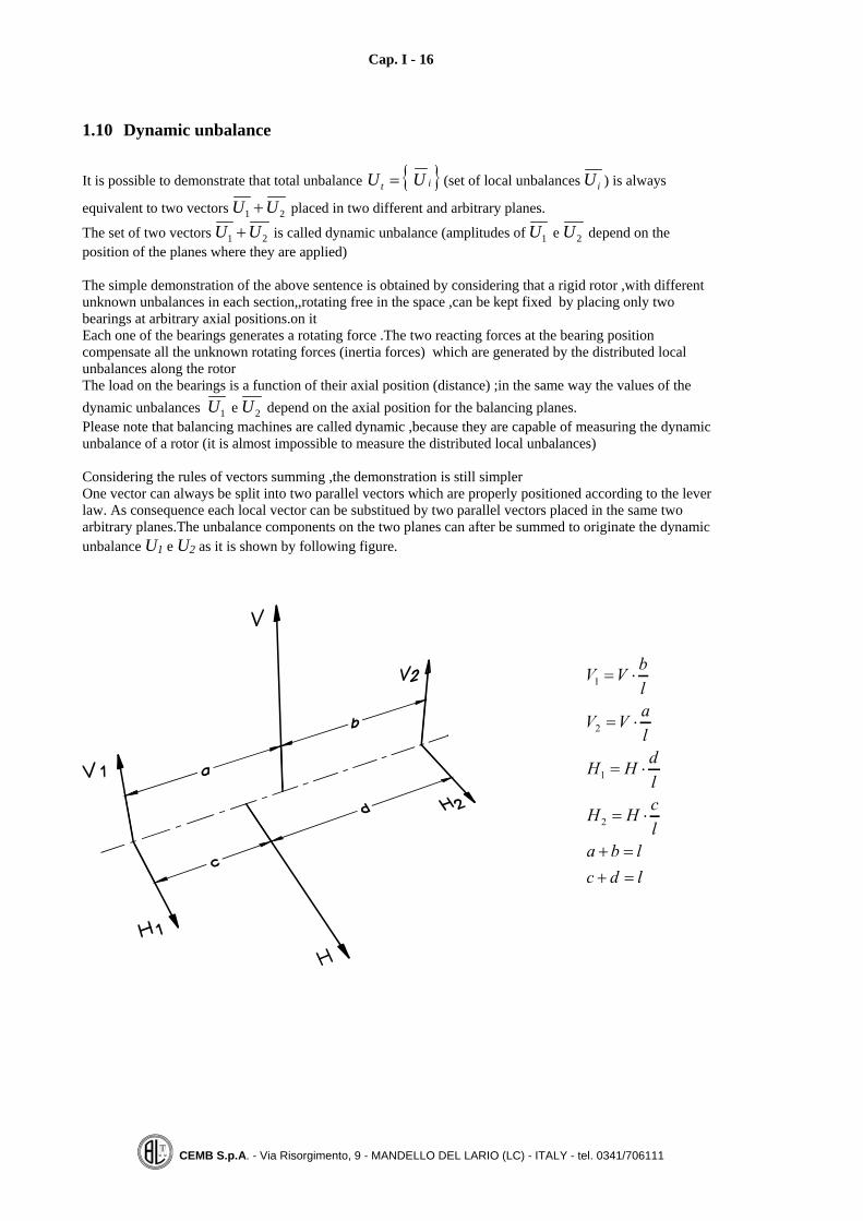
1.10 Dynamic unbalance
It is possible to demonstrate that total unbalance { }it UU = (set of local unbalances Ui ) is always
equivalent to two vectors U U1 2+ placed in two different and arbitrary planes.
The set of two vectors U U1 2+ is called dynamic unbalance (amplitudes of U1 e U2 depend on theposition of the planes where they are applied)
The simple demonstration of the above sentence is obtained by considering that a rigid rotor ,with differentunknown unbalances in each section,,rotating free in the space ,can be kept fixed by placing only twobearings at arbitrary axial positions.on itEach one of the bearings generates a rotating force .The two reacting forces at the bearing positioncompensate all the unknown rotating forces (inertia forces) which are generated by the distributed localunbalances along the rotorThe load on the bearings is a function of their axial position (distance) ;in the same way the values of thedynamic unbalances U1 e U2 depend on the axial position for the balancing planes.Please note that balancing machines are called dynamic ,because they are capable of measuring the dynamicunbalance of a rotor (it is almost impossible to measure the distributed local unbalances)
Considering the rules of vectors summing ,the demonstration is still simplerOne vector can always be split into two parallel vectors which are properly positioned according to the leverlaw. As consequence each local vector can be substitued by two parallel vectors placed in the same twoarbitrary planes.The unbalance components on the two planes can after be summed to originate the dynamicunbalance U1 e U2 as it is shown by following figure.

Cap. I - 17
CEMB S.p.A. - Via Risorgimento, 9 - MANDELLO DEL LARIO (LC) - ITALY - tel. 0341/706111
Rotor having a total unbalance Ut = just one vector placed on the right hand side
Example Nr.1: Equivalent dynamic unbalance placed on narrow planes at the same side
The rotor is mounted overhang and cosequently high load on the bearing is generated. The dynamic unbalance equivalent to Ut located on the two selected planes is U1 = 2Ut , U2 = 3Ut
Example Nr.2: Dynamic unbalance placed on two different places
Placing the bearings at long distance at rotor ends,lower loads are generatedThe equivalent dynamic unbalance calculated for the new planes (bearings), is: U1 = 0 , U2 = Ut
Cap. I - 18
CEMB S.p.A. - Via Risorgimento, 9 - MANDELLO DEL LARIO (LC) - ITALY - tel. 0341/706111
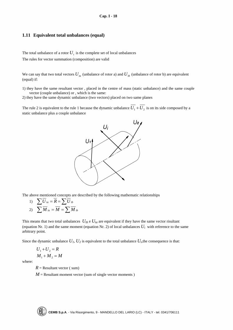
1.11 Equivalent total unbalances (equal)
The total unbalance of a rotor Ut is the complete set of local unbalancesThe rules for vector summation (composition) are valid
We can say that two total vectors Uta (unbalance of rotor a) and Utb (unbalance of rotor b) are equivalent(equal) if:
1) they have the same resultant vector , placed in the centre of mass (static unbalance) and the same couplevector (couple unbalance) or , which is the same:
2) they have the same dynamic unbalance (two vectors) placed on two same planes
The rule 2 is equivalent to the rule 1 because the dynamic unbalance U U1 2+ is on its side composed by astatic unbalance plus a couple unbalance
The above mentioned concepts are described by the following mathematic relationships1) ∑∑ == ibia URU
2) ∑∑ == ibia MMM
This means that two total unbalances Utb e Uta are equivalent if they have the same vector risultant(equation Nr. 1) and the same moment (equation Nr. 2) of local unbalances Ui with reference to the samearbitrary point.
Since the dynamic unbalance U1, U2 is equivalent to the total unbalance Ut,the consequence is that:
RUU =+ 21
MMM =+ 21where:
R = Resultant vector ( sum)
M = Resultant moment vector (sum of single vector moments )
Cap. I - 19
CEMB S.p.A. - Via Risorgimento, 9 - MANDELLO DEL LARIO (LC) - ITALY - tel. 0341/706111
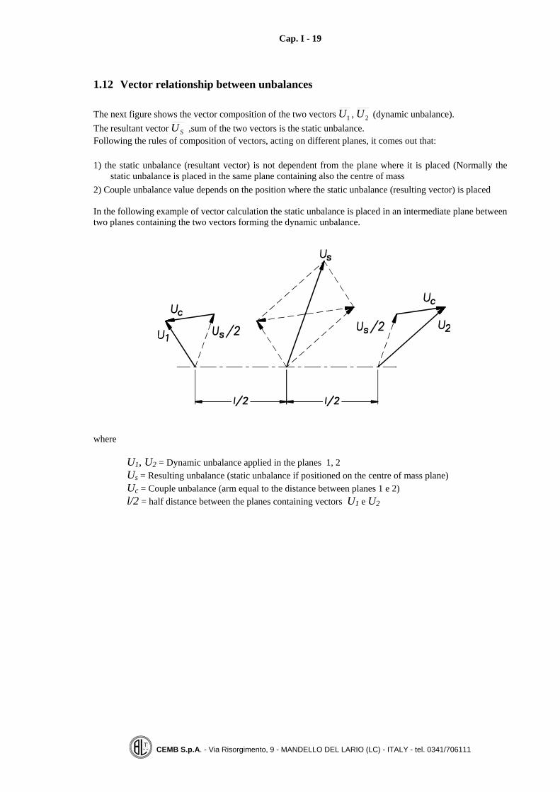
1.12 Vector relationship between unbalances
The next figure shows the vector composition of the two vectors U1 , U2 (dynamic unbalance).The resultant vector US ,sum of the two vectors is the static unbalance.Following the rules of composition of vectors, acting on different planes, it comes out that:
1) the static unbalance (resultant vector) is not dependent from the plane where it is placed (Normally thestatic unbalance is placed in the same plane containing also the centre of mass
2) Couple unbalance value depends on the position where the static unbalance (resulting vector) is placed
In the following example of vector calculation the static unbalance is placed in an intermediate plane betweentwo planes containing the two vectors forming the dynamic unbalance.
where
U1, U2 = Dynamic unbalance applied in the planes 1, 2Us = Resulting unbalance (static unbalance if positioned on the centre of mass plane)Uc = Couple unbalance (arm equal to the distance between planes 1 e 2)l/2 = half distance between the planes containing vectors U1 e U2

Cap. I - 20
CEMB S.p.A. - Via Risorgimento, 9 - MANDELLO DEL LARIO (LC) - ITALY - tel. 0341/706111
1.13 Dynamic balancing
• Dynamic balancing a rotor means to reduce its dynamic unbalance to zero or better to acceptable levels
• The dynamic unbalance is by definition U U1 2+ , ;so it is necessary to operate on two different planes
• Since the dynamic unbalance equivalent to the total unbalance Ut can be calculated with reference totwo arbitrary planes, the consequence is that the two balancing planes (where material can be added orremoved)can be arbitrary chosen
What above reported is valid only for rigid rotors , where mass distribution (local unbalances) does not varywith the speed.

Cap. I - 21
CEMB S.p.A. - Via Risorgimento, 9 - MANDELLO DEL LARIO (LC) - ITALY - tel. 0341/706111
1.14 Examples of dynamic balancing
a) Original unbalance placed in one plane only
a).1 One plane balancing
a).2 Two planes balancing

Cap. I - 22
CEMB S.p.A. - Via Risorgimento, 9 - MANDELLO DEL LARIO (LC) - ITALY - tel. 0341/706111
b) Couple unbalance balancing
b).1 Balancing on two distant planes
b).2 Balancing on narrow planes

Cap. I - 23
CEMB S.p.A. - Via Risorgimento, 9 - MANDELLO DEL LARIO (LC) - ITALY - tel. 0341/706111
It is easy to verify that ,after the balancing operation ,both the resultant vector both the moment of vectors,calculated with reference to an arbitrary plane, are equal to zeroFrom the above reported examples ,it is clear that a rotor can be balanced in different ways depending on theelected balancing planesIn order to balance doing the minimum effort two rules are valid
1) To choose balancing planes as far as possible
2) To choose balancing radius as large as possible
Important note: by the dynamic balancing, acting on two different planes, the total unbalance ( set oflocal unbalances )is not reduced to zero ; only the dynamic unbalance (on two planes ) equivalent tothe total unbalance UT is reduced to zero

Cap. I - 24
CEMB S.p.A. - Via Risorgimento, 9 - MANDELLO DEL LARIO (LC) - ITALY - tel. 0341/706111
1.15 Unbalance effect
An unbalanced rotor generates an inertial force (centrifugal) which increases with the square speed.
F m r U= ⋅ ⋅ = ⋅ω ω2 2
where
ωπ
=⋅2
60N
where
minute
srevolution=N
F = Centrifugal force in Newton
The vector unbalance U (multiplied by the factor ω2 , square of the angular speed ) originates the centrifugalforce F ; this means that the load caused by the unbalance increases with the square of the speed (doublingthe running speed the centrifugal force ( inertia force ) becomes four times greater);
Note: In the MKSA system distance is measured in meters [m] ;as a consequence the unbalance should bemeasured in kg·m. following relationship is valid 1 kg·m = 106 gr·mm.

Cap. I - 25
CEMB S.p.A. - Via Risorgimento, 9 - MANDELLO DEL LARIO (LC) - ITALY - tel. 0341/706111
1.16 Balancing speedThe unbalance of a rotor is caused by the radial distribution of its masses along its axis of rotation; theconsequence is that ,if the rotor is rigid and this means that the values and relative positions of its masses donot change ,the unbalance does not change with the speed.In a rigid rotor the operating speed does not modify mass distribution and consequently has no influence onthe unbalance.By adding a 20 gr mass at a defined radial position on a perfectly balanced disc an unbalance is generated ;this unbalance does not change with the speed because in order to reset the original conditions , it is justnecessary to remove the added 20 gr mass, and this independently on rotor speedFor rigid rotors the balancing speed is not to be specified ; because it is related only to machine sensitivityand not to the rotor unbalance which is under measurement.Modern hard bearing balancing machines have the capability to measure the dynamic unbalance starting from70 RPMThe unbalance effect (centrifugal force) increases with the speed ;the electric signal increases at the samrtime , so machine sensitivity tends to increase, because of a better ratio signal to noiseDepending on the model and manufacturer ,optimum sensitivity values are obtainable starting from 400 600RPM.
Note Not expert people make confusion between the cause (unbalance) with its effect (centrifugal force orvibration). The effect increases with the speed ,while the cause (unbalance) ,in a rigid body does not change.

Cap. I - 26
CEMB S.p.A. - Via Risorgimento, 9 - MANDELLO DEL LARIO (LC) - ITALY - tel. 0341/706111
1.17 Common frequent words
Static balancing : Unbalance measuring and correction is done in one plane only.
Dynamic balancing : Unbalance measuring and correction is done in two different planes.
Correction planes : è It is the section (plane? Normal to rotor axis where unbalance correction isperformed by adding or removing masses.

Cap. I - 27
CEMB S.p.A. - Via Risorgimento, 9 - MANDELLO DEL LARIO (LC) - ITALY - tel. 0341/706111
1.18 Criteria for deciding the number of balancing planes ( 1 or 2 ) for rigid rotorsFrom the previous explanation it is clear that the total unbalance of a rotor is equivalent to a dynamicunbalance ( two unbalances placed on two arbitrary planes) ; only in special cases the total unbalance isequivqlent to a single unbalance placed in one plane (static unbalance).). The consequence is that a rotor is tobe balanced dynamically on two planes). Notwithstanding , in the practical application ,good results areobtained sometimes acting on one plane only. The selection (one or two planes )is made according to thefollowing table ..With reference to the following table , where l and d are respectively rotor length and diameter reportedcriteria are valid .Exceptions are possible according to the acquired experience . Please note that the speedplays a big role ; higher the speed better balancing (dynamic) is requested
Useful table to decide ,(as function of the speed and rotor geometric dimensions) the necessity of balancingin one plane (static ) or in two planes (dynamic
Service speed (RPM)ld
Number of balancing planes
< 200 whichever 1da 200 a 1200 < 0,5 1da 200 a 1200 > 0,5 2da 1200 a 3600 < 0,15 1da 1200 a 3600 > 0,15 2
> 3600> 0,05Disc shaped rotors
21
Cap. I - 28
CEMB S.p.A. - Via Risorgimento, 9 - MANDELLO DEL LARIO (LC) - ITALY - tel. 0341/706111
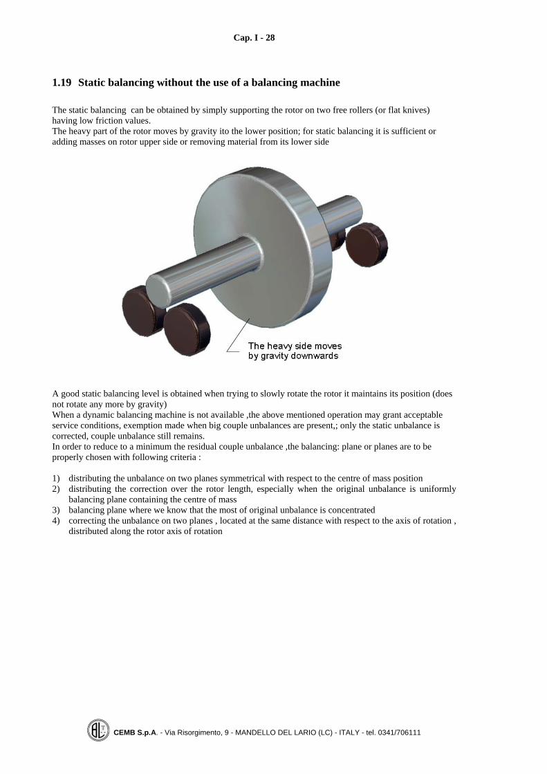
1.19 Static balancing without the use of a balancing machine
The static balancing can be obtained by simply supporting the rotor on two free rollers (or flat knives)having low friction values.The heavy part of the rotor moves by gravity ito the lower position; for static balancing it is sufficient oradding masses on rotor upper side or removing material from its lower side
A good static balancing level is obtained when trying to slowly rotate the rotor it maintains its position (doesnot rotate any more by gravity)When a dynamic balancing machine is not available ,the above mentioned operation may grant acceptableservice conditions, exemption made when big couple unbalances are present,; only the static unbalance iscorrected, couple unbalance still remains.In order to reduce to a minimum the residual couple unbalance ,the balancing: plane or planes are to beproperly chosen with following criteria :
1) distributing the unbalance on two planes symmetrical with respect to the centre of mass position2) distributing the correction over the rotor length, especially when the original unbalance is uniformly
balancing plane containing the centre of mass3) balancing plane where we know that the most of original unbalance is concentrated4) correcting the unbalance on two planes , located at the same distance with respect to the axis of rotation ,
distributed along the rotor axis of rotation

Cap. II - 29
CEMB S.p.A. - Via Risorgimento, 9 - MANDELLO DEL LARIO (LC) - ITALY - tel. 0341/706111
CHAPTER 2
BALANCING TOLERANCES
2.1 ForewordThe balancing of a rotating body has different goals:1) reduced load on the bearings (low centrifugal forces)2) long bearings life3) acceptable vibration levels (a good vibration level does not create any problems to the comfort or to
component life.From previous point 3 , it is clear that the optimum value for the residual unbalance can be evaluated in anexperimental mode , by considering that:a) The inertia force generated by the unbalance can be calculated using the formula reported on paragrath
1.15;b) On service vibrations levels can be easily measured with a simple vibrometer.For each application an acceptable value for the admitted residual unbalance (which grants goodperformances ) can be defined..ISO 1940 standards gives a rule in order to calculate an acceptable residual unbalance ,having followingfeatures:
1) gross unbalance deficiencies are avoided,2) useless and excessive balancing works are avoided
For each rotor type,(depending on its maximum service speed) the acceptable total residual unbalance per
unit of mass is calculated ⎥⎦
⎤⎢⎣
⎡ ⋅kg
mmgr (specific residual unbalance).
The calculated value is the same mass eccentricity defined on paragraph 1.5; so following relationship isvalid:
[ ]MUE =μ
where: E = Mass eccentricity [microns]U = Unbalance [gr·mm]M = Rotor mass [kg]
According to ISO 1940 standards ,all rotors are classified (grouped) ,depending on their balancingrequirements (look at following table). Balancing quality G is anumber which defines the balancing accuracyrequired ; for instance G = 2,5 means that a fine balancing is requered, G = 6,3 means that a normalbalancing is accepted.Please note that the measuring unit for G is mm/s, because this value represents the vibration speed assumedby the body rotating freely in the space at the real service speed.The same value of vibration speed ( G=mm/s) is achieved by the rotor ,when it rotates mounted on a softbearing machine at service speed.
Following relationship is valid:1000
ω⋅=
EG
where: G = balance quality (grade) [mm/s]E = eccentricity [microns] ϖ = angular speed ] [rad/s]

Cap. II - 30
CEMB S.p.A. - Via Risorgimento, 9 - MANDELLO DEL LARIO (LC) - ITALY - tel. 0341/706111
2.2 Balance quality grades for various groups of representative rigid rotors
Note: Some groups of rotors ,not included in official ISO table , are added and reported in Italic types ..
Balancing
qualitygrade
Gmm/s
ROTOR TYPES
0,4 GyroscopesSpindles, discs and armatures of precision grindersTextile fuses
1,0 Small electric armatures with special requirementsTape recorder and phonograph (gramophone) drives, cine projectorsGrinding machine drivesTurbines and Compressors with special requirements
2,5 Gas and steam turbines, including marine main turbines (merchant service)Turbine driven pumpsRigid turbo generator rotorsTurbo compressorsHigh speed compressors and aeronautic compressorsMedium and large electric armatures with special requerimentsHigh quality household electric armatures ,dentist drills .textile componentsSmall electric armatures not qualifying for one or both of the conditions specified for small electric armaturesof balance quality grade G6,3Machine tool driveAir conditioning fans for Hospitals and concert hallsHigh speed gears(over 1000 RPM) of marine turbines .Computer memory drums and discs
6,3 Small electric armatures ,often mass produced , in vibration insensitive applications and / or with vibrationisolating mountingsMedium and large electric armatures (of electric motors having at least 80 mm shaft height ) without specialrequirementsMachine tool and general machinery partsParts of process plant machines , Centrifuge drums, decanters, washersHydraulic machine rotorsFly wheels , Fans ; Pump impellersMarine main tuebine gears (merchant service )Paper machinery rolls ; print rollsAssembled aircraft gas turbine rotorsIndividual components of engines under special requirements
16 Drive shafts(propeller shafts , cardan shafts ) with special requirementsParts of agricultural machinery, parts of crushing machinesIndividual components of engines (gasoline or diesel) for cars ,trucks and locomotivesCrankshaft / drives of engines with six or more cylinders under special requirementsLow speed separatorsLight boat impellers)Motor bicycle and car wheelsNormal transmission pulley Wood machine tools
40 Car wheels ,wheel rims ,wheel sets .drive shaftsCrankshaft / drives of elastically mounted fast four cycle engines (gasoline or diesel ) with six or morecylinders (pistons speed greater than 9 m/sCrankshaft /drives of engines of cars , trucks and locomotives

Cap. II - 31
CEMB S.p.A. - Via Risorgimento, 9 - MANDELLO DEL LARIO (LC) - ITALY - tel. 0341/706111
2.3 Balancing tolerance
The following drawing defines the required tolerance according to ISO 1940/1.standards

Cap. II - 32
CEMB S.p.A. - Via Risorgimento, 9 - MANDELLO DEL LARIO (LC) - ITALY - tel. 0341/706111
the previous table defines the required balancing quality G according to each rotor type. The maximum service speed is reported on the orizontal x axis , while the acceptable specific unbalance(acceptable unbalance per unit of mass or acceptable residual mass eccentricity ) is reported on the vertical y
axis The following formula can be used instead of previous diagram: ( ) GN
Et ⋅=μ9550
where: Et [μ] = total acceptable mass eccentricityN [RPM] = Maximum service rotor speedG [mm/s] = Balancing quality or grade
Total residual accepted unbalance: U [gr·mm] = Et·Mwhere: M [kg] = Rotor mass
Total residual admitted unbalance in grams is RUm = where R [mm] is the compensation radius.

Cap. II - 33
CEMB S.p.A. - Via Risorgimento, 9 - MANDELLO DEL LARIO (LC) - ITALY - tel. 0341/706111
2.4 Examples of calculation of the residual unbalance according to ISO 1940/1Standards for rigid rotors .
Example N°1 – Fun impeller
Maximum service speed = 1500 RPM
Mass M = 200 kg
Left , right side correction radius Rs = Rd = 800 mm
Balancing quality G = 6,3
From previous diagram we obtain:
Tatal acceptable residual eccentricity et = 40 μ
Total acceptable residual unbalance Ut = M·e = 200 kg x 40 μ = 8000 gr x mm
8000 gr x mm (Total acceptable unbalance)
4000 gr x mm 4000 gr x mm(acceptable unbalance for
left plane)(acceptable unbalance for
right plane)
Per plane acceptable unbalance in grams 5gr4000/8005gr4000/800
==
⟨=⋅
=Rmmgr
Note: The acceptable unbalance per plane has been calculated by simply dividing by two the total acceptableunbalance ; this operation is correct because the two balancing planes have almost the same distance fromthe centre of mass position .,which is at the same time almost in the centre of the rotor.

Cap. II - 34
CEMB S.p.A. - Via Risorgimento, 9 - MANDELLO DEL LARIO (LC) - ITALY - tel. 0341/706111
Example N°2 – Turbine
Maximun service speed = 3000 RPM
Rotor mass M = 500 kg
Left side balancing radius Rs = 500 mm
Right side balancing radius Rd = 400 mm
Balance quality G = 2,5
From previous diagram we obtain:
Total acceptable residual eccentricity et = 8 μ
By using the formula ( ) GN
Et ⋅=μ9550
we obtain: μ≅⋅= 85.230009550
tE
The total acceptable unbalance Ut = M·e = 500 kg x 8 μ = 4000 gr x mm
4000 gr x mm (Squilibrio totale ammissibile)
2000 gr x mm 2000 gr x mmsquilibrio ammissibile piano
sinistrosquilibrio ammissibile piano
destro
The accepted unbalance value on the left plane is ( )Us = =2000500
4gr 1,7
The accepted unbalance value for the right plane is ( )Ud = =2000400
5gr 2
Values within brackets are valid for the quality G = 1 (quality g 1 is nowadays commonly required forturbines )
Cap. II - 35
CEMB S.p.A. - Via Risorgimento, 9 - MANDELLO DEL LARIO (LC) - ITALY - tel. 0341/706111
Example N°3 – Impeller of a centrifugal pump
Maximum service speed = 6000 RPM
Mass M = 10 kg
Balancing radius R = 100 mm
Required balancing quality G = 6.3
From previous diagram we obtain:
Total acceptable residual eccentricity et = 10 μ
By using the formula ( ) GN
Et ⋅=μ9550
we obtain: μ≅⋅= 103.660009550
tE
The total acceptable unbalance Ut = M·e = 10 kg x 10 μ = 100 gr x mm
The total acceptable unbalance in grams (for the correction radius of 100 mm) is gr1mm100
mmgr100=
⋅==
RU
Note: Since the impeller is thin (reduced axial dimentions ) it is balanced in one plane only ( Staticbalancing)

Cap. II - 36
CEMB S.p.A. - Via Risorgimento, 9 - MANDELLO DEL LARIO (LC) - ITALY - tel. 0341/706111
Example N°4 – Tool holder dynamically balanced
The tool holder has a useful length L bigger than 2D (where D is the cone diameter ).Considering its length it is advisable to balance it on two planes.
Maximum service speed = 24'000 RPM
Tool holder mass M = 5 kg
Correction radius on balancing plane 1 R1 40 mm
Correction radius on balancing plane 2 R2 20 mm
Required balancing quality G = 2,5(ISO standards specify quality G=2.5 for machine tools spindles and driving systems)
Total acceptable residual eccentricity E = 1 μ
Total acceptable residual unbalance Ut = M·E = 5 kg x 1 μ = 5 gr x mm
5 gr x mm (Squilibrio totale ammissibile)
2,5 gr x mm 2,5 gr x mm(squilibrio ammesso nel
piano sinistro)(squilibrio ammesso nel
piano destro)
Acceptable unbalance on plane 1 U1 (in grams) grmm
mmgr 06,0405,2
=⋅
=
Acceptable unbalance on plane 2 U2 (in grams) grmm
mmgr 125,0205,2
=⋅
=
Note: The total acceptable unbalance has been divided by two because we assumed that tool holder mass ismore or less symmetrical with regard to the centre of mass position ,and that the two correction planescontain the centre of mass almost in the middle position.

Cap. II - 37
CEMB S.p.A. - Via Risorgimento, 9 - MANDELLO DEL LARIO (LC) - ITALY - tel. 0341/706111
Example N°5 – Tool holder balanced in one plane only
Let us consider a tool holder which is to be balanced in one plane (static balancing).Normally the tool holder is balanced in one plane only , if its length L is lower than 2D.(D is cone diameter)
Maximum service speed = 12'000 RPM
Tool holder mass M = 1 kg
Balancing radius = 20 mm
Balancing quality G = 1(ISO standards specify quality G 1 for grinding machine spindles)
Total acceptable eccentricity E = 2 μ
Total acceptable residual unbalance Ut = M·E = 1 kg x 2 μ = 2 gr x mm
Total acceptable unbalance in the correction radius U (in grams) grmmmmgr 1,0
202
=⋅
=
Cap. II - 38
CEMB S.p.A. - Via Risorgimento, 9 - MANDELLO DEL LARIO (LC) - ITALY - tel. 0341/706111
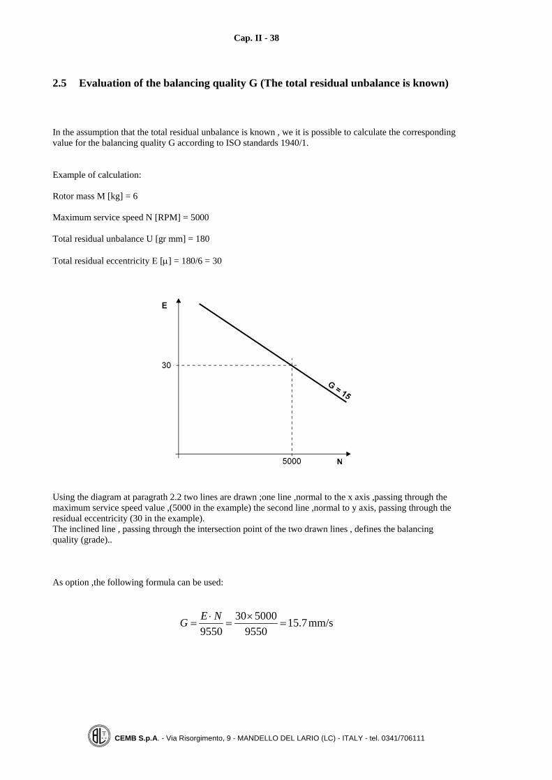
2.5 Evaluation of the balancing quality G (The total residual unbalance is known)
In the assumption that the total residual unbalance is known , we it is possible to calculate the correspondingvalue for the balancing quality G according to ISO standards 1940/1.
Example of calculation:
Rotor mass M [kg] = 6
Maximum service speed N [RPM] = 5000
Total residual unbalance U [gr mm] = 180
Total residual eccentricity E [μ] = 180/6 = 30
Using the diagram at paragrath 2.2 two lines are drawn ;one line ,normal to the x axis ,passing through themaximum service speed value ,(5000 in the example) the second line ,normal to y axis, passing through theresidual eccentricity (30 in the example).The inclined line , passing through the intersection point of the two drawn lines , defines the balancingquality (grade)..
As option ,the following formula can be used:
mm/s7.159550
5000309550
=×
=⋅
=NEG
Cap. II - 39
CEMB S.p.A. - Via Risorgimento, 9 - MANDELLO DEL LARIO (LC) - ITALY - tel. 0341/706111
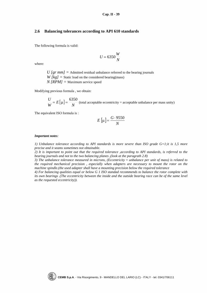
2.6 Balancing tolerances according to API 610 standards
The following formula is valid:
UWN
= 6350 where:
U [gr mm] = Admitted residual unbalance referred to the bearing journalsW [kg] = Static load on the considered bearing(mass)N [RPM] = Maximum service speed
Modifying previous formula , we obtain:
[ ]UW
EN
= =μ6350
(total acceptable eccentricity = acceptable unbalance per mass unity)
The equivalent ISO formula is :
[ ]N
GE 9550⋅=μ
Important notes:
1) Unbalance tolerance according to API standards is more severe than ISO grade G=1;it is 1,5 moreprecise and it seams sometimes not obtainable.2) It is important to point out that the required tolerance ,according to API standards, is referred to thebearing journals and not to the two balancing planes ,(look at the paragrath 2.8)3) The unbalance tolerance measured in microns, (Eccentricity = unbalance per unit of mass) is related tothe required mechanical precision , especially when adapters are necessary to mount the rotor on themachine spindle.(the used adapter shall have a mounting precision below the required tolerance4) For balancing qualities equal or below G 1 ISO standad recommends to balance the rotor complete withits own bearings .(The eccentricity between the inside and the outside bearing race can be of the same levelas the requested eccentricity)).
Cap. II - 40
CEMB S.p.A. - Via Risorgimento, 9 - MANDELLO DEL LARIO (LC) - ITALY - tel. 0341/706111
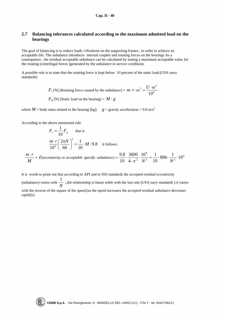
2.7 Balancing tolerances calculated according to the maximum admitted load on thebearings
The goal of balancing is to reduce loads /vibrations on the supporting frames , in order to achieve anacceptable life. The unbalance introduces internal couples and rotating forces on the bearings As aconsequence , the residual acceptable unbalance can be calculated by stating a maximum acceptable value forthe rotating (centrifugal forces )generated by the unbalance in service conditions
A possible rule is to state that the rotating force is kept below 10 percent of the static load.(USA navystandards)
Fr [N] (Rotating force caused by the unbalance) = 6
22
10ω⋅
=ω⋅⋅Urm
Fg [N] (Static load on the bearing) = gM ⋅
where M = body mass related to the bearing [kg]; g = gravity acceleration = 9.8 m/s2
According to the above mentioned rule
gr FF101
= that is
8.9101
602
10
2
6 ⋅⋅=⎟⎠⎞
⎜⎝⎛ π⋅ MNrm
it follows:
622
6
2 10189610110
43600
108.9
)ority(eccentric ⋅⋅⋅=⋅⋅
⋅==⋅
NNE
Mrm
unbalancespecificacceptableπ
It is worth to point out that according to API and to ISO standards the accepted residual eccentricity
(unbalance) varies with N1
;,the relationship is linear while with the last rule (USA navy standards ) it varies
with the inverse of the square of the speed.(as the speed increases the accepted residual unbalance decreasesrapidily)
Cap. II - 41
CEMB S.p.A. - Via Risorgimento, 9 - MANDELLO DEL LARIO (LC) - ITALY - tel. 0341/706111
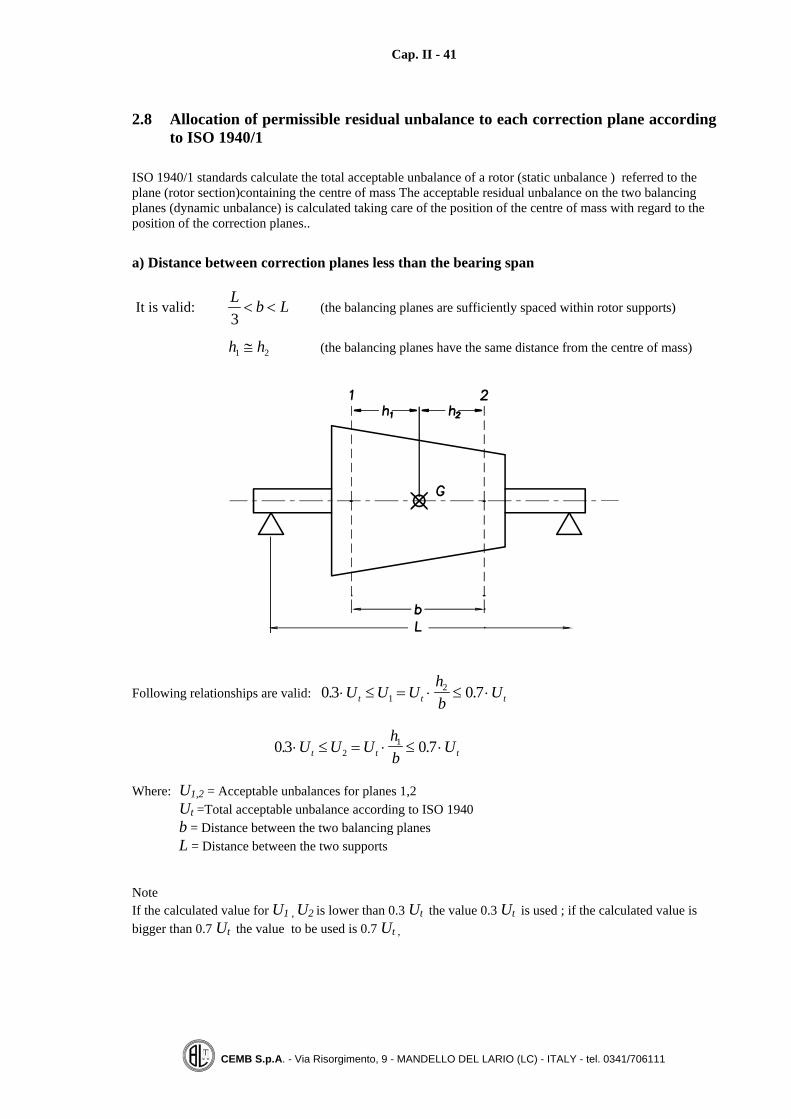
2.8 Allocation of permissible residual unbalance to each correction plane accordingto ISO 1940/1
ISO 1940/1 standards calculate the total acceptable unbalance of a rotor (static unbalance ) referred to theplane (rotor section)containing the centre of mass The acceptable residual unbalance on the two balancingplanes (dynamic unbalance) is calculated taking care of the position of the centre of mass with regard to theposition of the correction planes..
a) Distance between correction planes less than the bearing span
It is valid: LbL<<
3(the balancing planes are sufficiently spaced within rotor supports)
21 hh ≅ (the balancing planes have the same distance from the centre of mass)
Following relationships are valid: 0 3 0 712. .⋅ ≤ = ⋅ ≤ ⋅U U U
hb
Ut t t
0 3 0 721. .⋅ ≤ = ⋅ ≤ ⋅U U U
hb
Ut t t
Where: U1,2 = Acceptable unbalances for planes 1,2Ut =Total acceptable unbalance according to ISO 1940b = Distance between the two balancing planesL = Distance between the two supports
NoteIf the calculated value for U1 , U2 is lower than 0.3 Ut the value 0.3 Ut is used ; if the calculated value isbigger than 0.7 Ut the value to be used is 0.7 Ut ,

Cap. II - 42
CEMB S.p.A. - Via Risorgimento, 9 - MANDELLO DEL LARIO (LC) - ITALY - tel. 0341/706111
b) Distance between the balancing planes much greater than the bearing distance
In this case the couple unbalance on balancing planes 1, 2 has the bigger effect on the supports.The acceptable unbalance value on planes 1, 2 is given by following formula :
U U ULbt1 2, = ⋅
where Ut = total acceptable unbalance according to ISO 1040/1.

Cap. II - 43
CEMB S.p.A. - Via Risorgimento, 9 - MANDELLO DEL LARIO (LC) - ITALY - tel. 0341/706111
c) Balancing planes distance lower than 1/3 supports distance
(b is lower than L/3)
An arbitrary plane is chosen for the static unbalance (it can be plane 1 or 2).
stU (referred to plane 3) CLU t
22⋅=
The acceptable residual unbalance is kept between 2
tU e
4tU
cU (referred to planes 1, 2) bLU t ⋅⋅=
43
2The couple unbalance is greater than tU
In other terms the acceptable unbalance for each plane 1, 2 is bigger than Ut
2 ;its value is ::
UU L
bLC
t1 2 2
34 2, = +⎛⎝⎜
⎞⎠⎟
Under the condition that the static unbalance is lower than UU L
Cstt= ⋅
2 2
Note: the above reported formulas are valid under the condition that the rotor supports are equal

Cap. II - 44
CEMB S.p.A. - Via Risorgimento, 9 - MANDELLO DEL LARIO (LC) - ITALY - tel. 0341/706111
A frequent application of the above mentioned rules happens with pump and fun impellers (over hangmounted.)
Exemple: One stage over hang pump
L = 400 mm Service speed = 1500 RPMb = 50 mm Rotor mass = 50 kgC = 500 mm G = 6,3
From ISO diagram ( G = 6,3 ) we obtain Et = 40 μ
Ut = × = ⋅40 50 2000 gr mm
UU L
Cst= ⋅ = ⋅
⋅= ⋅
2 22000
2400
2 500400 gr mm
UU L
bct= ⋅ ⋅ = ⋅ ⋅ = ⋅
234
20002
34
40050
6000 gr mm
If the static unbalance Us ≤ ⋅400 gr mm , the acceptable value on the two balancing planes 1, 2 can be≤ ⋅6400 gr mm
UU L
bLC
t1 2 2
34 2, ≤ +⎛⎝⎜
⎞⎠⎟
(It is worth to point out that the acceptable value on each balancing plane is bigger than the total unbalance)

Cap. II - 45
CEMB S.p.A. - Via Risorgimento, 9 - MANDELLO DEL LARIO (LC) - ITALY - tel. 0341/706111
2.9 Static / couple unbalance with narrow balancing planes
When balancing on narrow planes , it is necessary to distinguish between static and couple unbalance,because the two types of unbalances have a different effects on the supports..
Example 1: Pure static unbalance
The following figure shows the effects ,on the rotor supports ,generated by a static unbalance applied on aover hang pump impeller. Support loads are calculated according to the laws of static M = 0 ; R = 0 (Theconditions for equilibrium are that the momentum and the resultant of all forces are zero).
The load on the support nearer to the impeller is bigger and its value is ⎟⎠⎞
⎜⎝⎛ +
4001001stU
The load on the farther support is lower and its value is 400100
stU
The conclusion is that the static unbalance mainly has a direct effect on the nearer support .

Cap. II - 46
CEMB S.p.A. - Via Risorgimento, 9 - MANDELLO DEL LARIO (LC) - ITALY - tel. 0341/706111
Example 2: Couple unbalance
The next figure shows the effect generated by a couple unbalance on the supports of an over hang impeller
The effect of couple unbalance is reduced by the ratio of the arms
U UU
cc
supporto = ⋅ =40
400 10
For the above mentioned reason different values for static and couple unbalances are specified ;for instance:Static unbalance tolerance = 1 gr mmDynamic unbalance tolerance(couple) = 4 gr mm per plane
For instance , for axial fun impeller (width30÷40 mm and an external diameter of300÷400 mm ) the normal required tolerance onthe static unbalance is 30÷50 gr mm while acouple unbalance of 100÷200 gr mm .is accepted.

Cap. II - 47
CEMB S.p.A. - Via Risorgimento, 9 - MANDELLO DEL LARIO (LC) - ITALY - tel. 0341/706111
2.10 Balancing tolerance / balancing planes
Let us consider a rotor having a pure couple unbalance of 15 gr mm placed on two different planes with100 mm distanceUc = ⋅ × = ⋅15 100 1500 gr mm mm gr mm2
Taking as reference the previous figure , it is clear that , depending on the position (distance ) of the twoselected balancing planes ,the measured unbalance which is to be corrected varies (30, 15, 10 gr mm).If the acceptable balancing value per plane is 15 gr mm ,then the rotor is considered within tolerance only ifthe two balancing planes are placed on the supporting position or at a distance of 100 mm; for shorterdistances balancing planes the rotor is no more within toleranceNow ,a rotor should be considered properly balanced (within tolerance ) indifferently of the two selectedbalancing planes.As a consequence a correct unbalance tolerance can be specified in two ways by defining .
1) A tolerance on the static unbalance (referred to a specified plane) and a tolerance on the couple unbalance2) A dynamic tolerance U a1 e U a2 specifying also the two balancing planes .
ISO 1940/1 specifies a total tolerance Ut placed on a balancing plane which contains the centre of mass.
API standard specifies the admitted dynamic unbalance (on two planes ) placed on the bearing journals.

Cap. II - 48
CEMB S.p.A. - Via Risorgimento, 9 - MANDELLO DEL LARIO (LC) - ITALY - tel. 0341/706111
Defining a limit value (balancing tolerance) for the unbalance referred to the bearing journal directly gives alimitation to the rotating forces which exert on it.This is particularly useful ,because an acceptable residual unbalance calculated with the above mentionedrule , is valid whichever are the two selected balancing planes.API 612 e 613 standards use this rule and calculate the residual acceptable unbalance with the followingformula
Um
n1 2
61 2
2
89 451 10,
,.]=
× ×⋅ [gr mm where:
nm==numero di giri al minuto
massa gravante sul supporto 1,2 [kg]1 2,
The calculated value for the acceptable residual unbalance grants that the rotating centrifugal force ,acting onthe support, is lower than ten percent of the static load(weight).
For calculating the residual acceptable eccentricity ,the following formula is valid :
Ent =×89451 106
2.
per2,5)Ge1Gtraintermedio(valore
ISO)secondo2,5G (circa
5.2 RPM 6000 10 RPM 3000
==
=
μ≅=μ≅=
t
t
EnEn
it is very important:To avoid any confusion between the actual balancing planes (where we act ) and the two planes where the
unbalance tolerance is specified.To specify always. in a clear way , the two planes where the acceptable residual unbalance is valid.
With the use of a modern microprocessor measuring unit,it is possible to specify the tolerance on the twobalancing planes or on the two rotor supports..To specify the unbalance tolerance on the two rotor supports ,it is sufficient to set the parameters A = C = 0and the parameter B = Supports distance (look chap. 6, par. 3).If Ut is the total acceptable residual unbalance (calculated according to an accepted standard, ISO 1940 f. i.)in the most of cases ,when the two supports are similar ,the acceptable residual unbalance per each support is:
U UU
A At
1 2 2= =
where U UA A1 2, = Acceptable unbalance in each support plane 1, 2

Cap. II - 49
CEMB S.p.A. - Via Risorgimento, 9 - MANDELLO DEL LARIO (LC) - ITALY - tel. 0341/706111
2.11 Balancing certificate
In order to verify / certify the balancing quality ,a good balancing certificate must contain the followinginformations:
1) ROTOR TYPEIt is useful to define the necessary balancing quality
2) ROTOR MASS and SERVICE SPEEDThey are useful to calculate the residual unbalance and to verify if the rotor is a rigid or a flexible one
3) BALANCING METHODSResting position on the balancing machine (they define the actual axis of rotation), position of actualbalancing planes , correction radius, balancing by adding or removing.
4) UNBALANCE DATAOriginal and residual unbalance on the two balancing planes
5) USED BALANCING MACHINE AND SPEED Useful data to verify the machine sensitivity and if it is suitable.
In the following page an example for a balancing certificate is reportedThe certificate can be completed with the following data:• Original unbalance• Unbalance angular position

Cap. II - 50
CEMB S.p.A. - Via Risorgimento, 9 - MANDELLO DEL LARIO (LC) - ITALY - tel. 0341/706111

Cap. III - 51
CEMB S.p.A. - Via Risorgimento, 9 - MANDELLO DEL LARIO (LC) - ITALY - tel. 0341/706111
CHAPTER 3
MOUNTING ADAPTERS
3.1 Foreword
Many types of rotors ,produced also on big volumes , (for instance pulleys, flying wheels, pumps and funsimpellers etc..) , on service conditions are connected with a key to their driving shafts . In order to be bal-anced they require a proper adapter to mount them on a balancing machine .The balancing machine measures the unbalance of the rotating part (rotor plus adapter ); as a consequence anideal adapter should :
- Have a very low unbalance (equal to zero )
- Reproduce ,in the balancing machine ,the same axis of rotation existing in service conditions
The compliance of the above mentioned criteria is limited mostly by mechanical problems (geometric toler-ances and centring accuracy).It is not rare the case when perfectly balanced rotors , are mounted eccentric in service conditions and conse-quently generate high unbalances and vibrations.To avoid this problem and in order to not destroy the achieved balancing conditions , same rotors are centred,on service conditions , with a conic shaft (centrifugal separators .).A cylinder type mounting , always causes centring errors (unbalances ) because of the mechanic couplingshaft / hole (different geometric values within the specified mechanic tolerance )The balancing machine is responsible for the unbalance of the rotor and the balancing condition can be di-rectly verified on the machine itself , by measuring the unbalance with the rotor mounted in different angularpositions.
Good service conditions of balanced rotors are possible only if :
1) Centring is correct
2) The coupling part is balanced ,too.

Cap. III - 52
CEMB S.p.A. - Via Risorgimento, 9 - MANDELLO DEL LARIO (LC) - ITALY - tel. 0341/706111
3.2 Coupling accuracy evaluation
Type of rotor = PulleyMax service speed = 3000 RPMBalancing quality G = 6,3Total acceptable eccentricity according to ISO 1940 = 20 μm
In order to grant a residual eccentricity of 20 μm , the mounting adapter must :
1) Centre the rotor with a mechanic accuracy lower than 20 microns (the electronic compensation for tool er-ror is necessary )
2) Be able to centre rotors having different diameters values caused by the manufacturing process (machiningtolerances ) which may cause random eccentricities in the mounting .
Now, considering that:
1) The required balancing quality is equal or even better than Q = 6,3 (2,5)2) The rotors , to be balanced, have necessarily a geometric tolerance (variation ) on the centring diameters .
The natural consequence is that the mounting adapters must have :
� A conical tape centring , or� An expanding type cylinder centring .
The expanding type cylinder mounting makes it easier the loading / unloading process ,no interference oc-curs.The conical centring may require an additional device to unlock the rotor and dismount it after the balancingprocess .The conical mounting ,also on the service conditions , has the advantage of not destroying the previouslyreached balancing state .The goodness of a mounting adapter (centring accuracy and repeatability) can be easily verified by measur-ing the unbalance of the rotor mounted each time in a different angular position .(a good adapter grantsreadings with a small variations ).
Cap. III - 53
CEMB S.p.A. - Via Risorgimento, 9 - MANDELLO DEL LARIO (LC) - ITALY - tel. 0341/706111
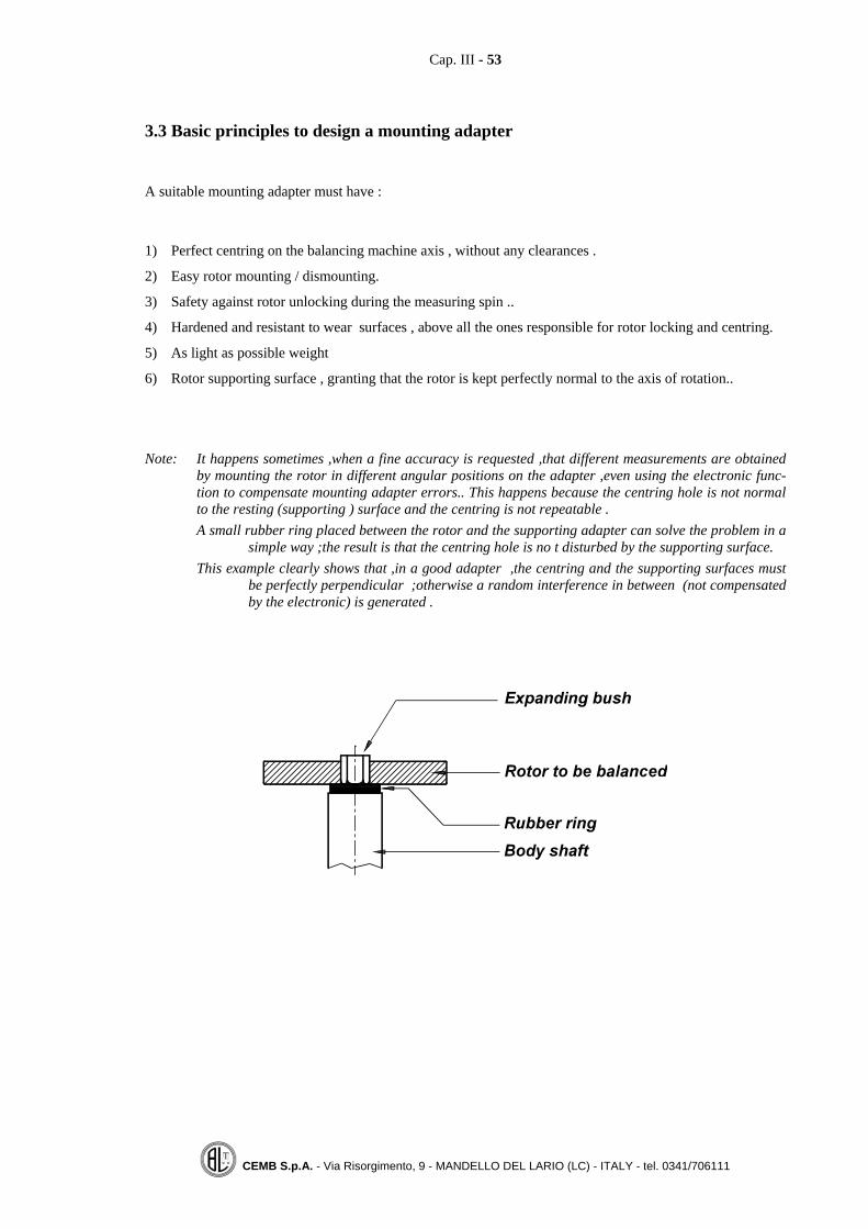
3.3 Basic principles to design a mounting adapter
A suitable mounting adapter must have :
1) Perfect centring on the balancing machine axis , without any clearances .
2) Easy rotor mounting / dismounting.
3) Safety against rotor unlocking during the measuring spin ..
4) Hardened and resistant to wear surfaces , above all the ones responsible for rotor locking and centring.
5) As light as possible weight
6) Rotor supporting surface , granting that the rotor is kept perfectly normal to the axis of rotation..
Note: It happens sometimes ,when a fine accuracy is requested ,that different measurements are obtainedby mounting the rotor in different angular positions on the adapter ,even using the electronic func-tion to compensate mounting adapter errors.. This happens because the centring hole is not normalto the resting (supporting ) surface and the centring is not repeatable .A small rubber ring placed between the rotor and the supporting adapter can solve the problem in a
simple way ;the result is that the centring hole is no t disturbed by the supporting surface.This example clearly shows that ,in a good adapter ,the centring and the supporting surfaces must
be perfectly perpendicular ;otherwise a random interference in between (not compensatedby the electronic) is generated .

Cap. III - 54
CEMB S.p.A. - Via Risorgimento, 9 - MANDELLO DEL LARIO (LC) - ITALY - tel. 0341/706111
3.4 Examples of mounting adapters
Different types of mounting tools are reported in the following
a) Rotor centring on the shaft
Simple cylinder shaft
Tapered shaft
Shaft with a cut washer
Shaft with a key
Shaft with spring washers

Cap. III - 55
CEMB S.p.A. - Via Risorgimento, 9 - MANDELLO DEL LARIO (LC) - ITALY - tel. 0341/706111
b) Rotor centring on the external cylinder surface (tool with a round hole)
Cylinder / tapered mounting
Locking by radial movable jaws(It is also used to lock from the inside big rotors diameters)
c) Centring on pins
Rotor locking on three pins at 120 degrees

Cap. III - 56
CEMB S.p.A. - Via Risorgimento, 9 - MANDELLO DEL LARIO (LC) - ITALY - tel. 0341/706111
d) Expanding type mounting tool ;to be used on a vertical axis machine.
Important features of an expanding mounting tool are ::
1) Threaded holes ,each 30 degrees , to be used to perfectly balance the tool itself..
2) Hardened tool centring shaft on the machine spindle (coupling tolerance H7).
3) Rotor resting surface ; it grants that the rotor is mounted perfectly normal to the centring hole.
4) Interchangeable expanding bush.
5) Holes (3 at 120°) used to connect the tool to the machine spindle.
6) Mobile drawbar used for a quick locking / unlocking.

Cap. III - 57
CEMB S.p.A. - Via Risorgimento, 9 - MANDELLO DEL LARIO (LC) - ITALY - tel. 0341/706111
e) Mounting tool with double centring tapered shafts (on rotor and spindle side )
Main feature of a tapered tool are :
1) Centring cone to fix the tool on the machine spindle. In the microprocessor type modern machines . theconic part can be eliminated , because the electronic is capable of correcting any eccentricity error in themounting, (look at 3.6).
2) Holes (3 at 120°) to fix the tool to the machine spindle.
3) Nut used to easy download the rotor from the adapter.(with a tapered intrference this operation could bedifficult)
4) Tapered part to centre the rotor (the cutting on the tapered part facilitates rotor extraction).

Cap. III - 58
CEMB S.p.A. - Via Risorgimento, 9 - MANDELLO DEL LARIO (LC) - ITALY - tel. 0341/706111
f) Expansion type adapter to be used on a horizontal axis balancing machine
In many practical applications with horizontal axis balancing machines , the rotors (pump or fun impellersecc.) are balanced in an over hang position , keeping the mounting adapter shaft on the balancing machineThis way the balancing operation is quicker ,the parts are easily mounted and dismountedTwo different mounting adapter shafts , based on the same principle , are.shown
The main feature of this adapter shaft are:
1) Body having a mass and a length capable of keeping the centre of mass of the assembly (tool plus rotor )within machine supports.
2) Cylinder surface granting tool centring.
3) Tool base ,interchangeable ,in order to cover a wide diameter range..
4) Expanding type bush ,interchangeable , to cover a wide diameter range

Cap. III - 59
CEMB S.p.A. - Via Risorgimento, 9 - MANDELLO DEL LARIO (LC) - ITALY - tel. 0341/706111
The next tool , similar to the previous one as a concept , makes it easy the operations of production changeand rotor mounting dismounting..
The main features of this adapter shaft are :
1) Shaft body having a mass and a length in order to maintain the centre of mass of the assembly (rotor plusadapter ) within machine supports. As option, a reverse thrust roller cradle ,capable of sustaining an up-ward force ) can be used. (look at. 6.11).
2) Tapered seat ,to centre the tool on the shaft.
3) Tool body with double conic parts ,on shaft and on rotor sides..
4) Ring nut for an easy mounting / dismounting of the tool body on the adapter shaft.
5) Expansion bush ,locked by a nut. (Expanding range : 0.5 ÷ 3 mm a depending on the diameter; centringaccuracy < 0.01 mm. With the same tool body , different bushes can be used ,in order to cover a widerange of diameters..
6) Two sets of threaded holes , each near machine supports ,tobe used for balancing the adapter shaft itself .

Cap. III - 60
CEMB S.p.A. - Via Risorgimento, 9 - MANDELLO DEL LARIO (LC) - ITALY - tel. 0341/706111
g) Adapter shaft ,with conical centring ,to be used on an horizontal axis balancing machine
Main features of the adapter are :
7) Cylinder shaped end side for connection to the balancing machine cardan drive .
8) Shaft body having a mass and a length capable to maintain the centre of mass (adapter plus rotor )within machine supports . Two sets of threaded holes ,placed near machine supports ,are used to balancethe shaft.
9) Hardened and ground surfaces Shaft supported positions on machine rollers.
10) Tapered part to centre the rotor.
Note: Special roller cradles (reverse thrust rollers or four roller cradle) mounted on the opposite machinesupport are necessary for the use of lighter mounting adapters shafts (type f or g) where the rotor,to be balanced in over hang position , generates a force in the upward direction

Cap. III - 61
CEMB S.p.A. - Via Risorgimento, 9 - MANDELLO DEL LARIO (LC) - ITALY - tel. 0341/706111
h) Car wheels mounting adapter with conical centring
The above reported adapter is currently used to balance car wheels .The main features are :
1) Tool body with a cylinder centring to the machine spindle .
2) Rim resting surface (it grants the ortogonality).
3) Centring cone ; it is changeable in order to cover different diameters .
4) Air operated , rim quick locking system.

Cap. III - 62
CEMB S.p.A. - Via Risorgimento, 9 - MANDELLO DEL LARIO (LC) - ITALY - tel. 0341/706111
i) Segment type adapter
The mounting tools , using expanding bushes sliding on a conical shaft , have an accuracy (mechanic repeat-ability) lower than 0.01 mm (10 microns). The expanding bush has a geometric run out ,even small , betweenthe inside and the outside diameter . This run out (constant error) can be compensated by a modern measur-ing unit ,under the condition that the bush does not change its angular position on tool shaft (pls.refer to nextsketch ).
An expanding type tool with reduced errors (~ 5 microns) is made by expanding segments. The movablesegments are placed in repetitive positions , as a consequence , the related errors can be measured and com-pensated by the measuring unit . The segment type tool is moreover safer against the possible entrance ofsmall chips . (To avoid the same problem ,the bush slots are filled up with rubber )
1) Tool body with its centring and connecting part to the machine spindle.
2) Rotor supporting system. It is composed by three supports at 120 degrees , with same open space in be-tween , in order to allow chips outgoing .
3) N° 5 radial moving segments
4) Air operated draw bar whose movement causes the opening of the segments.
Two reference pins at 180°avoid bush rotation keeping itin a fixed position (no centringerrors
Cap. III - 63
CEMB S.p.A. - Via Risorgimento, 9 - MANDELLO DEL LARIO (LC) - ITALY - tel. 0341/706111
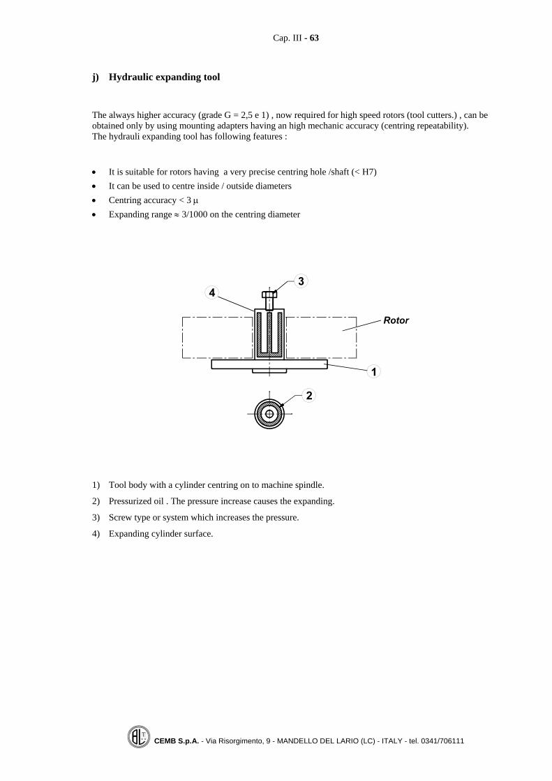
j) Hydraulic expanding tool
The always higher accuracy (grade G = 2,5 e 1) , now required for high speed rotors (tool cutters.) , can beobtained only by using mounting adapters having an high mechanic accuracy (centring repeatability).The hydrauli expanding tool has following features :
• It is suitable for rotors having a very precise centring hole /shaft (< H7)• It can be used to centre inside / outside diameters• Centring accuracy < 3 μ• Expanding range ≈ 3/1000 on the centring diameter
1) Tool body with a cylinder centring on to machine spindle.
2) Pressurized oil . The pressure increase causes the expanding.
3) Screw type or system which increases the pressure.
4) Expanding cylinder surface.

Cap. III - 64
CEMB S.p.A. - Via Risorgimento, 9 - MANDELLO DEL LARIO (LC) - ITALY - tel. 0341/706111
3.5 Common errors caused by the Adapters
The balancing machine measures the unbalance of the complete rotating part (rotor plus mounting adapter).
We are interested to measure the unbalance of the rotor only ,as better as possible .
The errors caused by mounting adapters can be divided in :
a) Repeatable (constant ) errors ,due to :
• Balancing machine spindle unbalance• Adapter unbalance• Adapter mounted eccentric on the balancing machine spindle (it is equivalent to an unbalance)• Rotor mounted eccentric von the adapter (it is equivalent to an unbalance)
b) Not repeatable errors (random) due to :
• Mechanic clearances rotor / adapter• Normal mechanic variation on centring diameters (production tolerances)
Constant errors can be totally compensated by the measuring unit ; while not repeatable errors can only bereduced (not completely eliminated ) by using high precision type adapters , which can be of two types :
Expanding type ,cylinder shape (accuracy : 2 ÷ 5 μm)
Conical centring (accuracy : 1 ÷ 3 μm).

Cap. III - 65
CEMB S.p.A. - Via Risorgimento, 9 - MANDELLO DEL LARIO (LC) - ITALY - tel. 0341/706111
3.6 Electronic compensation for mounting adapters errors (eccentricity compensa-tion)
A modern microprocessor measuring unit is capable to compensate (null) the errors (type A, look 3.5) causedby the mounting adapter .Step by step operations are :
1) Carefully clean the adapter and the machine spindle surfaces .
2) Fix the adapter to the machine spindle
3) Mount the master rotor (a rotor equal to the others , but geometrically good and with a low unbalancevalue )
4) Set up rotor parameters.(A, B, C, R1, R2)
5) Make a first spin .
6) Turn the rotor on the adapter by 180°.
7) Make a second spin.
At each following measuring spin ,the balancing machine displays the unbalance of the rotor only ;the previ-ously calculated tool error is taken away .The electronic compensation for the adapter errors can be improved by rotating the rotor on the adapter sev-eral times (by 120 or 180 degrees) and measuring at each time the related unbalance .(this way an occasionalbad reading has a lower effect)A more precise way takes 8 readings ,one each 45 degreesIn some modern automatic machines all the procedure is automatically done
Note:1) The eccentricity (adapter ) compensation can be verified by measuring the unbalance several times ,
with the rotor mounted on the adapter in different angular positions ;the measured values (rotor unbal-ance without tool errors) should be the same.
2) The adapter error compensating procedure, is to be repeated each time the adapter is mounted on themachine spindle.
3) If the same adapter is used for another rotor type (different mass) the tool compensation procedure is tobe repeated .
4) The adapter centring error in [gr·mm] is E·m where E , in micron, is the radial eccentricity caused bythe adapter ,and m [kg] is rotor mass ..
5) Better results are obtained if master rotors , with good geometric dimensions and lower unbalance val-ues ,are used .

Cap. III - 66
CEMB S.p.A. - Via Risorgimento, 9 - MANDELLO DEL LARIO (LC) - ITALY - tel. 0341/706111
3.7 Manual compensation for mounting adapter errors (eccentricity correction)
By using common plasticine , it is possible to eliminate the repetitive (constant ) errors introduced by themounting adapter (eccentricity compensation) ,in the following way :
1) Accurately clean adapter and machine spindle surfaces.
2) Fix the adapter to the machine spindle
3) Set up balancing parametrs (A,B,C,R1,R2).
4) Spin and balance the adapter ,normally in one plane (the correction is made on the adapter itself ).
5) Mount a master rotor (a rotor geometrically representing the set , having a low unbalance value )
6) Spin and balance , by adding plasticine to the rotor (rotor unbalance and adapter errors are compen-sated).
7) Rotate by 180° the rotor on the adapter
8) Spin and measure the unbalance (the measured value is twice the error introduced by the adapter).
9) Compensate half the value ( in gr mm ) on the rotor , half the value on the adapter (plasticine can beused). The correction is made equally on the rotor and on the adapter ; for instance , if the measured un-balance (step 8 ) is 10 grams on a radius R=100 mm, 5 grams are added to the rotor at 100 mm radiusand 10 grams are added to the adapter on a 50 mm radius.
10) Repeat steps 6, 7, 8,9 one or more times until the measured unbalance is far below the required residualunbalance.
If the measured unbalance value does not decrease , it means that the adapter is not suitable .The unbalance,measured just after having rotated the rotor , is twice the adapter error .If adapter compensation has come to a positive end ,the measured value of unbalance refer to the rotor only(adapter errors are cut off ) . The same unbalance value is measured by mounting the rotor on the adapter in-differently on the angular position 0° e 180°.

Cap. III - 67
CEMB S.p.A. - Via Risorgimento, 9 - MANDELLO DEL LARIO (LC) - ITALY - tel. 0341/706111
3.8 Example for evaluating the error caused by a coupling sleeve mounted eccentric
In an end drive balancing machine ,a not perfectly centred coupling sleeve can cause an unbalance ; this erroris calculated as an example.
Rotor mass = 50 kgMaximum service speed = 3000 RPMQ = 2,5Total acceptable residual eccentricity: = 8 μmTotal residual acceptable unbalance Ut = × = ⋅50 8 400 gr mm
Mass of the driving coupling = 2 kgRadial mounting eccentricity = 100 μmUnbalance caused by the driving coupling = 2 kg x 100 μm = 200 gr mm
Special case occurring frequently:
If a residual unbalance value is to be granted on a fixed angular position of the rotor ,it is convenient to use amounting adapter having an unbalance of the same value placed in the opposite angular position ;balancingthe assembly (rotor plus adapter ) to zero ,an unbalanced rotor (of the required unbalance value and position )is obtained .).Of course ,the opposite unbalance mass is mounted on the adapter only after the tool eccentricity compensa-tion has been concluded.(look at 3.6).

Cap. III - 68
CEMB S.p.A. - Via Risorgimento, 9 - MANDELLO DEL LARIO (LC) - ITALY - tel. 0341/706111
3.9 Basic concepts for adapter eccentricity correction
In the first spin ,the rotor unbalance U and the error E. caused by the adapter are measured
In the second spin (the rotor is mounted at 180° ) , the unbalance U is rotated by 180° , while the constant er-ror ,introduced by the adapter E is still the same. These concepts are illustrated by the next figure .
It is clear that the sum L L1 2+ (first and second readings) is 2E, that is twice the error caused by the
adapter; the difference L L1 2− is two times the rotor unbalance ;that is : ULL 221 =−

Cap. III - 69
CEMB S.p.A. - Via Risorgimento, 9 - MANDELLO DEL LARIO (LC) - ITALY - tel. 0341/706111
3.10 Balancing of rotors shafts without fitments ;rotor shaft key convention
Many rotors (pulleys, flywheels , fun and pump impellers etc.) are connected to the driving shafts by a key. .Driving shafts are balanced alone without any fitment , because the same shaft can be used for different ap-plications (an electric motor shaft ca be fit with a pulley ,a pump or a fan impeller ,a coupling etc.) .Normally ,fitment (pulleys ,flywheels ) producers are different from driving shafts producers.Today ,driving shafts may be balanced in the ways ,which are to be clearly specified by the manufacturer .
a) Balancing the drive shaft with a full key
When a full key ,placed in its key way , is used for balancing the rotor without its fitment ;the end of the rotorshaft adjacent to the key way shall be permanently marked with the letter F (full key). With a modern micro-processor measuring unit , the operation of adding the key can be avoided , if a special key software is avail-able The full key belongs to the shaft ,as a consequence ,the fitment (pulley, coupling ,etc.) is balanced with-out any key. e se possibile con attrezzo a recupero di gioco. Balancing the shaft with the full key has the advantage of permitting an easier balancing of the driven part,the fitment can be balanced mounted ,in any angular position , on an expanding type adapter of a verticalaxis balancing machine ,which is best suitable for mass production.. The manufacturer of the fitment is notobliged to know the key dimensions and no particular problem arizes when the mounting adapter error com-pensation procedure is performed (look 3.6).The mounting adapter (better if expanding type ) is perfectly symmetric ..
b) Balancing the drive shaft with a half key
It avoids not useful balancing works because the empty parts are filled up; the shaft key way is filled up byits half key and is self balanced (reduced balancing work) ; the same happens for its fitment .The driving shaft is easily balanced ;quicker if a special key softer is available which allows the balancingwithout adding the half key.The end of rotor shaft adjacent to the key way shall be permanently marked with the letter H (half key).The fitment ,(coupling , pulley ,etc.) in this case , can be easily balanced under the condition that it ismounted on the adapter with a half key. (the half key can be permanently fixed on the adapter and it is evi-dent that the rotor is to be mounted in a fixed angular position ).The half key can be fixed to the mounting adapter after that the eccentricity compensation has been per-formed (look3.6) .Only under the conditions that the rotor is mounted in a fixed angular position and that the key software isavailable ,a simple expanding tool ( without the half key can be used .).The use of the half key balancing method is today recommended by ISO standards
Example of mounting adapter with an half key. The symmetric expanding bushis useful when performing the eccentricity compensation.(the rotor plus key can
be mounted at 180 )

Cap. III - 70
CEMB S.p.A. - Via Risorgimento, 9 - MANDELLO DEL LARIO (LC) - ITALY - tel. 0341/706111
3.11 Balancing the fitment (flywheel ,coupling , etc.) with an adapter having a fullkey
In many practical applications the used mounting adapter is complete with a full key for two reasons :
To supply sufficient driving torque (not obtainable with a simple expanding type adapter),To be sure that the rotor has the correct angular position on the adapter (the key softer program is used ; this
software adds a constant unbalance vector at each measuring , and therefore the rotor must be alwaysmounted in the correct angular position ).
In order to compensate for the adapter errors (mounting eccentricities , unbalances ,etc.) it is necessary to beable to mount the rotor ,on the adapter , in two opposite angular positions.(at 180 degrees )
Case a : The fitment is to be balanced without the key (the related driving rotor has been balancedwith a full key
a.1 the key software is not available
It is necessary to have a special master rotor having two key ways for mounting it at 180 degrees ,when per-forming the tool eccentricity compensation
Note : The mounting tool eccentricity compensation also balance the adapter unbalance caused by the pro-tuding half key
a.2 The key softer is available
A normal master rotor can be used (with one key way only).The body shaft of the adapter must have two key ways at 180 degrees
During the mounting adapter eccentricity compensation ,the rotor plus the key are rotated by 180The key way is then fixed to the adapter and its unbalance value is compensated by the key software at eachunbalance measuring.

Cap. III - 71
CEMB S.p.A. - Via Risorgimento, 9 - MANDELLO DEL LARIO (LC) - ITALY - tel. 0341/706111
Case b : The fitness is to be balanced with an half key (the related diving shaft has been balanced witha half key)
b.1 The key software is not availableThe adapter body shaft must have two key ways at 180 °. The tool eccentricity compensation is per-formed by rotating (same as a.2) the rotor plus the key.The key is then fixed to the adapter and an half key is also fixed in the other key opposite way.
b.2 The key software is availableSame procedure as previous point b.1 .It not more necessary to fill the second key way with an halfkey ,because it is simulated by the key software.
Note: If an automatic loading / unloading system is used ,both the balancing machine spindle ,both therotor are to be indexed to the same angular position .


Cap. IV - 73
CEMB S.p.A. - Via Risorgimento, 9 - MANDELLO DEL LARIO (LC) - ITALY - tel. 0341/706111
CHAPTER 4
ON FIELD BALANCING
4.1 Foreword
The balancing in service conditions is sometimes necessary to reduce the vibrations caused by the unbalanceof rotating parts .It compensates for different possible sources of errors ,such as :
• Mounting eccentricities• Material corrosion or accumulation• Mechanic deformations (caused by transport or temperature differences etc.)• Sum of residual unbalances (driving shaft and the coupled pulley .)
It is advisable to use only factory balanced components .The balancing operation eliminates only the synchronous vibration ,that is the component of the vibrationcaused by the unbalance , while all the other vibration components (caused for instance by misalignement orby clearances or by electric faults ) still survive .Before starting to balance ,it is important to verify the value of the synchronous vibration compared to thetotal vibration .; if its value is too low ,that is below 10% of the total value , it is necessary to find out and toeliminate the other sources otherwise the balancing operation does not introduce significant vibrationimprovements .

Cap. IV - 74
CEMB S.p.A. - Via Risorgimento, 9 - MANDELLO DEL LARIO (LC) - ITALY - tel. 0341/706111
4.2 Necessary equipment
The used measuring instrument ( vibration meter ) must be capable of separating the vibration caused by theunbalance from the total vibration .The vibration analysis (separation ) is possible with an instrument equipped with a filter .The filtering process can be :• with automatic tuning (when a photocell is used)• with manual tuning (when a stroboscopic light is used)
The stroboscopic light and the photocell are used for :• tuning (setting ) the filter on the shaft speed so that only the vibration caused by the unbalance is read• measuring the angle of the vibration (through this angle the unbalance position is calculated )
Example for angles numbering
Normally the angles are measured in the anti rotation direction. (opposite the sense of rotation )The reference mark is the zero (beginning )for the angle measurement.Some people consider as zero position , the angle position where the test mass is applied (look at the nextparagraph ). This way , the calibration process is more precise (no error is made when the angle ,related tothe test mass ,is set up ) and the final result gives directly the necessary balancing mass in terms of variationof the used test mass .(how much it is to be increased or decreased and how much it is to be angle displaced )

Cap. IV - 75
CEMB S.p.A. - Via Risorgimento, 9 - MANDELLO DEL LARIO (LC) - ITALY - tel. 0341/706111
4.3 Theory
The basic assumption is a linear relationship between the cause (the unbalance ) and the effect (the vibration)
1) The original vibration V0 , (value and angle) is measured ; this vibration is caused by the original
unbalance U0 .
2) A well known mass m (test mass ) is added on a defined angular position at the radial position R.
3) The new vibration V1 (value and angle ) is measured ; this vibration is caused by the original unbalanceplus the unbalance caused by the test mass .
4) The relationship cause/effect is:
( )Em R
V V=
⋅−1 0
where: E = system rigidity, m·R = calibration unbalance, ( )V V1 0− = vibration caused by thecalibration unbalance.
5) Under the assumption that E is constant (not dependent on the unbalance value ) ,the original unbalance is:
U E V0 0= ×
(Note :it is a relationship between vectors)
The reverse of E is called rigidity ,that is : KE
=1

Cap. IV - 76
CEMB S.p.A. - Via Risorgimento, 9 - MANDELLO DEL LARIO (LC) - ITALY - tel. 0341/706111
For balancing on two or more planes ,it is necessary :
- to measure the original vibration on each support Vi0 (vibration vector on each support i ,caused by theoriginal unbalances on the different planes )
- to apply a mass m (test mass) in sequence on the different balancing planes and to measure the newvibrations (effects ) on each support Vik = (Vibration of the support i with the test mass placed on thebalancing plane k)
In the case of two balancing planes the following formulae are valid :
V U K U K
V U K U K10 1 11 2 12
20 1 21 2 22
= × + ×
= × + ×
Where: 1
101111
tUVVK −
= ; 2
101212
tUVVK −
= ; 1
202121
tUVVK −
= ; 2
202222
tUVVK −
=
With:
V10 , V20 = Original vibrations of rotor supports 1 and 2
V12 = Vibration of rotor support 1 with the test mass placed on balancing plane 2
22V = Vibration of rotor support 2 with the test mass placed on balancing plane 2
V11 = Vibration of rotor support 1 with the test mass placed on balancing plane 1
V21 = Vibration of rotor support 2 with the test mass placed on balancing plane 1
=⋅= 111 RmUt Calibration unbalance obtained with the test mass m1 placed on balancing plane 1 (at the
radius R1)
=⋅= 222 RmUt Calibration unbalance obtained with the test mass m2 placed on balancing plane 2 (at the
radius R2)
Note:1) The same test mass m can be used ; it can be applied at first on plane 1 and then on plane 2 at the same
radial position R .2) The number of balancing planes is to be the same as the number of rotor supports ( measuring points )
,so that the solving equations admit a unique solution (the number of unknown parameters is equal tothe number of equations ).

Cap. IV - 77
CEMB S.p.A. - Via Risorgimento, 9 - MANDELLO DEL LARIO (LC) - ITALY - tel. 0341/706111
4.4 Test mass calculation method
The value for the test mass (calibration unbalance ) is to be calculated taking care of two limits :
a) Lower limitThe test mass must have a significant effect on the original vibration in order to permit a goodcalibration ;this means that the original vibration (as a vector ) must vary in a reasonable amount .After applying the test mass the new vibration must have :A value bigger than the original one at least of 20%,An angle which differs from the original one at least of 15°degres .
b) Upper limit
The test mass or the calibration unbalance (m·R) must not damage, during the test spin, themechanic part of the frame with a huge increase of the vibration level which is no more acceptablefrom the safety point of view . High unbalance values (sum of original plus calibration unbalance )can originate non linear vibrations .
Two evaluation methods are currently used ; they both refer to the rotor acceptable residual unbalance value.
Method Nr.1
The test mass is calculated with the following formula: RMm ⋅=100
where:m [gr] = Test massR [mm] = Radial position of the test massM [kg] = Mass of the rotor to be balanced
The value M of the rotor mass can be evaluated with a certain approximation (± 20%).The above reported formula specifies a test mass unbalance corresponding to a specific unbalance
⎟⎠
⎞⎜⎝
⎛=
⋅microns100
kg
mmgr ; that is 5 times the specific residual unbalance corresponding to ISO 1940/1
standards for a rotor with a maximum service speed of 3000 RPM and a quality grade G = 6,3.
Method Nr2For rotors with special balancing requirements ( 5.2≤G ), having low vibration values and high servicespeeds (> 3000 RPM) with the possibility of running near some critical speed (during start up or cast down ),it is advisable to calculate the test mass as a function of the accepted residual unbalance ,by using thefollowing formula :
aEkM
Rm⋅=
⋅
where:m [gr] = Test massR [mm] = Radial position of the test massM [kg] Rotor massEa [µ] = Residual eccentricity according to ISO 1940/1k = Factor varying from 4 to 10

Cap. IV - 78
CEMB S.p.A. - Via Risorgimento, 9 - MANDELLO DEL LARIO (LC) - ITALY - tel. 0341/706111
4.5 Two planes balancing on service conditions
Balancing on one or two planes is the most frequent application in the practice.Reference is made to the next sketch where S1, S2 are the rotor supports (where the vibration is measured)and P1, P2 are the balancing planes (where material is added or removed for unbalance compensation).
The two vibration pick ups are placed on the rotor bearings (supporting the centrifugal force caused by theunbalance) preferably in horizontal position and fixed by a magnetic base .The magnetic base is used in order to obtain repeatable readings (the pick up is tied to the same point )A reference mark for the photocel is used as origin of the angle division (look at par. 4.2).
Spin Nr.1: vectors V10 , V20 are measured (original vibrations caused by the unbalance in values andangles ).
A test mass m is added on a known angle position (it is advisable to put the test mass in the angle positiondefined by the reference mark , zero position) at a radial position R1 on the correction plane P1.
Spin Nr.2: vectors V11 , V21 are measured (vibrations caused by the unbalance and by the test mass placed
on the balancing plane P1 ). on the support Nr. 1 (V11 ) and on the support Nr. 2 (V21 ).
The test mass m is removed from the correction plane P1 and placed on the balancing plane P2.at the radiusR2 in a well known angle position (better on the angle defined by the reference mark ).
Spin Nr.3: vectors V12 , V22 are measured (vibrations on supports 1, 2 caused by the unbalance and bythe test mass placed on the balancing plane P2.
The test mass is removed from the balancing plane Nr.2The measured data ( 6 vibration amplitudes and 6 angle values ) are input in the software program which,solving the two equations with complex variables reported on the previous paragraph ,calculates theunbalance on the two planes P1 e P2.

Cap. IV - 79
CEMB S.p.A. - Via Risorgimento, 9 - MANDELLO DEL LARIO (LC) - ITALY - tel. 0341/706111
When balancing overhung rotors , the relationship balancing planes /vibration measuring planes is shown bythe next sketch..
Notes: On field balancing is possible only when the synchronous vibration values are constant andrepeatable in value and angle.
If the balancing weight ( grams ) is applied to a different radius , in comparison with the radius usedduring the calibration procedure ,its amount varies in the reverse proportion , with regard to theactual radius , as R0/R..(R0= calibration radius , R= correction radius)
Normally ,when balancing on two planes ,after the first correction on both planes , it is necessaryto check the residual vibration level and to perform an additional trim balancing.
Modern portable analysers ( CEMB N402 for example ) show, on the display, clear instructionsabout the balancing operations , automatically acquire the vibration values and directly calculatethe amount and the position of the balancing weights .
It is convenient to proceed with the balancing operation only if the synchronous vibration is relevant(>10% total vibration) ,otherwise with the balancing operation , the vibration level cannot bereduced by a significant factor
.
In order to obtain a precise balancing ( good evaluation of the original unbalance an ,asconsequence , good estimation of the correcting weight ) the filtering bandwith is to be lower than10% (standard value =5%).
Even better results can be achieved by using , in addition , the vector synchronous averagingmethod .

Cap. IV - 80
CEMB S.p.A. - Via Risorgimento, 9 - MANDELLO DEL LARIO (LC) - ITALY - tel. 0341/706111
4.6 Not linear response
In the case of high vibration levels (machine with dampers ,with high mechanic clearances or with sleevebearings ) the relationship vibration versus unbalance may be not linear (look at following curve ).
In this case it is advisable to repeat the calibration process several times by using each time lower testmasses ,as the vibration value tends to decrease .This is necessary because otherwise , by following the previous calibration and the calculated compensatingmasses , the vibration level reduces only a little and does not better any more .
Example:Original vibration = 15 mm/sTest mass = 100 grCalculated unbalance = 300 grA correction mass of only 200 grs is added at the calculated angle .Residual vibration , after the first balancing operation = 8 mm/sThe calibration procedure is repeated with a lower test mass of 30 grs.Calculated unbalance = 80 grs.A correction mass of only 50 grs. is added at the calculated angle .Residual vibration level , after the second balancing operation = 5 mm/sA new calibration procedure is now performed with a lower test mass, for instant = 10 gr, etc..
Sometimes it is necessary to completely close the supporting dampers , before starting the balancing process ;this way the system is made linear because of two reasons : the vibration level is reduced (lower the vibrationmore linear the system) and the negative effect of the dampers ( on phase and linearity ) is removed .
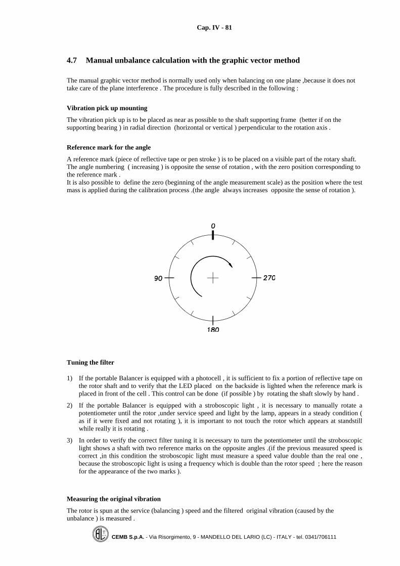
Cap. IV - 81
CEMB S.p.A. - Via Risorgimento, 9 - MANDELLO DEL LARIO (LC) - ITALY - tel. 0341/706111
4.7 Manual unbalance calculation with the graphic vector method
The manual graphic vector method is normally used only when balancing on one plane ,because it does nottake care of the plane interference . The procedure is fully described in the following :
Vibration pick up mounting
The vibration pick up is to be placed as near as possible to the shaft supporting frame (better if on thesupporting bearing ) in radial direction (horizontal or vertical ) perpendicular to the rotation axis .
Reference mark for the angle
A reference mark (piece of reflective tape or pen stroke ) is to be placed on a visible part of the rotary shaft.The angle numbering ( increasing ) is opposite the sense of rotation , with the zero position corresponding tothe reference mark .It is also possible to define the zero (beginning of the angle measurement scale) as the position where the testmass is applied during the calibration process .(the angle always increases opposite the sense of rotation ).
Tuning the filter
1) If the portable Balancer is equipped with a photocell , it is sufficient to fix a portion of reflective tape onthe rotor shaft and to verify that the LED placed on the backside is lighted when the reference mark isplaced in front of the cell . This control can be done (if possible ) by rotating the shaft slowly by hand .
2) If the portable Balancer is equipped with a stroboscopic light , it is necessary to manually rotate apotentiometer until the rotor ,under service speed and light by the lamp, appears in a steady condition (as if it were fixed and not rotating ), it is important to not touch the rotor which appears at standstillwhile really it is rotating .
3) In order to verify the correct filter tuning it is necessary to turn the potentiometer until the stroboscopiclight shows a shaft with two reference marks on the opposite angles .(if the previous measured speed iscorrect ,in this condition the stroboscopic light must measure a speed value double than the real one ,because the stroboscopic light is using a frequency which is double than the rotor speed ; here the reasonfor the appearance of the two marks ).
Measuring the original vibration
The rotor is spun at the service (balancing ) speed and the filtered original vibration (caused by theunbalance ) is measured .

Cap. IV - 82
CEMB S.p.A. - Via Risorgimento, 9 - MANDELLO DEL LARIO (LC) - ITALY - tel. 0341/706111
Measuring the vibration with the test mass applied
A test mass is applied on the balancing plane and the new filtered vibration is measured .
Vibration value
The amount of the filtered vibration (vibration related to the unbalance ) is directly shown by the instrument .
Vibration angle (phase )
When using a vibrometer equipped with a photocell, the angle of the vibration is immediately shown on themachine display.When using a vibrometer equipped with a stroboscopic light ,the angle is seen directly on the rotorsurface(top point ) by the stroboscopic light placed on a fixed position (vertical or horizontal for instance).Before starting the balancing process the angle division is marked directly on the rotor .

Cap. IV - 83
CEMB S.p.A. - Via Risorgimento, 9 - MANDELLO DEL LARIO (LC) - ITALY - tel. 0341/706111
Practical instructions (step by step operations) for manual unbalance calculation
Reference is made to the table reported on the next page , for a rotor having the following features :correction radius R = 1000 mm and mass M = 2000 kg.For a proper unbalance calculation , the measuring instrument should use a filter with a band with lower thanor equal to 5%.
1) Fill the annexed table with:
- Original vibration (value and angle)– New vibration with the added test mass (value and angle)
2) Draw points A and B (see the example).
3) Connect point A to B ,measure the distance A-B and write its value in the pre set position. (Forevaluating this value take care of the used reduction scale ,for instance 1 cm = 10 microns or1 cm = 1 mm/s)
4) Draw a line starting from O parallel to the segment AB from B to A ;this line defines the angle ϕ.
5) Remember to remove the test mass.
6) By using the reported formula , calculate the correction mass (compensating for the existing unbalance )and its angular position .
7) Measure the residual vibration and if it is still not acceptable , proceed with a new balancing operationfollowing the reported procedure
Notes:
1) The calculated angle is for balancing by adding weight ; in case of balancing by removing , the angle isin the opposite position (+180°).
2) When the calculated angle is negative ,add 360° to make it positive.

Cap. IV - 84
CEMB S.p.A. - Via Risorgimento, 9 - MANDELLO DEL LARIO (LC) - ITALY - tel. 0341/706111
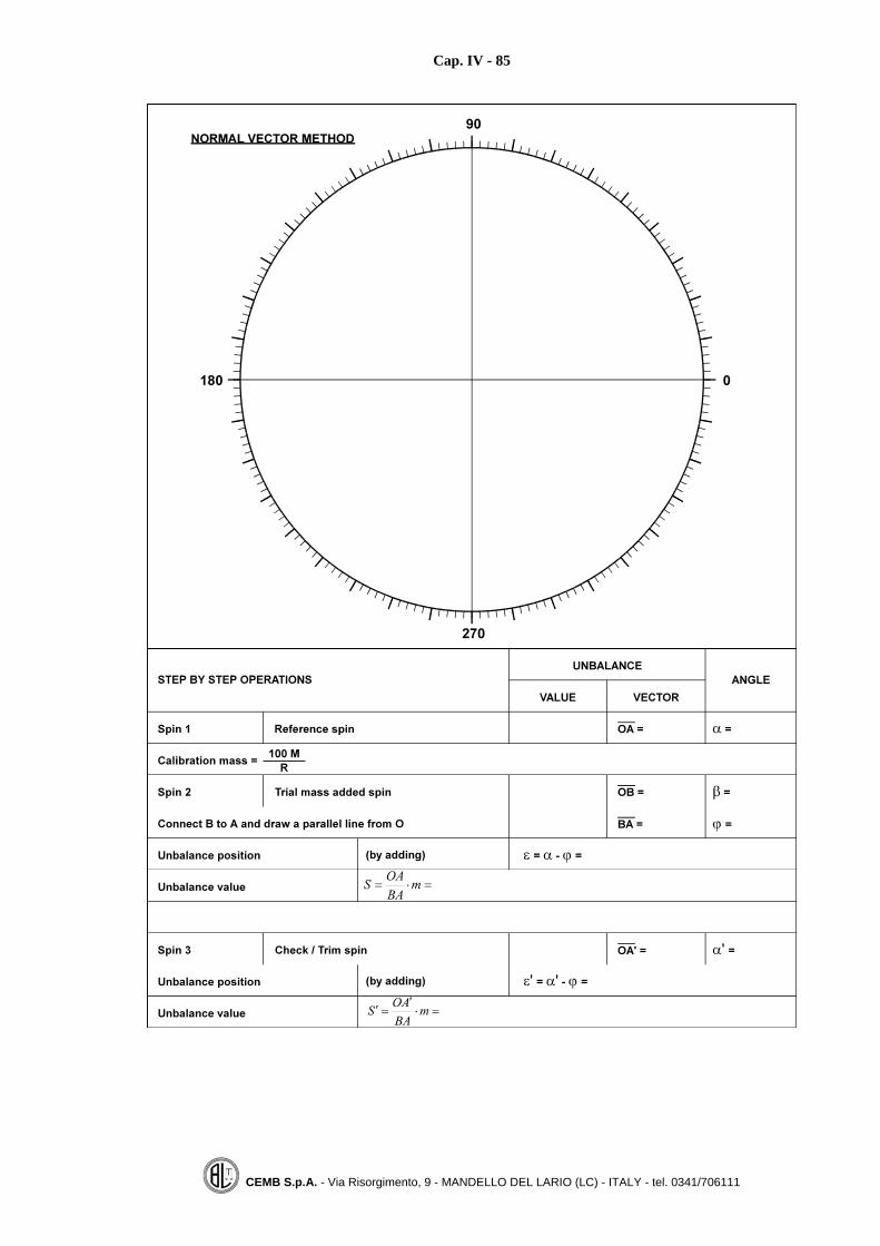
Cap. IV - 85
CEMB S.p.A. - Via Risorgimento, 9 - MANDELLO DEL LARIO (LC) - ITALY - tel. 0341/706111

Cap. IV - 86
CEMB S.p.A. - Via Risorgimento, 9 - MANDELLO DEL LARIO (LC) - ITALY - tel. 0341/731384
4.8 Evaluation of the optimum angle position of the test mass during calibration
High original vibration values (almost dangerous), requirements to reduce the number of balancing spins(electric motors with a reduced number of start up cycles for thermal reasons ) draw the attention to carefullyevaluate the value and angle position of the test mass used during the calibration process .If, during the calibration spin , the test mass is placed on the correct angle (that is in an angle opposite theposition of the original unbalance) the machine bearings are not suffering higher vibration values and thebalancing process is shorter (less spins ).In order to evaluate the best angle position for the test mass different angle addendum are to be considered :
F1: Angle depending on the used measuring unit
Measuring unit Angle F1
DespacementVelocity
Acceleration
0–90-180
F2: Angle depending on the position of the relative position rotor speed (N) and rotor critic speed(Nc )
F2 F2(recommended)
N < Nc 0÷45 45
0,7 Nc N 1,3 Nc 45÷135 90
N Nc 135÷180 135
F3: Angle depending on the relative position of the photocell with regard to the vibration pick up
F3 = Angle between the photocell and the pick up.This angle is positive if the vibration pick up has to be moved in the same sense of rotor rotation in order toreach the photocell (on the contrary it is negative ).For the example drawing F3 = -50°

Cap. IV - 87
CEMB S.p.A. - Via Risorgimento, 9 - MANDELLO DEL LARIO (LC) - ITALY - tel. 0341/731384
The estimated position of the original unbalance is: 3210 FFF +++α=α
where: α is the measured angle of the original synchronous vibration
The test mass is to placed (on the balancing plane ) at the opposite angle: °+α=α + 18000
Notes:
4) The method is valid under the condition that the angle of the original vibration is properly measured
5) If the calculated angle is negative , make it positive by adding 360°.
6) If the calculated angle is bigger than 360° remove 360°.

Cap. IV - 88
CEMB S.p.A. - Via Risorgimento, 9 - MANDELLO DEL LARIO (LC) - ITALY - tel. 0341/731384
Example 1: Rotor service speed lower than the critic speed (N < Nc )
Vibration measuring unit [mm/s]F1 = -90° (measuring unit mm/s)F2 = 45° (under critic speed)F3 = 90° (angle photocell –pick up)α = 65° (measured original vibration
angle)
Optimum angle for the test mass
°=+++−==++++α=α +
290180904590651803210 FFF
Example 2: Rotor service speed bigger the critic speed (N > Nc )
F1 = -90° (measuring unit mm/s)F2 = +135° (over critic speed)F3 = 30° (angle photocell-pick up)α = 306° (measured original vibration angle )
°=++−=α 1630135903060
This is a real case where the original unbalance was on theangle 0
The optimum position for the test mass is :°=+=α + 196180160

Cap. IV - 89
CEMB S.p.A. - Via Risorgimento, 9 - MANDELLO DEL LARIO (LC) - ITALY - tel. 0341/731384
4.9 Manual balancing with the use of a simple vibration meter
When the vibration value ,caused by the unbalance , is relevant (>60% of the total vibration) it is possible tobalance, on service conditions, by the use of a simple vibrometer (having no filtering capacity ) .
a) Four points method
Four points are marked on the rotor balancing surface at 90 degrees .
Vibration values V0 (original vibration ) and VI , VII , VIII , VIV ( vibrations obtained by moving the testmass m on the angle positions I, II, III, IV at 90° on the balancing plane ) are measured .A sine curve (connecting all points ) is then drawn .
The frame rigidity is 2 ⋅−
=m
V VE
max min
The averaged measured value is 4
IVIIIIIIm
VVVVV +++= (it should be equal to V0).
The original unbalance (calculated ) U is E V⋅ 0.The angle position of the unbalance is evaluated from the curve (distance Vmax from point I)
In the example the angle is 26
90 30⋅ °≅ °

Cap. IV - 90
CEMB S.p.A. - Via Risorgimento, 9 - MANDELLO DEL LARIO (LC) - ITALY - tel. 0341/731384
b) Three points method
Vibration values V0 (original vibration ) and VI , VII , VIII (obtained by moving a test mass m on the angleposition I, II, III at 120°on the balancing plane ) are measured.A circumference with radius a V0 is drawn.Points I, II, III at 120 degrees angle position are marked.The measured vibration values are filed in a decreasing order (for instance VIII > VII > VI).With the centre in point III a circumference with radius VIII is drawn.
With the centre in point II a circumference with radius VII is drawnThe two common points of the circumferences define the two possible unbalance positions .A third circumference , with the centre on point I and a radius VI , defines the correction position (in theexample P1).The unbalance angle is defined by the line connecting point P1 to the centre O of the original circumference(direction P1 O).
The unbalance value is: m
O PV
10×
Example: V0 = 4 mm/sVI = 2 mm/sVII = 5 mm/sVIII = 6 mm/s

Cap. V - 91
CEMB S.p.A. - Via Risorgimento, 9 - MANDELLO DEL LARIO (LC) - ITALY - tel. 0341/706111
CHAPTER 5
FLEXIBLE ROTORS BALANCING
5.1 ForewordA professional approach to flexible rotors balancing requires the knowledge of:
1 ) Rotor critic (natural ) speed (at this speed high vibrations occur even in presence of small unbalancesor other causes )2) Rotor bending mode at the critical speed (it is the geometric shape assumed by the rotor running near itscritic speed ).
Let us consider the following example with a shaft having an original unbalance (static type) concentrated inthe middle and compensated by two equal masses placed at its ends .By increasing the rotating speed , the centrifugal forces related to the three concentrated unbalances increasetogether with the inside shear forces and bending couples ; the overhaul frame is still in equilibrium (theexerted forces on the bearing supports is null).
When the rotating speed approaches the rotor first critic speed the shaft bends.The bending causes itself a big unbalance which even more increases the shaft deformation according to thefirst modal bending shape .With bending the rotor mass distribution changes , while the axis of rotation ( defined by the two supportingbearings ) does not change .
If the rotating speed increases again ,over the critic speed value , the shaft shape becomes again straight .

Cap. V - 92
CEMB S.p.A. - Via Risorgimento, 9 - MANDELLO DEL LARIO (LC) - ITALY - tel. 0341/706111
5.2 Shaft critic (natural ) speed evaluation methods
The measurement of the real rotor critic (natural ) speed is very important , because it gives the possibility toevaluate if the rotor ,on the service conditions , is running near its critic speed , that is : it is to be consideredas a rigid or a flexible rotor .
a) Impact test method
By the use of a proper hammer impulse the rotor is exited to vibrate and its natural vibration frequency inCPM (cycles per minutes ) is measured with a vibration transducer .
Natural vibration mode of a frame exited by an impulsive shock
Natural waveform (over the time ) of the transient vibration caused on a shaft byan impulsive shock

Cap. V - 93
CEMB S.p.A. - Via Risorgimento, 9 - MANDELLO DEL LARIO (LC) - ITALY - tel. 0341/706111
b) Bode diagram
It is necessary to use an instrument capable of storing and displaying the synchronous vibration or thedisplacement as a function of the rotor speed .For a paper roll ,for instance , the bending value in the middle is registered ,in value and angle , as a functionof the speed .This way ,the response of the assembly (rotor plus supports ) is measured as a function of the rotarycentrifugal force (caused by the unbalance ) acting on the frame with increasing angular speeds ( at differentfrequencies ).
The following typical diagram is obtained :
Near to the critic speed the vibration level increases a lot and its angle changes by 90° , while above the criticspeed the angle changes by 180°.

Cap. V - 94
CEMB S.p.A. - Via Risorgimento, 9 - MANDELLO DEL LARIO (LC) - ITALY - tel. 0341/706111
5.3 Calculation of the critic (natural ) speedIf the rotor mechanic features such as :
Rigidity K [N/m]Inertia I [m4]Material density [kg/m3]
and the rotor boundary conditions are known , the different rotor natural (critic ) bending frequencies can becalculated by numeric computation .
The finite element method is today commonly used and standard software packages are available to be easilyused on every process computer .
The theoretical calculation of the rotor critic speed is outside the scope of this course ; nevertheless it isimportant to know the next formula which points out the main parameters which contribute to determine thevalue of the first critic speed (every frame has different critic (natural ) speeds , with different relatedvibration shape modes ).
fKMn = ⋅
12π
where:
fn = first critic speed in CPS (cycles per seconds)
K = rigidity [N/m]
M = rotor mass [kg](The frequency in cycles per minutes is obtained by multiplying fn x 60 )From the formula it is clear that the critic speed increases with the rigidity and decreases with the rotor mass .These are the two parameters which are to be changed in order to modify a disturbing critic speed (do notforget that , near to a critic speed , even small unbalances can generate high vibrations or bending ).A formula which calculates the first critic speed of a uniform beam in term of revolutions per minutes is :
sc f
gV ⋅=π2
60
where:g = gravitational acceleration = 9.8 m/s2fs [m] = static bending in the middle section
In the case of a uniform beam simply supported at the ends the centre bending is :
IElgmf s ⋅
⋅⋅⋅=4
3845
where:m = mass per unity of length [kg/m]E = Beam elasticity [N/m2]l = distance between supports [m]
By introducing the value for the centre bending fs into the previous formula we obtain :
m
IEl
Vc⋅
⋅⋅π
= 2
76,8260
[CPM]

Cap. V - 95
CEMB S.p.A. - Via Risorgimento, 9 - MANDELLO DEL LARIO (LC) - ITALY - tel. 0341/706111
5.4 Natural frequencies of a beam calculation
By solving the general differential equation for the lateral vibrations of uniform beams ,the different naturalspeeds ( frequencies ) are calculated by the next formula :
mIEnn⋅
⋅= 2ω (1)
where:ωn = Natural frequency for the n vibration mode [rad/s]
E = Beam elasticity [N/m2]
( for the steel E = 21’000 kg/mm2 2106 N/m1021
1010000'21
×=×
= − )
I = Beam inertia [m4]
m = Mass per unit length [kg/m]( m = ρ A , with A = area [m2] and ρ = mass density [kg/m3] ; for the steel ρ = 7.8 g/cm3 = 7.8·1000 kg/m3)
n2 = Factor depending on the boundary conditions ,on the different natural vibration modes and on the beamlength l [m] according to the next table :
Boundaryconditions
1a speed2
1 )( ln ⋅2a speed
22 )( ln ⋅
3a speed2
3 )( ln ⋅
Simply supported 9.87 39.5 88.9
Cantilever 3.52 22.4 61.7
Double clamp 22.4 61.7 121.0
Clamped/hinged 15.4 50.0 104.0

Cap. V - 96
CEMB S.p.A. - Via Risorgimento, 9 - MANDELLO DEL LARIO (LC) - ITALY - tel. 0341/706111
We develop now the previous formula (1) for a very common case of a paper roll with a ( cylinder )uniform section .
For a simply supported condition at its ends , the fist natural frequency is :
mIE
lV ⋅
⋅⋅π
= 2187,9
260
[CPM]
( The same value with the formula reported on the previous chapter ,based on the static bending in themiddle , is lower of about 10%)
For a uniform (cylinder ) section with D = outside diameter [m] and d = inside diameter [m]:
( )2233
4kg/m108.7[kg/m] dDm −⋅
π⋅⋅=
( )444
64][m dDI −⋅
π=
The first natural speed of a ,simply supported ,uniform steel cylinder beam (roll ) can be calculated with thenext formula :
2221
122263[CPM] dD
lV +⋅=
Calculation example with:
l = 5 mD = 450 mm = 0,45 md = 350 mm = 0,35 m
we get : ogiri/minut27881225,02025,05,489035,045,025
122263 221 =+⋅=+⋅=V
According to the formula of the previous chapter ogiri/minut247676,887,9
27881 =⋅=V
From the comparison of the measured and the calculated values for the first natural speed of uniform steelpaper rolls , simply supported on its end journals ,it seems that this last formula (of the previous chapter )gives better results. It is reported down for an easy use :
2221
110037[CPM] dD
lV +⋅=

Cap. V - 97
CEMB S.p.A. - Via Risorgimento, 9 - MANDELLO DEL LARIO (LC) - ITALY - tel. 0341/706111
5.5 Rotors classification
Depending on its maximum speed a rotor is classified as
Rigid rotor
The maximum service speed is lower of 30% of the first natural bending speed.(that is V< 0,7 Vc where V = maximum service speed and Vc = first natural rotor speed)
It can be dynamically balanced on two arbitrary planes.
It can be balanced at an arbitrary speed ,below or equal to the service speed.
Its masses distribution around the axis of rotation remains constant .
Flexible rotor
The maximum service speed is bigger than the previously specified value ,that is V> 0,7 Vc.
A flexible rotor is to be balanced
a) In well specified planes (sometimes more than two).
b) At special speeds (sometimes at more than one speed ).
Near to the critic speed the rotor mass distribution changes due to the bending .
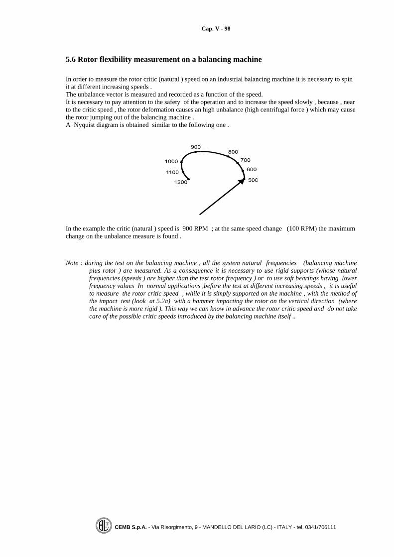
Cap. V - 98
CEMB S.p.A. - Via Risorgimento, 9 - MANDELLO DEL LARIO (LC) - ITALY - tel. 0341/706111
5.6 Rotor flexibility measurement on a balancing machine
In order to measure the rotor critic (natural ) speed on an industrial balancing machine it is necessary to spinit at different increasing speeds .The unbalance vector is measured and recorded as a function of the speed.It is necessary to pay attention to the safety of the operation and to increase the speed slowly , because , nearto the critic speed , the rotor deformation causes an high unbalance (high centrifugal force ) which may causethe rotor jumping out of the balancing machine .A Nyquist diagram is obtained similar to the following one .
In the example the critic (natural ) speed is 900 RPM ; at the same speed change (100 RPM) the maximumchange on the unbalance measure is found .
Note : during the test on the balancing machine , all the system natural frequencies (balancing machineplus rotor ) are measured. As a consequence it is necessary to use rigid supports (whose naturalfrequencies (speeds ) are higher than the test rotor frequency ) or to use soft bearings having lowerfrequency values In normal applications ,before the test at different increasing speeds , it is usefulto measure the rotor critic speed , while it is simply supported on the machine , with the method ofthe impact test (look at 5.2a) with a hammer impacting the rotor on the vertical direction (wherethe machine is more rigid ). This way we can know in advance the rotor critic speed and do not takecare of the possible critic speeds introduced by the balancing machine itself ..

Cap. V - 99
CEMB S.p.A. - Via Risorgimento, 9 - MANDELLO DEL LARIO (LC) - ITALY - tel. 0341/706111
5.7 Basic criteria for flexible rotors balancing
The goal of flexible rotors balancing is to obtain acceptable operating conditions in term of vibration levelsor bearing life , which is possible only if the rotor mass distribution around the axis of rotation does notchange over the all speed range .
To obtain the goal it is necessary to reduce to a minimum the forces inside the rotor (bending moments andshear forces caused by concentrated unbalances along rotor axis ) which increase with the speed and maycause rotor deformations .
Example of a rotor (having an original unbalance concentrated in the middlesection ) and balanced with two masses at its ends .
.
Inside moments diagram ,caused by the rotary forces ,related to the previous example
The bending moment is maximum in the middle and its value is m][N2
22⋅ω⋅⋅
lU
If we balance the rotor section by section ,that is , if we remove any concentrated unbalance ,the insideforces (bending moments and shear forces ) caused by the centrifugal forces are reduced to a minimum andthe rotor is not forced to bend .

Cap. V - 100
CEMB S.p.A. - Via Risorgimento, 9 - MANDELLO DEL LARIO (LC) - ITALY - tel. 0341/706111
Example of rotor divided into different sections individually balanced
The centre of mass of each rotor section lays on the axis of rotation .
By increasing the speed the inside moments caused by the centrifugal forces are reduced to a minimum .
The above mentioned balancing procedure is commonly used in the practise .
Let us mention ,for instance ,the balancing of steam and gas turbines where each blade ring is individuallybalanced (each blade is scaled before mounting it on a ring ) and the balancing operation is repeated at eachring mounting on the shaft (the unbalance correction is made on the ring itself ).
Another example is the balancing of cars turbochargers where the turbine shaft and the compressor areseparately balanced .

Cap. V - 101
CEMB S.p.A. - Via Risorgimento, 9 - MANDELLO DEL LARIO (LC) - ITALY - tel. 0341/706111
5.8 Rotors classification according to balancing requirements
According to ISO standards , for balancing purposes ,all rotors can be classified as :
1) Rigid rotors
2) Quasi rigid rotors
3) Flexible rotors
4) Rigid rotors with flexible or not rigid connections
5) Flexible rotors to be balanced at the service speed only
5.9 Quasi rigid rotors
The maximum service speed is near to the critic speed but they can be balanced at low speed by acting onwell known planes
They are classified as:
1) Rotors with known axial unbalance distribution ( pulley on a flexible shaft, f.i.)
2) Rotors with unknown unbalance distribution ,but in fixed planes (multi stages centrifugal pumps f.i.)
Quasi rigid rotors balancing procedure
1) The separate parts are pre balanced as rigid rotors . The mounting tolerances are kept within specifiedvalues .After assembling , the complete rotor is dynamically balanced again on two or more planes .(The static unbalance correction is distributed on the shaft length while the couple unbalance is correctedat the ends)
2) The separate parts are balanced ,step by step ,during the assembling (sometimes two parts are mountedand balanced at the same time and the correction is made on the two planes defined by the two parts ).The shaft alone is balanced first then a ring is mounted and the balancing is made by acting on the ringitself . (It is evident that ,if the shaft has been previously balanced ,the new unbalance is caused by thenew part that has been lately mounted ). After each mounting , the unbalance compensation is made onthe lately mounted component .
3) The single components ( pre balanced or not ) are assembled on the main shaft and the balancingprocess (on the specified planes ) goes on only if the measured unbalance is below a certain maximumadmitted value . (50% of the static unbalance is corrected on the central plane ).the balancing operationis performed only if the original unbalance is relatively low so that , even balancing on two planes ,theinside moments , caused by the rotary centrifugal forces , are kept within low values . (the rotor is bornwith a reduced unbalance value .)

Cap. V - 102
CEMB S.p.A. - Via Risorgimento, 9 - MANDELLO DEL LARIO (LC) - ITALY - tel. 0341/706111
5.10 Examples of low speed balancing
a) API Standards: Multiple stage pumps
One plane (static ) balancing at each ring mounting step
Two planes (dynamic) balancing at each mounting step (Two impellers aremounted at the same time)
Final balancing (finishing )of the complete assembly ;the static unbalance is corrected on the centrewhile the couple unbalance is corrected at the ends .

Cap. V - 103
CEMB S.p.A. - Via Risorgimento, 9 - MANDELLO DEL LARIO (LC) - ITALY - tel. 0341/706111
b) Paper rolls
In the paper rolls , the original unbalance is mainly static , because it is caused by a different wall thicknesson two opposite angle positions ,all along the shaft.The low balancing speed on the roll ends creates an inside bending moment ,which at a high speed candeform the roll (see 5.7).If the original unbalance (mainly static ) is not too high and the balancing speed is not too near to the firstcritic speed ,it is possible to balance , at low speed , in two ways :
1) Placing the correction masses at 0,22 L.The balancing planes placed at 0,22 L reduce to a minimum the residual inside bending moments caused bythe original uniform distributed unbalance together with the correction masses placed on the two balancingplanes .
2) Correcting 60% of the original static unbalance in the centre of the shaft and correcting then the residualunbalance on two planes at the ends . (The compensation is distributed on three planes in order to reduce toa minimum the inside bending moments caused by the rotary inertia forces .
.
Notes:1) The low speed balancing validity can be verified by increasing the rotor speed , in the balancing machine ,
up to the service speed and by checking that the balancing conditions do not vary (no deformation occur )2) Normally the balancing of paper rolls ,which have a low rigidity ,is to be adjusted and verified at the
service speed .3) It is easy to verify that a roll is rigid by simply measuring ,at its centre position ,the bending value ;if the
dynamic run out (bending ) does not vary with the speed , the roll is balanced at all speeds .
Cap. V - 104
CEMB S.p.A. - Via Risorgimento, 9 - MANDELLO DEL LARIO (LC) - ITALY - tel. 0341/706111
5.11 Flexible rotors
1) The balancing planes are to be selected properly and are more than two (3, 5 etc.).
2) It is better to simulate , on the balancing machine ,the rotor service boundary conditions (supportsrigidity and resting positions )
3) They require the balancing at different speeds (more than one and at high speed ).
Important note :When there is the doubt that a rotor has a service speed near to its first critic speed , it isadvisable to define a third balancing plane in a centre position or in a position where therotor experiences the maximum deformation ., so that a proper balancing ( on more than twoplanes can be achieved )

Cap. V - 105
CEMB S.p.A. - Via Risorgimento, 9 - MANDELLO DEL LARIO (LC) - ITALY - tel. 0341/706111
5.12 Number of balancing planes
Let us consider a paper roll simply supported on its ends ;when spun near its first critic (natural speed ) itbends.The first bending mode assumes the shape reported on the next sketch with zero bending at the ends and witha maximum bending in the centre position .
The balanced conditions obtained at low speed balancing on the ends is no more maintained at high speed(the roll bends ). In order to avoid the bending in the centre position , it is necessary to place a proper massalso on the centre plane .As a consequence ,from the example , it is evident that a proper balancing requires three planes (2 for thelow speed balancing ,one the centre for reducing the bending at high speed).After the balancing , if the rotor speed is increased near to the second rotor critic speed ,the roll bends againand assumes the shape corresponding to the second bending mode ,which is shown on the next sketch.
In order to balance the rotor at the second critic speed ,from the figure it is clear that two more planes arenecessary like planes P4, P5.
The next general formula is valid to establish the number of balancing planes for a rotor running near its Nbinding mode : The number of balancing planes for a flexible rotor are : 2N+1
where N = bending mode (1 = first, 2 = second)
From the above reported examples , it is clear that the optimum balancing plane positions are placed wherethe rotor experiences its maximum bending at the critic speed .

Cap. V - 106
CEMB S.p.A. - Via Risorgimento, 9 - MANDELLO DEL LARIO (LC) - ITALY - tel. 0341/706111
5.13 Modal balancingIt is the balancing method ,for flexible rotors, which takes care of the rotor bending shape (mode ) near to thecritic speed in order to find out the correct balancing planes position and the correct set of the test massescapable of exiting only the bending mode under consideration.Step by step instructions are :
1) Pre balance the rotor at low speed (Rigid balancing on two end planes ; it is necessary in order to spinwith safety at high speed )
2) Increase the speed slowly up to the first critic speed (15 ÷ 30% distance)3) Record value and angle of the instrument measurements ( vector V0 ) (repeatability is to be verified )4) Add a set of testing masses capable of exiting only the first bending mode .( better if the previous
balancing conditions are not destroyed ).Look at following examples .5) Spin the rotor to the same balancing speed (point 2) and record value and angle measured by the
instrument (vector V1 ).6) Calculate the unbalance with the use of the vector method (as reported at chapter 4.3 and shown by the
next sketch)7) Continue the balancing for the second bending shape repeating points 2, 3, 4, 58) Repeat all the balancing procedure for the three balancing speeds :
low speednear to the first critic (natural ) speednear to the second critic rotor speed
(at each balancing speed the previous balancing conditions must not be changed ).
where:V0 = Original measurementV1 = Measurement with the applied test masses set UpV1-V0 = Test masses set effect
The masses set capable to eliminate the original unbalance is : 001
0 VVV
UU p ⋅
−=
Note: It is a vector relationship and the test masses set is composed by different masses placed on differentplanes , as shown on the next page .

Cap. V - 107
CEMB S.p.A. - Via Risorgimento, 9 - MANDELLO DEL LARIO (LC) - ITALY - tel. 0341/706111
5.14 Modal balancing test masses set
A modal test masses set is composed of different masses , placed on different planes , capable of exiting thebending mode under consideration only , as shown on the next examples .
I° bending mode
one mass placed in the centre
this set does not change the previous unbalance
II° bending mode
this set does not change the previous unbalance
Notes:
1) Sometimes ,for safety reasons ,it is necessary to repeat the high speed balancing (at the firstand second critic speed ) at two speeds ,that is at a distance from the critic speed of 30% and thenof 15% .2) The coefficient influence values are automatically calculated by the standard CEMBmeasuring units , and recorded in order to be used for similar rotors ..

Cap. V - 108
CEMB S.p.A. - Via Risorgimento, 9 - MANDELLO DEL LARIO (LC) - ITALY - tel. 0341/706111
5.15 Influence coefficients method
It is a method of general use allowing to balance a rotor at different speeds and on different balancing planes.It is always convenient ,if possible , to place the correction masses where the rotor bending is bigger .
At each balancing speed the measurement values are recorded (amount and angle ) at each support for :Rotor aloneRotor with a test mass placed in sequence on each individual balancing plane .
The matrix of influence coefficients is built and a system of linear equations define a unique solution (set ofmasses on the different balancing planes ) capable to balance the rotor at all the speeds .(The way to built the influence coefficient matrix is similar to the one described in chapter 4 regarding thebalancing in the service conditions )
V K Uijk ijk jk= ⋅∑where K = 1, n = different balancing speeds
Vij = point i vibration caused by the test mass placed on the balancing plane jj = 1, m = number of balancing planesi = 1, k = number of measuring points
Sometimes the equations system has not a unique solution because the number of equations is different fromthe number of unknown unbalances .In this case the system is solved trying to calculate, among all thepossible solutions , the correction masses which:
• make the residual vibrations values as low as possible over the all speed range . (minimum square rootmethod )
• make the residual vibrations values as low as possible at the service speed by accepting a certainvibration level near to the critic speed . This is the case of a standard power steam turbine ; near to theturbine critic speed that is during the start up and the cast down transients a relatively high unbalancevalue is accepted because it lasts only for a short time , while on the operating speed the vibration

Cap. V - 109
CEMB S.p.A. - Via Risorgimento, 9 - MANDELLO DEL LARIO (LC) - ITALY - tel. 0341/706111
5.16 Balancing tolerances for flexible rotors
a) Foreword
The actual true critic (natural ) speed of a rotor varies from one individual rotor to another even of the sametype ,so the unbalance tolerance is to be specified (on well defined planes ) over a speed range containing therotor critic(s) speed(s) and if necessary also on specified speeds where the rotor may be considered as a rigidone .The dynamic behaviour of a rotor changes a lot , even by changing its speed of a few revolutions , when it isrunning near to the critic speed . (a small speed difference can cause high vibration levels change .).The balancing machine supports , or in general the balancing bench , must not introduce any additional criticspeed which can generate fault readings . The used balancing bench must have its critic speed (s) outside themeasuring range or , when this is not possible , the ( known ) supporting balancing bench critic speeds are tobe excluded from the measuring field .The measuring unit must be capable of recording the measured values versus the speed .
Different criteria for specifying the unbalance tolerance for flexible rotors are given ; the best one to be usedis chosen after an experimental confirmation .For some flexible rotors , an additional finishing balancing on service conditions is to be made after thebalancing on an industrial balancing machine .
b) Residual unbalance tolerance specified (in gr.mm) on the two supporting journals(a = c = 0, b = distance between supports)
The tolerance ( in gr·mm ) is specified on the two rotor journal planes(a = c = 0, b = distance between machine supports )It is the most precise method , even if it is not commonly used , because it is difficult to keep the machinecalibration constant over the all balancing speed range containing the rotor critic speed .Normally an acceptable unbalance (in gr.mm ) is specified for the low speed (rigid ) balancing and theacceptable residual unbalance , on all the speed range , including the critic speed , is requested to be lowerthan x times (10÷20 the specified value for the rigid tolerance )
c) Maximum acceptable dynamic load on the supports (in Newton )
A low speed dynamic residual unbalance ( in gr.mm ) is specified , together with the balancing planes .The maximum acceptable value for the rotary inertia force ( in Newton ) is specified on the balancingmachine supports , for all the speed range.Since the piezo electric pick up output is directly proportional to the rotary inertia force , generated by theunbalance ,this method can be easily used .
d) Maximum dynamic run out (bending ) acceptable in one or more rotor sections
Reference is made to a paper roll , simply supported , running near the critic speed .A maximum value for the dynamic run out , in the centre section , is specified over the all speed range .It is evident that the paper roll ,despite being straight , is to be balanced over the all speed range (low speedincluded ) and an acceptable unbalance value is specified on the two balancing planes .
In special cases , only a maximum dynamic run out value is specified ,near the critic speeds , at certainsections , without any requirement for the residual acceptable unbalance .
Cap. V - 110
CEMB S.p.A. - Via Risorgimento, 9 - MANDELLO DEL LARIO (LC) - ITALY - tel. 0341/706111
e) Maximum acceptable machine supports vibration (mm/s)
The accepted tolerance for the unbalance is specified for the rigid conditions (low speed balancing ), and themaximum balancing machine supports vibration is specified for the all the working range (mm/s) .Of course the maximum vibration levels are obtained around the rotor critic speed , which can be different,even for rotors of the same type .This method ca be easily applied on semirigid type machines which use velometers as transducers , underthe condition that the machine itself does not introduce any critical speed , or the machine critical speeds areclearly known ...The acceptable value for the machine support vibration can be directly measured by spinning several rotorshaving good service conditions or by calculating the acceptable vibration on the balancing machinemultiplying the on service vibration by a factor which takes care of the main differences between mchine sand real rotor s support parameters (rigidity and damping ).The disadvantage of this method is that the accepted tolerances are valid only for a certain machine type(frame of the support and rigidity ).

Cap. V - 111
CEMB S.p.A. - Via Risorgimento, 9 - MANDELLO DEL LARIO (LC) - ITALY - tel. 0341/706111
5.17 Flexible shaft bending evaluation (Whirl)Reference is made to the next figure ,where the most important items are pointed out
M is the mass of the centre disc , equal to the mass value of the complete shaft having a specific unbalanceE [μ] = U / MIf the shaft bends, its shape is shown by the previous figure where G is the centre of mass position , S is thegeometric centre of the disc and OS is the bending value R (peak).When the shaft is rotating at the angular speed ω [rad/s] around the axis O, the equation regulating themotion is :
( ) RKERM ⋅=+⋅ω⋅ 2 where K = shaft rigidity [N/m]
Setting MK
n =ω as the shaft natural speed, by modifying the previous formula , we obtain :
ER
n
n ⋅
⎟⎟⎠
⎞⎜⎜⎝
⎛ωω
−
⎟⎟⎠
⎞⎜⎜⎝
⎛ωω
= 2
2
1
Assuming a fixed value for the specific unbalance E [gr⋅mm/kg] , the bending value R is a function of thedistance between the rotation speed and the shaft natural speed .Some values are reported on the next table .
=ωω
n0,5 0,6 0,7 0,8 3
=
⎟⎟⎠
⎞⎜⎜⎝
⎛ωω
−
⎟⎟⎠
⎞⎜⎜⎝
⎛ωω
2
2
1n
n 0,33 0,56 0,96 1,78 -1,125
For values of ω much greater than ωn (shaft speed bigger than its natural speed ) , the bending value R isequal to the shaft eccentricity E ; this means that the shaft bends with the same value as E but on theopposite direction. (negative value = -1)


Cap. VI - 113
CEMB S.p.A. - Via Risorgimento, 9 - MANDELLO DEL LARIO (LC) - ITALY - tel. 0341/706111
CHAPTER 6
THE BALANCING MACHINES
6.1 Industrial balancing machines classificationThe industrial balancing machines are classified according to the measuring system and to other importantfeatures, as reported on the following table .
Balancing machines classification ( according to the measuring system)
NOT ROTATING (GRAVITATIONAL)Only the static unbalance is measured
ROTATING (DYNAMIC)The dynamic unbalance is measured (static plus couple )
Disadvantages
Force measuring(hard bearings)
Soft bearings
Lower measuringaccuracy (sensitivity) Long cycle times
The centrifugal force caused bythe unbalance is directly
measured (permanentcalibration)
Supports vibration(displacement)is measured
Advantages
Big diameters heavy rotors can be balanced withoutany power supply (f.i. helicopter blades, hugeflywheels etc.) Not completely pasted rotors can bebalanced (grinding wheels not yet hardened)
Completelyrigid
(piezo pick up)
Semirigid(electrodynami
c pick up)

Cap. VI - 114
CEMB S.p.A. - Via Risorgimento, 9 - MANDELLO DEL LARIO (LC) - ITALY - tel. 0341/706111
Balancing machine classification according to the working mode.
Axis of rotationOrizontal
Vertical
Balancing speedFixed
Variable
Spinning device
End drive
Belt drive (no external part is added to the rotor during the measure)
Compressed air (for turbochargers)
Electromagnetic fields (X rays sources )
Operation modeManual
Automatic
Balancing method
By removing material (drilling, milling)mostly used for high speed rotors
By adding material (welding, riveting)pls.note that welding can introduce additional unbalance because ofthermal deformations
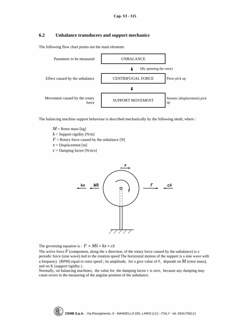
Cap. VI - 115
CEMB S.p.A. - Via Risorgimento, 9 - MANDELLO DEL LARIO (LC) - ITALY - tel. 0341/706111
6.2 Unbalance transducers and support mechanics
The following flow chart points out the main elements
Parameter to be measured UNBALANCE
(By spinning the rotor)
Effect caused by the unbalance CENTRIFUGAL FORCE Piezo pick up
Movement caused by the rotaryforce SUPPORT MOVEMENT Seismic (displacement) pick
up
The balancing machine support behaviour is described mechanically by the following sketh, where :
M = Rotor mass [kg]k = Support rigidity [N/m]F = Rotary force caused by the unbalance [N]x = Displacement [m]c = Damping factor [N/m/s]
The governing equation is : xckxxMF &&& ++=The active force F (component, along the x direction, of the rotary force caused by the unbalance) is aperiodic force (sine wave) tied to the rotation speed The horizontal motion of the support is a sine wave witha frequency (RPM) equal to rotor speed ; its amplitude, for a give value of F, depends on M (rotor mass),and on K (support rigidity ) .Normally, on balancing machines, the value for the damping factor c is zero, because any damping maycause errors in the measuring of the angular position of the unbalance.
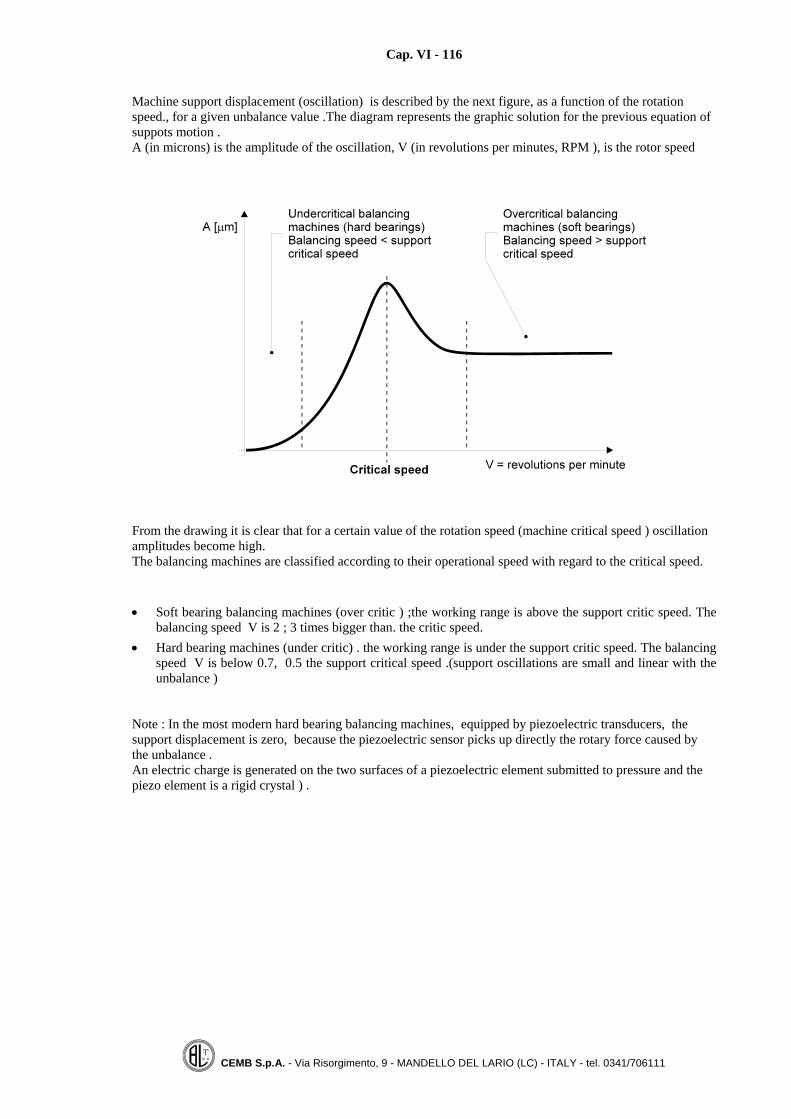
Cap. VI - 116
CEMB S.p.A. - Via Risorgimento, 9 - MANDELLO DEL LARIO (LC) - ITALY - tel. 0341/706111
Machine support displacement (oscillation) is described by the next figure, as a function of the rotationspeed., for a given unbalance value .The diagram represents the graphic solution for the previous equation ofsuppots motion .A (in microns) is the amplitude of the oscillation, V (in revolutions per minutes, RPM ), is the rotor speed
From the drawing it is clear that for a certain value of the rotation speed (machine critical speed ) oscillationamplitudes become high.The balancing machines are classified according to their operational speed with regard to the critical speed.
• Soft bearing balancing machines (over critic ) ;the working range is above the support critic speed. Thebalancing speed V is 2 ; 3 times bigger than. the critic speed.
• Hard bearing machines (under critic) . the working range is under the support critic speed. The balancingspeed V is below 0.7, 0.5 the support critical speed .(support oscillations are small and linear with theunbalance )
Note : In the most modern hard bearing balancing machines, equipped by piezoelectric transducers, thesupport displacement is zero, because the piezoelectric sensor picks up directly the rotary force caused bythe unbalance .An electric charge is generated on the two surfaces of a piezoelectric element submitted to pressure and thepiezo element is a rigid crystal ) .

Cap. VI - 117
CEMB S.p.A. - Via Risorgimento, 9 - MANDELLO DEL LARIO (LC) - ITALY - tel. 0341/706111
6.3 Horizontal axis balancing machine support
The rotary force generated by the unbalance causes a periodic oscillation of the roller cradle supporting rotorjournal.
Note: The hard bearing balancing machines using a velocity transducer (semi rigid machines) havebasically the same type of supporting frame where the oscillating thin plate is replaced by a morerigid plate and the displacement caused by the unbalance is very small(one or two microns). .

Cap. VI - 118
CEMB S.p.A. - Via Risorgimento, 9 - MANDELLO DEL LARIO (LC) - ITALY - tel. 0341/706111
6.4 Horizontal axis hard bearing balancing machine support equipped withpiezoelectric transducers
The rotary force generated by the unbalance causes a sine wave pressure on the piezoelectric crystal, whichreacts with an electric charge having the same oscillation over the time .

Cap. VI - 119
CEMB S.p.A. - Via Risorgimento, 9 - MANDELLO DEL LARIO (LC) - ITALY - tel. 0341/706111
6.5 Vertical axis dynamic balancing machine equipped with piezoelectric pickups.
The next figure shows a vertical axis balancing machine equipped with piezoelectric transducers. The twotransducers (CEMB patent )are placed at 90°. The radial sensor mainly measures the static unbalance, whilethe axial sensor measures the couple unbalance
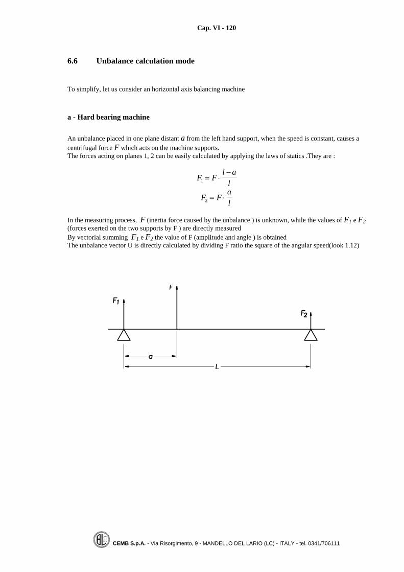
Cap. VI - 120
CEMB S.p.A. - Via Risorgimento, 9 - MANDELLO DEL LARIO (LC) - ITALY - tel. 0341/706111
6.6 Unbalance calculation mode
To simplify, let us consider an horizontal axis balancing machine
a - Hard bearing machine
An unbalance placed in one plane distant a from the left hand support, when the speed is constant, causes acentrifugal force F which acts on the machine supports.The forces acting on planes 1, 2 can be easily calculated by applying the laws of statics .They are :
F Fl a
l1 = ⋅−
F Fal2 = ⋅
In the measuring process, F (inertia force caused by the unbalance ) is unknown, while the values of F1 e F2(forces exerted on the two supports by F ) are directly measuredBy vectorial summing F1 e F2 the value of F (amplitude and angle ) is obtainedThe unbalance vector U is directly calculated by dividing F ratio the square of the angular speed(look 1.12)

Cap. VI - 121
CEMB S.p.A. - Via Risorgimento, 9 - MANDELLO DEL LARIO (LC) - ITALY - tel. 0341/706111
b - Soft bearing machine
Under constant speed conditions the unbalance generates a rotary force which causes aperiodic oscillation onthe two supports 1 e 2.The oscillations X1, X2 of the two supports are related to the axial position of the unbalance (distance a) andto the axial position of the rotor centre of mass (rotor equivalent mass on support 1, 2 )Normally on a rotor, the position of its centre of mass is unknown, so the measure of the oscillations X1,X2 does not immediately gives the value and the axial position of the unbalance (a calibration cycle isnecessary for different rotor types).
For one rotor type, the calibration can be obtained in two ways
1) By the influence coefficient method (look 4.4). Three spins are required . After the first reference spinwith the rotor alone, two additional spins are performed applying a known calibration mass, insequence, on the two balancing planes .The influence coefficient values can be memorized and recalledwhen a similar rotor is to be balanced (in this case the dynamic unbalance is measured at the first spin .)With the rotor mounted and kept in a standstill position, a known unbalance [gr mm] is generated insequence on the two supports. The microprocessor unit directly measures the relationship existingbetween an unbalance, placed in the support plane, and the related support oscillation .
2) The calibration is obtained by placing on machine support a motor having a known unbalance value ; ofcourse the calibrating device is to be smaller compared to the rotor mass. The unbalance , in the twobalancing planes, is then calculated with the same method used for the hard bearing machines

Cap. VI - 122
CEMB S.p.A. - Via Risorgimento, 9 - MANDELLO DEL LARIO (LC) - ITALY - tel. 0341/706111
6.7 Main differences between hard and soft balancing technology
A comparative analysis is given between soft and hard bearing balancing machines with special emphasis tothe practical applications
Features Hard bearing technology Soft bearing technology
1) Permanent calibration Standard. By simply setting upgeometric rotor data, in only onespin, the machine measures theunbalance on both planes (valuesand positions ) and thisindependently of the rotor centre ofmass position.
Three calibration spins are requiredwhen the rotor is mounted the firsttime, at the fist spin the planesseparation and the unbalance valuesare unknown
.
2) Over hang balancing No problem with the use of a simplereverse thrust roller cradle thecomplete rotor can be mounted as itis in the service conditions.
An additional mass or a heavieradapter are used in order to move therotor centre of mass within thesupports .The plane separation ispoor .
.
3) Ventilation effects No problem, it is also possible tobalance at low speed (70 RPM).
The air movement can cause noisingoscillations in the supports. (fanpump turbine impellers ). Thereading can be influenced by anybarrier to the created air flow . Theaxial thrust may create fluctuation (motion)in the thin supporting plates.
4) Flexible rotors balancing No problem if system rigidity(machine supports and foundation )is greater than the rotor critic speed.The machine better simulatesservice conditions .ISO standards forflexible rotor balancing recommendthe use of hard bearing supports
The soft bearings can influence rotorvibration modes . The advantage ofsoft bearings is that they isolate therotors from any noise (critical speed) originated by machine supports andbase .

Cap. VI - 123
CEMB S.p.A. - Via Risorgimento, 9 - MANDELLO DEL LARIO (LC) - ITALY - tel. 0341/706111
Features Hard bearing technology Soft bearing technology
5) High vibration values duringtransients (start and stopping )through the supports critical speed .
No problem It can cause support breaking . Theproblem is overcome by keeping thesupports locked during transients ;they are unlocked when the steadyrunning condition is reached
.
6) High level original unbalances No problem, just reduce thebalancing speed
High vibration which can causesupport damages can be originated .The balancing is impossible, unlessa preliminary gravitationalunbalance (look 1.19) or a prebalancing (locked supports ) aremade .
.
7) Static balancing on a dynamic(two pick ups) machine
The true static unbalance iscalculated and displayed
One support has to be locked, thedisplay is not the true staticunbalance (look 6.8)
8) Foundations Rigid foundations and a goodconcrete floor is required. .Relativelyslow speed is used
Special foundations are not required. The balancing speed is relativelyhigh
.
9) Working environments Suitable to operate in working inworking spaces characterized by :
dust, chips, swarf etc.
cutting forces (drilling thrusts etc.)
The protection against dust or chip isa must , any friction in the pick upmovement can cause a bad reading ..A reaction to every external force isnecessary otherwise the pick ups aredamaged .

Cap. VI - 124
CEMB S.p.A. - Via Risorgimento, 9 - MANDELLO DEL LARIO (LC) - ITALY - tel. 0341/706111
6.8 Error occurring when using a soft bearing machine for static unbalancemeasuring .
Normally people, using a soft bearing balancing machine, when the rotor is to be balanced only in one plane(static), lock the support near to the end drive and reduce the unbalance following the readings coming fromthe free support .the balancing goes on until the support vibration is reduced to zero.This way the rotor is not statically balanced, also the couple unbalance, which contributes to the supportoscillation, is corrected, as shown by the following sketch.
The machine support S1, end drive side is locked, while the other support S2 is free to oscillate Theoscillation of the support S2 is caused by :
• Original static unbalance Us
• Original couple unbalance UcAs consequence the balancing process which takes place following the oscillation of the support S2, even ifobtained by correcting in one plane only, is not a pure static balancing.The error made is greater if:• The original couple unbalance is high.
• The ratio l/d is small
(In order to reduce the error it is necessary to increase the ratio l/d , this way the couple unbalance has alower influence on the oscillation of the free support )
To confirm our theory is simple .After the balancing in one plane only, as described, it is sufficient to verify that the free support does notoscillate even if a couple unbalance is mounted (the display has to measure no variation on the staticreading).This same test can also be performed on a rigid machine and it is recommended by ISO standards 2953.

Cap. VI - 125
CEMB S.p.A. - Via Risorgimento, 9 - MANDELLO DEL LARIO (LC) - ITALY - tel. 0341/706111
6.9 Hard bearing balancing machine proper use
For properly using an hard bearing balancing machine, it is necessary to comply the following items .
a - Rotor mounting
The rotor journals are to be placed directly on the balancing machine rollers in order to grant, on thebalancing unit, the same axis of rotation that the rotor has in the service conditions .If, by any reason, (toavoid journals marking f.i. ) the rotor is not laid on the machine rollers, in correspondence of its bearingposition, it is necessary to verify with a dial that the supporting section is concentric enough with the bearingsection (admitted diameter run out 0.01, 0,02 mm).It is a good rule to avoid the use of couplings placed on the rotor journals .(two possible errors can beintroduced :eccentricity external /internal coupling diameters, eccentricity inside coupling diameter /externaljournal diameter .)
b - Rotor data set up
These data are used to process sensors signals transforming it into unbalance data .With reference to the next figure, it is necessary to set up :
a = distance left support-left left balancing plane (mm)b = distance between left and right balancing planeR1 = left plane balancing radiusR2 = right plane balancing radius
Set up errors causes unbalance measure errors; by setting up, for instance, R1 = 50 instead of 45, themeasured unbalance (in grams ) will be lower of 10%.The values R1 e R2 non do not change the measured unbalance in gr·mm; only an incorrect setting of a, b, cparameters has a negative influence in the unbalance measure . (Be aware that by multiplying a, b, c timesa common constant factor the displayed unbalance value does not change )

Cap. VI - 126
CEMB S.p.A. - Via Risorgimento, 9 - MANDELLO DEL LARIO (LC) - ITALY - tel. 0341/706111
Horizontal axis balancing machine set up parameters
Vertical axis balancing machine set up parameter:
a = upper machine plane – lower balancing plane distanceb = balancing planes distance

Cap. VI - 127
CEMB S.p.A. - Via Risorgimento, 9 - MANDELLO DEL LARIO (LC) - ITALY - tel. 0341/706111
c - Unbalance measuring
The balancing machine measures directly, in one spin, the dynamic unbalance on the two balancing planes :
11,αU and 22 ,αU
where:
U U1 2, = valori di squilibrio in the two balancing planes 1 e 2α α1 2, = posizioni angolari corrispondenti
Following machine readings, by adding or by removing masses, the dynamic unbalance is corrected and therotary forces on the machine supports are reduced to zero .
d - Correction and check spin
After the correction, a check spin is performed in order to verify if the required tolerance has been achieved.
Example of unbalance display in polar form (spot) with value and angle display .The polar display is useful to immediately verify the type of unbalance (static if thetwo spots have the same angular position, couple if the two spots are opposite),nearer is the spot to the centre lower is the unbalance .
In the example, the two unbalances have opposite angular positions .

Cap. VI - 128
CEMB S.p.A. - Via Risorgimento, 9 - MANDELLO DEL LARIO (LC) - ITALY - tel. 0341/706111
6.10 Working range of a variable speed hard bearing balancing machine
The working range of a general purpose, variable speed, hard bearing balancing machine is defined by acurve, which is normally reported in the instruction manual. As a function of rotor weight (vertical axis ) theline shows (on the horizontal axis ) the minimum and maximum usable balancing speed. Within the workingrange the machine is permanently calibrated (maximum error about 10 percent)
• Above the reported maximum balancing speed the machine is no more calibrated.• For balancing values between 0,6 ÷ 0,9 Vmax, the machine has its optimum performances (sensitivity);
for lower values the machine sensitivity decreases• With the use of the self learning mode, if safety allows, CEMB balancing machines can be used above
the speed limit values .
The hard bearings machines Manufacturers normally, instead of the curve, declare a value for Pn2, that isthe product of the rotor mass (in kg ) times the square of the maximum usable balancing speed for that rotormass. The measuring unit for Pn2 is kg·RPM2 where RPM is the maximum balancing speed measured inrevolution per minutes.If, on a balancing machine, the declared value for Pn2 is 700·106 kg·RPM2, it means that a rotor, whosemass is 700 kg,, can be balanced using a maximum balancing speed of 1000 revolution per minutes.The product Pn2 is 700 kg x 10002 = 700·106.A rotor whose mass is 1400 kg can be balanced on the same machine with the maximum speed of1000 / 2 , that is 710 RPM .The value Pn2 is a way to measure machine supports rigidity ; bigger is its value more rigid are machinesupports.

Cap. VI - 129
CEMB S.p.A. - Via Risorgimento, 9 - MANDELLO DEL LARIO (LC) - ITALY - tel. 0341/706111
6.11 Specific calibration balancing on a hard bearing machine (Self learning ofinfluence coefficients)
The hard bearing balancing machines are permanently calibrated because they measure the unbalance in thetwo balancing planes (dynamic unbalance ), in one spin ; it is only necessary to set up the rotor geometricparameters a, b, c (look 6.9). The permanent machine calibration is obtained by the manufacturer whichuses a standard rigid rotor ( ISO test rotor ), with known masses applied to well defined balancing planes .
In many applications when:
• The balancing planes are very near ( narrow planes)• The balancing planes are overhang (outside supports)• It is necessary to balance an assembly (motor and fan together)• The required balancing. speed is outside the machine working range
It happens that the permanent calibration does not permit an ease and satisfactory balancing (the calibrationand the planes separation is not good enough ) .In all these cases a specific calibration for the particular rotor under balancing is possible.The calibration method is similar to the balancing method under service conditions (look 4.5). Thecalibration factors (influence coefficients )can be memorized and recalled for balancing similar rotors ; ofcourse the rotor is to be mounted in the same calibration conditions (mounting conditions and speed ).This method gives to possibility to obtain low values for residual unbalance with a precise machine response,which is not possible using the permanent calibration method unless special mounting adapters are used.
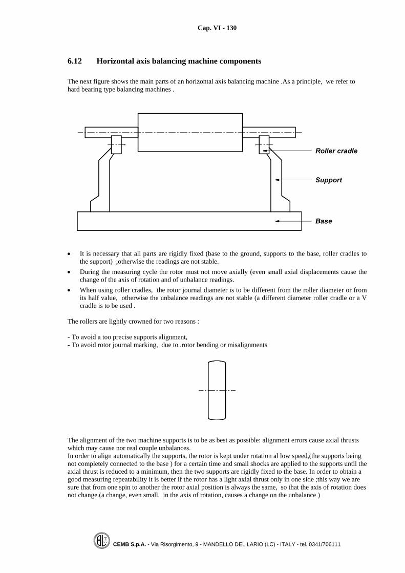
Cap. VI - 130
CEMB S.p.A. - Via Risorgimento, 9 - MANDELLO DEL LARIO (LC) - ITALY - tel. 0341/706111
6.12 Horizontal axis balancing machine components
The next figure shows the main parts of an horizontal axis balancing machine .As a principle, we refer tohard bearing type balancing machines .
• It is necessary that all parts are rigidly fixed (base to the ground, supports to the base, roller cradles tothe support) ;otherwise the readings are not stable.
• During the measuring cycle the rotor must not move axially (even small axial displacements cause thechange of the axis of rotation and of unbalance readings.
• When using roller cradles, the rotor journal diameter is to be different from the roller diameter or fromits half value, otherwise the unbalance readings are not stable (a different diameter roller cradle or a Vcradle is to be used .
The rollers are lightly crowned for two reasons :
- To avoid a too precise supports alignment,- To avoid rotor journal marking, due to .rotor bending or misalignments
The alignment of the two machine supports is to be as best as possible: alignment errors cause axial thrustswhich may cause nor real couple unbalances.In order to align automatically the supports, the rotor is kept under rotation al low speed,(the supports beingnot completely connected to the base ) for a certain time and small shocks are applied to the supports until theaxial thrust is reduced to a minimum, then the two supports are rigidly fixed to the base. In order to obtain agood measuring repeatability it is better if the rotor has a light axial thrust only in one side ;this way we aresure that from one spin to another the rotor axial position is always the same, so that the axis of rotation doesnot change.(a change, even small, in the axis of rotation, causes a change on the unbalance )

Cap. VI - 131
CEMB S.p.A. - Via Risorgimento, 9 - MANDELLO DEL LARIO (LC) - ITALY - tel. 0341/706111
6.13 Different types of cradles used for rotors balancing
During unbalance measuring, the rotors are laid on supporting frames (cradles 9 of different types
Normal rollers cradle: it isused to balance rotors on itsjournal, when the rotorcentre of mass is within thetwo supports. The two rollsare crown and its diametereccentricity, should be below.01mm.
Rollers diameter is to bedifferent from the journaldiameter
pr φ≠φ2
pr
φ≠φ
Reverse thrust roller cradle; it is used, on one supportside, to balance rotors whosecentre of mass is out boardthe opposite support.,(avertical force is generated )the contact rotor journal /upper rollers is to be constantand stable(constant loadupwards).
Over hang roller cradle ; itis used to balance specialelectric motors having insidejournals .

Cap. VI - 132
CEMB S.p.A. - Via Risorgimento, 9 - MANDELLO DEL LARIO (LC) - ITALY - tel. 0341/706111
V flat cradle ;it is used to balance a rotor complete with its own bearings . It is advisable to use a relativelyhigh speed (1400 ÷ 2500 CPM) so that the ball s bearing can reach the same position they have under serviceconditions .
Self aligning V cradle: it has the same use as the previous cradle, with the advantage of permitting rotoralignment during balancing .
Sleeve bearing cradle: it is used to balance very heavy rotors (turbines, armatures etc.) having soft journal ;the risk of marking is eliminated because the rotor supporting surface is bigger and the local pressure isreduced.

Cap. VI - 133
CEMB S.p.A. - Via Risorgimento, 9 - MANDELLO DEL LARIO (LC) - ITALY - tel. 0341/706111
End flanged cradles ; they are used to balance cardanic shafts .They reproduce, in the balancing machine,the same mounting conditions the propeller shafts have in its service conditions. Sometimes, the inside partof the cradle is axially movable in order to facilitate the mounting of the shaft . The two end flanged cradlesmust be perfectly aligned., otherwise an axial thrust can be generated with a anoice on unbalance measuring .
Antifriction material V cradles: they are used for:– Balancing small armatures– Balancing small crankshafts (the risk of journal marking, because of the lubrication hole is reduced )A system for static electricity discharging , is required.


Cap. VII - 135
CEMB S.p.A. - Via Risorgimento, 9 - MANDELLO DEL LARIO (LC) - ITALY - tel. 0341/706111
CHAPTER 7
BALANCING METHODS
FOR MOST COMMON PRACTICAL CASES
The balancing methods for some common rotor types are briefly reported on the next pages, together with anexplanation of the basic concepts.

Cap. VII - 136
CEMB S.p.A. - Via Risorgimento, 9 - MANDELLO DEL LARIO (LC) - ITALY - tel. 0341/706111
7.1 Crankshafts
They are , in the most of cases , balanced by drilling or milling on the webs and can be classified into twocategories .
a) Crankshafts classification
I° category
All the cranks having its mass (pistons included ) evenly distributed around the axis of rotation belong to thefirst category (the axis of inertia is equal to the axis of rotation ) .The reciprocating forces of the first order ,caused by the pistons acceleration are self balanced . They can be directly mounted an a balancing machineas a common rotor .
II° category
The mass is not evenly distributed around the axis of rotation. The reciprocating forces caused by the pistonsmotion are not balanced For this types of rotors the balancing on a machine is only an acceptablecompromise , because a rotating force ( like the one originated by the unbalance associated with a web )cannot counterbalance a reciprocating force ( like the one originated by the pistons ) acting on one planeonly . Proper masses (Bob weights ) , are to be applied to the shaft cranks ,before mounting the crankshafton the balancing machine .
A crankshaft belongs to category I° if the two following conditions are verified :
1) The mass is simmetrically distributed around the axis of rotation ( = axis of rotation )
2) There is an axial simmetry of the masses around an axis perpendicular to the axis of rotation andpassing through the centre point

Cap. VII - 137
CEMB S.p.A. - Via Risorgimento, 9 - MANDELLO DEL LARIO (LC) - ITALY - tel. 0341/706111
b) Balancing speedThe balancing speed should be not too high in order to avoid that the shaft itself could bend because of itsweight or because of the local rotating forces caused by the concentrated unbalances (web masses ). Theright balancing speed is simply verified by measuring the unbalance at different speeds ( ± 100 RPM ) ; themeasured values should be the same in order to confirm that the shaft keeps rigid (in the case , the balancingspeed is to be reduced ).The balancing conditions shall reproduce the service conditions.Note: under service conditions the shaft is surely rigid because it is supported on all its journals , while on thebalancing machine it is supported only on two positions and is subject to bending because of its weight orbecause of the high rotating forces caused by its webs .
c) Balance qualityFor agricultural tractors or trucks crankshafts the required quality is G = 40.according to ISO Standards.The most used quality is G = 16.Only for shafts belonging to the first category sometimes quality 6,3.is requested .
d) Bob weightsThe compensation masses , which simulate the piston masses , for the shafts belonging to the II° category ,(tobe applied to each crank during the balancing process ) are calculated in order to compensate 100% therotating mass (connecting rod big end ) and 50% the reciprocating mass (piston ) by using the followingformula .The value 0.5 is a compromise ; for some application a different factor comprised between 0.4 and0.6 is used .
m m mr a= + 0 5,where:
=m compensating mass value (bob weight or bush )=rm part of the connecting rod having mainly a rotary movement (about 2/3 of rod mass)
ma = piston + pin and segments + connecting rod small end (about 1/3 of rod mass )0,5 = compensation factor for the reciprocating mass (this value is comprised , depending on the
motor boundary conditions on the two radial axis , between 0,4 and 0,65)
Bob weights shall have an equal mass (maximum admitted mass difference below 1/10 the admitted residualunbalance ) , shall be balanced and perfectly centered on the crank journal .It is to be pointed out that , in the case of crankshafts belonging to the II° category, the balancing is acompromise ; a rotary force caused by the concentrated web unbalance is used to compensate the pistonreciprocating inertia force .Without any piston compensation (no webs on the cranks) a reciprocating force , acting on the vertical plane ,is generated by the piston , while with a compensation at 100% (compensation factor equal to 1 ), the verticalforce is cancelled and a new horizontal force is generated ;the compromise of 50% (compensation factorequal to 0.5 ) the vertical force is reduced by 50% while a same reduced force is generated on the horizontaldirection .The only way to compensate a vertical force is to use two unbalanced counter rotating shafts , thetwo counter rotating centrifugal forces generate a force acting only on the vertical plane opposite to thereciprocating force caused by the piston .
Counter rotating masses
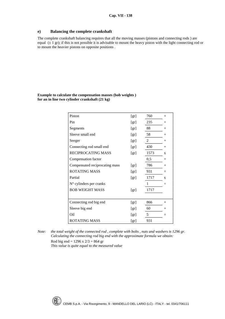
Cap. VII - 138
CEMB S.p.A. - Via Risorgimento, 9 - MANDELLO DEL LARIO (LC) - ITALY - tel. 0341/706111
e) Balancing the complete crankshaftThe complete crankshaft balancing requires that all the moving masses (pistons and connecting rods ) areequal (± 1 gr); if this is not possible it is advisable to mount the heavy piston with the light connecting rod orto mount the heavier pistons on opposite positions .
Example to calculate the compensation masses (bob weights )for an in line two cylinder crankshaft (21 kg)
Piston [gr] 760 +Pin [gr] 235 +Segments [gr] 88 +Sleeve small end [gr] 58 +Seeger [gr] 2 +Connecting rod small end [gr] 430 =RECIPROCATING MASS [gr] 1573 xCompensation factor 0,5 =Compensated reciprocating mass [gr] 786 +ROTATING MASS [gr] 931 =Partial [gr] 1717 xN° cylinders per cranks 1 =BOB WEIGHT MASS [gr] 1717
Connecting rod big end [gr] 866 +Sleeve big end [gr] 60 +Oil [gr] 5 =ROTATING MASS [gr] 931
Note: the total weight of the connected rod , complete with bolts , nuts and washers is 1296 gr.Calculating the connecting rod big end with the approximate formula we obtain:Rod big end = 1296 x 2/3 = 864 grThis value is quite equal to the measured value

Cap. VII - 139
CEMB S.p.A. - Via Risorgimento, 9 - MANDELLO DEL LARIO (LC) - ITALY - tel. 0341/706111
Example drawings for bob weights(compensation masses )
Two pieces cylindrical compensation masses Diameters D and d must beconcentric .
Adjustable weight compensation masses with V shaped locking .

Cap. VII - 140
CEMB S.p.A. - Via Risorgimento, 9 - MANDELLO DEL LARIO (LC) - ITALY - tel. 0341/706111
Quick locking /unlocking compensation mass (bob weight ) .
Method for measuring the connecting rod reciprocating and rotating mass
The rod reciprocating mass m m ma b r= −where : mass rod total=bm mr = massa rotante

Cap. VII - 141
CEMB S.p.A. - Via Risorgimento, 9 - MANDELLO DEL LARIO (LC) - ITALY - tel. 0341/706111
7.2 Propeller shaftsThe balancing of propeller shafts is greatly influenced by the clearances of the existing flexible joints , whichreduce the obtainable precision and sometimes make it impossible .If particularly long and thin , they can be assimilated to rigid rotors .The balancing speed is to be high enough in order to reduce the noise caused by the flexible joints and tosimulate ,on the balancing machine , the service shaft radial position (values of 1000 ÷ 1500 CPM arerecommended for truck shafts and values of 2000 ÷ 3000 CPM for car shafts ).A way to verify the right balancing speed is to measure the unbalance at different speeds ( ± 200 / 300 RPM),the measured unbalance should not vary .The unbalance compensation is obtained by welding small steel plates near shaft ends . Spot welding orprojecting welding are the most used correction methods ; for the last system special steel plates having 2 or3 protuding parts are used , as shown on the following sketch .
The small steel plates are welded on the connecting tube , near shaft ends , and on a centre position if theshaft is bending .The use of a special cradle simulating on service conditions is necessary to mount the shaft on the balancingmachine (look at next figure and at paragraph 6.13).Required balancing quality Q is 16 according to ISO Standards (see Chapter 2); it makes no sense to ask fora better accuracy which is not obtainable because of the mechanic clearances of the joints .The propeller shaft connection to the machine D cradle requires the use of an intermediate mounting flange .The achievable balancing results greatly depend on the centring accuracy obtainable by the two intermediateflanges Before locking the intermediate mounting flanges , it is necessary to verify , with a dial , that the twoflanges are perfectly centred and its surface are perpendicular to the axis of rotation (maximum admitted runout equal to 10 microns ) .With a modern machine , equipped with the eccentricity compensation software(see 3.6) the errors introduced by the mounting flanges can be completely eliminated .

Cap. VII - 142
CEMB S.p.A. - Via Risorgimento, 9 - MANDELLO DEL LARIO (LC) - ITALY - tel. 0341/706111
Examples of mounting a propeller shaft on a balancing machine
One piece shaft by using two D cradles
Two pieces shafts by using two roller cradles and one D cradle
Two pieces shafts by using two D cradles and one roller cradle

Cap. VII - 143
CEMB S.p.A. - Via Risorgimento, 9 - MANDELLO DEL LARIO (LC) - ITALY - tel. 0341/706111
7.3 Propeller shaft body balancing (No flexible joints)
The balancing of connecting shafts (pls. refer to the following sketch ) is not easy and several points are to beconsidered .
a) Axis of rotationThe same on service axis of rotation is to be generated on the balancing machine .A machined centring surface is not available for proper mounting on the balancing machine and the axis ofrotation is only determined by the holes on the two external coupling flanges .
b) Shaft mounting on the balancing machineSince resting journals are not available , auxiliary adapters are to be used in order to mount the shafts on thebalancing machine.
b).1 Using standard roller cradlesTwo flanges complete with journals are bolted to each shaft ends (they can also be connected by a centrebody ). The two flange type adapters are to be balanced and perfectly centred by the use of calibrated bolts .(It is advisable to use the software for compensating mounting tool errors ,see 3.6.)
b).2 Using special flanged D cradlesThe two connecting shaft end faces may be not perfectly parallel and not perpendicular to the axis of rotation: so , by using rigid coupling flanges to connect it to the machine D cradles , an axial thrust can be generatedbetween machine supports .This axial thrust can cause the measuring of a not real couple unbalance . It isadvisable to use flexible type coupling flanges between the connecting shaft and machine D type cradle . (asan example look at the following sketch ).
Intermediate coupling flexible type flange (steel for springs width about. 2-4 mm)

Cap. VII - 144
CEMB S.p.A. - Via Risorgimento, 9 - MANDELLO DEL LARIO (LC) - ITALY - tel. 0341/706111
7.4 Fan impellers
• They are normally balanced by adding masses (by welding small steel plates ).• In order to avoid fan deformation caused by the welding process , the compensation masses are fixed by
rivets (the fan is drilled in the correction position ).• Small fan impellers are balanced by adding small clips .• The balancing speed is normally low in order to avoid any air effect or axial thrust on the machine
supports .• In order to eliminate the ventilation effect , the impeller can be spun in the opposide sense of rotation or
can be covered by a wide tape on its radial surface .• Required balancing tolerance corresponds to G 6,3.• When balancing small impellers mounted on car conditioning systems ( radial or axial ),it is advisable to
balance the complete assembly motor plus fun .( this way the mounting coupling errors are completelycorrected ).
• A standard horizontal balancing machine can be used ; for mass production a vertical axis machine isbetter because of the easier and quicker mounting and desmounting .
• If possible it is better to balance the impeller complete with its own shaft .(no errors are introduced bythe mounting adapter )
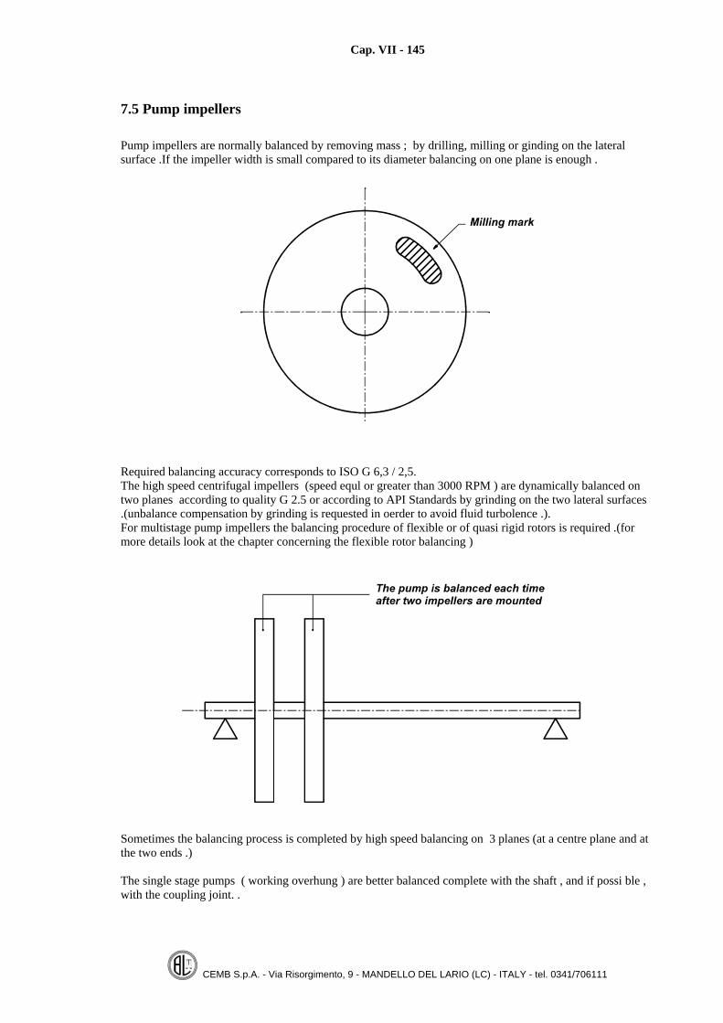
Cap. VII - 145
CEMB S.p.A. - Via Risorgimento, 9 - MANDELLO DEL LARIO (LC) - ITALY - tel. 0341/706111
7.5 Pump impellers
Pump impellers are normally balanced by removing mass ; by drilling, milling or ginding on the lateralsurface .If the impeller width is small compared to its diameter balancing on one plane is enough .
Required balancing accuracy corresponds to ISO G 6,3 / 2,5.The high speed centrifugal impellers (speed equl or greater than 3000 RPM ) are dynamically balanced ontwo planes according to quality G 2.5 or according to API Standards by grinding on the two lateral surfaces.(unbalance compensation by grinding is requested in oerder to avoid fluid turbolence .).For multistage pump impellers the balancing procedure of flexible or of quasi rigid rotors is required .(formore details look at the chapter concerning the flexible rotor balancing )
Sometimes the balancing process is completed by high speed balancing on 3 planes (at a centre plane and atthe two ends .)
The single stage pumps ( working overhung ) are better balanced complete with the shaft , and if possi ble ,with the coupling joint. .

Cap. VII - 146
CEMB S.p.A. - Via Risorgimento, 9 - MANDELLO DEL LARIO (LC) - ITALY - tel. 0341/706111
7.6 Paper rolls
The balancing of paper rolls have two goals:
To reduce the rotating forces ( caused by the unbalance ) on the supporting bearingsTo keep the roll straight (on the contrary there is the possibility to brake the paper )
a) Number of balancing planesNormally paper roll unbalance is caused by a different wall thickness between two opposite lines of the tube, this results as an uniformely distributed unbalance . Almost all paper rolls , even if working away from thenatural frequency , are elastic and because of the relatively high original unbalance , with the speed increasebend ; as a consequense the balancing planes are :2 planes placed at 0,22 l (with l = roll length);3 planes, the two end planes and a centre third plane .Only the rigid rolls (presses) are balanced on the two end planes .
b) Balancing speedThe working speed of a paper roll is variable and it is elastic ; the consequence is that the balancingconditions shall be verified on all the working range , up to the maximum service speed . The paper roll isbalanced at a speed compatible with the machine Pn2 value (relatively low speed ) , then the speed isincreased up to the maximum service speed and the bending value is recorded .(if the dynamic run out orbending does not increase with the speed it means that the balancing conditions do not change ).The use of a bending (run out ) device makes it possible to balance a paper roll at high speed with a machinenot eccessively rigid (low Pn2 value) and has the advantage of directly measuring the paper roll dynamic runout which is a parameter today required.
c) Paper rolls classificationThe following table classifies paper rolls according to the required balancing specifications
Number of balancingplanes
Dynamic run outmeasurement
RIGID ROLLS (PRESSES) 2 NO
Length Max.serviceSpeed
less than1000 m/min 2 YES
less than5 meters Greater than
1000 m/min 3 YES
FLE
XIB
LE
RO
LL
S
Greater than5 meters whichever 3 YES

Cap. VII - 147
CEMB S.p.A. - Via Risorgimento, 9 - MANDELLO DEL LARIO (LC) - ITALY - tel. 0341/706111
d) Unbalance toleranceThe required balancing tolerance for new paper rolls corresponds to ISO 2.5.For reconditioned rolls quality G = 6.3.is required .The next formula calculates quickly the acceptable residual unbalance (quality 2.5) as a function of the mainroll data and of its maximum service speed which is , in the most of cases , specified in meters per minute .
wheree:
2,1U = Admitted unbalance [gr] referred to the roll inside radius
eD = Roll external diameter [mm]
iD = Roll inside diameter [mm]
P = Roll weight [kg]V = Maximum service roll speed [m/min]
The accepted bending value (Dynamic Run out) is also calculated by using the same ISO formula whichdefines the residual acceptable rotor eccentricity as a function of the max. service speed .For quality grade G = 2.5 , the acceptable bending value at the roll centre position is calculated by the nextformula :
VDE e⋅=150
where:E = Acceptable dynamic run out ( in microns ) in the centre position (peak to peak value)
eD = Outside diameter [mm]
V = Max service speed [m/min]
If the calculated value for E is lower than 40 µm ,the value= 40 µm is given to E.
The accepted value for the static bending (mechanic run out or roll straightness ) is about 100 µm.The roll is considered as balanceable if the total measured unbalance is lower than 1/100its total weight .

Cap. VII - 148
CEMB S.p.A. - Via Risorgimento, 9 - MANDELLO DEL LARIO (LC) - ITALY - tel. 0341/706111
e) Flexible rolls balancing procedure
Important notes1) Particular attention is to be paid when fixing masses on the outside diameter and increasing the
speed ..2) When a big original static unbalance is present it is convenient to reduce it by machining the roll
journals out of centre . The eccentricity value can be calculated with the next formula
MUE = where: U = measured unbalance [gr·mm], M = roll mass [kg], E = radial eccentricity
[µm].3) When the roll wall thickness is not within the specified values (big difference on two opposite angle
positions ), it is convenient to remachine the inside diameter in order to obtauin a more uniforthickness .
4) Before measuring the unbalance , keep the rotor running for some time in order to eliminate anystatic bending ..
e).1 Two planes balancing1) Define the two balancing planes at 0,22 l.2) Pre balance at low speed (200 – 300) the roll by fixing masses on the outside diameter with a standing
rope.3) Increase the speed and , at each step correct the unbalance always in the same planes ..4) When the speed is over the machine admitted Pn2 value , the bending measuring pick up is to be used ,
always acting on the same planes and using ropes to fix the provition al compensation masses .5) Continue the balancing process up to the service speed untill both the unbalance (below machine Pn2
value ),both the dynamic run out (on all the roll working range ) are within the specified tolerances .6) Remove the outside provisional correcting masses and apply it on the inside by increasing the value
inthe ratio outside/inside diameters .
e).2 Three planes balancing1) Select the three balancing planes ; two at the end sides as near as possible to the journals and the third
one at the roll centre position .2) Pre-balance provisionally , on roll ends ,at low speed (200 – 300 RPM).3) Spin , at the same low speed , and measure the geometric run out . Record this value and remove it
(subtract ) electronically in order to measure only the dynamic run out .4) Increase the speed , as much as possible with regard to a safety operation ,until the monitored dynamic
run out increases to an unacceptable value ..5) Measure and record the dynamic run out .6) A known test mass is fixed , by using standing ropes on the outside diameter , at the centre roll position
at an angle opposide the measured run out angle . The test mass value can be equal to 40% or 60% themasses used to pre balance at low speed (point 2 ).
7) Spin the roll at the same previous speed ,measure and record the new dynamic run out .The mass to beadded , at the roll centre position , in order to compensate the original bending (dynamic run outmeasured at point 3 ) is calculated with the vectorial method described under paragraph 4.3. Normallythe machine software calculates the correcting mass (value and position )to be applied in the centreposition .
8) Remove the provisional test mass and add the calculated mass on the outside diameter by using standingropes .
9) Measure the unbalance and correct it on the two end planes at low speed (the firstly applied masses arenormally reduced )
10) Repeat steps 3-9 untill the following conditions are obtained :– Residual unbalance on the end planes at low speed or at the maximum balancing speed permitted bythe machine Pn2 (see 6.10) is below the accepted tolerance .– The dynamic run out is within the accepted tolerance on all the service speed range .

Cap. VII - 149
CEMB S.p.A. - Via Risorgimento, 9 - MANDELLO DEL LARIO (LC) - ITALY - tel. 0341/706111
f) Fixing the inside correcting masses
Reference is made to the next figure.
1) Calculate the length of the correctingsteel rod according to the measuredunbalance value and to the inside radius.It is inserted through the holes of rollends .
2) It is advisable to use square or rectangularshaped rod 40x50 mm.max.
3) If the calculated length is longer than800 mm ,some 4 mm. Depth notch is tobe made on the rod length .
4) By using the real correcting rod placed onthe external surface ,mark the position ofthe fixing bolts .the distance between eachbolt is about 200 and 300 mm.
5) Drill and countersink the roll wall ,taking care to prevent chips entering inside .6) Insert the correcting rod and position its threaded holes in correspondence of the roll wall threaded holes
.(to facilitate the operation the roll is supported at its ends and the threaded holes are moved in the lowerposition ).
7) Fix the rod to the roll wall with at least two threaded bolts.8) Rotate the roll in order to move the threaded holes to the upper position .9) Apply LOCTITE on the bolts and screw untill its core is broken .10) Reduce the protuding part , upset ,shape and tape grind it .
Note: Do not weld the bolts to the roll wall..
g) Semicritic speed
When the paper roll is rotating , on a balancing machine ,at a speed equal to the middle of its natural speed ,sometimes high vibrations are measured (high dynamic run out values at the centre ).These vibrations have afrequency double the rotating speed , cannot be reduced by adding masses ( balancing ).and disappear bychanging the rotation speed ( increasing or decreasing it )The explanation of the experience is simple : it is sufficient to consider that a misallignment (caused bymachine supports, rotor journals, support roller cradles ) or out of round rotor journals can generate avibration having a frequency double the running speed . If the running speed is exactly equal to half the rollnatural speed, a small source of vibration (at double frequency ) equal to the roll natural speed ( resonanceconditions ) can excite big vibrations . Paper rolls damping factors are very low ,this explaines why lowimpulses can cause high vibrations .Some rolls manufacturers specify a limit to the bending value in semicritic conditions (2° order dynamic runout ) between 700 and 1400 microns. According to our opinition there is not a direct relationship , whenrunning in semicritic conditions , between paper roll behaviour on the balancing machine and on serviceconditions , because the boundary and damping conditions are different .

Cap. VII - 150
CEMB S.p.A. - Via Risorgimento, 9 - MANDELLO DEL LARIO (LC) - ITALY - tel. 0341/706111
7.7 Vehicle turbo chargers
The Manufacturer balances ,as separate, the turbine shaft and the compressor , as shown on the followingsketch.
People repairing the turboshaft normally balance the complete shaft only by removing material on planes 1and 2 because the single parts have alkready been balance separately .When the measured unbalance values are too high ,it is advisable to verify the mechanicsin order to avoid toremove too much material and , as a consequence ,to compromise the mechanic safety .of the turboshaft .The balancing speed depends on the rotor weight and on the type of the used machine type and generally iscomprised between 2000 and 40000..The balancing tolerance is established by the Manufacturer and varies from type to type depending on theweight and service speed (the computation formulae used for rigid rotors are not applicable ,specially forhigh speed compressors ).As reference value then ,consider that on a Garret turbine type TO1 (totol weight approx 100 grams andservice speed of about 120000 CPM) it is requested to rech on plane 1 and 2 a tolerance of 0.25 gr.mm
In case of small turbochargers running at very high speed (requested tolerance lower than 0.5 gr.mm )it maybe necessary to balance the complete assembly .The compressor mounting/desmounting operation maydamage the requested tolerance ,due to the fact that there may be a non repeatable mechanic centering.In caseof desmounting ,after balancing , it is suggested to make a reference mark so as to minimize the remountingerrors .
The next table lists the required tolerance for different turbine models.

Cap. VII - 151
CEMB S.p.A. - Via Risorgimento, 9 - MANDELLO DEL LARIO (LC) - ITALY - tel. 0341/706111
Required unbalance tolerance for the most common car turbo shafts
COMPRESSOR TURBINETURBOSHAFT MODEL Unit( gr·mm)3LD, 3LDZ 2,1 1,53LKZ, 3LEP, 3LEZ 3LKS 2,1 1,53LKU, 3LEU, 3LKY 2,1 1,53HD, 3HF, 3DB 4,3 3,14LE, 4LF, 4LG, 4LB, 4LGZ, K361 4,3 3,14HD, 4HE, 4MF, 4B, 4BD 4,3 3,1
HO
LSE
T
5MD, 5MDE, 5MDZ, 5MDY 8,0 6,0K14, K16 0,55 0,4K24 1,2 0,9K26 1,3 1,0K27 1,5 1,1K28 1,6 1,2K33 3,7 2,9K34 4,0 3,1K36 4,0 3,1K37 4,6 3,6K42 8,9 7,1K44 9,8 7,8K52 12,3 9,5
KK
K
K54 13,5 10,5T31 0,25 0,38T04, T04B, T04S, TA35 0,25 0,35T05B, TE06 0,51 0,64T06, T07 0,25 0,48TH08A 0,86 1,40T11 0,38 0,84T14 1,27 2,18T18 1,42 1,40T18A 1,37 1,40T30 1,63 2,41T60, TV60, TV61 0,51 0,54TV70, TV71 0,61 0,89TV77 0,61 0,64TV80, TV81, TV91 0,92 1,40
GA
RR
ET
T
TA45, TA54, TM51, TM54 0,51 0,64 / 0,76

Cap. VII - 152
CEMB S.p.A. - Via Risorgimento, 9 - MANDELLO DEL LARIO (LC) - ITALY - tel. 0341/706111
7.8 Hydraulic couplingsThe balancing problem in hydraulic couplings is tied to its geometric shape ; if it is not uniform when thecoupling is filled up by the oil an unbalance is generated .; another point to consider is that the two partscomposing the coupling may work with different relative angle positions .If the geometric shape is good a dry balancing (no oil in ) is enough , the same unbalance is measured withand without the oil .On the contrary the balancing is complicated if the coupling shall work with different oil levels ( the oil levelcontrols the transmitted torque ) ,in this last case the following procedure can give good balancing results .
Balancing procedure1) Balance the coupling in dry conditions by using one or two auxiliary flanges (the measured unbalance is
compensated on the two flanges ).2) Fill up the coupling with different oil levels .At each level perform the balancing acting on decreasing
diameters of the coupling . This way every single coupling ring is balanced when filled up with the oil .3) Remove the auxiliary flanges and balance the coupling ,in dry conditions, without destroying the local
balancing conditions previously obtained .

Cap. VII - 153
CEMB S.p.A. - Via Risorgimento, 9 - MANDELLO DEL LARIO (LC) - ITALY - tel. 0341/706111
7.9 Tools and toolholder balancing
Foreword
Today spindles in modern CNC lathes can reach very high revolution speeds (20÷25000 RPM).The high speed causes some problems :• cutting tool cooling,• chips removal• frame rigidity.The correct balancing of the tool and the tool holder plays an important role .
Unbalance effect
The unbalance U , generates a centrifugal force which increases with the square of the speed according to thenext formula :
2ω⋅=UF where: F = Rotary centrifugal force [N]U = Unbalance [kg·m]ω = Angle speed [rad/s]
As an example , an 1 gram unbalance placed at 30 mm distance from the axis of rotation , at20'000 revolutions per minute , generate a rotary force of 120 Newton (about 12 kg) , which is a value of acertain importance . The centrifugal rotary force can cause vibrations which can be more or less highdepending on the machine rigidity and on its natural frequencies .
The vibrations have big influences on the obtainable surface mechanic accuracy , on the tool life and on thespindle bearing life .
Balancing necessity
Tool and toolholder balancing is today important in a modern manufacturing centre for different reasons:• tool life is increased because of the better cutting conditions without vibrations;• spindle life is increased because of the lower charge on the supporting bearings ;• final product quality is bettered because of the reduced roughness and tighter dimensional tolerances .The use of tools and tool holders separately balanced normally grants good service conditions even if someerrors can be caused by the their coupling ; from this point of view the best way is to balance the completeassembly tool and its tool holder at each presetting.
One/Two planes balancing
As aprinciple , a rotor having axial dimensions bigger than its radial dimentions ( not disc shaped ) has to bedynamically balanced on two different planes .In the case of tools and tool holders , two plane balancing can be neither cheap neither practical because thesecond balancing plane is not available ; so , in the most of cases the unbalance compensation is made on oneplane near the centre of mass position . Only the static unbalance is corrrected , but the residual coupleunbalance has lower influence on the spindle bearings .As a general rule , the static ( one plane ) balancing is valid under the condition that:• total tool holder length is limited (L < 100 mm or L < 2·D ,with L = useful tool holder lengthe [mm] and
D = centring tape diameter [mm])• the correction plane is near the center of gravity (mass)• the couple unbalance is not too high (< 10 times the residual static unbalance )• the maximum service speed is lower than 12000 CPM.
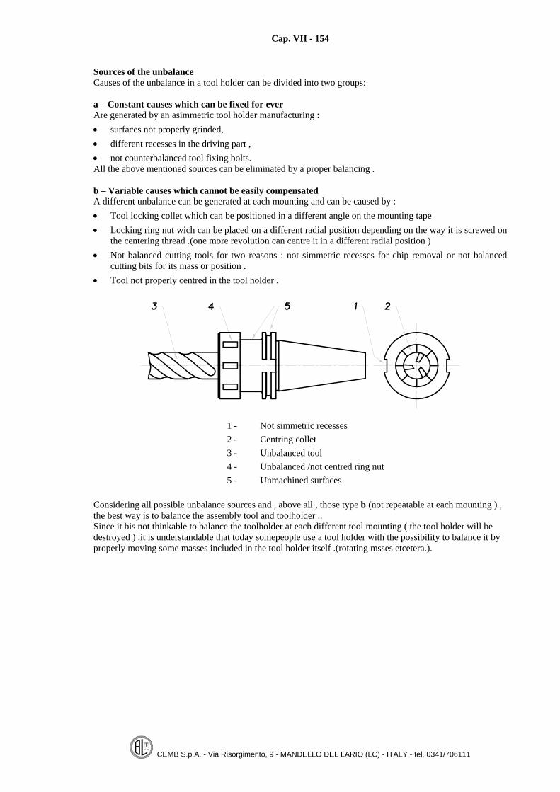
Cap. VII - 154
CEMB S.p.A. - Via Risorgimento, 9 - MANDELLO DEL LARIO (LC) - ITALY - tel. 0341/706111
Sources of the unbalanceCauses of the unbalance in a tool holder can be divided into two groups:
a – Constant causes which can be fixed for everAre generated by an asimmetric tool holder manufacturing :• surfaces not properly grinded,• different recesses in the driving part ,• not counterbalanced tool fixing bolts.All the above mentioned sources can be eliminated by a proper balancing .
b – Variable causes which cannot be easily compensatedA different unbalance can be generated at each mounting and can be caused by :• Tool locking collet which can be positioned in a different angle on the mounting tape• Locking ring nut wich can be placed on a different radial position depending on the way it is screwed on
the centering thread .(one more revolution can centre it in a different radial position )• Not balanced cutting tools for two reasons : not simmetric recesses for chip removal or not balanced
cutting bits for its mass or position .• Tool not properly centred in the tool holder .
1 - Not simmetric recesses2 - Centring collet3 - Unbalanced tool4 - Unbalanced /not centred ring nut5 - Unmachined surfaces
Considering all possible unbalance sources and , above all , those type b (not repeatable at each mounting ) ,the best way is to balance the assembly tool and toolholder ..Since it bis not thinkable to balance the toolholder at each different tool mounting ( the tool holder will bedestroyed ) .it is understandable that today somepeople use a tool holder with the possibility to balance it byproperly moving some masses included in the tool holder itself .(rotating msses etcetera.).

Cap. VII - 155
CEMB S.p.A. - Via Risorgimento, 9 - MANDELLO DEL LARIO (LC) - ITALY - tel. 0341/706111
Balancing tolerance calculation
a - ISO 1940/1 Standards
Depending on the fact we consider the tool and the toolhoder as parts of a lathe or a grinding machine , therequired balancing tolerance according to ISO 1940 is equl to G = 2,5 or G = 1.The total admitted residual unbalance for a tool / toolholder is calculated , for quality grade G = 2,5 ,according to the next formula :
MN
U ⋅=24000
dove: U = Total acceptable residual unbalance [gr·mm]
N = Maximum tool holder service speed [RPM]
M = Total mass ( tool and toolholder ) [kg]
For G = 1 the accepted values are 2,5 times lower and the following formula is applicable:
MN
U ⋅=9500
At 24000 RPM the admitted specific unbalance E [µ] for the quality G 2,5 is 1 µ , while for quality 1 is0,4 µ = 0,4 gr·mm/kg.
b – Recommended unbalance tolerance
We start by considering that an optimum unbalance tolerance shall have the following benefits :
1) It is easy to be obtained with the balancing machines today available in the market with acceptableproduction costs . (low time required).
2) It easy verified even after different mountings and desmountings .3) The related centrifugal forces on the spindle bearings are acceptable or lower compared to the cutting
forces .Considering also that the balancing of a toolholder requires the use of a mounting adapter whose mechaniccentring accuracy (centring repeatability ) is not better than 1 or 2 microns, we think it right not to require atolerance better than quality G = 2,5.Taking also into consideration the accuracy of the standard balancing machines , today available in themarket , the acceptable residual unbalance for a toolholder can be calculated by the use of the followingformula :
MN
U ⋅=24000
(valid for N ≤ 12000 RPM)
MU ⋅= 2 (valid for N > 12000 RPM)
If the value for U , calculated by the previous formula ,is lower than 0,5 gr·mm it is accepted the valueU = 0,5 gr·mm.
where U [gr·mm] = Maximum admitted residual unbalanceN [giri/min] = Maximum toolholder servise speedM [kg] = Total mass(toolholder and tool )
What above specified means that the minimum accepted total residual unbalance is not lower than 0,5 gr·mmand that mechanic centring repeatability of the used adapter is within 1 micron.

Cap. VII - 156
CEMB S.p.A. - Via Risorgimento, 9 - MANDELLO DEL LARIO (LC) - ITALY - tel. 0341/706111
It is better , in oder to verify the residal unbalance at each following mounting , that the measured unbalancevalues during the balancing process are lower that the ones calculated by the previous formula (lower by50 %) ; this means :
MN
U ⋅=12000
(valid for N ≤ 12000 RPM)
MU ⋅=1 (valid for N > 12000 RPM)
U ≥ 0,5 gr·mm
When balancing on two planes, necessary for toolholders having long axial dimensions (L > 2D), Theacceptable residual unbalance on the two different planes U1, U2 is calculated by the following formula :
UUU ⋅== 221 if the distance between the two planes ≥ 80 mm
UUU ⋅== 421 if the distance between the two planes < 80 mm
In both cases the total residual unbalance (static ) shall be lower than U.
Notes:
1) The admitted tolerance on the two different planes (couple unbalance ) is bigger , under the conditionthat the total unbalance (static unbalance ) is lower than U.
2) It is advisable to balance at about 50% the calculated tolerance so that at each following mounting ,even with the errors introduced by the mounting adapter , the measured unbalance is within therequired tolerance .
Balancing speed
Tools and toolholders are rigid rotors (do not deform ) and at consequence the unbalance (mass distributionaround the axis of rotation ) does not change with speed .The right balancing speed depends on the type of used balancing machine . The balancing speed value orrange is to be chosen in order to obtain the best balancing accuracy and repeatability .with the availablebalancing machine . Normally the used balancing speed varies from 1000 and 3000 RPM (higher speed forlighter toolholders ).
The right balancing machine for toolholders
An horizontal or vertical type balancing machine can be used .The main differences are :
• The vertical axis balancing machine is sometimes more practical (easier toolholder mounting anddesmounting )
• The vertical axis balancing machine can be suitable to balance on one ( static balancing ) or on two(dynamic balancing )
• The horizontal axis balancing machine , normally belt driven , has some important advantages :-better sensitivity (0,1 gr·mm against 0,2 ÷ 0,4 gr·mm)- better balancing accuracy (0,1 ÷ 0,3 gr·mm/kg against 0,5 ÷ 1 gr·mm/kg)- possibility to balance on 1 or 2 planes- possibility to be used to blance other different rotors types
A good balancing machine for tools and toolholders must have the following features :• Measuring of the dynamic unbalance (static and couple );• Good sensitivity (0,1 ÷ 0,2 gr·mm);• Including the software to electronically compensate the errors caused by the mounting adapter
(unbalance and mounting eccentricities ) (see 3.6).

Cap. VII - 157
CEMB S.p.A. - Via Risorgimento, 9 - MANDELLO DEL LARIO (LC) - ITALY - tel. 0341/706111
Mounting adapter
The final balancing result of a toolholder is greatly influenced by the mounting adapter which is used .It is necessary to reproduce ( in the balancing machine ) the same conditions (axis of rotation ) existing inservice conditions .Following recommendations are valid:
a) With HSK type attachments it is necessary to exert a strong axial thrust so that the toolholder facecompletely touches the resting face (as it is on service conditions ).
b) With ISO type attachments the axial thrust can be reduced because the centring is granted by thecone .
It is worth mentioning that mounting adapters , copying exactly the toolhlder locking in service conditions inthe machine spindle, do not grant good repeatability for the unbalance measuring becuse some mobilecomponents (flaps ) are not sufficiently guided ( eccessive clearance ). Simpler mounting adapter can beused with easy mounting /desmounting and good repeatability in the centring ..The next sketch is an example of a good adapter used to balance HSK toolholders on an horizontal axisbalancing machine .By simply screwing a side screw the toolholder is axially locked and centered.It is absolutaly necessary to use the software for compensating the unevoidable eccentricity errors caused bythe adapter itself :
- adapter unbalance- eccentricity in the mounting .
Even if the eccentricity compensation (for the same adapter ) is valid for all the same type toolholders (having same shape and mass ) , it is advisable to repeat it at each different toolholder ( even of the sametype).
Example of a good tool holder

Cap. VII - 158
CEMB S.p.A. - Via Risorgimento, 9 - MANDELLO DEL LARIO (LC) - ITALY - tel. 0341/706111
7.10 Car wheels
a) WheelsThe european association of wheel manufacturers define the acceptable unbalance tolerance on one planeonly ( static ), according to the following figure .the acceptable residul unbalance varies only with the speed .
ES-3.04 Acceptable residual unbalance fo car wheels
b) TyresAn acceptable residual unbalance is specified according to the tyre weight .For new tyres the total acceptable unbalance in grams is Uta [gr] = k · M , where M = tyre mass in kg and ka factor varying from 2 to 4.
c) Complete car wheelsAre dynamically balanced on two planes by adding lead masses on the wheels sides ..According to ISO 1940 Standards the required tolerance is G 40. Normally a beter quality ( G = 16 ) is usedin order to reduce the final unbalance resulting from a not perfect centring of the wheel on its hub ..If the maximum unbalance per plane is bigger than 60grams the wheel is rejected .The required tolerance is 5÷10 grams per plane (car wheels ) and 30÷50 grams per plane for truck wheels.

Cap. VII - 159
CEMB S.p.A. - Via Risorgimento, 9 - MANDELLO DEL LARIO (LC) - ITALY - tel. 0341/706111
7.11 Plough shaftsAgriculture plough shafts can be considered as rotors with variable geometry because , as a function of thespeed , the position of the cutting blades can change . The high service speed (2000 – 2200 CPM) and thelength ( sometimes more than 3 meters ) may cause the service speed to be near the first natural speed (itcan be considered as a flexible rotor )..Plough shafts proper balancing requires :
• Cutting blades having more or less the same mass (nominal weight ± 25 grams).• Simmetric distribution of the cutting blades on the shaft body ( tube ) with a proper design .• Cutting blades locking system which permits a free repeatable movement above a certain speed .• Pre-balancing at a low speed (800÷1000 RPM)., with the all blades completely open .• Unbalance compensation , if possible , on the all body length .• Balance improving at different steps by gradually increasing the speed untill the maximum service speed
Notes:
1) The balancing is easier if the centre body (tube ) is rigid at all speeds.
2) The body rigidity increases with the external diameter. The wall thickness has lower influence on thetube rigidity ..
3) If the shaft is flexible , a third plane in the centre is to be used .(v. 5.13).
4) The welding of masses can originate new unbalances because of induced tube deformations ..
5) It is better to use tubes having a constant uniform wall thickness ..
6) Sometimes , at high speeds , a good balancing is achieved just adding small masses in the centreposition .
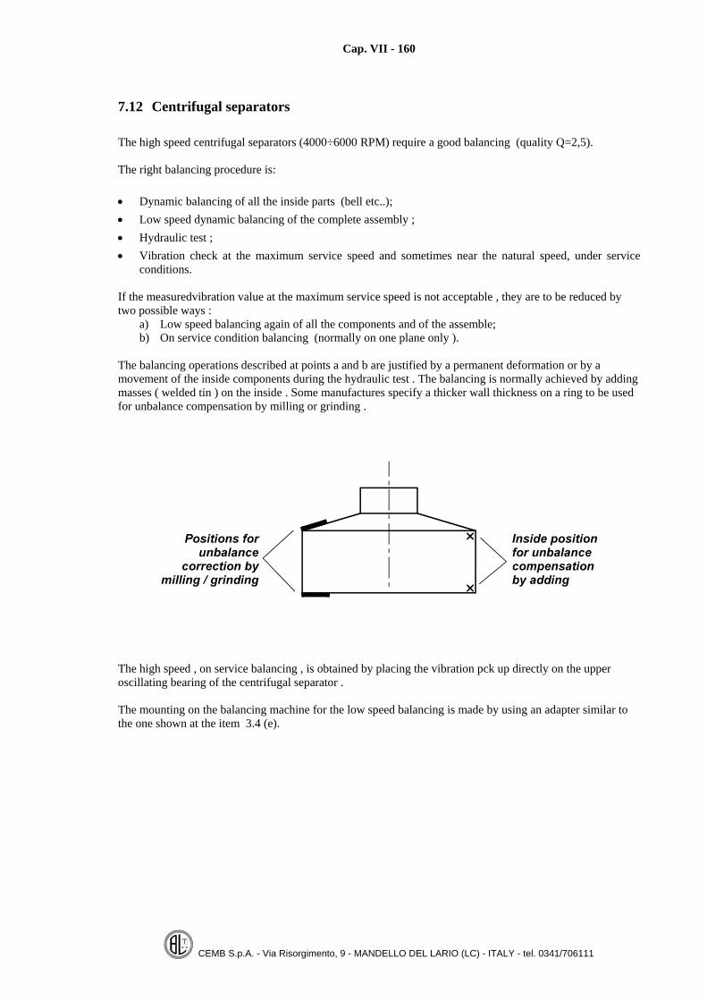
Cap. VII - 160
CEMB S.p.A. - Via Risorgimento, 9 - MANDELLO DEL LARIO (LC) - ITALY - tel. 0341/706111
7.12 Centrifugal separators
The high speed centrifugal separators (4000÷6000 RPM) require a good balancing (quality Q=2,5).
The right balancing procedure is:
• Dynamic balancing of all the inside parts (bell etc..);• Low speed dynamic balancing of the complete assembly ;• Hydraulic test ;• Vibration check at the maximum service speed and sometimes near the natural speed, under service
conditions.
If the measuredvibration value at the maximum service speed is not acceptable , they are to be reduced bytwo possible ways :
a) Low speed balancing again of all the components and of the assemble;b) On service condition balancing (normally on one plane only ).
The balancing operations described at points a and b are justified by a permanent deformation or by amovement of the inside components during the hydraulic test . The balancing is normally achieved by addingmasses ( welded tin ) on the inside . Some manufactures specify a thicker wall thickness on a ring to be usedfor unbalance compensation by milling or grinding .
The high speed , on service balancing , is obtained by placing the vibration pck up directly on the upperoscillating bearing of the centrifugal separator .
The mounting on the balancing machine for the low speed balancing is made by using an adapter similar tothe one shown at the item 3.4 (e).

Cap. VII - 161
CEMB S.p.A. - Via Risorgimento, 9 - MANDELLO DEL LARIO (LC) - ITALY - tel. 0341/706111
7.13 Electric armatures
a) Balancing toleranceNormal armatures are balanced according to quality G= 6,3 ; special armatures according to quality G= 2,5.
b) Unbalance compensation methodsAs all rotor types the electric armatures can be balanced :
b.1 By adding masses ; for example:Washers are fixed on the pegs of squirrel cage armatures;Steel plates are welded on the end faces of big alternate or continous current motors ;Steel masses ( movable on circular T slots made on the rotor end faces ) are used to balance
big alternators ;Two components compound , which hardens in a few minutes , is directly placed on the
wires of small electric armatures ;Small bolts are screwed in the existing threaded holes ( 12 ) placed on the end face
circumference of permanent magnets high speed motors .
b.2 by removing materialUnbalance correction by mass removing is normally used on automatic machines for smalland medium size armatures .Small armatures are milled on the polar expansions ;Cage rotors are axial drilled on the rotor body ;Small continous current motors are balanced with radial drillings on two lateral flanges
designed for this purpose .
Balancing by drilling Balancing by milling
Taking care of the balancing method which requires:• Milling in fixed angle positions ;• Relevant drilling depths compared to rotor dimensions ;
the automatic balancing machine can reach optimum performances (URR between 80 and 90%) only if thesoftware for balancing by components and by not linear drilling is available .With deep drills the correctionradius varies (radial drillings ) or the balancing plane changes (axial drilling ).
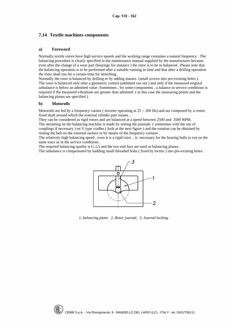
Cap. VII - 162
CEMB S.p.A. - Via Risorgimento, 9 - MANDELLO DEL LARIO (LC) - ITALY - tel. 0341/706111
7.14 Textile machines components
a) ForewordNormally textile rotors have high service speeds and the working range containes a natural frequency . Thebalancing procedure is clearly specified in the maintenance manual supplied by the manufacturer becauseeven after the change of a wear part (bearings for instance ) the rotor is to be re-balanced . Please note thatthe balancing operation is to be performed after a suitable running in time and that after a drilling operationthe rotor shall run for a certain time for stretching .Normally the rotor is balanced by drilling or by adding masses (small screws into pre-existing holes ).The rotor is balanced only after a geometric control (admitted run out ) and only if the measured originalunbalance is below an admitted value .Sometimes , for some components , a balance in service conditions isrequired if the measured vibrations are greater than admitted ( in this case the measuring points and thebalancing planes are specified ).
b) MotorollsMotorolls are fed by a frequency varitor ( inverter operating at 25 ÷ 200 Hz) and are composed by a centrefixed shaft around which the external cilinder part rotates ..They can be considered as rigid rotors and are balanced at a speed between 2500 and 3500 RPM.The mounting on the balancing machine is made by resting the journals ( sometimes with the use ofcouplings if necessary ) on V type cradles ( look at the next figure ) and the rotation can be obtained byresting the belt on the external surface or by means of the frequency variator .The relatively high balancing speed , even it is a rigid rotor , is necessary for the bearing balls to run on thesame trace as in the service conditions .The required balancing quality is G 2,5 and the two end face are used as balancing planes .The unbalance is compensated by badding small threaded bolts ( fixed by loctite ) into pre-existing holes .
1, balancing plane 2, Rotor journal; 3, Journal locking .

Cap. VII - 163
CEMB S.p.A. - Via Risorgimento, 9 - MANDELLO DEL LARIO (LC) - ITALY - tel. 0341/706111
c) ChucksChucks are flexible rotors and are balanced , depending on the model in one , two , or three planes .A special mounting cradle ( simulating the service conditions ) is used to mount the chuck in the balancingmachine .(see figure ).
1, Machine bed; 2, Machine supports; 3, Mounting cradle ; 4, Driving motor ;5, Chuck; I, II, III, IV, Balancing planes
The balancing is achieved by radial drilling (in planes I, IV also by axial drilling ). The required balancingtolerance is G 2,5 and the balancing speed varies from 1200 and 2200 RPM. In order to avoid damage to thechuck with unusefull holes , it is advisable to balance it by adding plasticine on the external surface and todrill it only at the end when the required tolerance has been surely achieved . It is necessary to keep in mindthat :• Before the unbalance measurement , the rotor has to be kept running in for the time specified by the
manufacturer• The drilling operation and the machine start up ( spinning ) causes an elastic deformation which must
desappear before taking the unbalance measurement . ( the rotor is kept running until the unbalancereading is constant ).
Even with a low speed balancing , acceptable results are obtainable if the measured unbalance is correctedin adistributed way (for instance 30 ÷ 40 % of the measured static unbalance is corrected on plane III and theremaining unbalance on planes IIand IV).Once pre-balanced at low speed , the chuck is tested at different speeds up to the service speed including itsnatural speed and the vibration ( pick up signal ) is recorded ; if it keeps within specified values the chuck isbalanced otherwise a high speed balancing ( near the critic speed ) in a specified plane is to be performed asdescribed at paragraph 4.3 .For maintenance purposes , after bearings change ,a good low speed balancing is enough .A finer balancing at low speed is obtained by using the self learning mode (see. par. 6.11).
Notes: Some manufacturers specify the acceptable value for the balancing machine supports vibrationswith reference to a well defined balancing machine model , so users of other types of balancingmchines must calculate , in an experimental way , what is the acceptable vibration for theirmachine by using a test chuck surely balanced and recording the vibration values over the speedrange ...It should be better , as reported on paragraph 5.16 , if the accepted tolerance is specified in gr·mm(force exerted on the machine support ) ; this way the tolerance is not tied to a balancing machinetype and model .

Cap. VII - 164
CEMB S.p.A. - Via Risorgimento, 9 - MANDELLO DEL LARIO (LC) - ITALY - tel. 0341/706111
d) Reverse shaftsThey are flexible rotors running high speed over the first and sometimes over the second natural speeds(running speed up to 24'000 RPM).The required tolerance is G 2,5 and there are 3 or 5 balancing planes depending on shaft rigidity and on itsnatural speeds .The balancing is obtained by following the standard modal balancing described at paragraph 5.13.Also for these shafts the machine supports acceptable vibrations are normally specified ( same comments ofthe previous note are valid) .It is advisable to previouly balance the reverse shaft by adding provisional plasticine and then proceed bydrilling . becuase , as shown at paragraph 5.13 , modal balancing requires different steps with possiblechanges.Also for balancing these types of rotors it is better to use a machine with the self learning calibration mode orspecific calibration .( see. par. 6.11).
Balancing planes on a reverse shft passing only through the first natural speed
Balancing planes on a reverse shaft passing through the first and second natural speeds.
Notes: 1) Sometimes the shaft low speed unbalance is not important and the manufacturer specifies only thebalancing at high speed near the critical speed ; in this case the goal is to reduce the shaft bendingvalue at certain shaft positions ..( the balancing mass is calculated by the vectorial method )2) On a flexible rotor , even of the same type , the critic speed is different ; so the ( high ) balancingspeed varies from a rotor to another of vthe same shape ..

Cap. VII - 165
CEMB S.p.A. - Via Risorgimento, 9 - MANDELLO DEL LARIO (LC) - ITALY - tel. 0341/706111
7.15 Relationship Unbalance-drill depth


Cap. VIII - 167
CEMB S.p.A. - Via Risorgimento, 9 - MANDELLO DEL LARIO (LC) - ITALY - tel. 0341/706111
CHAPTER 8
BALANCING MACHINE CONTROL
8.1 Test rotorThe quality control of a universal balancing machine, as far as concerns the minimum achievable residualunbalance and the unbalance reduction ratio, is obtained by using a standard test rotor , according toISO 2953 standards The main features of ISO test rotors are :
• Its residual unbalance is very low• Its shape is simple• It is surely rigid• The positions for the applied test masses (planes and radius ) are well defined
For the same tests or only for calibration tests , a different type of test rotor ,can be used ,if agreed betweenthe Manufacturer and the User , under the condition that it complies with the above listed features .For special purposes balancing machines (automatic machines ) the test rotor or master rotor can be a rotorsimilar to the ones processed (a pulley ,a brake disc ,a crankshaft ,f.i.) having the same geometricdimensions but with better tolerances (perfect ninety degrees between the centring hole and the supportingsurface ) and hardened working surfaces .(of course the master rotor complies with the above reportedspecifications ).
The ISO test rotor ,to be used on a universal balancing machine , should have a mass lower than 1/3 themaximum machine weight capacity.

Cap. VIII - 168
CEMB S.p.A. - Via Risorgimento, 9 - MANDELLO DEL LARIO (LC) - ITALY - tel. 0341/706111
a - Test rotors type A ,for vertical axis balancing machines
Suggested dimensions ,masses and speed for test rotors type A (vertical machines )
RotorN° 1 2 3 4 5Rotor mass M kg 1.1 3.5 11 35 110Major diameter D mm 110 160 230 245 510Minor diameter d = 0.9 D mm 99 144 206 310 460Height H = 0.5 D mm 55 80 127 170 255X = 0.075 D mm 8 12 19 25 38Y = 0.175 D mm 20 30 45 60 90Z = 0.175 D mm 20 30 45 60 90F = 0.06 D mm 6.5 9.5 13 20 30G mm M3 M4 M5 M6 M8I mm 50.8 50.8 114.3 114.3 114.3J mm 0.4 x 45° 0.4 x 45° 0.4 x 45° 0.4 x 45° 0.4 x 45°K mm 4.2 4.2 4.2 4.2 4.2R mm 76.2 76.2 133.35 133.35 133.35O mm 6.6 6.6 10.3 10.3 10.3Highest test speed giri/min 20 000 14 000 10 000 6 000 4 000

Cap. VIII - 169
CEMB S.p.A. - Via Risorgimento, 9 - MANDELLO DEL LARIO (LC) - ITALY - tel. 0341/706111
b - Test rotors type B, for horizontal axis balancing machines
Suggested dimensions ,masses ,and speed for test rotors type B
Rotor N° 1 2 3 4 5 6 7Rotor mass M kg 0.5 1.6 5 16 50 160 500Major diameter D mm 38 56 82 120 176 260 380Overall length L = 2.5 D mm 95 140 205 300 440 650 950Shaft diameter d = 0.3 D mm 11 17 25 36 58 78 114Bearing distance 2D = A+B+C mm 76 112 164 240 352 520 760A, C = 0.5 D mm 19 28 41 60 88 130 190B = 1 D mm 38 56 82 120 176 260 380E = 0.25 D mm 9.5 14 20.5 30 44 65 95F = 0.5 D mm 19 28 41 60 88 130 190P1 mm 31 46 72 108 160 240 350H mm - - - 4 1.4 1.8 2.2K mm - - - 7 30 42 57P2 mm - - - 30 47 62 84N mm M2 M3 M4 M5 M6 M8 M10Critical speed = 7 600 000/D giri/min 200 000 140 000 95 000 65 000 45 000 30 000 20 000Highest test speed giri/min 20 000 14 000 9 500 6 500 4 500 3 000 2 000
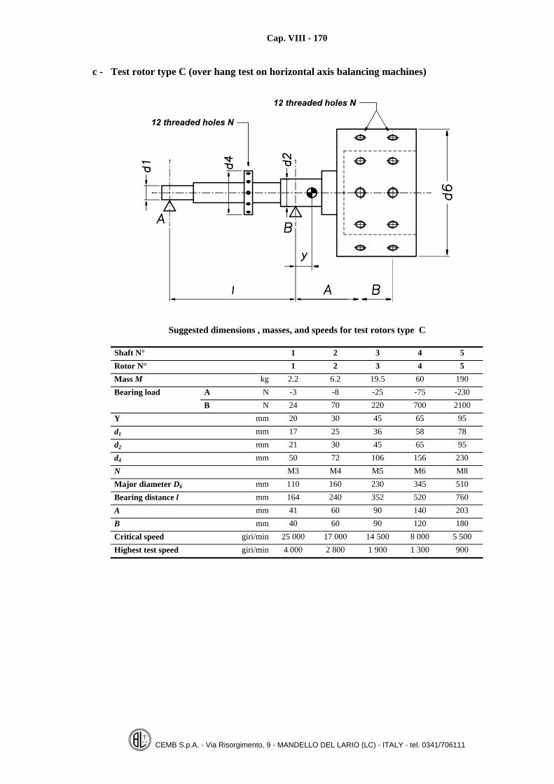
Cap. VIII - 170
CEMB S.p.A. - Via Risorgimento, 9 - MANDELLO DEL LARIO (LC) - ITALY - tel. 0341/706111
c - Test rotor type C (over hang test on horizontal axis balancing machines)
Suggested dimensions , masses, and speeds for test rotors type C
Shaft N° 1 2 3 4 5Rotor N° 1 2 3 4 5Mass M kg 2.2 6.2 19.5 60 190Bearing load A N -3 -8 -25 -75 -230
B N 24 70 220 700 2100Y mm 20 30 45 65 95d1 mm 17 25 36 58 78d2 mm 21 30 45 65 95d4 mm 50 72 106 156 230N M3 M4 M5 M6 M8Major diameter D6 mm 110 160 230 345 510Bearing distance l mm 164 240 352 520 760A mm 41 60 90 140 203B mm 40 60 90 120 180Critical speed giri/min 25 000 17 000 14 500 8 000 5 500Highest test speed giri/min 4 000 2 800 1 900 1 300 900

Cap. VIII - 171
CEMB S.p.A. - Via Risorgimento, 9 - MANDELLO DEL LARIO (LC) - ITALY - tel. 0341/706111
8.2 Calibration control
The test is performed in order to verify if the machine is properly calibrated and the measured unbalancevalues are the right ones .The test or master rotor is to be used .When the rotor is mounted ,the geometric data related to the balancing planes are set up (a, b, c, R1, R2).The control is composed by :
a - Electric zero control
With the pick up cables disconnected ,the measured unbalance is to be zero. ;it means that no noise comesfrom the electronics .In the modern microprocessor machines, this control is possible only by the use of special connectors whichreplace sensor cable (if cables are disconnected the machine stops and gives a warning message :cables pickup disconnected ).
b - Calibration control
The measured unbalance ,for the test rotor ,should be zero or very low .When using vertical axis balancing machines ,even if the master rotor is balanced ,an unbalance value can bemeasured , because of the error which can be introduced by the mounting adapter .(tool unbalance oreccentricity ,look at chapter 3) ; as consequence , the mounting tool eccentricity compensation shall be used . Also on horizontal axis balancing machines ,small original unbalances can be found on the master rotorcaused by the driving joint or by rotor journals not perfectly grounded (by changing the supporting points ,the axis of rotation can change ).The plasticine is used to reduce , if necessary , the master rotor unbalance .Known masses (for instance 10 and 50 grams )are applied on the test rotor on the available different angularpositions ,first on the plane one ,then on the plane number two .
The calibration test is positively passed if all the measured values , satisfy the following criteria :
• The error on the measured unbalance is : ± 10%• The error on the position unbalance is : ± 3°• Maximum residual unbalance on the opposite plane (plane separation ) : 10% of the applied mass.
The error is calculated as : (measured value-nominal value ) / nominal value .
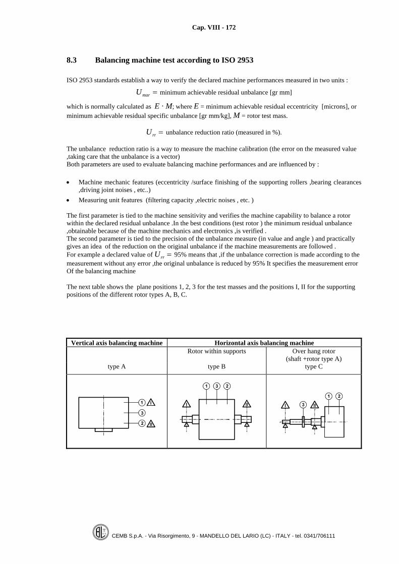
Cap. VIII - 172
CEMB S.p.A. - Via Risorgimento, 9 - MANDELLO DEL LARIO (LC) - ITALY - tel. 0341/706111
8.3 Balancing machine test according to ISO 2953
ISO 2953 standards establish a way to verify the declared machine performances measured in two units :
Umar = minimum achievable residual unbalance [gr mm]
which is normally calculated as E · M; where E = minimum achievable residual eccentricity [microns], orminimum achievable residual specific unbalance [gr mm/kg], M = rotor test mass.
Urr = unbalance reduction ratio (measured in %).
The unbalance reduction ratio is a way to measure the machine calibration (the error on the measured value,taking care that the unbalance is a vector)Both parameters are used to evaluate balancing machine performances and are influenced by :
• Machine mechanic features (eccentricity /surface finishing of the supporting rollers ,bearing clearances,driving joint noises , etc..)
• Measuring unit features (filtering capacity ,electric noises , etc. )
The first parameter is tied to the machine sensitivity and verifies the machine capability to balance a rotorwithin the declared residual unbalance .In the best conditions (test rotor ) the minimum residual unbalance,obtainable because of the machine mechanics and electronics ,is verified .The second parameter is tied to the precision of the unbalance measure (in value and angle ) and practicallygives an idea of the reduction on the original unbalance if the machine measurements are followed .For example a declared value of Urr = 95% means that ,if the unbalance correction is made according to themeasurement without any error ,the original unbalance is reduced by 95% It specifies the measurement errorOf the balancing machine
The next table shows the plane positions 1, 2, 3 for the test masses and the positions I, II for the supportingpositions of the different rotor types A, B, C.
Vertical axis balancing machine Horizontal axis balancing machineRotor within supports Over hang rotor
(shaft +rotor type A)type A type B type C

Cap. VIII - 173
CEMB S.p.A. - Via Risorgimento, 9 - MANDELLO DEL LARIO (LC) - ITALY - tel. 0341/706111
Test for verifying the declared value of Umar
• A test mass equal to 10 Umar is required
• 4 spins can be used to reduce the test rotor unbalance to a minimum value (below 1 0r 2 Umar )
• The test mass is placed on the balancing plane N.3.• The rotor is spun and the unbalance measured on the planes I, II, .is recorded .• Measurements are repeated by placing the test mass on the all different angular positions.• The next table is filled up ; with the same values the next curve is drawn.
Note :Instead of one single mass ,two masses each one equal to 5 Umar , to be placed on the two planes 1and 2 in the same angular position , can be used . (they are equivalent to the double mass placed in theintermediate plane N.3).
POSITION FOR THE TEST MASS
0° 30° 60° 90° 120° 150° 180° 210° 240° 270° 300° 330°
Measuredunbalance value
Left plane (lowerplane)Right plane(upper plane)
Table containing the measured values obtained during the sensitivity test (Umar test ) onhorizontal and vertical machines. (lower plane and upper plane refer to the vertical axis
balancing machines).
Curve of the values registered on the previous table . The test is passed if all thesine curve points are kept within a range of (0,88 ÷ 1,12).
Instead of drawing the above curve ,it is possible to calculate the average measured unbalance :Au = (Sum of the unbalance values )/12The sensitivity test is passed if the maximum measured value is lower than 1.12xAu and the minimummeasured value is greater than 0.88xAu

Cap. VIII - 174
CEMB S.p.A. - Via Risorgimento, 9 - MANDELLO DEL LARIO (LC) - ITALY - tel. 0341/706111
Test for verifying the declared value of Urr
Twin double masses are required
• 2 equal stationary masses Ustat having each one a mass value between 20 and 60 Umar
• 2 equal travelling masses Utrav having each one a mass equal to 5 Ustaz• The two stationary masses (Ustaz) are placed each one on an arbitrary and different angle ,one on the
left one the right balancing plane .• The same thing is done for the two travelling masses (Utrav).
• On the annexed table the following values are registered : positions of the test masses on the two planesand the related measured unbalance.
• The unbalances values are measured after moving (clockwise direction for plane 1 and anticlockwisedirection for plane 2) the travelling masses .
• The unbalance measured values (11) ,together with test masses angular positions are recorded in theabove mentioned table
• The unbalance measured values (amplitudes )are then divided by Umar and the new calculated valuesare reported as single points in the annexed drawing .
• The vector position reveals the achieved value for (URR) Please note that a not acceptable value forURR can be caused even only by an error on the measured unbalance angle position .
Note : With over hang test rotors (type C) the stationary masses Ustaz are equal to 60÷100 Umar.

Cap. VIII - 175
CEMB S.p.A. - Via Risorgimento, 9 - MANDELLO DEL LARIO (LC) - ITALY - tel. 0341/706111
Table for URR test data
Date Balancing machinemodel____________________________
Test rotor N°_________ Mass P = ________kg Over hang test rotor N°_______________Min. achievable eccentricity e = _______μm Mass P= __________kg
Unbalance radius r = _______mm Stat.mass 25 Umar = __________gr
Umar per plane = P er⋅
2= ________gr Trav.mass 125 Umar
=__________gr
Test mass angle Left plane Right plane
Spin Left plane Right plane Measuredunbalance value
gSrmo
Measuredunbalance value
gSrmo
Stationary
Travelling
Stationary
Travelling
g Angle g Angle
1
2
3
4
5
6
7
8
9
10
11

Cap. VIII - 176
CEMB S.p.A. - Via Risorgimento, 9 - MANDELLO DEL LARIO (LC) - ITALY - tel. 0341/706111
Drawing to verify the obtained value for URR for two balancing planes .

Cap. VIII - 177
CEMB S.p.A. - Via Risorgimento, 9 - MANDELLO DEL LARIO (LC) - ITALY - tel. 0341/706111
8.4 Balancing machine control according to ISO 9000 standards .
A lot of companies ,using balancing machines ,are quality certified according to ISO 9000. The balancingmachine , as every measuring instrument ,is to be checked and the quality manual clearly specifies all thesteps required to verify the balancing machine and the time interval between each check..The quality manual can require :
a - Calibration check made by the machine manufacturer or by a certified company
The company quality control manual must specify :
1) The name of the company taking care of the machine calibration control;2) The procedure currently used for calibration check;3) The time interval between each control (normally once per year , in special cases ,for instance nuclear or
aeronautic industries ,every month or every six months ) .
The technician verifies the machine calibration , if necessary makes the required modifications ,puts onthe machine a stick certifying the calibration and its validity ,and provides an official calibrationcertificate .
b - Calibration check self made by the company quality control section
The quality control manual must specify :
1) The test rotor to be used ,
It ca be :
1.1) ISO test rotor (look 8.1),normally used for general purposes machines ..1.2) Rigid rotor similar to the produced pieces (for instance a fan:, or a pulley or a brake disc ,etc. ).The used test rotor must have the following features :
- Grounded and hardened supporting journals.- Test masses can be added on clear and fixed positions- Low value original unbalance.
2) Test masses to be used
The used test masses must be :- Certified as amount- Easily mounted and removed
3) The mounting position of the test rotor on the balancing machine supports
The machine set up parameters a, b, c, R1, R2 are clearly specified together the value of thebalancing speed to be used for the test ,if the machine is a variable speed one .On the modern balancing machines , the test rotor parameters are saved in a special program andrecalled when necessary ..
Cap. VIII - 178
CEMB S.p.A. - Via Risorgimento, 9 - MANDELLO DEL LARIO (LC) - ITALY - tel. 0341/706111
4) Step by step operations , for example :
- Mount the test rotor on the balancing machine
- Recall set up data from memory position N°1
- Verify that the set up data are: a =100, b =300, c =100, R1= R2=100
- Verify that the actual mounting position of the test rotor on the balancing machine is inagreement with the set up data
- Spin the rotor slowly up to the demanded balancing speed
- Verify that the test rotor original unbalance is very low ,if necessary using theeccentricity adapter compensation
- Add the test mass n°1 (f.i. 10 grs. ) on the left balancing plane , on the radius R1 (on arandom angular position )
- Spin the rotor and write the unbalance measured values on the test table
- Move the mass in the next available angle position ,and take a new reading
- When all left positions have been used ,move the test mass on the right plane andrepeat all the measurements
At each reading ,the measured values are written in the test table
5) Actions to be done , in case of negatives results (to call the manufacture after sale service ,forexample )

Cap. VIII - 179
CEMB S.p.A. - Via Risorgimento, 9 - MANDELLO DEL LARIO (LC) - ITALY - tel. 0341/706111
6 )Test certificate module
An example is shown :
Balancing machine : CEMB ZC 20/TC/6VSerial Nr. 3000Test rotor ISO N.2Balancing speed 800 RPMSet up data a=28, b=56, c=28, R1=28, R2=28
Left plane Right plane
Value [gr] Angle Value [gr] Angle
Measured test rotor original unbalance 0,2 28 0,1 33Admitted values 0,4 – 0,4 –
Measured unbalance values ,with the testmass N°1 (10 gr) placed on the left plane,in sequence on the angular positions :. α =0 α =90 α =180 α =270
9.99.89.8
10.1
189
181270
0.30.40.30.2
2480
160200
Admitted values 10 ± 1 α ± 3 1 –
Measured unbalance values with the testmass N°1 (10 gr) placed on the right plane ,in sequence on the angular positions : β = 0β = 90β = 180β = 270
0.30.20.30.1
1080
170280
9.89.99.9
10.1
089
181271
Admitted values 1 – 10 ± 1 β ± 3Test result :positive Date : 30.11.98 Operator : Caio
Depending on the used test rotor ,the measurement points can be more ,because more angle positions areavailable .The same test measurements can be repeated with a different test mass ;in order to check machine calibrationwith a different unbalanceThe selected values for the two test masses can be related to the required tolerances (10 or 5 times ) and tothe averaged measured unbalance .If all the measured values ,included in the above table ,are processed by using the normal statistic rules , inthe case that the original test rotor unbalance is a small percent of the test masses and the number of readingsare sufficiently high , the evaluation of the machine incertitude is possible (for statistic reasons it is possibleto repeat the measure several times so that machine repeatability can be better evaluated .)

REFERENCES
1) ISO 1940 / 1, 2. Standards Balance quality requirements of rigid rotors.
2) ISO 11342.Standards Methods and criteria for the mechanical balancing of flexible rotors.
3) CEMB N. 3 technical book “Technical elements in balancing”, L. Buzzi
4) CEMB N. 8 technical book “Balancing accuracy of rigid rotors”, L. Buzzi
5) CEMB N. 19 technical book “Crankshaft balancing”, L. Buzzi - G. Manni
6) Vibration theory and applications. W.T. Thomson
7) CEMB N. 18 technical book “Cars wheels balancing”, L. Buzzi
8) CEMB N. 23 technical book “Controllo delle vibrazioni nelle macchine in servizio”, L. Buzzi - G.Manni
9) Dispensa tecnica CEMB “Wheels unbalance control”, G. Manni
10) EUWA Standards ES 3.04 “Definition of static unbalance for car wheels”