Embed Size (px)
Citation preview

Ball Rail Tables TKK
X4
12
34
56
12
39
10
114 125 136 147 158 16
X3
X1
X2
X30
Indramat
AC-CONTROLLER DANGER!
High voltageDanger of electrical shock
Do not touch electrical connnections for
5 minutes after switching power off.
Read and follow Safety instructions for
Electrical Drives´ manual
DOK-GENERAL-DRIVE******* SVS
before operating
S2
S3
S1
8.8
X8
The Drive & Control Company
2 Ball Rail Tables TKK R310A 2501 (2007.10)Bosch Rexroth Corporation
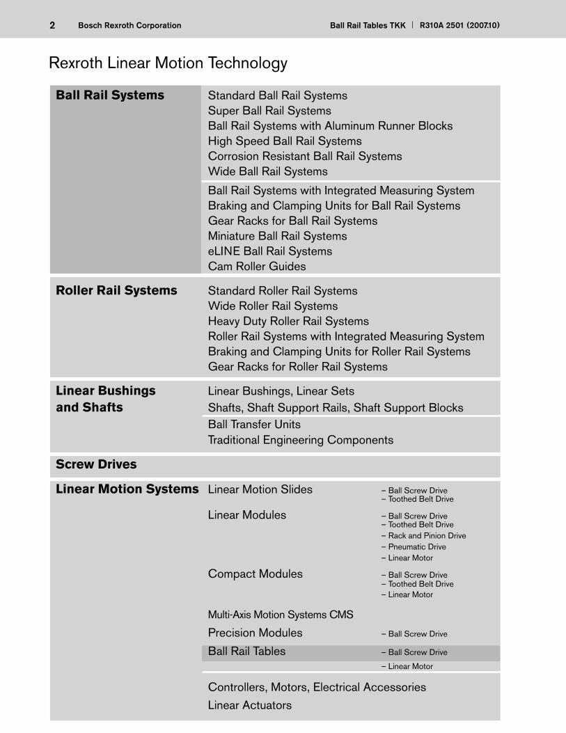
Rexroth Linear Motion Technology
Ball Rail Systems Standard Ball Rail Systems Super Ball Rail Systems Ball Rail Systems with Aluminum Runner Blocks High Speed Ball Rail Systems Corrosion Resistant Ball Rail Systems Wide Ball Rail Systems
Ball Rail Systems with Integrated Measuring System Braking and Clamping Units for Ball Rail Systems Gear Racks for Ball Rail Systems Miniature Ball Rail Systems eLINE Ball Rail Systems Cam Roller Guides
Roller Rail Systems Standard Roller Rail Systems Wide Roller Rail Systems Heavy Duty Roller Rail Systems Roller Rail Systems with Integrated Measuring System Braking and Clamping Units for Roller Rail Systems Gear Racks for Roller Rail Systems
Linear Bushings Linear Bushings, Linear Setsand Shafts Shafts, Shaft Support Rails, Shaft Support Blocks Ball Transfer Units Traditional Engineering Components
Screw Drives
Linear Motion Systems Linear Motion Slides – Ball Screw Drive – Toothed Belt Drive
Linear Modules – Ball Screw Drive – Toothed Belt Drive – Rack and Pinion Drive – Pneumatic Drive – Linear Motor
Compact Modules – Ball Screw Drive – Toothed Belt Drive – Linear Motor
Multi-Axis Motion Systems CMS
Precision Modules – Ball Screw Drive
Ball Rail Tables – Ball Screw Drive
– Linear Motor
Controllers, Motors, Electrical Accessories
Linear Actuators

3R310A 2501 (2007.10) Ball Rail Tables TKK Bosch Rexroth Corporation
4
Product Overview 6– Motor Preselection 8 – Type Designation, Sizes 10– Structure 12
Mounting, Accuracy 14
Technical Data 16– General system data 16– Permissible speeds 18– Permissible drive torque, fi xed bearing end 19– Drive data of the side drive with timing belt, fl oating bearing end 20 – Technical data AC servomotors 20
Calculation Information 22– Formulas 22– Calculation example 24
Options Table, Dimension Drawings 26– TKK 15-155 AI 26 – TKK 20-225 AI 32 – TKK 20-225 St 36 – TKK 30-325 AI 42 – TKK 30-325 St 46 – TKK 35-455 AI 52
Switch Mounting Arrangements, Accessories 58– Overview of switching system 58 – Motors 60 – Documentation 62 – Mounting accessories 65
Connection System 66
Request for Quotation/Order Form 72
A Solution to Many Problems
4 Ball Rail Tables TKK R310A 2501 (2007.10)Bosch Rexroth Corporation
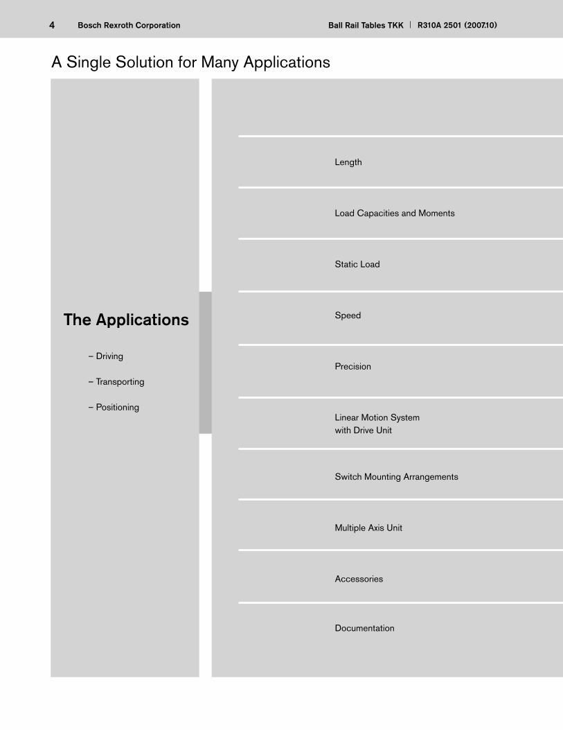
– Driving – Transporting
– Positioning
The Applications
Length
Load Capacities and Moments
Static Load
Speed
Precision
Linear Motion Systemwith Drive Unit
Switch Mounting Arrangements
Multiple Axis Unit
Accessories
Documentation
A Single Solution for Many Applications
5R310A 2501 (2007.10) Ball Rail Tables TKK Bosch Rexroth Corporation
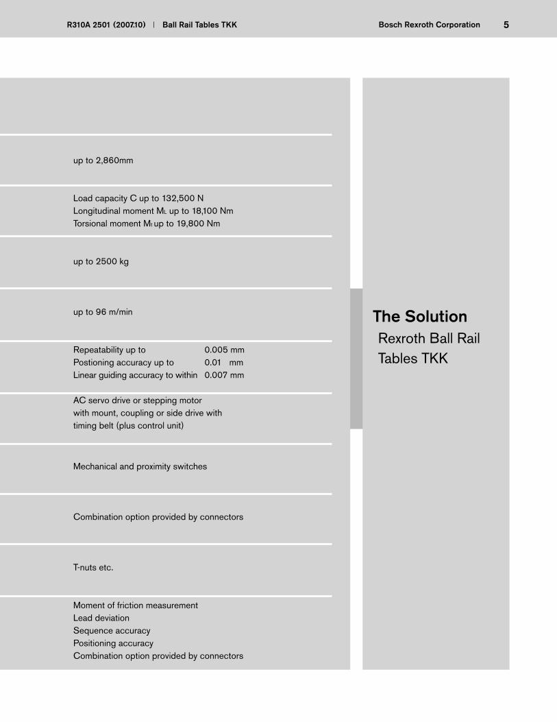
The solutionThe SolutionRexroth Ball Rail Tables TKK
up to 2,860mm
Load capacity C up to 132,500 NLongitudinal moment ML up to 18,100 NmTorsional moment Mt up to 19,800 Nm
up to 2500 kg
up to 96 m/min
Repeatability up to 0.005 mmPostioning accuracy up to 0.01 mmLinear guiding accuracy to within 0.007 mm
AC servo drive or stepping motorwith mount, coupling or side drive withtiming belt (plus control unit)
Mechanical and proximity switches
Combination option provided by connectors
T-nuts etc.
Moment of friction measurementLead deviationSequence accuracyPositioning accuracyCombination option provided by connectors
6 Ball Rail Tables TKK R310A 2501 (2007.10)Bosch Rexroth Corporation
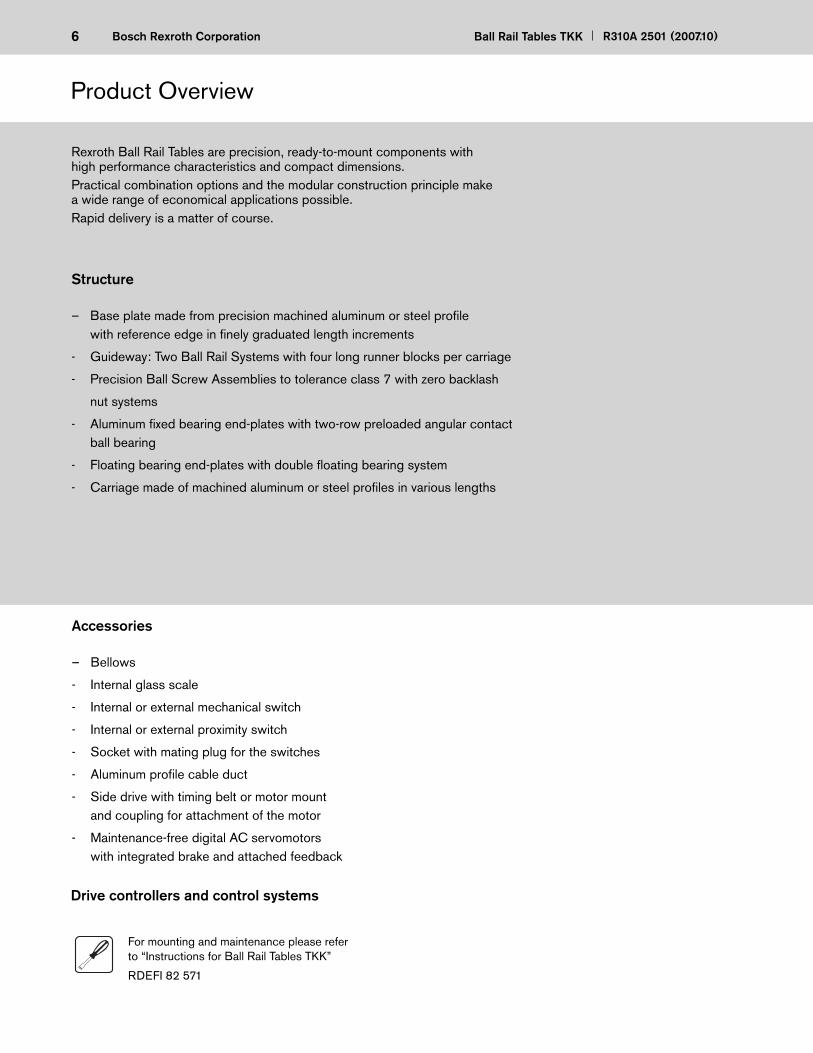
Accessories
– Bellows
- Internal glass scale
- Internal or external mechanical switch
- Internal or external proximity switch
- Socket with mating plug for the switches
- Aluminum profi le cable duct
- Side drive with timing belt or motor mount and coupling for attachment of the motor
- Maintenance-free digital AC servomotors with integrated brake and attached feedback
Rexroth Ball Rail Tables are precision, ready-to-mount components with high performance characteristics and compact dimensions. Practical combination options and the modular construction principle make a wide range of economical applications possible. Rapid delivery is a matter of course.
Structure
– Base plate made from precision machined aluminum or steel profi lewith reference edge in fi nely graduated length increments
- Guideway: Two Ball Rail Systems with four long runner blocks per carriage
- Precision Ball Screw Assemblies to tolerance class 7 with zero backlash
nut systems
- Aluminum fi xed bearing end-plates with two-row preloaded angular contact ball bearing
- Floating bearing end-plates with double fl oating bearing system
- Carriage made of machined aluminum or steel profi les in various lengths
Product Overview
For mounting and maintenance please refer to “Instructions for Ball Rail Tables TKK”
RDEFI 82 571
Drive controllers and control systems

7R310A 2501 (2007.10) Ball Rail Tables TKK Bosch Rexroth Corporation
No loss of load capacity due to rigid table design, reference edge for runner blocks, parallel drilled nut mounting.
Increased load-bearing capacity ge-nerally permits the use of a smaller Ball Rail Table.
Oil and temperature resistant bel-lows mounting provided by mecha-nical clamping of the last folds.
High speeds over long distances are possible by using the combina-tion of Ball Rail Systems, and Ball Screws which offer large diameters and leads, and double fl oating bea-ring systems.
Rapid assembly provided by ma-chined reference edge on the base plate.
Switches adjustable over the full length of travel. Can be mounted either internally, pro tected by the bellows, or extern ally, in freely ac-cessible positions.
Inexpensive maintenance of the four runner blocks and the precision ball screw assembly. Lubrication via one central lubrication point. A lube port is readily accessible on each side of the carriage.(Suitable for grease lubrication only)
Protection of integrated com-ponents provided by high-quality, oil and moisture resistant welded bellows.
Features
8 Ball Rail Tables TKK R310A 2501 (2007.10)Bosch Rexroth Corporation
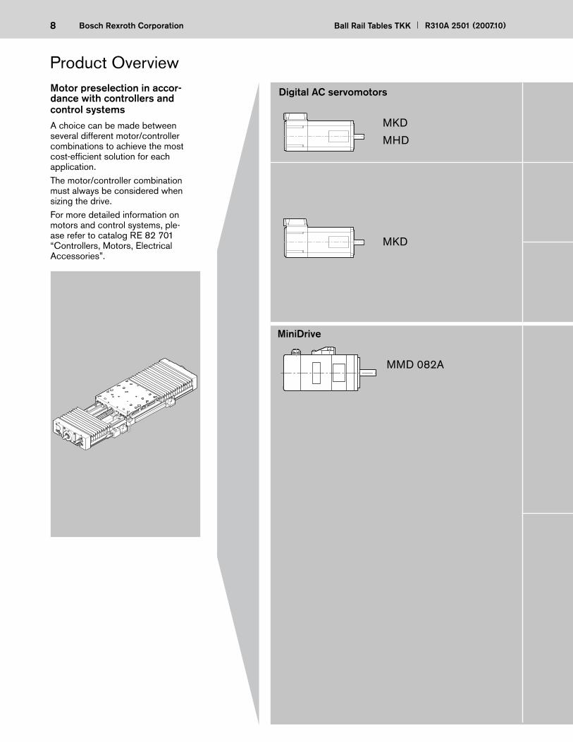
MKD
MHD
MKD
Product Overview
Digital AC servomotorsMotor preselection in accor-dance with controllers and control systemsA choice can be made between several different motor/controller combinations to achieve the most cost-effi cient solution for each application.The motor/controller combination must always be considered when sizing the drive.For more detailed information on motors and control systems, ple-ase refer to catalog RE 82 701 “Controllers, Motors, Electrical Accessories”.
MMD 082A
MiniDrive

9R310A 2501 (2007.10) Ball Rail Tables TKK Bosch Rexroth Corporation
Ball Rail Tables can be supplied com-plete with motor, controller and control system.
DKC
DKS
DDS
Digital controllerThe low-cost solution for single-axis and multi-axis systems
Digital positioning module and DLC controlsThe universal solution for one axis
Digital controllers and CLM analog positioning moduleThe convenient solution for multi-axis systems
Power output section for control cabinet installation
WD3
Digital controllerDMD

10 Ball Rail Tables TKK R310A 2501 (2007.10)Bosch Rexroth Corporation
Sizes
Type designation
The Ball Rail Tables are designated according to type and size.
Types also cover the equivalent designs without drive systems.
Ball Rail Table (example) =
Type Size
System = Ball Rail Table ( T )
Guideway = Ball Rail System ( K )
Drive unit = Ball Screw Drive ( K )
Dimensions
of guideway =
Frame dimensions =
Material = Aluminum
Steel
T K K 20 225 Al
Type Guideway Drive unit Ball Rail Table
Ball Rail Tables
TKK
without drive unit
Ball Screw Drive
Ball Rail Sy-
Product Overview
approx.
11R310A 2501 (2007.10) Ball Rail Tables TKK Bosch Rexroth Corporation
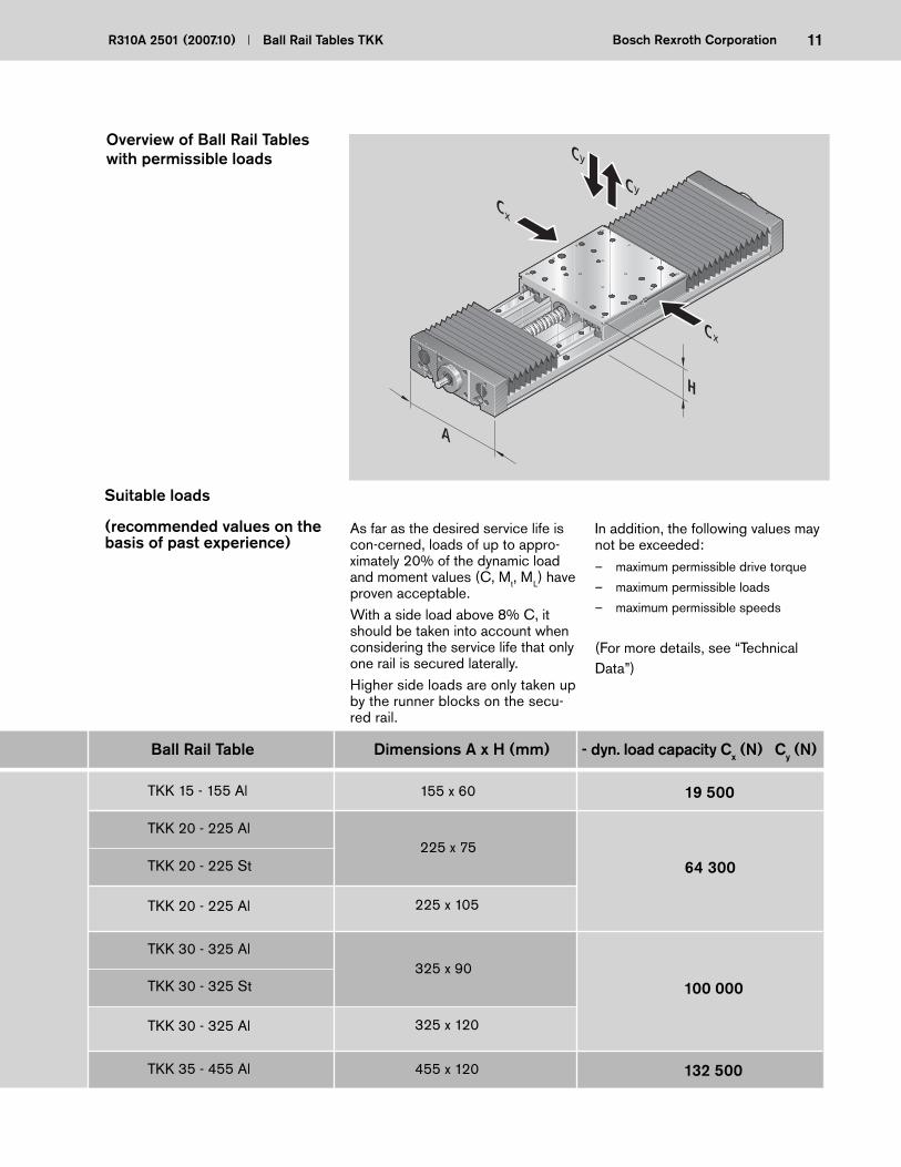
Ball Rail Table Dimensions A x H (mm) - dyn. load capacity Cx (N) Cy (N)
TKK 15 - 155 Al
TKK 20 - 225 Al
TKK 20 - 225 St
TKK 20 - 225 Al
TKK 30 - 325 Al
TKK 30 - 325 St
TKK 30 - 325 Al
TKK 35 - 455 Al
155 x 60
225 x 75
225 x 105
325 x 90
325 x 120
455 x 120
19 500
64 300
100 000
132 500
Overview of Ball Rail Tables with permissible loads
In addition, the following values may not be exceeded:– maximum permissible drive torque
– maximum permissible loads
– maximum permissible speeds
(For more details, see “TechnicalData”)
As far as the desired service life is con -cerned, loads of up to appro-ximately 20% of the dynamic load and moment values (C, Mt, ML) have proven acceptable.With a side load above 8% C, it should be taken into account when considering the service life that only one rail is secured laterally. Higher side loads are only taken up by the runner blocks on the secu-red rail.
Suitable loads
(recommended values on the basis of past experience)
A
H
Cx
Cx
Cy
yC
12 Ball Rail Tables TKK R310A 2501 (2007.10)Bosch Rexroth Corporation
1
3
2
4
56
7
910
11
14 12
8
13
1412
8
1110
15
13
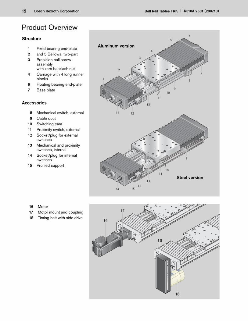
Structure
1 Fixed bearing end-plate 2 and 5 Bellows, two-part 3 Precision ball screw
assembly with zero backlash nut
4 Carriage with 4 long runner blocks
6 Floating bearing end-plate 7 Base plate
Accessories
8 Mechanical switch, external 9 Cable duct 10 Switching cam 11 Proximity switch, external 12 Socket/plug for external
switches 13 Mechanical and proximity
switches, internal 14 Socket/plug for internal
switches 15 Profi led support
16 Motor 17 Motor mount and coupling 18 Timing belt with side drive
Steel version
Aluminum version
16
17
16
18
Product Overview
13R310A 2501 (2007.10) Ball Rail Tables TKK Bosch Rexroth Corporation
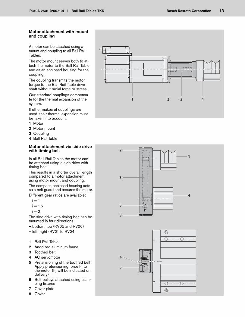
Motor attachment with mount and coupling
A motor can be attached using a mount and coupling to all Ball Rail Tables.The motor mount serves both to at-tach the motor to the Ball Rail Table and as an enclosed housing for the coupling.The coupling transmits the motor torque to the Ball Rail Table drive shaft without radial force or stress.Our standard couplings compensa-te for the thermal expansion of the system.If other makes of couplings are used, their thermal expansion must be taken into account.1 Motor2 Motor mount3 Coupling4 Ball Rail Table
Motor attachment via side drive with timing belt
In all Ball Rail Tables the motor can be attached using a side drive with timing belt.This results in a shorter overall length compared to a motor attachment using motor mount and coupling.The compact, enclosed housing acts as a belt guard and secures the motor.Different gear ratios are available: i = 1 i = 1.5 i = 2The side drive with timing belt can be mounted in four directions:– bottom, top (RV05 and RV06)– left, right (RV01 to RV04)
1 Ball Rail Table2 Anodized aluminum frame3 Toothed belt4 AC servomotor5 Pretensioning of the toothed belt:
Apply pretensioning force Fv to the motor (Fv will be indicated on delivery)
6 Belt pulleys attached using clam-ping fi xtures
7 Cover plate8 Cover
2 31 4
6
7
Fv
4
1
3
5
8
2

14 Ball Rail Tables TKK R310A 2501 (2007.10)Bosch Rexroth Corporation
Mounting Accuracy
General notes on mounting
The Aluminum Ball Rail Tables can be mounted from above or below.The Steel Ball Rail Tables can only be mounted by bolting from above. In both versions, a reference edge is built into the base plate to help align the unit. The mounting hole plugs are inclu-ded with the unit.For connection dimensions, see the rele vant dimension drawings.
Plug
Reference edge
Plug
Reference edge
Plug
Reference edge
Nut for T-slot (see accessories)
Mounting from above
Mounting from below
Mounting from above
Aluminum Ball Rail Tables
Steel Ball Rail Tables
Base plate
Base plate
Base plate
R max. 0.3
R max. 0.3
R max. 0.3
15R310A 2501 (2007.10) Ball Rail Tables TKK Bosch Rexroth Corporation
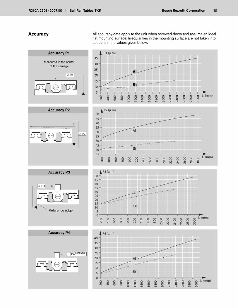
Accuracy P2
Accuracy P3
Accuracy P4
Accuracy All accuracy data apply to the unit when screwed down and assume an ideal fl at mounting surface. Irregularities in the mounting surface are not taken into account in the values given below.
P1
Measured in the center of the carriage
P1 (μ m)
5
10
15
20
25
30
35
200
400
600
800
1000
1200
1600
1800
2000
2200
2400
2600
2800
3000
L (mm)
1400
P2
P2 (μ m)
L (mm)
6560
3540455055
200
400
600
800
1000
1200
1600
1800
2000
2200
2400
2600
2800
3000
1400
707580
Accuracy P1
P3
Reference edge
P4 Longways
P3 (μ m)
L (mm)0
200
400
600
800
1000
1200
1600
1800
2000
2200
2400
2600
2800
3000
1400
504540353025201510
5
P4 (μ m)
L (mm)0
200
400
600
800
1000
1200
1600
1800
2000
2200
2400
2600
2800
3000
1400
40
35
30
25
20
15
10
5
Al
St
Al
St
Al
St
Al
St

16 Ball Rail Tables TKK R310A 2501 (2007.10)Bosch Rexroth Corporation
LT = 320 LT = 450
26000
C Mt ML FV FH
Ball Rail Table Ball Screw
Dynamic load capacity Dynamic moments Maximum loads
LT = 150 LT = 220
–
TKK 15-155 Al 25300 17000 1330 1160 2050 24000 6000
LT = 220 LT = 320
Al only
17000TKK 20-225 AlTKK 20-225 St
18800
6340 5150 9110 79200 19800
TKK 30-325AlTKK 30-325 St
79200
129960 14940 11890 20330 123200 30800
– –
–
LT = 450
29000180600 27090 24740 163200 40800
–
TKK 35-455Al
Notes on dynamic load capacities and moments
The dynamic load capacities and moments of the guideway are based on 100,000 m travel.
General system data
Technical Data
without
20 x 5
20 x 20
25 x 5
25 x 10
25 x 25
without
32 x 5
32 x 10
32 x 20
32 x 32
without
40 x 5
40 x 10
40 x 20
40 x 40
without
16 x 10
16 x 16
20 x 5
20 x 20
–
9600
9300
14300
13300
14300
13300
15900
15700
14700
–
21600
31700
19700
19500
–
29100
50000
37900
37000
Multiply values C, Mt and ML from the table by 1.26. Load ratings for the precision ball screw assembly comply with DIN 69051.
Guideway Ball Fixed screw bearing
d0 x P (N) (N) (N) (Nm) (Nm) (Nm) (N)
However, a travel of just 50,000 m is often taken as a basis. If this is the case, for comparison purposes:
17R310A 2501 (2007.10) Ball Rail Tables TKK Bosch Rexroth Corporation
0.048 · L + mb - 1
0.054 · L + mb + 5
LT = 320 LT = 450
xxy
yLT
kg
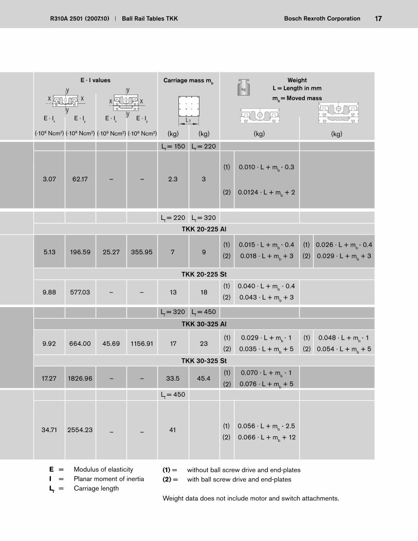
E · I values WeightL = Length in mm
mb = Moved mass
LT = 220LT = 150
E · Ix E · Iy
(·108 Ncm2) (·108 Ncm2) (kg) (kg)
0.010 · L + mb - 0.3
0.0124 · L + mb + 2
3.07 62.17 – – 2.3 3
TKK 20-225 St
5.13 196.59 25.27 355.95 7 9
9.88 577.03 – – 13 18
0.015 · L + mb - 0.4
0.018 · L + mb + 3
0.026 · L + mb - 0.4
0.029 · L + mb + 3
0.040 · L + mb - 0.4
0.043 · L + mb + 3
LT = 220 LT = 320
9.92 664.00 45.69 1156.91 17 23
17.27 1826.96 – – 33.5 45.4
0.029 · L + mb - 1
0.035 · L + mb + 5
0.070 · L + mb - 1
0.076 · L + mb + 5
(kg) (kg)
LT = 450
34.71 2554.23 – – 41 0.056 · L + mb - 2.5
0.066 · L + mb + 12
E = Modulus of elasticityI = Planar moment of inertiaLT = Carriage length
(1) = without ball screw drive and end-plates(2) = with ball screw drive and end-plates
Weight data does not include motor and switch attachments.
(1)
(2)
(1)
(2)
(1)
(2)
(1)
(2)
(1)
(2)
(1)
(2)
(1)
(2)
(1)
(2)
Carriage mass mb
TKK 20-225 Al
xxy
yE · Ix E · Iy
TKK 30-325 St
TKK 30-325 Al
(·108 Ncm2) (·108 Ncm2)

18 Ball Rail Tables TKK R310A 2501 (2007.10)Bosch Rexroth Corporation
Technical Data
Ball screw diam.Table
Reduction factor f for version with ball screw drive without bellows
fL (mm)
TKK 15-155
TKK 20-225
TKK 30-325
TKK 35-455
16
20
20
25
32
40
< 820
> 820
< 940
> 940
< 940
> 940
< 1180
> 1180
< 1580
> 1580
< 1900
> 1900
1.0
0.83
1.0
0.83
1.0
0.87
1.0
0.87
1.0
0.89
1.0
0.91
Permissible speed
Ball Rail Table
Permissible speed vper
(m/min)
180 m/min*)without drive
without bellows
Example: for TKK 30-325 Al with ball screw drive 32 x 32 but without bellows, with L = 1980 mmPermissible speed: vper = f · v = 0.89 · 57 m/min vper = 50.73 m/min(where v = 57 m/min from graph and f = 0.89 from table)
without drive
with bellows
with drive
with bellowssee graphs
100 m/min
*) Speeds up to 300 m/min are possible, but service life is limited by increased wear of the plastic compo-nents in the ball rail systems. Tests have shown distances of 50 to 100 · 105 m without failure.
with drivewithout bellows
f · vpervper: see graphs
f: see table
When selecting the motor, take account of the permissible speed of the Ball Rail Table or the selected ball screw drive.
01020
30405060
70
80 20 x 20
16 x 16
16 x 100
20 x 5
220
340
460
580
700
820
940
1060
1180
1300
1420
1540
1660
1780
1900
2020
2140
2260
2380
2500
2620
2740
2860
vper (m/min)
L (mm)
TKK 15-155 Al
vper (m/min)
0
10
20
30
40
50
60
70
8028
040
052
064
076
088
010
0011
2012
4013
6014
8016
0017
2018
4019
6020
8022
0023
2024
4025
6026
8028
00
25x25
25x10
20x5
20x20
2860
25x5
L (mm)
Al only TKK 20-225 Al
TKK 20-225 St
vper (m/min)
0
10
20
30
40
50
60
70
80
380
540
700
860
1020
1180
1340
1500
1660
1820
1980
2140
2300
2460
2620
2780
32x32
32x20
32x10
32x5
L (mm)
90
100TKK 30-325 Al
TKK 30-325 St
vper (m/min)
01020304050607080
540
700
860
1020
1180
1340
1500
1660
1820
1980
2140
2300
2460
2620
2780
40 x 40
40 x 20
40 x 10
40 x 5
L (mm)
90TKK 35-455 Al

19R310A 2501 (2007.10) Ball Rail Tables TKK Bosch Rexroth Corporation
Permissible drive torque,Fixed bearing endFor motor attachment via motor mount and coupling.
per
0
5
10
15
20
25
30
20 x 20
25 x 25
25 x10
20 x 5
25 x 5
L (mm)
280
400
520
640
760
880
1000
1120
1240
1360
1480
1600
1720
1840
1960
2080
2200
2320
2440
2560
2680
2800
M (Nm)
per
05
101520
253035
4045
380
540
700
860
1020
1180
1340
1500
1660
1820
1980
2140
2300
2460
2620
2780
32 x 10
32 x 32
32 x 20
32 x 5
L (mm)
M (Nm)
per
0
20
40
60
80
100
120
140
160
540
700
860
1020
1180
1340
1500
1660
1820
1980
2140
2300
2460
2620
2780
40 x 10
40 x 40
40 x 20
40 x 5
L (mm)
M (Nm)
The values of Mper shown apply under the following conditions: – Horizontal operation – Ball screw drive journal
without keyway – No radial load on the ball
screw drive journal – Ball rail table with
polyurethane bellows
For the permissible torque with a motor attached using side drive with timing belt, see “Timing belt side drive, Floating bearing end”.
Al only
Take account of the rated torque of the coupling used!
Ball screw journal with keywayDue to notch effect and the reduction of the effective diameter, observe the follow-ing maximum values for the drive torque!
Ball Rail Table
15-155
20-225
30-325
35-455
Mper (Nm)
4.5
18
76
4.5 (Ball screw dia. 20)11 (Ball screw dia. 25)
TKK 30-325 AlTKK 30-325 St
TKK 20-225 AlTKK 20-225 St
TKK 35-455 AlWhen comparing the graph and table, the lower of the two values applies in each case!
Example:TKK 15-155, ball screw 20x5, length 1060 mm.Drive torque Mper from graph:~ 2.7 NmMaximum permissible drive torque as per table: 4.5 NmDrive torque for sizing: 2.7 Nm
per
0
1
2
3
4
5
6
7
8
220
340
460
580
700
820
940
1060
1180
1300
1420
1540
1660
1780
1900
2020
2140
2260
2380
2500
2620
2740
2860 L (mm)
20 x 20
16 x 16
16 x 10
20 x 5
M (Nm) TKK 15-155 Al

20 Ball Rail Tables TKK R310A 2501 (2007.10)Bosch Rexroth Corporation
Drive data of the side drive with timing belt, Floating bearing end for motor attachment via side drive with timing belt
Technical Data
MKD 41B, MMD 082A
51 x 88
0.4
Permissible torque up to length L = … at (1)
Reduced mass moment of inertia at
(10-6 kgm2)(10-6 kgm2)
i = 1.5i = 1
16 AT516 AT5
i = 1.5
16 AT5
i = 1
16 AT5
(Nm)(Nm)(mm)
MRvL MRv JRv JRvBall screwBall Rail Table
Motor type
Overall dimensions (mm)
Friction moment MRRv (Nm)
Reduction i = …
Belt type
MHD 71A
66 x 116
0.45
Permissible torque up to
length L = … at (1)
Reduced mass
moment of inertia at
(10-6 kgm2)(10-6 kgm2)
i = 2i = 1
25 AT525 AT5
i = 2
25 AT5
i = 1
25 AT5
(Nm)(Nm)(mm)
MRvL MRv JRv JRv
16 x10
16 x16
20 x 5
20 x 20
TKK 15-15
20 x 5
20 x 20
25 x 5
25 x 10
25 x 25
TKK 20-225
TKK 30-325
40 x 5
40 x 10
40 x 20
40 x 40
TKK 35-455
Technical data AC servomotors
MRv … Permissible system torque with side drive with timing belt on the motor journal (motor torque not taken into account)MRRv … Friction moment, side drive with timing belt on the motor journalJRv … Reduced mass moment of inertia, side drive with timing belti … Reduction, side drive with timing belt(1) … Please ask if you wish to know the permissible torque for longer lengths
Motor
170 + 16
2.2
4.65
2.7
Maximum effective rotary speed nM (1/min)
Rated torque MMN (Nm)
Maximum torque MMmax (Nm)
Mass moment of inertia JM + JBr (10-6 kgm2)
Braking torque MBr (Nm)
Load with brake mBr (kg)
MKD 71B-061
870 + 38
5
9.42
8
d0 x P
1180
1420
1420
2260
1480
2200
2320
2860
2860
9.6
9.6
9.6
9.6
9.6
9.6
9.6
9.6
9.6
6.4
6.4
6.4
6.4
6.4
6.4
6.4
6.4
6.4
260
270
91
94
1060
1300
1420
1540
1480
1600
1960
2320
2860
11.6
11.6
10.0
19.6
10.0
19.6
14.0
19.6
19.6
5.8
5.8
5.0
9.8
5.0
9.8
7.0
9.8
9.8
32 x 5
32 x 10
32 x 20
32 x 32
2860
2860
2860
2860
19.0
19.0
19.0
19.0
9.5
9.5
9.5
9.5
1420
1420
230
230
1440 240
MKD 41B-144
133 + 8
2.4
3.7
2.4
MMD 082A MHD 71A-061
440 + 72
5
6.6
3.5
21R310A 2501 (2007.10) Ball Rail Tables TKK Bosch Rexroth Corporation
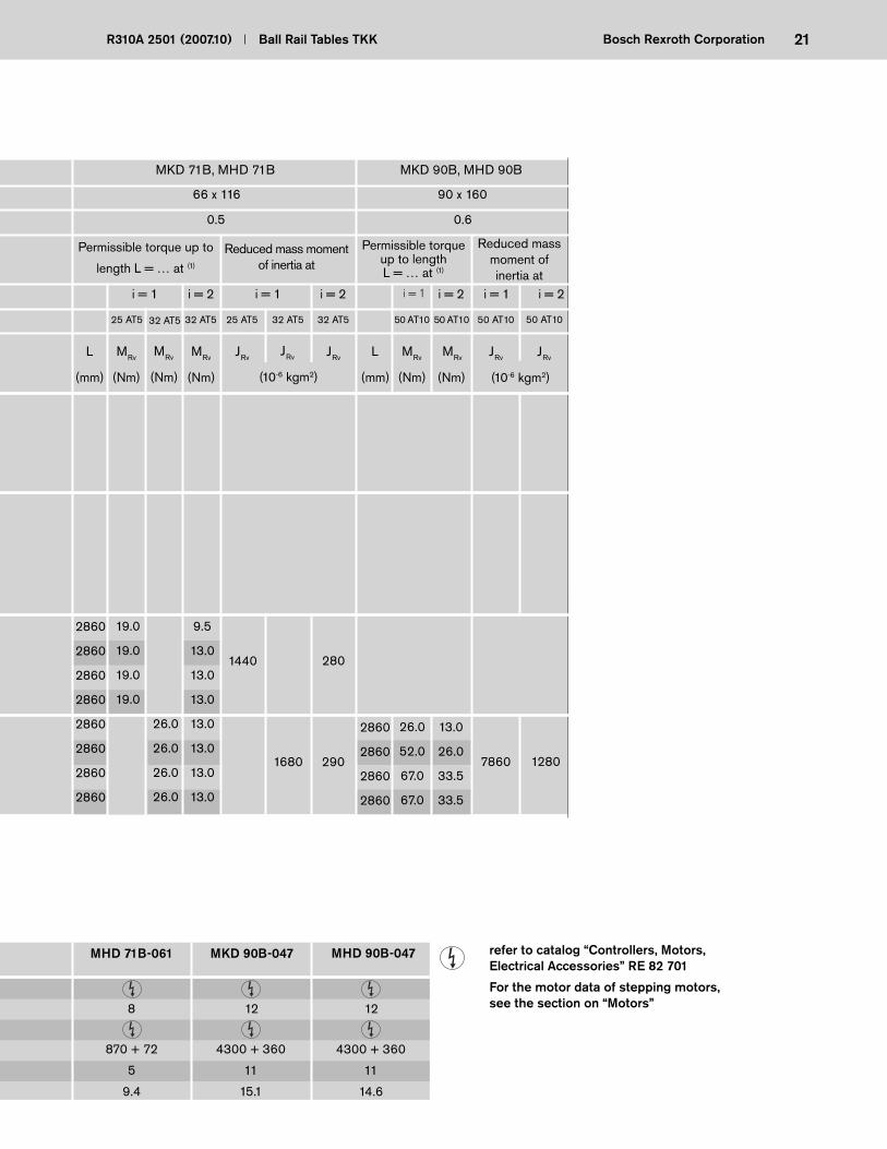
MKD 71B, MHD 71B
66 x 116
0.5
Permissible torque up to
length L = … at (1)
Reduced mass moment of inertia at
i = 2i = 1
32 AT525 AT5
i = 2
32 AT5
i = 1
25 AT5
(Nm)(Nm)(mm)
MRvL MRv JRv JRv
MKD 90B, MHD 90B
90 x 160
0.6
Permissible torque up to length L = … at (1)
Reduced mass moment of inertia at
i = 2i = 1
50 AT1050 AT10
i = 2i = 1
50 AT10
(Nm)(Nm)(mm)
MRvL MRv JRv JRv
870 + 72
5
9.4
8
4300 + 360
11
15.1
12
MHD 71B-061 MKD 90B-047
reduziertes Massenträg-heitsmoment bei
i = 1,5i = 1
16 AT516 AT5
JRv JRv
MMD 082A
51 x 88
0,4
zulässiges Drehmo-ment bis Länge
L = … bei (1)
i = 1,5
16 AT5
i = 1
16 AT5
(Nm)(Nm)(mm)
MRvL MRv
MHD 90B-047
32 AT5
(Nm)
MRv
50 AT10
2860
2860
2860
2860
2860
2860
2860
2860
19.0
19.0
19.0
19.0
9.5
13.0
13.0
13.0
13.0
13.0
13.0
13.0
1440 280
26.0
26.0
26.0
26.0
(10-6 kgm2)
32 AT5
JRv
(10-6 kgm2) (10-6 kgm2)
1680 290
2860
2860
2860
2860
26.0
52.0
67.0
67.0
13.0
26.0
33.5
33.5
7860 1280
4300 + 360
11
14.6
12
refer to catalog “Controllers, Motors, Electrical Accessories” RE 82 701
For the motor data of stepping motors, see the section on “Motors”
22 Ball Rail Tables TKK R310A 2501 (2007.10)Bosch Rexroth Corporation
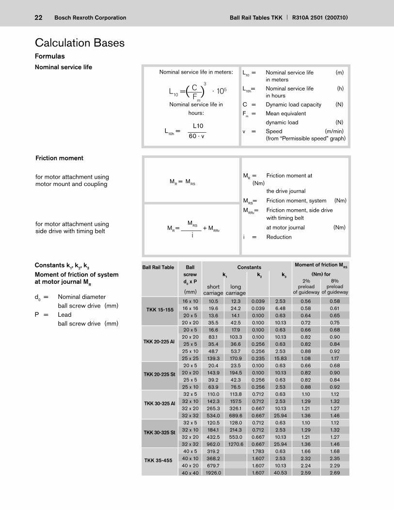
Calculation Bases
Nominal service life in meters:
Nominal service life in hours:
L10 = · 105
FormulasNominal service life
L10 = Nominal service life (m) in meters
L10h= Nominal service life (h) in hours
C = Dynamic load capacity (N)
Fm = Mean equivalent
dynamic load (N)
v = Speed (m/min) (from “Permissible speed” graph)
L10h =
) CFm
60 · v
L10
Friction moment
MR = Friction moment at (Nm) the drive journal
MRS= Friction moment, system (Nm)
MRRv= Friction moment, side drive with timing belt
at motor journal (Nm)
i = Reduction
for motor attachment usingmotor mount and coupling
for motor attachment using side drive with timing belt
MR = MRS
MR = + MRRv i
MRS
3
Constants k1, k2, k3
Moment of friction of system at motor journal MR
TKK 15-155
TKK 20-225 Al
TKK 30-325 Al
TKK 30-325 St
16 x 1016 x 1620 x 5
20 x 2020 x 5
20 x 2025 x 525 x 1025 x 2520 x 5
20 x 2025 x 525 x 1032 x 532 x 1032 x 2032 x 3232 x 532 x 1032 x 2032 x 3240 x 540 x 1040 x 2040 x 40
Ball Rail Table Ball screwd0 x P
Constants
10.519.613.635.516.683.135.448.7
139.320.4143.939.263.9110.0142.3265.3534.0120.5184.1432.5962.0319.2368.2679.7
1926.0
12.324.214.142.517.9
103.336.653.7170.923.5194.542.376.5113.8157.5326.1689.6128.0214.3553.01270.6
shortcarriage
longcarriage
k1 k2 k3
0.0390.0390.1000.1000.1000.1000.2560.2560.2350.1000.1000.2560.2560.7120.7120.6670.6670.7120.7120.6670.6671.7831.6071.6071.607
2.536.480.6310.130.6310.130.632.5315.830.6310.130.632.530.632.5310.1325.940.632.5310.1325.940.632.5310.1340.53
Moment of friction MRS
(Nm) for2%
preloadof guideway
8%preload
of guideway(mm)
TKK 20-225 St
TKK 35-455
0.560.580.640.720.660.820.820.881.080.660.820.820.881.101.291.211.361.101.291.211.361.662.322.242.59
0.580.610.650.750.680.900.840.921.170.680.900.840.921.121.321.271.461.121.321.271.461.682.352.292.69
(
d0 = Nominal diameter ball screw drive (mm)P = Lead ball screw drive (mm)
23R310A 2501 (2007.10) Ball Rail Tables TKK Bosch Rexroth Corporation
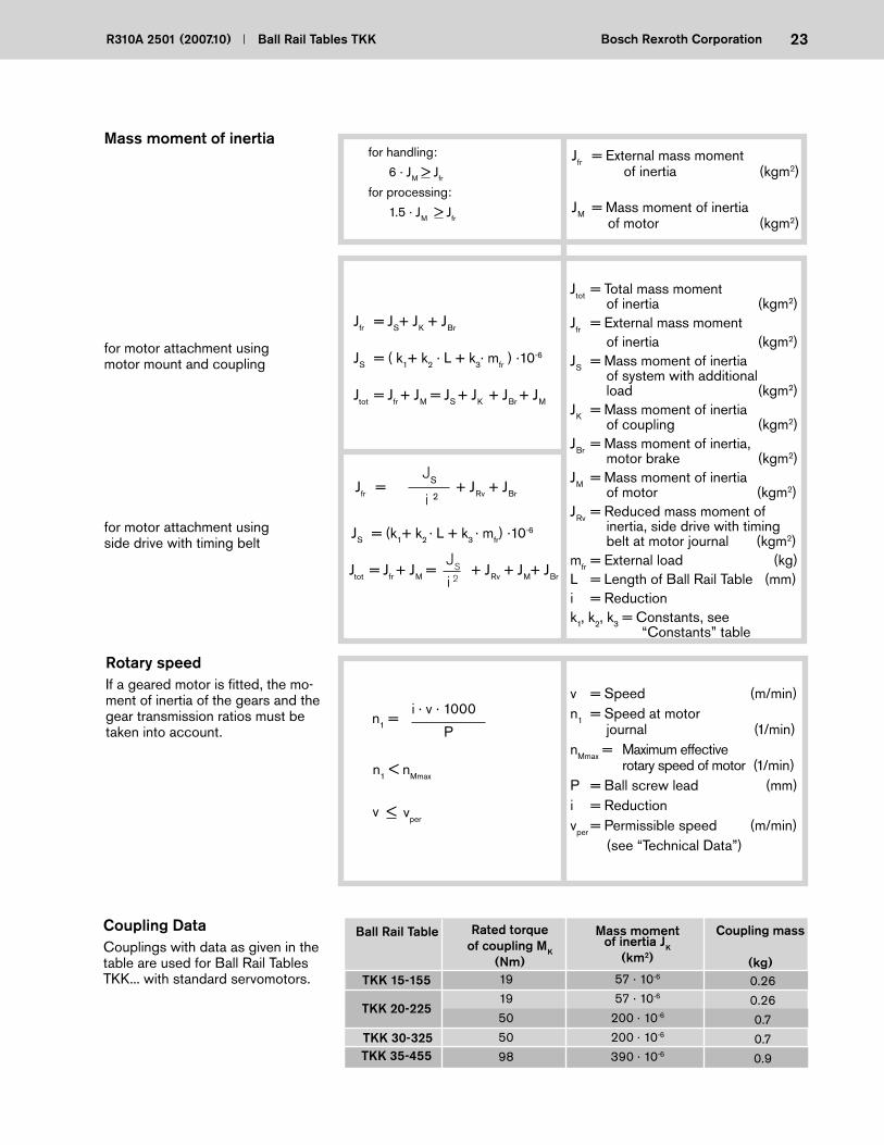
Mass moment of inertiafor handling:
6 · JM > Jfr
for processing:
1.5 · JM > Jfr
Jfr = External mass moment of inertia (kgm2)
JM = Mass moment of inertia of motor (kgm2)
for motor attachment using motor mount and coupling
Jfr = JS+ JK + JBr
Jtot = Jfr + JM = JS + JK + JBr + JM
JS = (k1+ k2 · L + k3 · mfr) ·10-6
Jtot = Jfr + JM = + JRv + JM+ JBr
for motor attachment using side drive with timing belt
JS
i 2
Rotary speedIf a geared motor is fi tted, the mo-ment of inertia of the gears and the gear trans mission ratios must be taken into account.
v = Speed (m/min)n1 = Speed at motor
journal (1/min)nMmax = Maximum effective
rotary speed of motor (1/min)P = Ball screw lead (mm)i = Reductionvper = Permissible speed (m/min) (see “Technical Data”)
i 2
i · v · 1000n1 =
P
v <
n1 < nMmax
vper
JS
Coupling DataCouplings with data as given in the table are used for Ball Rail Tables TKK... with standard servomotors.
Jtot = Total mass moment of inertia (kgm2)
Jfr = External mass moment of inertia (kgm2)JS = Mass moment of inertia
of system with additional load (kgm2)
JK = Mass moment of inertia of coupling (kgm2)
JBr = Mass moment of inertia, motor brake (kgm2)
JM = Mass moment of inertia of motor (kgm2)
JRv = Reduced mass moment of inertia, side drive with timing belt at motor journal (kgm2)
mfr = External load (kg)L = Length of Ball Rail Table (mm)i = Reduction k1, k2, k3 = Constants, see
“Constants” table
Jfr = + JRv + JBr
JS = ( k1+ k2 · L + k3· mfr ) ·10-6
Ball Rail Table Rated torqueof coupling MK
(Nm)
Mass moment of inertia JK
(km2)
Coupling mass
(kg)TKK 15-155
TKK 20-225
TKK 30-325TKK 35-455
1919505098
57 · 10-6
57 · 10-6
200 · 10-6
200 · 10-6
390 · 10-6
0.260.260.70.70.9
24 Ball Rail Tables TKK R310A 2501 (2007.10)Bosch Rexroth Corporation
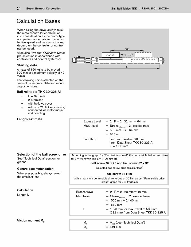
Selection of the ball screw drive
L
Length estimateExcess travel = 2 · P = 2 · 32 mm = 64 mmMax. travel = Strokeeffective + 2 · excess travel = 500 mm + 2 · 64 mm = 628 m
Starting dataA mass of 150 kg is to be moved 500 mm at a maximum velocity of 40 m/min.The following unit is selected on the basis of its technical data and moun-ting dimensions:
Ball rail table TKK 30-325 Al – LT = 320 mm – 2% preload – with bellows cover – with size 71 AC servomotor,
connected via motor mount and coupling
When sizing the drive, always take the motor/controller combination into con sideration as the motor type and per for mance data (e.g. max. ef-fective speed and maximum torque) depend on the controller or control system used. (See also ”Product Overview, Motor pre -selection in accordance with controllers and control systems”).
According to the graph for “Permissible speed”, the permissible ball screw drives for v = 40 m/min and L = 1100 mm are:
ball screw 32 x 20 and ball screw 32 x 32Selected ball screw drive (smaller lead)
500
m=150 F = 0 N
L
See “Technical Data” section for graphs.
Length L: for max. travel = 628 mm from Data Sheet TKK 30-325 Al L = 1100 mm
ball screw 32 x 20 with a maximum permissible drive torque of 35 Nm as per “Permissible drive
torque” graph for L = 1100 mm
CalculationLength L
Excess travel = 2 · P = 2 · 20 mm = 40 mmMax. travel = Strokeeffective + 2 · excess travel = 500 mm + 2 · 40 mm = 580 mm L = 1020 mm for max. travel of 580 mm
(582 mm) from Data Sheet TKK 30-325 Al
General recommendation:Wherever possible, always select the smallest lead.
Friction moment MR MR = MRS (see “Technical Data”)MR = 1.21 Nm
Calculation Bases
25R310A 2501 (2007.10) Ball Rail Tables TKK Bosch Rexroth Corporation
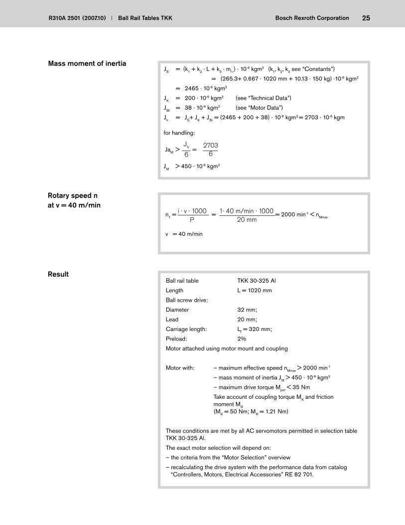
v = 40 m/min
Pi · v · 1000
20 mm
Rotary speed nat v = 40 m/min
ResultBall rail table TKK 30-325 Al
Length L = 1020 mm
Ball screw drive:
Diameter 32 mm;
Lead 20 mm;
Carriage length: LT = 320 mm;
Preload: 2%
Motor attached using motor mount and coupling
Motor with: – maximum effective speed nMmax > 2000 min-1
– mass moment of inertia JM > 450 · 10-6 kgm2
– maximum drive torque Mper < 35 Nm
Take account of coupling torque MK and friction moment MR (MK = 50 Nm; MR = 1.21 Nm)
These conditions are met by all AC servomotors permitted in selection table TKK 30-325 Al.
The exact motor selection will depend on:
– the criteria from the “Motor Selection” overview
– recalculating the drive system with the performance data from catalog “Controllers, Motors, Electrical Accessories” RE 82 701.
Mass moment of inertiaJS = (k1 + k2 · L + k3 · mf r) · 10-6 kgm2 (k1, k2, k3 see “Constants”)
= (265.3+ 0.667 · 1020 mm + 10.13 · 150 kg) ·10-6 kgm2
= 2465 · 10-6 kgm2
JK = 200 · 10-6 kgm2 (see “Technical Data”)
JBr = 38 · 10-6 kgm2 (see “Motor Data”)
Jfr = JS+ JK + JBr = (2465 + 200 + 38) · 10-6 kgm2 = 2703 · 10-6 kgm
Jfr
62703
6
n1 = = = 2000 min-1 < nMmax 1· 40 m/min · 1000
for handling:
JaM > =
JM > 450 · 10-6 kgm2
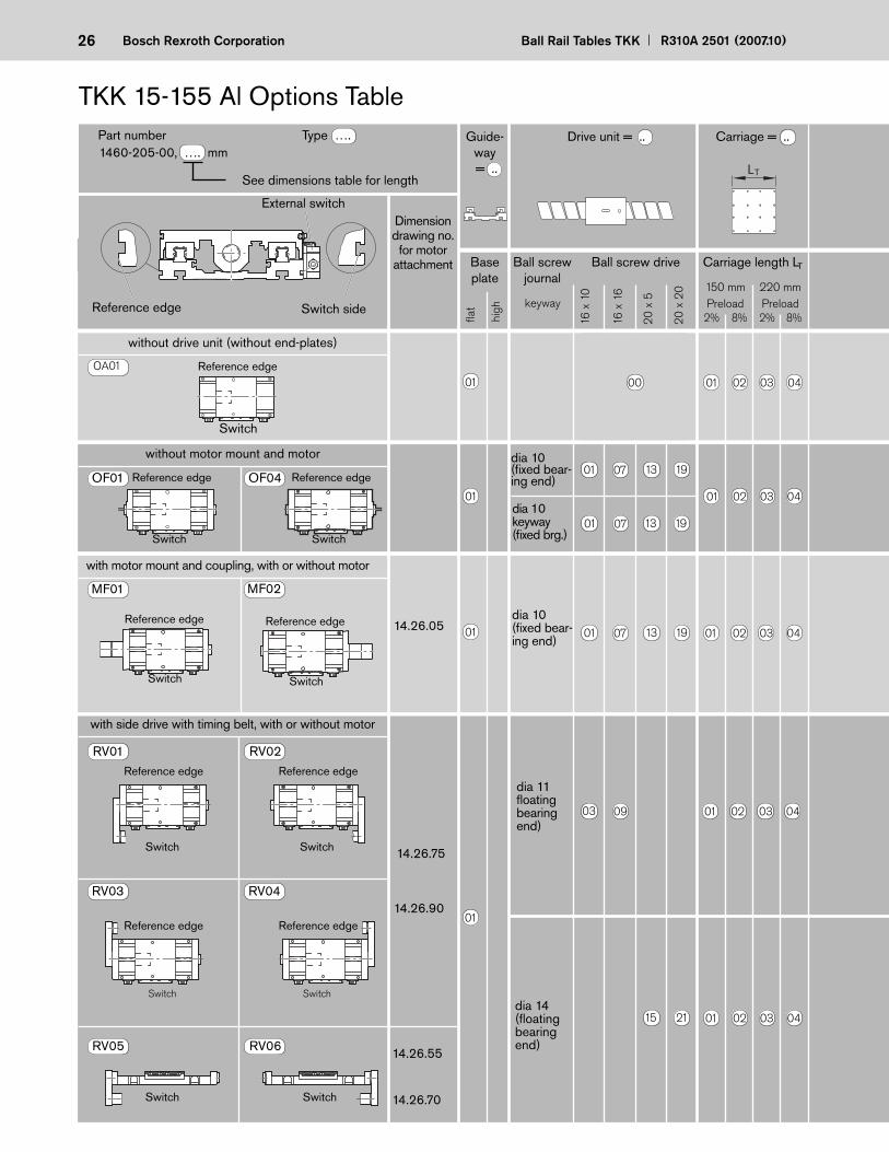
26 Ball Rail Tables TKK R310A 2501 (2007.10)Bosch Rexroth Corporation
dia 11 fl oating bear ing end)
dia 14 (fl oating bear ing end)
14.26.75
14.26.90
14.26.55
14.26.70
RV01 RV02
RV05 RV06
RV03 RV04
with side drive with timing belt, with or without motor
Reference edge
Switch
Reference edge
Switch
Reference edge
Switch
Reference edge
Switch
Switch Switch
TKK 15-155 Al Options Table
See dimensions table for length
Dimension drawing no. for motor
attachment Ball screw journal
Ball screw drive
16 x
10
16 x
16
20
x 5
20
x 2
0
without drive unit (without end-plates)
without motor mount and motor
with motor mount and coupling, with or without motor
dia 10 (fi xed bear-ing end)
14.26.05
OA01
MF01 MF02
OF01 OF04
1460-205-00, …. mm Drive unit = ..
Reference edge Switch side
External switch
Baseplate
Part number Type ….
8%2% 8%2%Preload
fl at
high
Guide-way = ..
Carriage = ..
Carriage length LT
220 mm150 mmPreload
Reference edge
Switch
Reference edge
Switch
Reference edge
Switch
Reference edge
Switch
Reference edge
Switch
dia 10 keyway (fi xed brg.)
keyway
LT
dia 10 (fi xed bear-ing end)
01 07 13 19 01 02 03 04
03 09 01 02 03 04
00 01 02 03 0401
01
01
01
15 21 01 02 03 04
01 07 13 19
01 02 03 04
01 07 13 19

27R310A 2501 (2007.10) Ball Rail Tables TKK Bosch Rexroth Corporation
1
1
2
1
1
2
without
without
MKD 41B
MHD71A-061
Mounting direction as per
diagram
Motor type
Polyurethane bellows
with -out
with with -out
withi =
1 MF01-MF02
Switch typePos. and directionSwitch activation point in mm
External switching
cam
External socket-
plug (loose)
External switch
PNP NO
PNP NC
Mechanical
Cable duct (loose)
Cable duct
Motor attachment = ..
Motor = .. Position mea-suring system = ..
Documen- tation = ..
1st switch = ..-. ± ….. mm2nd switch = ..-. ± ….. mm3rd switch = ..-. ± ….. mmCable duct = .. - . .... mm
Socket-plug = ..Switching cam = ..
OF01-OF04
15 -A ±….
13 -A ±….
11 -A ±….
TypeLength in mm
upon request
MKD 41B
20 - X....
without switchwithout cable duct
Cover = ..
MMD 082A
Reference edge
Direction
Sta
ndar
dre
port
Spe
cial
re
port
Friction moment
Lead deviation
Sequence accuracy
Positioning accuracy
L/2
– 0 +
OA01 without
Please check whether the selected combination is a permissible one (load capacities, moments, maximum speeds, motor data, etc.)!
without
MMD 082A
without
MKD 41B without
MHD71A-061
without
MMD 082A
1
1.5
1
without
without
Switch
1.5
1.5
1.5
Glass scale
41424344293031325354
55
56
45
46
47
48
37
38
39
40
49
50
51
52
RV01-RV04
RV05-RV06
RV01-RV04
RV05-RV06
RV01-RV04
RV05-RV06
RV01-RV04
RV05-RV06
RV01-RV04
RV05-RV06
RV01-RV04
RV05-RV06
RV01-RV04
RV05-RV06
RV01-RV04
RV05-RV06
RV01-RV04
RV05-RV06
RV01-RV04
RV05-RV06
RV01-RV04
RV05-RV06
RV01-RV04
RV05-RV06
00
10
00
60
02
06
0000
00 00
10
01 00
00
61
00
60
00
10
00
61
00
60
0000 0000 02
03
03
04
16
1705
upon request

28 Ball Rail Tables TKK R310A 2501 (2007.10)Bosch Rexroth Corporation
Length Counterbored Max. travel mounting for carriage length* hole spacing with bellows without bellows L (mm) F - G x 120 - F 150* 220* 150* 220*
Typ
ID-N
rD
atumD
eutsche Star G
mbH
97419 Schw
einfurt
33
30 6024
h=1.8
3P9 27
203
27ø10
h7
F 133542
1335
G x 120L
F
ø 55
-0.0
3
12065 54.5
150 (220)
19.5
26
66
ø10
h7
ø 55
-0.0
3
+2.
0
66+
2.0
One-point lubrication via
funnel-type lube nipples
DV1 - M6 on both sides
Max. travel
Effective stroke
External plug for external switch
Mechanical switch
Induction-type proximity switch
Switching cam Mechanical switch
20 - 13 x 120 - 20 1155 1097 1440 1370 50 - 13 x 120 - 50 1204 1146 1500 1430 20 - 14 x 120 - 20 1254 1196 1560 1490 50 - 14 x 120 - 50 1303 1245 1620 1550 20 - 15 x 120 - 20 1353 1295 1680 1610 50 - 15 x 120 - 50 1402 1344 1740 1670 20 - 16 x 120 - 20 1451 1394 1800 1730 50 - 16 x 120 - 50 1501 1443 1860 1790 20 - 17 x 120 - 20 1550 1492 1920 1850 50 - 17 x 120 - 50 1600 1542 1980 1910 20 - 18 x 120 - 20 1649 1591 2040 1970 50 - 18 x 120 - 50 1699 1641 2100 2030 20 - 19 x 120 - 20 1748 1690 2160 2090 50 - 19 x 120 - 50 1797 1739 2220 2150 20 - 20 x 120 - 20 1847 1789 2280 2210 50 - 20 x 120 - 50 1896 1838 2340 2270 20 - 21 x 120 - 20 1946 1888 2400 2330 50 - 21 x 120 - 50 1995 1937 2460 2390 20 - 22 x 120 - 20 2045 1987 2520 2450 50 - 22 x 120 - 50 2094 2036 2580 2510 20 - 23 x 120 - 20 2143 2085 2640 2570 50 - 23 x 120 - 50 2193 2135 2700 2630
Floating bearing end-plate
TKK 15-155 Al Dimension Drawings
Length Counterbored Max. travel mounting for carriage length* hole spacing with bellows without bellows L (mm) F - G x 120 - F 150* 220* 150* 220*
220 280 340 400 460 520 580 640 700 760 820 880 940 1000 1060 1120 1180 1240 1300 1360 1420 1480 1540
1600 1660 1720 1780 1840 1900 1960 2020 2080 2140 2200 2260 2320 2380 2440 2500 2560 2620 2680 2740 2800 2860
50 - 1 x 120 - 50 - - 60 - 20 - 2 x 120 - 20 68 - 120 - 50 - 2 x 120 - 50 117 59 180 110 20 - 3 x 120 - 20 166 109 240 170 50 - 3 x 120 - 50 216 158 300 230 20 - 4 x 120 - 20 265 207 360 290 50 - 4 x 120 - 50 315 257 420 350 20 - 5 x 120 - 20 364 306 480 410 50 - 5 x 120 - 50 414 356 540 470 20 - 6 x 120 - 20 463 405 600 530 50 - 6 x 120 - 50 512 454 660 590 20 - 7 x 120 - 20 562 504 720 650 50 - 7 x 120 - 50 611 553 780 710 20 - 8 x 120 - 20 661 603 840 770 50 - 8 x 120 - 50 710 652 900 830 20 - 9 x 120 - 20 759 702 960 890 50 - 9 x 120 - 50 809 751 1020 950 20 - 10 x 120 - 20 858 800 1080 1010 50 - 10 x 120 - 50 908 850 1140 1070 20 - 11 x 120 - 20 957 899 1200 1130 50 - 11 x 120 - 50 1007 949 1260 1190 20 - 12 x 120 - 20 1056 998 1320 1250 50 - 12 x 120 - 50 1105 1048 1380 1310
2Excess travel Excess travel
Fixed bearing end-plate
2Max. travel
Effective stroke2
2

29R310A 2501 (2007.10) Ball Rail Tables TKK Bosch Rexroth Corporation
153
105ø6.6W
135155 33
Slot ?0.5H13
60
213033
8266
50
11.5
14.5
+0.
36.
5
+0.
5
8 +0.3
+0.5
R10 1)
Reference edge
Front view
Detail W
3545
35
35 45 35 17.5150
17.5
95153
1319.5 9.5
52.5 35 45 35 52.5220
207.5
207.5
165
153
1935
4519
95
35
131
2424
105
13144.5 44.5
Mounting hole pattern for carriage length LT = 150
M6-min. 8 deep (12x)
M6-min. 8 deep (20x)
Distance between switch activation points of two switches
Switch position For switch combination Min. spacing (mm)
mechanical - mechanical 60 external mechanical - proximity 45 proximity - proximity 12.5
Effective stroke
Maximum switch activation point = 0.5 · max. travel - excess travel
Maximum switch activation point
For safe operation, the excess travel must be longer than the braking di-stance. The acceleration travel can be taken as guide line value for the braking distance. In most cases, 2x the ball screw lead (P) will be suffi cient.
Example for P = 20 mm:Excess travel (braking distance) 40 mm
Recommended standard confi guration:
– 2 mechanical switches
– 1 proximity switch
The switch activation point charac-terizes the position of the center of the carriage after travel. The zero point is at L/2.
Effective stroke = max. travel - 2 · excess travel
6 H7 - 8 deep (3x)
6 H7 - 8 deep
1) min. 25 deep (4x)
Mounting hole pattern for carriage length LT = 220
M8-18 deep in each end-plate 4x
30 Ball Rail Tables TKK R310A 2501 (2007.10)Bosch Rexroth Corporation
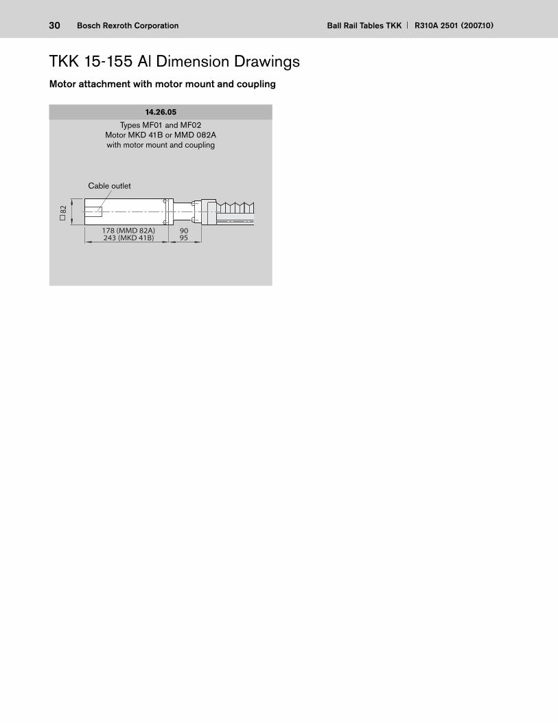
Motor attachment with motor mount and coupling
14.26.05
Types MF01 and MF02Motor MKD 41B or MMD 082Awith motor mount and coupling
243 (MKD 41B)
82
95178 (MMD 82A) 90
Cable outlet
TKK 15-155 Al Dimension Drawings
31R310A 2501 (2007.10) Ball Rail Tables TKK Bosch Rexroth Corporation
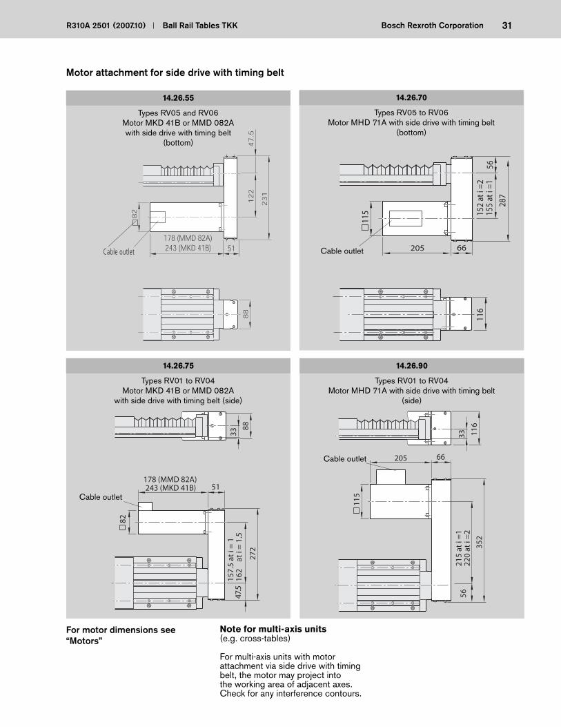
Types RV01 to RV04 Motor MKD 41B or MMD 082A
with side drive with timing belt (side)
14.26.75 14.26.90
Types RV01 to RV04 Motor MHD 71A with side drive with timing belt
(side)
Motor attachment for side drive with timing belt
Types RV05 and RV06Motor MKD 41B or MMD 082Awith side drive with timing belt
(bottom)
14.26.55 14.26.70
Types RV05 to RV06Motor MHD 71A with side drive with timing belt
(bottom)
116
152
at i
=215
5 at
i =1
205 66
115
5628
7
88
82
178 (MMD 82A)51
47
.51
22
23
1
243 (MKD 41B)Cable outlet
82
243 (MKD 41B) 51
157.
5 at
i =
116
2
at i
= 1
.5
272
47.5
33
88
178 (MMD 82A)
115
205 6621
5 at
i =
122
0 at
i =
2
352
5633 11
6
Cable outlet
Cable outlet
Cable outlet
For motor dimensions see “Motors”
Note for multi-axis units (e.g. cross-tables)
For multi-axis units with motor attachment via side drive with timing belt, the motor may project into the working area of adjacent axes. Check for any interference contours.
32 Ball Rail Tables TKK R310A 2501 (2007.10)Bosch Rexroth Corporation
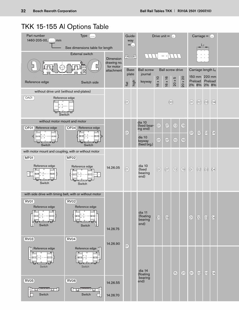
dia 11 (fl oating bear ing end)
dia 14 (fl oating bear ing end)
14.26.75
14.26.90
14.26.55
14.26.70
RV01 RV02
RV05 RV06
RV03 RV04
with side drive with timing belt, with or without motor
Reference edge
Switch
Reference edge
Switch
Reference edge
Switch
Reference edge
Switch
Switch Switch
TKK 15-155 Al Options Table
See dimensions table for length
Dimension drawing no. for motor
attachment Ball screw journal
Ball screw drive
16 x
10
16 x
16
20 x
5
20 x
20
without drive unit (without end-plates)
without motor mount and motor
with motor mount and coupling, with or without motor
dia 10 (fi xed bear ing end)
14.26.05
OA01
MF01 MF02
OF01 OF04
1460-205-00, …. mm Drive unit = ..
Reference edge Switch side
External switch
Baseplate
Part number Type ….
8%2% 8%2%Preload
fl at
high
Guide-way = ..
Carriage = ..
Carriage length LT
220 mm150 mmPreload
Reference edge
Switch
Reference edge
Switch
Reference edge
Switch
Reference edge
Switch
Reference edge
Switch
dia 10 keyway (fi xed brg.)
keyway
LT
dia 10 (fi xed bear-ing end)
01 07 13 19 01 02 03 04
03 09 01 02 03 04
00 01 02 03 0401
01
01
01
15 21 01 02 03 04
01 07 13 19
01 02 03 04
01 07 13 19

33R310A 2501 (2007.10) Ball Rail Tables TKK Bosch Rexroth Corporation
1
1
2
1
1
2
without
without
MKD 41B
MHD71A-061
Mounting direction as per
diagram
Motor type
Polyurethane bellows
with -out
with with -out
withi =
1 MF01-MF02
Switch typePos. and directionSwitch activation point in mm
External switching
cam
External socket-
plug (loose)
External switch
PNP NO
PNP NC
Mechanical
Cable duct (loose)
Cable duct
Motor attachment = ..
Motor = .. Position mea-suring system = ..
Documen- tation = ..
1st switch = ..-. ± ….. mm2nd switch = ..-. ± ….. mm3rd switch = ..-. ± ….. mmCable duct = .. - . .... mm
Socket-plug = ..Switching cam = ..
OF01-OF04
15 -A ±….
13 -A ±….
11 -A ±….
upon request
TypeLength in mm
upon request
MKD 41B
20 - X....
without switchwithout cable duct
Cover = ..
MMD 082A
Reference edge
Direction
Sta
ndar
dre
port
Spe
cial
re
port
Friction moment
Lead deviation
Sequence accuracy
Positioning accuracy
L/2
– 0 +
OA01 without
Please check whether the selected combination is a permissible one (load capacities, moments, maximum speeds, motor data, etc.)!
without
MMD 082A
without
MKD 41B without
MHD71A-061
without
MMD 082A
1
1.5
1
without
without
Switch
1.5
1.5
1.5
Glass scale
41424344293031325354
55
56
45
46
47
48
37
38
39
40
49
50
51
52
RV01-RV04
RV05-RV06
RV01-RV04
RV05-RV06
RV01-RV04
RV05-RV06
RV01-RV04
RV05-RV06
RV01-RV04
RV05-RV06
RV01-RV04
RV05-RV06
RV01-RV04
RV05-RV06
RV01-RV04
RV05-RV06
RV01-RV04
RV05-RV06
RV01-RV04
RV05-RV06
RV01-RV04
RV05-RV06
RV01-RV04
RV05-RV06
00
10
00
60
02
06
0000
00 00
10
01 00
00
61
00
60
00
10
00
61
00
60
0000 0000 02
03
03
04
16
1705
34 Ball Rail Tables TKK R310A 2501 (2007.10)Bosch Rexroth Corporation
Length Counterbored Max. travel mounting for carriage length* hole spacing with bellows w/o bellowsL (mm) F - G x 120 - F 220* 320* 220* 320*
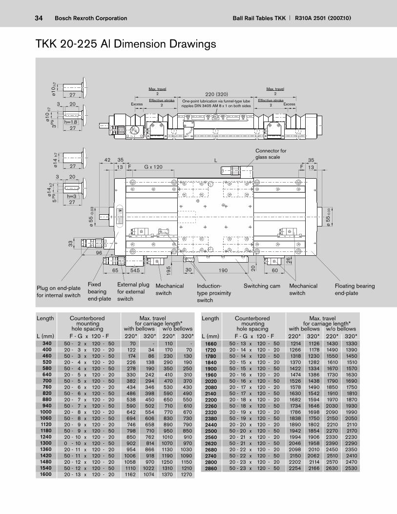
TKK 20-225 Al Dimension Drawings
Typ
ID-N
rD
atumD
eutsche Star G
mbH
97419 Schw
einfurt
h=1.8ø10
h73
P9
27
203
27ø10
h7
30 6020
ø 55
-0.0
3
F 133542
1335
G x 120L
F
ø 55
-0.0
3
19065 54.5
220 (320)
33
96
26
h=3ø14
h75
P9
27
203
27ø14
h7
19.5
One-point lubrication via funnel-type lube nipples DIN 3405 AM 8 x 1 on both sidesExcess
Effective stroke2
Effective stroke2 Excess
Max. travel2
Max. travel2
Connector for glass scale
External plug for external switch
Mechanical switch
Induction-type proximity switch
Switching cam Mechanical switch
Plug on end-plate for internal switch
Floating bearing end-plate
Fixed bearing end-plate
50 - 2 x 120 - 50 70 - 110 - 20 - 3 x 120 - 20 122 34 170 70 50 - 3 x 120 - 50 174 86 230 130 20 - 4 x 120 - 20 226 138 290 190 50 - 4 x 120 - 50 278 190 350 250 20 - 5 x 120 - 20 330 242 410 310 50 - 5 x 120 - 50 382 294 470 370 20 - 6 x 120 - 20 434 346 530 430 50 - 6 x 120 - 50 486 398 590 490 20 - 7 x 120 - 20 538 450 650 550 50 - 7 x 120 - 50 590 502 710 610 20 - 8 x 120 - 20 642 554 770 670 50 - 8 x 120 - 50 694 606 830 730 20 - 9 x 120 - 20 746 658 890 790 50 - 9 x 120 - 50 798 710 950 850 20 - 10 x 120 - 20 850 762 1010 910 0 - 10 x 120 - 50 902 814 1070 970 20 - 11 x 120 - 20 954 866 1130 1030 50 - 11 x 120 - 50 1006 918 1190 1090 20 - 12 x 120 - 20 1058 970 1250 1150 50 - 12 x 120 - 50 1110 1022 1310 1210 20 - 13 x 120 - 20 1162 1074 1370 1270
340 400 460 520 580 640 700 760 820 880 940 1000 1060 1120 1180 1240 1300 1360 1420 1480 1540 1600
1660 1720 1780 1840 1900 1960 2020 2080 2140 2200 2260 2320 2380 2440 2500 2560 2620 2680 2740 2800 2860
50 - 13 x 120 - 50 1214 1126 1430 1330 20 - 14 x 120 - 20 1266 1178 1490 1390 50 - 14 x 120 - 50 1318 1230 1550 1450 20 - 15 x 120 - 20 1370 1282 1610 1510 50 - 15 x 120 - 50 1422 1334 1670 1570 20 - 16 x 120 - 20 1474 1386 1730 1630 50 - 16 x 120 - 50 1526 1438 1790 1690 20 - 17 x 120 - 20 1578 1490 1850 1750 50 - 17 x 120 - 50 1630 1542 1910 1810 20 - 18 x 120 - 20 1682 1594 1970 1870 50 - 18 x 120 - 50 1734 1646 2030 1930 20 - 19 x 120 - 20 1786 1698 2090 1990 50 - 19 x 120 - 50 1838 1750 2150 2050 20 - 20 x 120 - 20 1890 1802 2210 2110 50 - 20 x 120 - 50 1942 1854 2270 2170 20 - 21 x 120 - 20 1994 1906 2330 2230 50 - 21 x 120 - 50 2046 1958 2390 2290 20 - 22 x 120 - 20 2098 2010 2450 2350 50 - 22 x 120 - 50 2150 2062 2510 2410 20 - 23 x 120 - 20 2202 2114 2570 2470 50 - 23 x 120 - 50 2254 2166 2630 2530
Length Counterbored Max. travel mounting for carriage length* hole spacing with bellows w/o bellowsL (mm) F - G x 120 - F 220* 320* 220* 320*
35R310A 2501 (2007.10) Ball Rail Tables TKK Bosch Rexroth Corporation
153
105ø6.6W
135155 33
Slot ?0.5H13
60
213033
8266
50
11.5
14.5
+0.
36.
5
+0.
5
8 +0.3
+0.5
R10 1)
70 60
10
27.5245
223
160
70
607060
27.5
6070
702006070 (10)10
7060
7010
223
220
160
192
320
200
Reference edge
Detail W
Front view
Mounting hole pattern for carriage length LT = 220
Mounting hole pattern for carriage length LT = 320
M8-min. 12 deep (8x)
M6-min. 9 deep (16x)
M6-min. 9 deep (16x)
M8-18 deep in each end-plate 4x
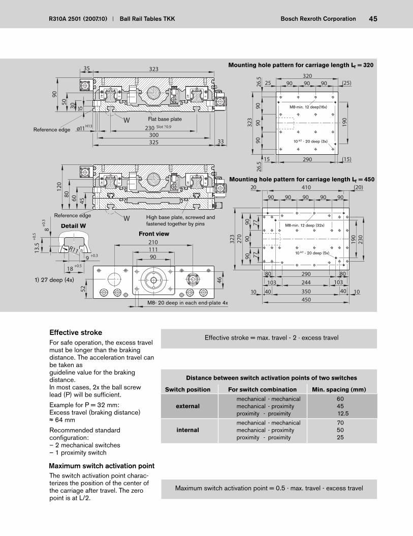
Distance between switch activation points of two switches
Switch position For switch combination Min. spacing (mm)
mechanical - mechanical 60 external mechanical - proximity 45 proximity - proximity 12.5
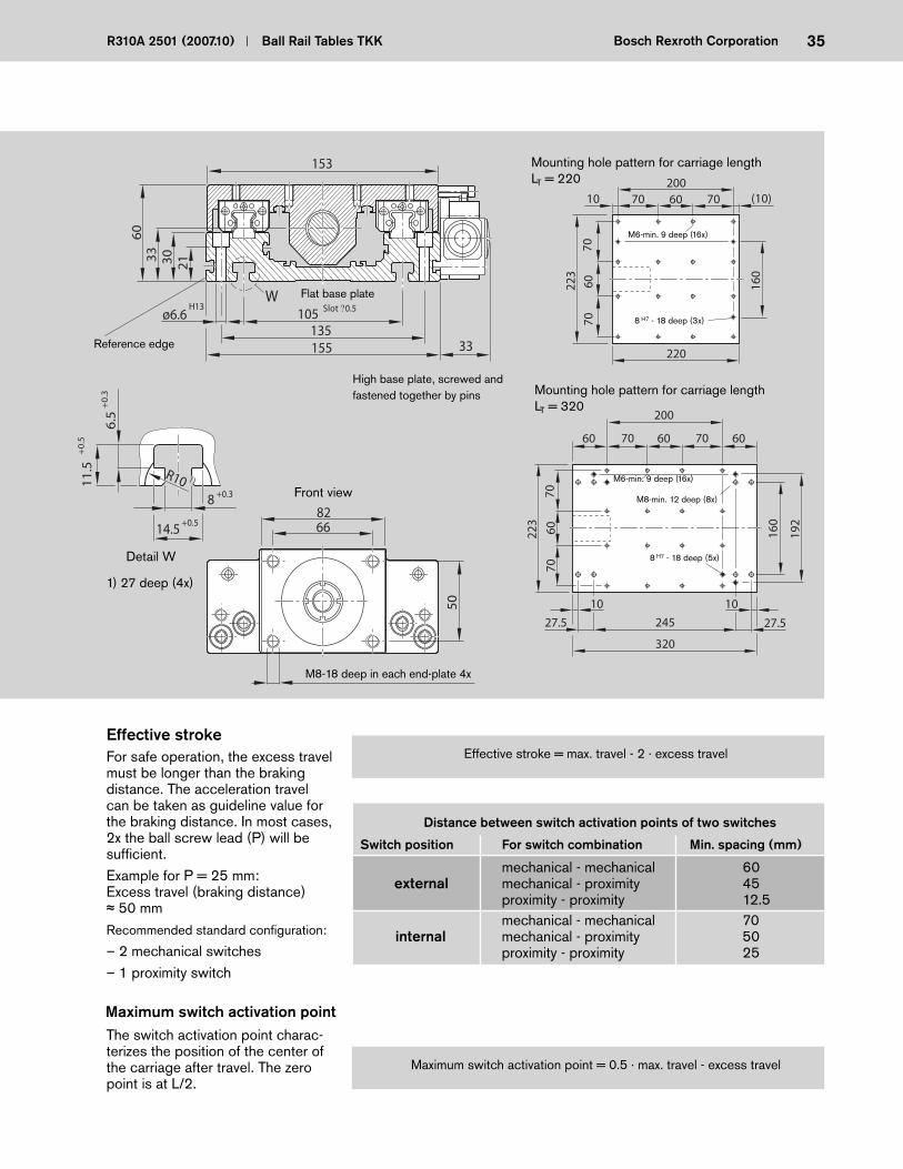
Effective stroke = max. travel - 2 · excess travelEffective stroke
Maximum switch activation point = 0.5 · max. travel - excess travel
Maximum switch activation point
For safe operation, the excess travel must be longer than the braking distance. The acceleration travel can be taken as guide line value for the braking distance. In most cases, 2x the ball screw lead (P) will be suffi cient.Example for P = 25 mm:Excess travel (braking distance)
50 mmRecommended standard confi guration:
– 2 mechanical switches– 1 proximity switch
The switch activation point charac-terizes the position of the center of the carriage after travel. The zero point is at L/2.
Flat base plate
High base plate, screwed and fastened together by pins
8 H7 - 18 deep (5x)
8 H7 - 18 deep (3x)
1) 27 deep (4x)
mechanical - mechanical 70 internal mechanical - proximity 50 proximity - proximity 25
36 Ball Rail Tables TKK R310A 2501 (2007.10)Bosch Rexroth Corporation
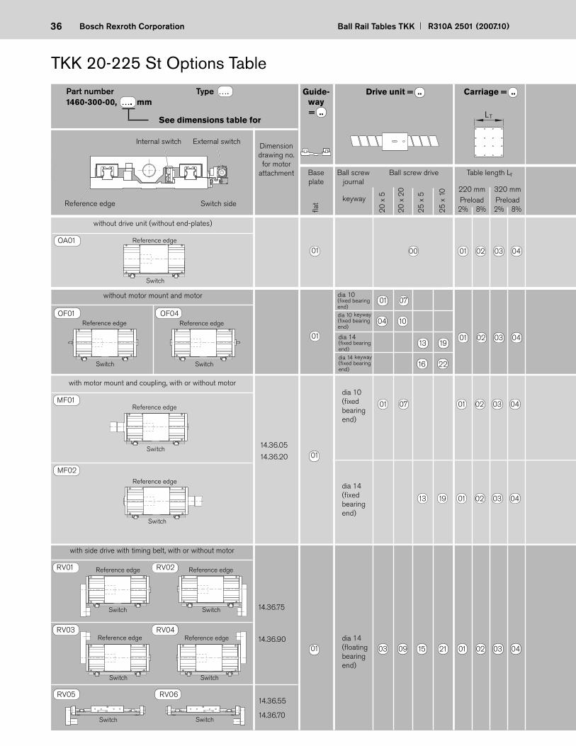
TKK 20-225 St Options Table
See dimensions table for
Dimension drawing no. for motor
attachment Ball screw journal
Ball screw drive
without drive unit (without end-plates)
without motor mount and motor
OA01
OF01 OF04
1460-300-00, …. mmDrive unit = ..
Base plate
Guide-way = ..
Carriage = ..
LT
8%2% 8%2%Preload
Table length LT
320 mm220 mmPreload
01 00 01 02 03 04
Part number Type ….
External switchInternal switch
Switch side
Reference edge
Switch
Reference edge
Switch
Reference edge
Switch
25
x 1
0
25
x 5
20
x 2
0
20
x 5
01 02 03 04
16 22
13 19
04 10
01 07
01
MF01
with motor mount and coupling, with or without motor
MF02
14.36.05
14.36.20
Reference edge
Switch
Reference edge
Switch
dia 10 (fi xed bear ing end)
dia 14 (fi xed bear ing end)
13 19 01 02 03 04
01 07 01 02 03 04
01
RV01 RV02
RV03 RV04
14.36.75
14.36.90
with side drive with timing belt, with or without motor
dia 14 (fl oating bear ing end)
Reference edge
Switch
Reference edge
Switch
Reference edge
Switch
Reference edge
Switch
01
RV05 RV06 14.36.55
14.36.70 Switch Switch
03 09 15 21 01 02 03 04
dia 10 keyway (fi xed bearing end)
dia 14 keyway (fi xed bearing end)
keyway
dia 14 (fi xed bearing end)
dia 10 (fi xed bearing end)
Reference edge
fl at

37R310A 2501 (2007.10) Ball Rail Tables TKK Bosch Rexroth Corporation
Please check whether the selected combination is a permissible one (load capacities, moments, maximum speeds, motor data, etc.)!
Mounting direction as per
diagram
Motor type
Polyurethane bellows
with-out
with with-out
withi =
Internal switch
External switching cam with profi led support
External socket-
plug (loose)
External switch
PNP NO
PNP NC
PNP NO
PNP NC
Mechanical
Cable duct (loose)
Motor attachment = ..
Motor = .. Position measuring system = ..
Documen-tation = ..
00 01 00 01
17
26
15 -A ±….
13 -A ±….
11 -A ±….
OF01-OF04 00 without 00
Mechanical
upon request
Cable duct
TypeLength in mm
07
20 - X....
OA01 00 without 00 00 upon
request
without switch
without cable duct 00
1st switch = ..-. ± ….. mm2nd switch = ..-. ± ….. mm3rd switch = ..-. ± ….. mmCable duct = .. - . .... mm
Socket-plug = ..Switching cam = ..
Cover = ..
Friction moment
02
Lead deviation
03
Sequence accuracy
04
Positioning accuracy
05
05 -I ±…..
01 -I ±…..
03 -I ±…..
Socket-plug on
end-plate
Switch-
– 0 +
L/2
Reference edge
Switch
Direction
1 MF01-MF02
1 MF01-MF02
withoutMMD 082A
withoutMKD 41B
without
MMD 082A
10
0204
06
11
00600010
0060
1
1
2
1.5
RV01-RV04
RV05-RV06
RV01-RV04
RV05-RV06
RV01-RV04
RV05-RV06
RV01-RV04
RV05-RV06
RV01-RV04
RV05-RV06
RV01-RV04
RV05-RV06
without
MHD 71A-061
00
61
without
MKD 41B
00
10
without
MMD 082A 60
00 1
1.5
37
39
40
45
46
48
49
50
51
52
47
38
without
MKD 71B-061
MHD 71B-061
00
11
62
Stan
dard
repo
rt
Spec
ial
repo
rt
Switch typePos. and directionSwitch activation point in mm
Switch typePos. and directionSwitch activation point in mm
Glassscale
38 Ball Rail Tables TKK R310A 2501 (2007.10)Bosch Rexroth Corporation
Typ
ID-N
rD
atumD
eutsche Star G
mbH
97419 Schw
einfurt
h=1.8ø10
h73
P9
27
203
27ø10
h7
30 6020
ø 55
-0.0
3
F 133542
1335
G x 120L
F
ø 55
-0.0
3
19065 54.5
220 (320)
33
96
26
h=3ø14
h75
P9
27
203
27ø14
h7
19.5
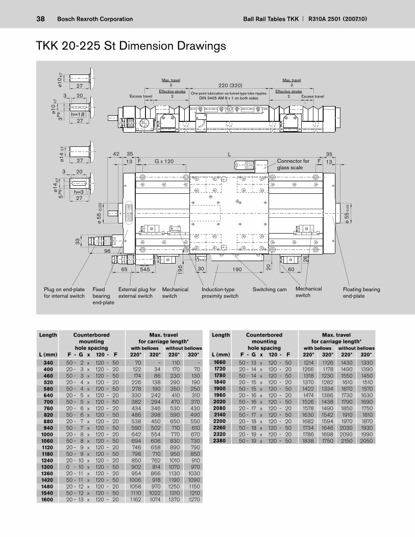
External plug for external switch
Mechanical switch
Switching camInduction-type proximity switch
Effective stroke2
Effective stroke2
Max. travel2
Max. travel2
Excess travel Excess travel
Connector for glass scale
Mechanical switch
Plug on end-plate for internal switch
Floating bearing end-plate
One-point lubrication via funnel-type lube nipples DIN 3405 AM 8 x 1 on both sides
Fixed bearing end-plate
TKK 20-225 St Dimension Drawings
Length Counterbored Max. travel mounting for carriage length* hole spacing with bellows without bellows L (mm) F - G x 120 - F 220* 320* 220* 320*
Length Counterbored Max. travel mounting for carriage length* hole spacing with bellows without bellows L (mm) F - G x 120 - F 220* 320* 220* 320*
50 - 2 x 120 - 50 70 - 110 - 20 - 3 x 120 - 20 122 34 170 70 50 - 3 x 120 - 50 174 86 230 130 20 - 4 x 120 - 20 226 138 290 190 50 - 4 x 120 - 50 278 190 350 250 20 - 5 x 120 - 20 330 242 410 310 50 - 5 x 120 - 50 382 294 470 370 20 - 6 x 120 - 20 434 346 530 430 50 - 6 x 120 - 50 486 398 590 490 20 - 7 x 120 - 20 538 450 650 550 50 - 7 x 120 - 50 590 502 710 610 20 - 8 x 120 - 20 642 554 770 670 50 - 8 x 120 - 50 694 606 830 730 20 - 9 x 120 - 20 746 658 890 790 50 - 9 x 120 - 50 798 710 950 850 20 - 10 x 120 - 20 850 762 1010 910 0 - 10 x 120 - 50 902 814 1070 970 20 - 11 x 120 - 20 954 866 1130 1030 50 - 11 x 120 - 50 1006 918 1190 1090 20 - 12 x 120 - 20 1058 970 1250 1150 50 - 12 x 120 - 50 1110 1022 1310 1210 20 - 13 x 120 - 20 1162 1074 1370 1270
340 400 460 520 580 640 700 760 820 880 940 1000 1060 1120 1180 1240 1300 1360 1420 1480 1540 1600
1660 1720 1780 1840 1900 1960 2020 2080 2140 2200 2260 2320 2380
50 - 13 x 120 - 50 1214 1126 1430 1330 20 - 14 x 120 - 20 1266 1178 1490 1390 50 - 14 x 120 - 50 1318 1230 1550 1450 20 - 15 x 120 - 20 1370 1282 1610 1510 50 - 15 x 120 - 50 1422 1334 1670 1570 20 - 16 x 120 - 20 1474 1386 1730 1630 50 - 16 x 120 - 50 1526 1438 1790 1690 20 - 17 x 120 - 20 1578 1490 1850 1750 50 - 17 x 120 - 50 1630 1542 1910 1810 20 - 18 x 120 - 20 1682 1594 1970 1870 50 - 18 x 120 - 50 1734 1646 2030 1930 20 - 19 x 120 - 20 1786 1698 2090 1990 50 - 19 x 120 - 50 1838 1750 2150 2050
39R310A 2501 (2007.10) Ball Rail Tables TKK Bosch Rexroth Corporation
20 20
160ø9200225
36
H13
223
75
193040
6682153
45
35
50
56
Front view
Reference edge
M8-18 deep in each end-plate 4x
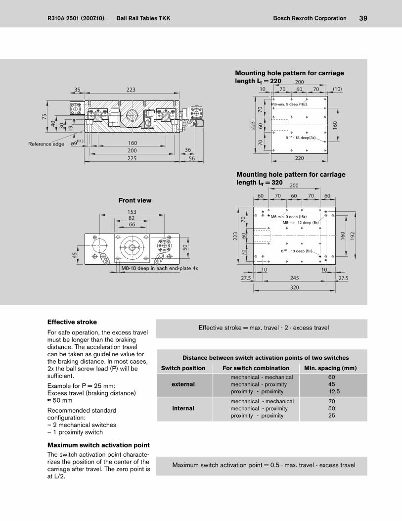
Distance between switch activation points of two switches
Switch position For switch combination Min. spacing (mm)
mechanical - mechanical 60 external mechanical - proximity 45 proximity - proximity 12.5
mechanical - mechanical 70 internal mechanical - proximity 50 proximity - proximity 25
Effective stroke = max. travel - 2 · excess travelEffective stroke
Maximum switch activation point = 0.5 · max. travel - excess travel
Maximum switch activation point
For safe operation, the excess travel must be longer than the braking distance. The acceleration travel can be taken as guideline value for the braking distance. In most cases, 2x the ball screw lead (P) will be suffi cient.
Example for P = 25 mm:Excess travel (braking distance)
50 mm
Recommended standard confi guration:– 2 mechanical switches– 1 proximity switch
The switch activation point characte-rizes the position of the center of the carriage after travel. The zero point is at L/2.
70 60
10
27.5245
223
160
70
607060
27.5
6070
702006070 (10)10
7060
70
10
223
220
160
192
320
200
Mounting hole pattern for carriage length LT = 220
Mounting hole pattern for carriage length LT = 320
M8-min. 12 deep (8x)M6-min. 9 deep (16x)
M6-min. 9 deep (16x)
8 H7 - 18 deep (5x)
8 H7 - 18 deep(3x)
40 Ball Rail Tables TKK R310A 2501 (2007.10)Bosch Rexroth Corporation
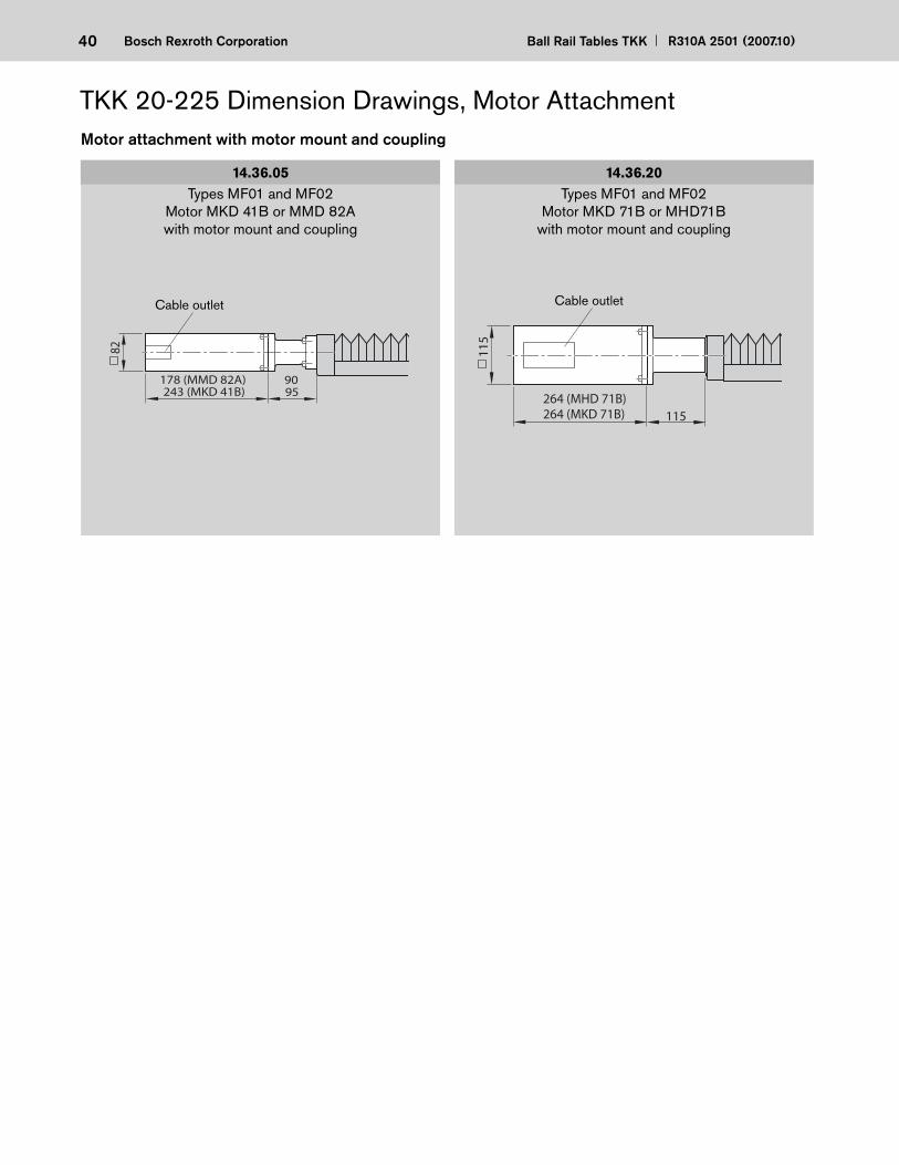
243 (MKD 41B)
82
95178 (MMD 82A) 90
Motor attachment with motor mount and coupling
14.36.05Types MF01 and MF02
Motor MKD 41B or MMD 82A with motor mount and coupling
14.36.20Types MF01 and MF02
Motor MKD 71B or MHD71B with motor mount and coupling
115264 (MHD 71B)264 (MKD 71B)
115
Cable outletCable outlet
TKK 20-225 Dimension Drawings, Motor Attachment
41R310A 2501 (2007.10) Ball Rail Tables TKK Bosch Rexroth Corporation
116
287
155
at i
=1
152
at i
=2
205 66
115
56
88
82
243 (MKD 41B) 51
47.5
122
231
178 (MMD 82A)
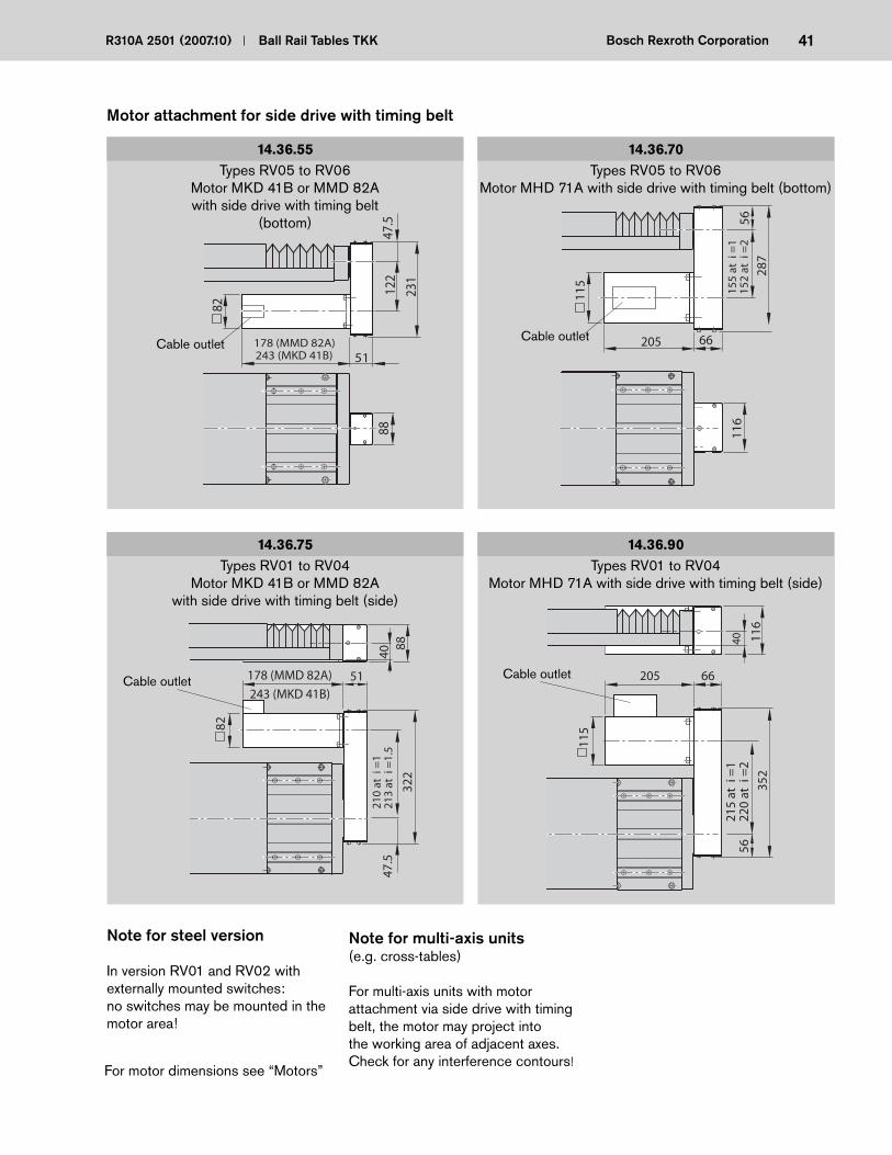
Types RV01 to RV04Motor MKD 41B or MMD 82A
with side drive with timing belt (side)
14.36.75 14.36.90Types RV01 to RV04
Motor MHD 71A with side drive with timing belt (side)
Types RV05 to RV06 Motor MKD 41B or MMD 82Awith side drive with timing belt
(bottom)
14.36.55 14.36.70Types RV05 to RV06
Motor MHD 71A with side drive with timing belt (bottom)
Cable outlet Cable outlet
Cable outletCable outlet
115
215
at i
=1
220
at i
=2
352
5640 11
6
66205
Note for steel version
In version RV01 and RV02 with externally mounted switches:no switches may be mounted in the motor area!
For motor dimensions see “Motors”
Note for multi-axis units (e.g. cross-tables)
For multi-axis units with motor attachment via side drive with timing belt, the motor may project into the working area of adjacent axes. Check for any interference contours!
Motor attachment for side drive with timing belt
82
178 (MMD 82A) 51
210
at i
=1
213
at i
=1.
5
322
47.5
4088
243 (MKD 41B)
42 Ball Rail Tables TKK R310A 2501 (2007.10)Bosch Rexroth Corporation
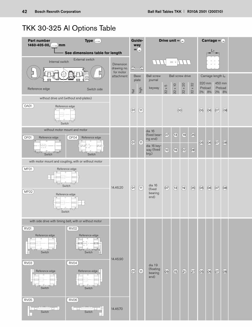
TKK 30-325 Al Options Table
See dimensions table for length
Dimension drawing no. for motor
attachment Ball screw journal
Ball screw drive
32
x 5
32
x 1
0
32
x 2
0
without drive unit (without end-plates)
without motor mount and motor
with motor mount and coupling, with or without motor
14.46.20
with side drive with timing belt, with or without motor
14.46.90
14.46.70
OA01
MF01
MF02
OF01 OF04
RV01 RV02
RV05 RV06
RV03 RV04
1460-405-00, …. mmDrive unit = ..
Reference edge Switch side
External switchInternal switch
32
x 3
2
10 16 22 28
dia 16 (fi xed bea ring end)
dia 19 (fl oating bea ring end)
fl at
high
Guide-way = ..
Carriage = ..
8%2% 8%2%Preload
Carriage length LT
450 mm320 mmPreload
LT
07 13 19 25
01 11 05 06 07 08
01 11 07 13 19 25 05 06 07 08
01 11 09 15 21 27 05 06 07 08
Reference edge
Switch
Reference edge
Switch
Reference edge
Switch
Reference edge
Switch
Reference edge
Switch
Reference edge
Switch
Reference edge
Switch
Reference edge
Switch
Reference edge
Switch
Switch Switch
keyway
Base plate
Part number Type ….
01 11 00 05 06 07 08
dia 16 (fi xed bea r -ing end)
dia 16 key-way (fi xed brg.)
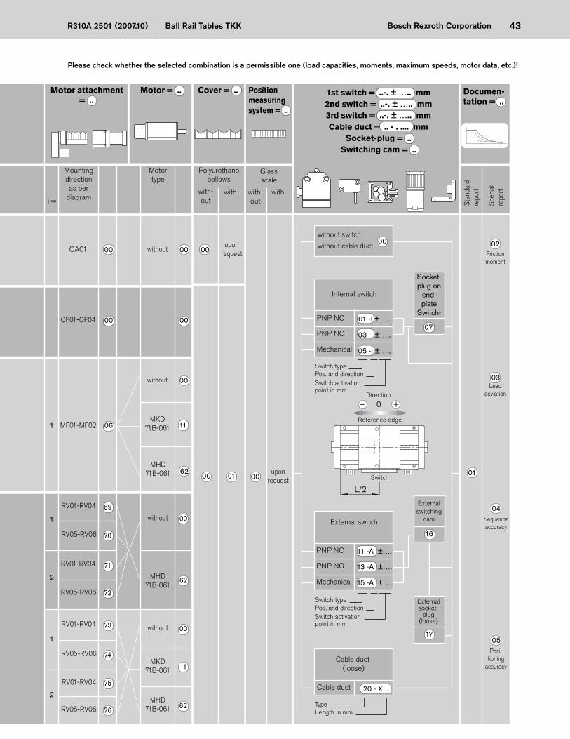
43R310A 2501 (2007.10) Ball Rail Tables TKK Bosch Rexroth Corporation
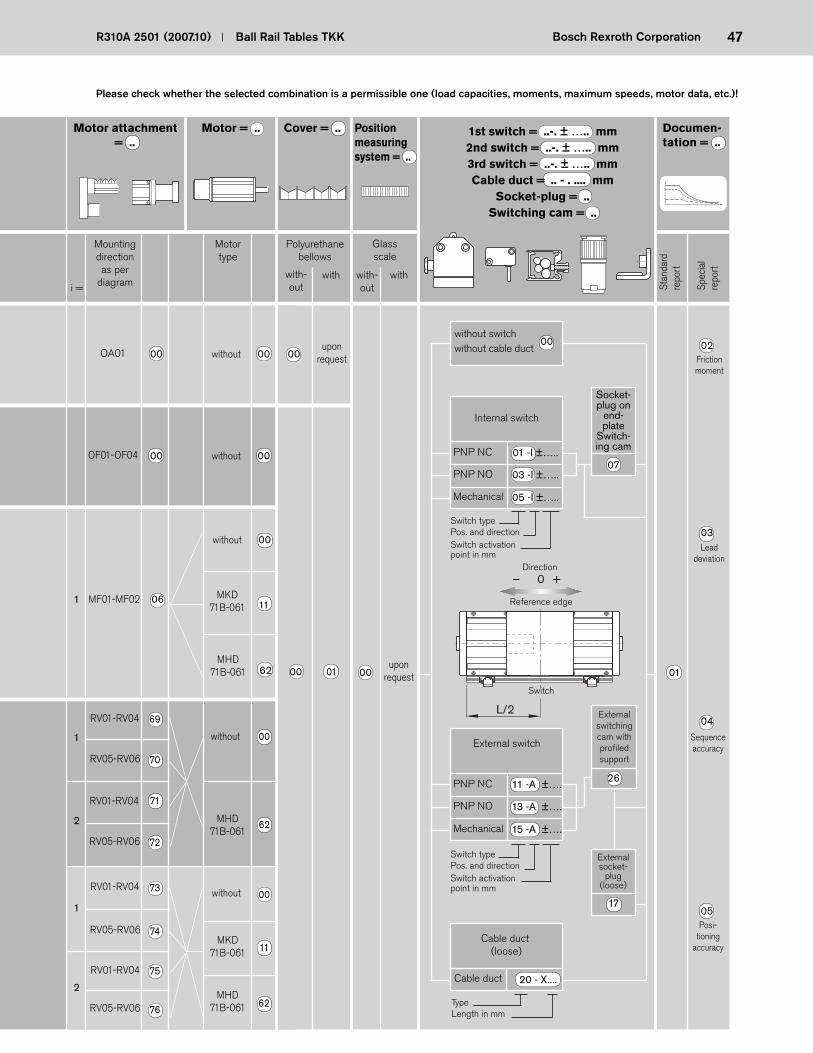
Mounting direction as per
diagram
Motor type
Polyurethane bellows
with -out
with with-out
withi =
1 MF01-MF02
1
2
Motor attachment = ..
Motor = .. Position measuring system = ..
Documen-tation = ..
OF01-OF04 00 00
06
17
16
15 -A ±….
13 -A ±….
11 -A ±….
RV01-RV04
2
1
upon request
07
20 - X....
OA01 00 without 00 00 upon
request
00
1st switch = ..-. ± ….. mm2nd switch = ..-. ± ….. mm3rd switch = ..-. ± ….. mmCable duct = .. - . .... mm
Socket-plug = ..Switching cam = ..
01 -I ±…..
05 -I ±…..
Cover = ..
without 00
62
Please check whether the selected combination is a permissible one (load capacities, moments, maximum speeds, motor data, etc.)!
L/2
– 0 +
Reference edge
Switch
Direction
Friction moment
02
Lead deviation
03
Sequence accuracy
04
Posi -tioning
accuracy
05
00 01 00
03 -I ±…..
MKD71B-061
MHD71B-061
RV05-RV06
RV01-RV04
RV05-RV06
RV01-RV04
RV05-RV06
RV01-RV04
RV05-RV06
69
70
71
72
73
74
75
76
without 00
without
MKD71B-061
MHD71B-061
MHD71B-061
62
00
11
62
11
Stan
dard
repo
rt
Spec
ial
repo
rt
without switch
without cable duct
Internal switch
PNP NO
PNP NC
Mechanical
Socket-plug on
end-plate
Switch-
Switch typePos. and directionSwitch activation point in mm
01
External switching
cam
External socket-
plug (loose)
External switch
PNP NO
PNP NC
Mechanical
Switch typePos. and directionSwitch activation point in mm
Cable duct (loose)
Cable duct
TypeLength in mm
Glassscale

44 Ball Rail Tables TKK R310A 2501 (2007.10)Bosch Rexroth Corporation
Length Counterbored Max. travel mounting for carriage length* hole spacing with bellows without bellows L (mm) F - G x 120 - F 320* 450* 320* 450*
Length Counterbored Max. travel mounting for carriage length* hole spacing with bellows without bellows L (mm) F - G x 120 - F 320* 450* 320* 450*
Typ
ID-N
rD
atumD
eutsche Star G
mbH
97419 Schw
einfurt
30 60
ø68
-0.0
3
F 143558
1435
G x 160L
F
ø68 -
0.03
19065 54.5
33
96
19.5
26
320 (450)
42
ø16
h7
h=3
ø16 h
7
5 42
284
P9
20
One-point lubrication via funnel-type lube nipples DIN 3405 AM 8 x 1 on both sides
Switching cam
TKK 30-325 Al Dimension Drawings
Max. travel2
Max. travel2
Effective stroke2
Effective stroke2 Excess travelExcess travel
Connector for glass scale
Plug on end-plate for internal switch
Induction-type proximity switch
External plug for external switch
Mechanical switch
Floating bearing end-plate
Mechanical switch
70 - 2 x 160 - 70 - - 130 - 30 - 3 x 160 - 30 154 - 210 - 70 - 3 x 160 - 70 225 109 290 160 30 - 4 x 160 - 30 297 180 370 240 70 - 4 x 160 - 70 368 251 450 320 30 - 5 x 160 - 30 439 322 530 400 70 - 5 x 160 - 70 510 394 610 480 30 - 6 x 160 - 30 582 465 690 560 70 - 6 x 160 - 70 653 536 770 640 30 - 7 x 160 - 30 724 604 850 720 70 - 7 x 160 - 70 795 679 930 800 30 - 8 x 160 - 30 866 750 1010 880 70 - 8 x 160 - 70 938 821 1090 960 30 - 9 x 160 - 30 1009 892 1170 1040 70 - 9 x 160 - 70 1080 963 1250 1120 30 - 10 x 160 - 30 1151 1035 1330 1200
Fixed bearing end-plate
70 - 10 x 160 - 70 1223 1106 1410 1280 30 - 11 x 160 - 30 1294 1177 1490 1360 70 - 11 x 160 - 70 1365 1248 1570 1440 30 - 12 x 160 - 30 1436 1320 1650 1520 70 - 12 x 160 - 70 1507 1391 1730 1600 30 - 13 x 160 - 30 1579 1462 1810 1680 70 - 13 x 160 - 70 1650 1533 1890 1760 30 - 14 x 160 - 30 1721 1605 1970 1840 70 - 14 x 160 - 70 1792 1676 2050 1920 30 - 15 x 160 - 30 1864 1747 2130 2000 70 - 15 x 160 - 70 1935 1818 2210 2080 30 - 16 x 160 - 30 2006 1889 2290 2160 70 - 16 x 160 - 70 2077 1961 2370 2240 30 - 17 x 160 - 30 2148 2032 2450 2320 70 - 17 x 160 - 70 2220 2103 2530 2400
460 540 620 700 780 860 940 1020 1100 1180 1260 1340 1420 1500 1580 1660
1740 1820 1900 1980 2060 2140 2220 2300 2380 2460 2540 2620 2700 2780 2860
45R310A 2501 (2007.10) Ball Rail Tables TKK Bosch Rexroth Corporation
3030
3030
W230ø11
300325 33
Slot ?0.9H13
90
153050
32335
120
6080
45
W
90111210
52
46
13.5
18
+0.
38
+0.
5
9 +0.3
+0.5
R11 1)
Front view
Reference edge
M8- 20 deep in each end-plate 4x
90 90
450350
230
103
10
77
909090
9090
7790
40 1040
103
26.5
9090
9026
.5
323
(25)90909025320
244
290 (15)15
190
41020 (20)
270
323
190
29080 80
Mounting hole pattern for carriage length LT = 320
Mounting hole pattern for carriage length LT = 450
M8-min. 12 deep(16x)
M8-min. 12 deep (32x)
Distance between switch activation points of two switches
Switch position For switch combination Min. spacing (mm)
mechanical - mechanical 60 external mechanical - proximity 45 proximity - proximity 12.5
mechanical - mechanical 70 internal mechanical - proximity 50 proximity - proximity 25
Detail W
Effective stroke = max. travel - 2 · excess travelEffective stroke
Maximum switch activation point
For safe operation, the excess travel must be longer than the braking distance. The acceleration travel can be taken as guide line value for the braking distance. In most cases, 2x the ball screw lead (P) will be suffi cient.
Example for P = 32 mm:Excess travel (braking distance)
64 mm
Recommended standard confi guration:– 2 mechanical switches– 1 proximity switch
The switch activation point charac-terizes the position of the center of the carriage after travel. The zero point is at L/2.
High base plate, screwed and fastened together by pins
Flat base plate
Maximum switch activation point = 0.5 · max. travel - excess travel
10 H7 - 20 deep (3x)
10 H7 - 20 deep (5x)
Reference edge
1) 27 deep (4x)

46 Ball Rail Tables TKK R310A 2501 (2007.10)Bosch Rexroth Corporation
TKK 30-325 St Options Table
See dimensions table for length
Dimension drawing no. for motor at-
tachment Ball screw journal
Ball screw drive
32
x 5
32
x 1
0
32
x 2
0
with motor mount and coupling, with or without motor
14.46.20
with side drive with timing belt, with or without motor
14.46.90
14.46.70
OA01
MF01
MF02
OF01 OF04
RV01 RV02
RV05 RV06
RV03 RV04
1460-400-00, …. mmDrive unit = ..
32
x 3
2
dia 16 (fi xed bea r -ing end)
10 16 22 28
dia 16 (fi xed bea ring end)
dia 19 (fl oating bea ring end)
Base plate
fl at
Guide-way = ..
Part number Type …. Carriage = ..
8%2% 8%2%Preload
Carriage length LT
450 mm320 mmPreload
LT
01 00 05 06 07 08
07 13 19 25
01 09 15 21 27 05 06 07 08
Reference edge
Switch
Reference edge
Switch
Reference edge
Switch
Reference edge
Switch
Switch
Reference edge
Switch Switch
Reference edge
Switch
Reference edge
Switch
Reference edge
Switch
Reference edge
Switch
01 05 06 07 08
01 07 13 19 25 05 06 07 08
dia 16 key-way (fi xed brg.)
keyway
without drive unit (without end-plates)
without motor mount and motor
Reference edge Switch side
External switchInternal switch
47R310A 2501 (2007.10) Ball Rail Tables TKK Bosch Rexroth Corporation
Motor attachment = ..
Motor = .. Position measuring system = ..
Documen-tation = ..
OF01-OF04 00 without 00
00 01 00 01
17
26
15 -A ±….
13 -A ±….
11 -A ±….
upon request
07
20 - X....
OA01 00 without 00 00 upon
request
00
1st switch = ..-. ± ….. mm2nd switch = ..-. ± ….. mm3rd switch = ..-. ± ….. mmCable duct = .. - . .... mm
Socket-plug = ..Switching cam = ..
01 -I ±…..
03 -I ±…..
05 -I ±…..
Cover = ..
02
03
04
05
Please check whether the selected combination is a permissible one (load capacities, moments, maximum speeds, motor data, etc.)!
– 0 +
L/2
1 MF01-MF02
1
2
06
RV01-RV04
2
1
RV05-RV06
RV01-RV04
RV05-RV06
RV01-RV04
RV05-RV06
RV01-RV04
RV05-RV06
69
70
71
72
73
74
75
76
without 00
MHD71B-061
62
without
MKD71B-061
MHD71B-061
00
11
62
without 00
11
62
MKD71B-061
MHD71B-061
Mounting direction as per
diagram
Motor type
Polyurethane bellows
with -out
with with-out
withi =
without switchwithout cable duct
Stan
dard
repo
rt
Spec
ial
repo
rt
Internal switch
PNP NO
PNP NC
Mechanical
Socket-plug on
end-plate
Switch-ing cam
Switch typePos. and directionSwitch activation point in mm
Friction moment
Lead deviation
Sequence accuracy
Posi -tioning
accuracy
Reference edge
Switch
Direction
External switching cam with profi led support
External switch
PNP NO
PNP NC
Mechanical
Switch typePos. and directionSwitch activation point in mm
External socket-
plug (loose)
Cable duct (loose)
Cable duct
TypeLength in mm
Glassscale
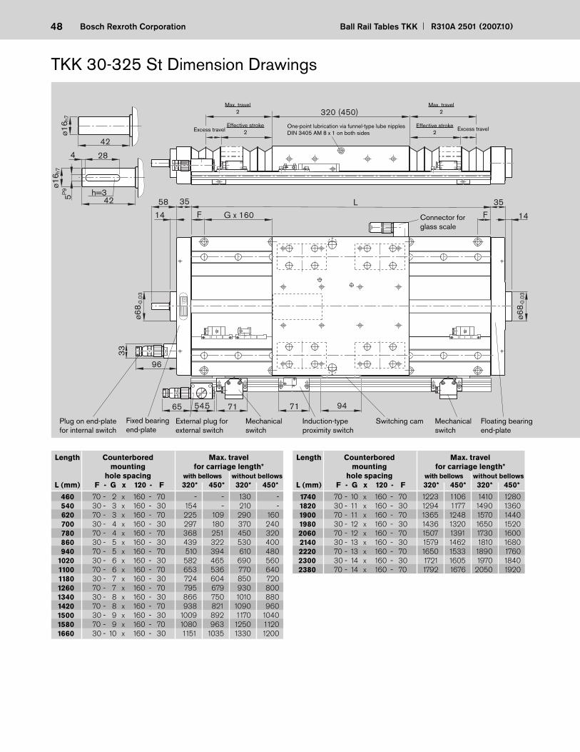
48 Ball Rail Tables TKK R310A 2501 (2007.10)Bosch Rexroth Corporation
Typ
ID-N
rD
atumD
eutsche Star G
mbH
97419 Schw
einfurt
ø68 -
0.03
F 14
3558
14
35
G x 160L
F
ø68 -
0.03
65 54.5
33
96
h=3
ø16 h
7
5P9
42
284
320 (450)
42
ø16 h
7
71 71 94
TKK 30-325 St Dimension Drawings
Connector for glass scale
External plug for external switch
Mechanical switch
Induction-type proximity switch
Switching cam Mechanical switch
Max. travel2
Excess travelEffective stroke
2One-point lubrication via funnel-type lube nipples DIN 3405 AM 8 x 1 on both sides
Max. travel2
Effective stroke2
Excess travel
Floating bearing end-plate
Plug on end-plate for internal switch
Fixed bearing end-plate
Length Counterbored Max. travel mounting for carriage length* hole spacing with bellows without bellows L (mm) F - G x 120 - F 320* 450* 320* 450*
Length Counterbored Max. travel mounting for carriage length* hole spacing with bellows without bellows L (mm) F - G x 120 - F 320* 450* 320* 450*
70 - 2 x 160 - 70 - - 130 - 30 - 3 x 160 - 30 154 - 210 - 70 - 3 x 160 - 70 225 109 290 160 30 - 4 x 160 - 30 297 180 370 240 70 - 4 x 160 - 70 368 251 450 320 30 - 5 x 160 - 30 439 322 530 400 70 - 5 x 160 - 70 510 394 610 480 30 - 6 x 160 - 30 582 465 690 560 70 - 6 x 160 - 70 653 536 770 640 30 - 7 x 160 - 30 724 604 850 720 70 - 7 x 160 - 70 795 679 930 800 30 - 8 x 160 - 30 866 750 1010 880 70 - 8 x 160 - 70 938 821 1090 960 30 - 9 x 160 - 30 1009 892 1170 1040 70 - 9 x 160 - 70 1080 963 1250 1120 30 - 10 x 160 - 30 1151 1035 1330 1200
70 - 10 x 160 - 70 1223 1106 1410 1280 30 - 11 x 160 - 30 1294 1177 1490 1360 70 - 11 x 160 - 70 1365 1248 1570 1440 30 - 12 x 160 - 30 1436 1320 1650 1520 70 - 12 x 160 - 70 1507 1391 1730 1600 30 - 13 x 160 - 30 1579 1462 1810 1680 70 - 13 x 160 - 70 1650 1533 1890 1760 30 - 14 x 160 - 30 1721 1605 1970 1840 70 - 14 x 160 - 70 1792 1676 2050 1920
460 540 620 700 780 860 940 1020 1100 1180 1260 1340 1420 1500 1580 1660
1740 1820 1900 1980 2060 2140 2220 2300 2380
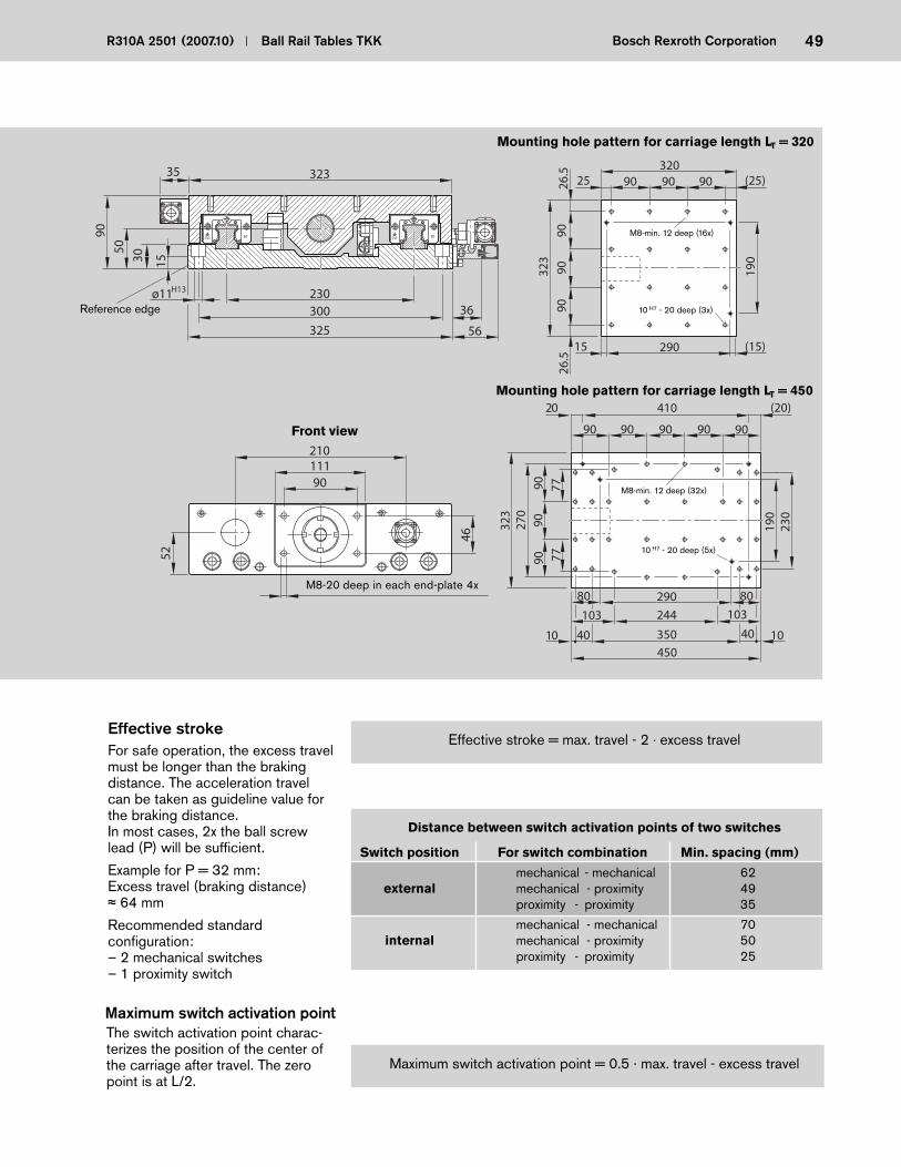
49R310A 2501 (2007.10) Ball Rail Tables TKK Bosch Rexroth Corporation
3030
230ø11300
325
36
H13
90
153050
32335
90111210
52
46
56
Reference edge
Front view
Distance between switch activation points of two switches
Switch position For switch combination Min. spacing (mm)
mechanical - mechanical 62 external mechanical - proximity 49 proximity - proximity 35
mechanical - mechanical 70 internal mechanical - proximity 50 proximity - proximity 25
Effective stroke = max. travel - 2 · excess travelEffective stroke
Maximum switch activation point = 0.5 · max. travel - excess travel
Maximum switch activation point
For safe operation, the excess travel must be longer than the braking distance. The acceleration travel can be taken as guide line value for the braking distance. In most cases, 2x the ball screw lead (P) will be suffi cient.
Example for P = 32 mm:Excess travel (braking distance)
64 mm
Recommended standard confi guration:– 2 mechanical switches– 1 proximity switch
The switch activation point charac-terizes the position of the center of the carriage after travel. The zero point is at L/2.
90 90
450350
230
103
10
77
909090
9090
7790
40 1040
103
26.5
9090
9026
.5
323
(25)90909025320
244
290 (15)15
190
41020 (20)
270
323
190
29080 80
Mounting hole pattern for carriage length LT = 320
Mounting hole pattern for carriage length LT = 450
M8-min. 12 deep (16x)
M8-min. 12 deep (32x)
10 H7 - 20 deep (3x)
10 H7 - 20 deep (5x)
M8-20 deep in each end-plate 4x
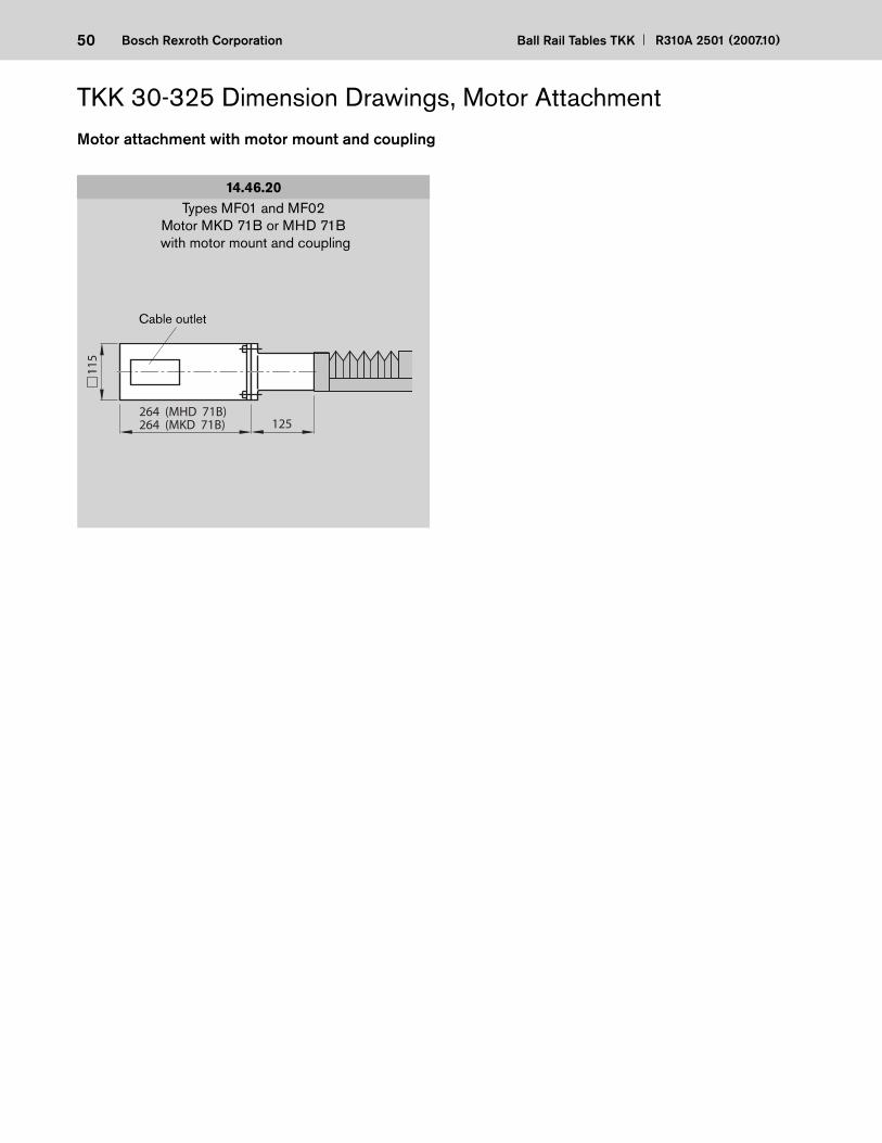
50 Ball Rail Tables TKK R310A 2501 (2007.10)Bosch Rexroth Corporation
264 (MHD 71B)264 (MKD 71B) 125
115
14.46.20Types MF01 and MF02
Motor MKD 71B or MHD 71B with motor mount and coupling
TKK 30-325 Dimension Drawings, Motor Attachment
Cable outlet
Motor attachment with motor mount and coupling

51R310A 2501 (2007.10) Ball Rail Tables TKK Bosch Rexroth Corporation
115
66
265
at i
=2
266
at i
=1
403
59
205 (MHD 71A)264 (MHD 71B)264 (MKD 71B)
50
116
116
115
66
162
at i
= 2
165
at i
= 1
300
56
205 (MHD 71A)264 (MHD 71B)264 (MKD 71B)
Types RV05 to RV06Motor MKD 71B, MHD 71A or MHD 71Bwith side drive with timing belt (bottom)
14.46.70 14.46.90Types RV01 to RV04
Motor MKD 71B, MHD 71A or MHD 71Bwith side drive with timing belt (side)
Cable outlet
Note for steel version
In version RV01 and RV02 with externally mounted switches:no switches may be mounted in the motor area!
Cable outlet
For motor dimensions see “Motors”
Note for multi-axis units (e.g. cross-tables)
For multi-axis units with motor attachment via side drive with timing belt, the motor may project into the working area of adjacent axes. Check for any interference contours!
Motor attachment for side drive with timing belt
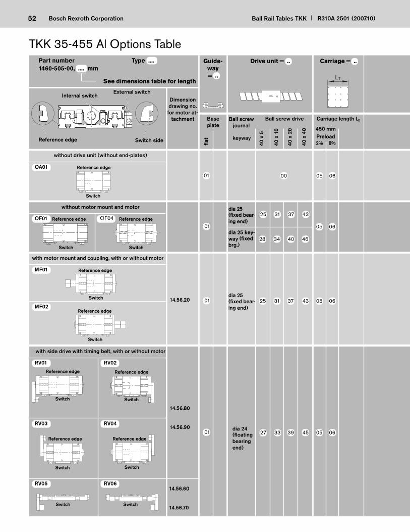
52 Ball Rail Tables TKK R310A 2501 (2007.10)Bosch Rexroth Corporation
TKK 35-455 Al Options Table
See dimensions table for length
40 x
5
40 x
10
40 x
20
14.56.80
14.56.90
14.56.60
14.56.70
OA01
MF01
MF02
OF01 OF04
RV01 RV02
RV05 RV06
RV03 RV04
1460-505-00, .... mmDrive unit = ..
40 x
40
25 31 37 43
dia 25 (fi xed bea r - ing end)
dia 24 (fl oating bea ring end)
14.56.20
Part number Type .... Guide-way = ..
Carriage = ..
8%2%
450 mmPreload
LT
28 34 40 46
01 05 06
01 25 31 37 43 05 06
01 27 33 39 45 05 06
Reference edge
Switch
Reference edge
Switch
Reference edge
Switch
Reference edge
Switch
Reference edge
Switch
Reference edge
Switch
Reference edge
Switch
Reference edge
Switch
Reference edge
Switch
Switch Switch
dia 25 key-way (fi xed brg.)
01 00 05 06
Dimension drawing no. for motor at-
tachment
without drive unit (without end-plates)
Reference edge Switch side
External switchInternal switch
Ball screw journal
Ball screw drive
fl at
Carriage length LT
keyway
Base plate
without motor mount and motor
with motor mount and coupling, with or without motor
with side drive with timing belt, with or without motor
dia 25 (fi xed bea r - ing end)
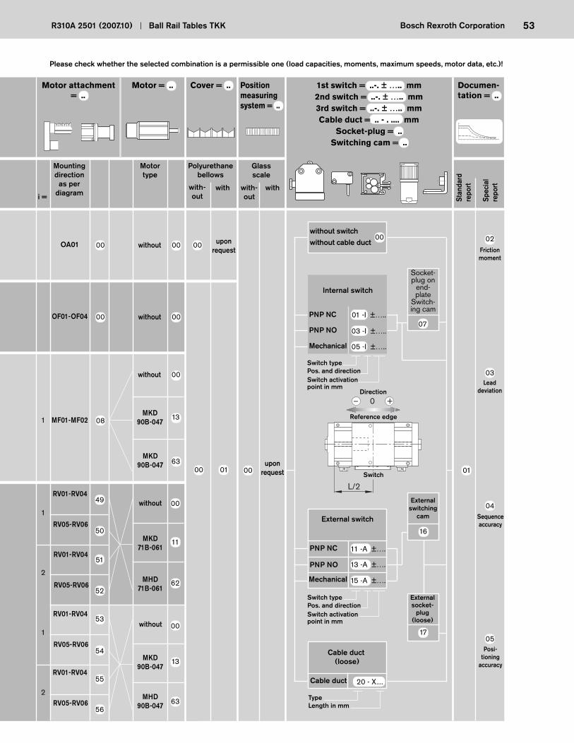
53R310A 2501 (2007.10) Ball Rail Tables TKK Bosch Rexroth Corporation
1
2
Motor attachment = ..
Motor = .. Position measuring system = ..
Documen-tation = ..
OF01-OF04 00 without 00
17
16
15 -A ±….
13 -A ±….
11 -A ±….
RV01-RV04
2
1
upon request
07
20 - X....
OA01 00 without 00 00 upon request
1st switch = ..-. ± ….. mm2nd switch = ..-. ± ….. mm3rd switch = ..-. ± ….. mmCable duct = .. - . .... mm
Socket-plug = ..Switching cam = ..
03 -I ±…..
01 -I ±…..
05 -I ±…..
Cover = ..
L/2
– 0 +
1 MF01-MF02 08 MKD
90B-047
without 00
13
Please check whether the selected combination is a permissible one (load capacities, moments, maximum speeds, motor data, etc.)!
02
03
04
05
00 01 00 01
00
MKD90B-047 63
49
50
51
52
53
54
55
56
00
11
62
00
13
63
RV05-RV06
RV01-RV04
RV05-RV06
RV01-RV04
RV05-RV06
RV01-RV04
RV05-RV06
without
MKD71B-061
MHD71B-061
without
MKD90B-047
MHD90B-047
Mounting direction
as per diagram
Motor type
Polyurethane bellows
with -out
with with-out
withi = St
anda
rdre
port
Spec
ial
repo
rt
without switch
without cable duct
Internal switch
PNP NO
PNP NC
Mechanical
Socket-plug on
end-plate
Switch-ing cam
Switch typePos. and directionSwitch activation point in mm
Friction moment
Lead deviation
Sequence accuracy
Posi -tioning
accuracy
Reference edge
Switch
Direction
External switching
camExternal switch
PNP NO
PNP NC
Switch typePos. and directionSwitch activation point in mm
Mechanical
External socket-
plug (loose)
Cable duct (loose)
Cable duct
TypeLength in mm
Glassscale
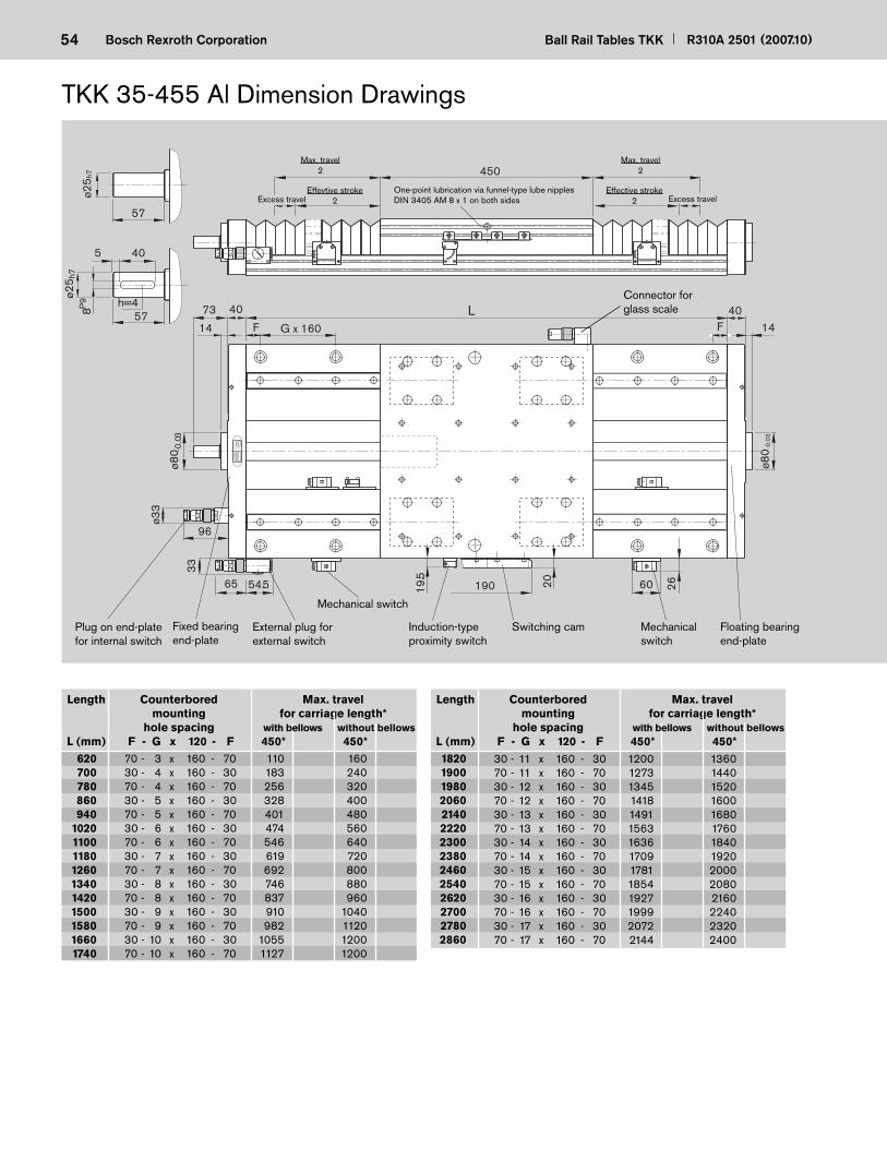
54 Ball Rail Tables TKK R310A 2501 (2007.10)Bosch Rexroth Corporation
Length Counterbored Max. travel mounting for carriage length* hole spacing with bellows without bellows L (mm) F - G x 120 - F 450* 450*
Length Counterbored Max. travel mounting for carriage length* hole spacing with bellows without bellows L (mm) F - G x 120 - F 450* 450*
Typ
ID-N
rD
atumD
eutsche Star G
mbH
97419 Schw
einfurt
F 144073
14
40
G x 160L
F
60
ø80
-0.0
3
ø80 -
0.03
19065 54.5
96
19.5
26
450ø3
3
33
20
h=4
ø25 h
7
8P9
57
405
57
ø25 h
7
TKK 35-455 Al Dimension Drawings
Max. travel2
Effevtive stroke2
One-point lubrication via funnel-type lube nipples DIN 3405 AM 8 x 1 on both sides
Max. travel2
Effective stroke2
Mechanical switch
Induction-type proximity switch
Switching cam Mechanical switch
Connector for glass scale
Excess travel
Floating bearing end-plate
70 - 3 x 160 - 70 110 160 30 - 4 x 160 - 30 183 240 70 - 4 x 160 - 70 256 320 30 - 5 x 160 - 30 328 400 70 - 5 x 160 - 70 401 480 30 - 6 x 160 - 30 474 560 70 - 6 x 160 - 70 546 640 30 - 7 x 160 - 30 619 720 70 - 7 x 160 - 70 692 800 30 - 8 x 160 - 30 746 880 70 - 8 x 160 - 70 837 960 30 - 9 x 160 - 30 910 1040 70 - 9 x 160 - 70 982 1120 30 - 10 x 160 - 30 1055 1200 70 - 10 x 160 - 70 1127 1200
30 - 11 x 160 - 30 1200 1360 70 - 11 x 160 - 70 1273 1440 30 - 12 x 160 - 30 1345 1520 70 - 12 x 160 - 70 1418 1600 30 - 13 x 160 - 30 1491 1680 70 - 13 x 160 - 70 1563 1760 30 - 14 x 160 - 30 1636 1840 70 - 14 x 160 - 70 1709 1920 30 - 15 x 160 - 30 1781 2000 70 - 15 x 160 - 70 1854 2080 30 - 16 x 160 - 30 1927 2160 70 - 16 x 160 - 70 1999 2240 30 - 17 x 160 - 30 2072 2320 70 - 17 x 160 - 70 2144 2400
620 700 780 860 940 1020 1100 1180 1260 1340 1420 1500 1580 1660 1740
1820 1900 1980 2060 2140 2220 2300 2380 2460 2540 2620 2700 2780 2860
Excess travel
External plug for external switch
Plug on end-plate for internal switch
Fixed bearing end-plate
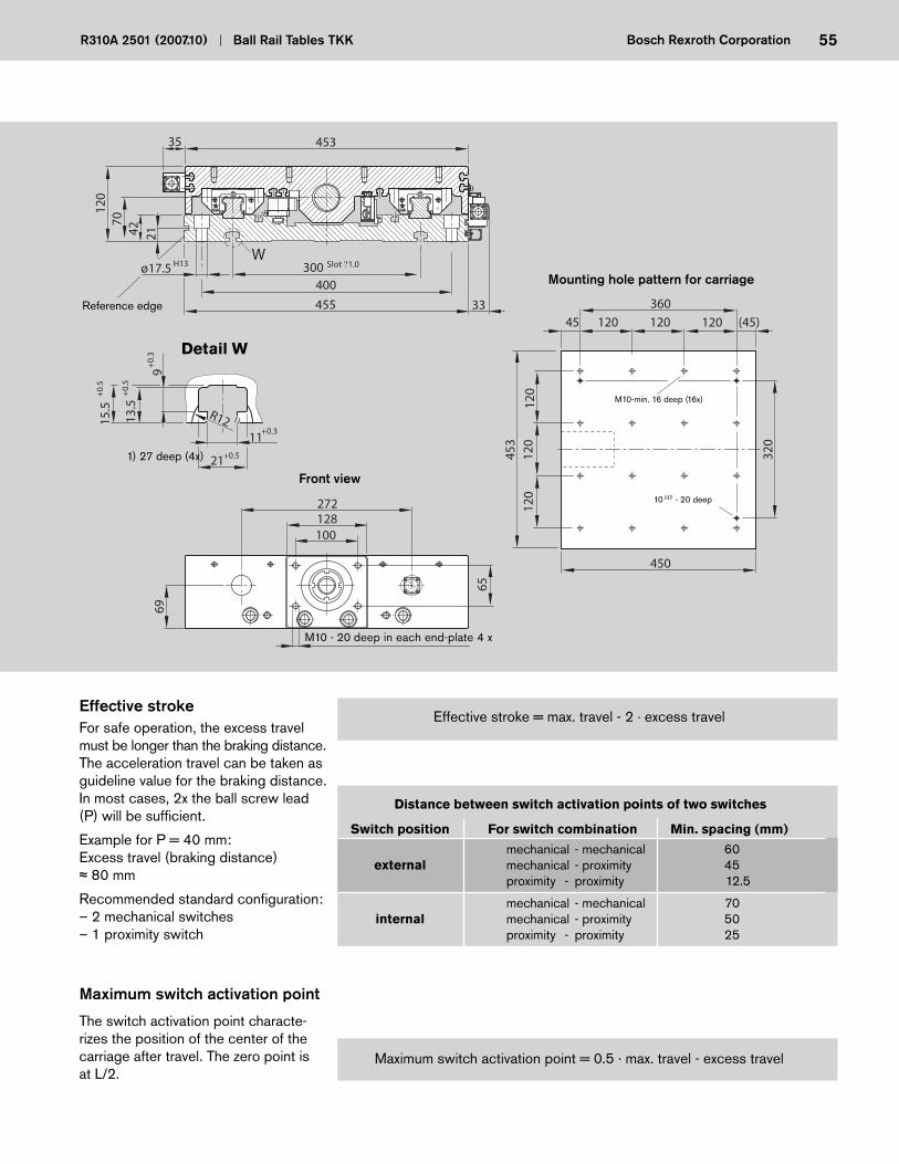
55R310A 2501 (2007.10) Ball Rail Tables TKK Bosch Rexroth Corporation
W
35 35
300ø17.5400
455 33
Slot ?1.0H13
45335
120
214270
13.5
21
+0.
39
+0.
5
11+0.3
+0.5
15.5
+0.
5
100128272
69
65
1)R12
Reference edge
M10 - 20 deep in each end-plate 4 x
Mounting hole pattern for carriage
(45)360
320
120
120 120 12045
120
120
450
453
Detail W
Front view
M10-min. 16 deep (16x)
Distance between switch activation points of two switches
Switch position For switch combination Min. spacing (mm)
mechanical - mechanical 60 external mechanical - proximity 45 proximity - proximity 12.5
mechanical - mechanical 70 internal mechanical - proximity 50 proximity - proximity 25
Effective stroke = max. travel - 2 · excess travelEffective stroke
Maximum switch activation point = 0.5 · max. travel - excess travel
Maximum switch activation point
For safe operation, the excess travel must be longer than the braking distance. The acceleration travel can be taken as guide line value for the braking distance. In most cases, 2x the ball screw lead (P) will be suffi cient.
Example for P = 40 mm:Excess travel (braking distance)
80 mm
Recommended standard confi guration:– 2 mechanical switches– 1 proximity switch
The switch activation point characte-rizes the position of the center of the carriage after travel. The zero point is at L/2.
10 H7 - 20 deep
1) 27 deep (4x)
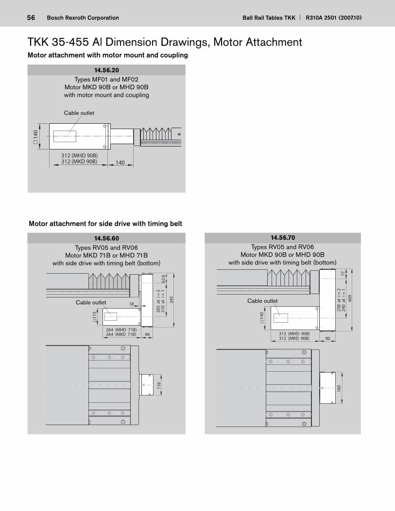
56 Ball Rail Tables TKK R310A 2501 (2007.10)Bosch Rexroth Corporation
116
115
66
205
at
i = 2
210
at
i = 1
345
62.6
264 (MHD 71B)264 (MKD 71B)
18
160
9023
8 a
t i =
224
0 a
t i =
140
9
77
312 (MHD 90B)312 (MKD 90B)
140
TKK 35-455 Al Dimension Drawings, Motor Attachment
14.56.20
14.56.60Types RV05 and RV06
Motor MKD 90B or MHD 90Bwith side drive with timing belt (bottom)
Types RV05 and RV06Motor MKD 71B or MHD 71B
with side drive with timing belt (bottom)
Types MF01 and MF02Motor MKD 90B or MHD 90Bwith motor mount and coupling
Motor attachment for side drive with timing belt
140312 (MHD 90B)312 (MKD 90B)
140
Cable outlet
Motor attachment with motor mount and coupling
Cable outletCable outlet
14.56.70
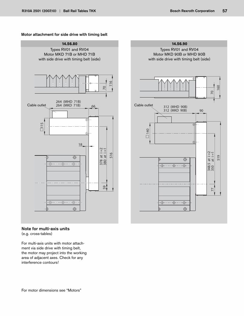
57R310A 2501 (2007.10) Ball Rail Tables TKK Bosch Rexroth Corporation
140
90
348.
5 a
t i =
235
0
at
i =1
519
77
312 (MHD 90B)312 (MKD 90B)
70
160
115
6637
8 a
t i =
238
0 a
t i =
1
516
59264 (MHD 71B)264 (MKD 71B)
70
116
18
14.56.80 14.56.90Types RV01 and RV04
Motor MKD 90B or MHD 90Bwith side drive with timing belt (side)
Types RV01 and RV04Motor MKD 71B or MHD 71B
with side drive with timing belt (side)
Cable outlet Cable outlet
For motor dimensions see “Motors”
Note for multi-axis units (e.g. cross-tables)
For multi-axis units with motor attach-ment via side drive with timing belt, the motor may project into the working area of adjacent axes. Check for any interference contours!
Motor attachment for side drive with timing belt
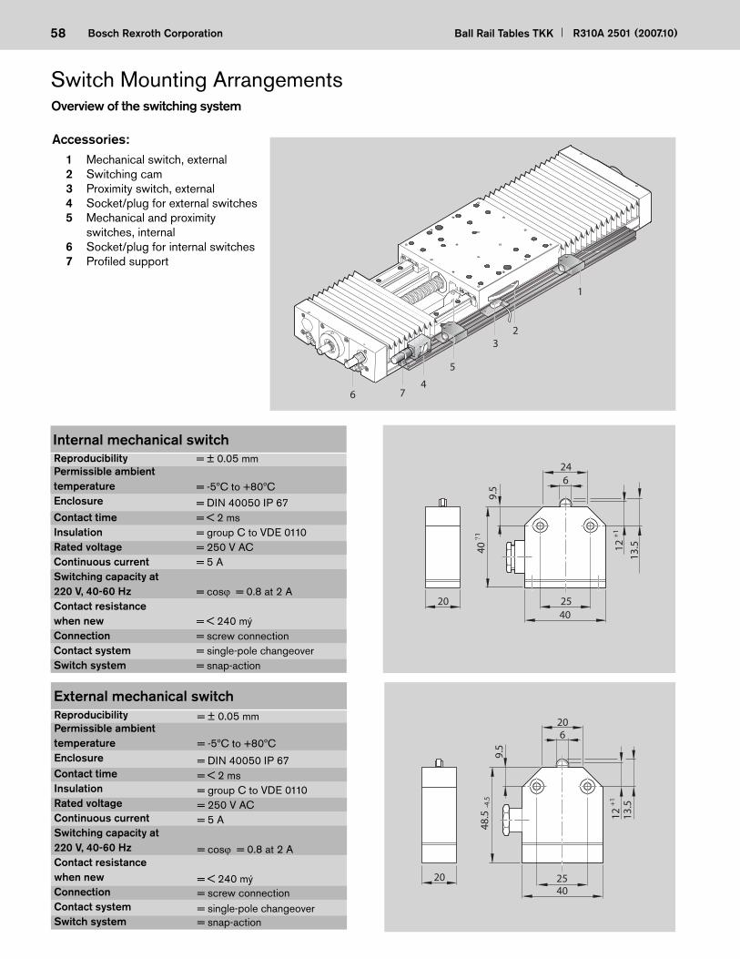
58 Ball Rail Tables TKK R310A 2501 (2007.10)Bosch Rexroth Corporation
Switch Mounting Arrangements
Mechanischer Schalter innen
12+
1
624
4025
40?1
20
9.5
13.5
Overview of the switching system
ReproducibilityPermissible ambienttemperatureEnclosure
Contact timeInsulationRated voltageContinuous currentSwitching capacity at220 V, 40-60 HzContact resistance when newConnectionContact systemSwitch system
= ± 0.05 mm
= -5ºC to +80ºC= DIN 40050 IP 67= < 2 ms= group C to VDE 0110= 250 V AC= 5 A
= cos = 0.8 at 2 A
= < 240 mý= screw connection= single-pole changeover= snap-action
Internal mechanical switch
5
64
1
32
7
Accessories: 1 Mechanical switch, external 2 Switching cam 3 Proximity switch, external 4 Socket/plug for external switches 5 Mechanical and proximity
switches, internal 6 Socket/plug for internal switches 7 Profi led support
ReproducibilityPermissible ambienttemperatureEnclosureContact timeInsulationRated voltageContinuous currentSwitching capacity at220 V, 40-60 HzContact resistance when newConnectionContact systemSwitch system
External mechanical switch= ± 0.05 mm
= -5ºC to +80ºC
= DIN 40050 IP 67= < 2 ms= group C to VDE 0110= 250 V AC= 5 A
= cos = 0.8 at 2 A
= < 240 mý= screw connection= single-pole changeover= snap-action
4025
620
9.5
12+
1
13.5
48.5
-4.5
20
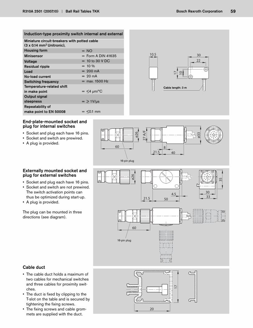
59R310A 2501 (2007.10) Ball Rail Tables TKK Bosch Rexroth Corporation
ø26
335021.5
4.5
60
30
35
16-pin plug
End-plate-mounted socket and plug for internal switches• Socket and plug each have 16 pins.• Socket and switch are prewired.• A plug is provided.
16-pin plug
Externally mounted socket and plug for external switches• Socket and plug each have 16 pins.• Socket and switch are not prewired.
The switch activation points can thus be optimized during start-up.
• A plug is provided.
The plug can be mounted in three directions (see diagram).
Cable duct• The cable duct holds a maximum of
two cables for mechanical switches and three cables for proximity swit-ches.
• The duct is fi xed by clipping to the T-slot on the table and is secured by tightening the fi xing screws.
• The fi xing screws and cable grom-mets are supplied with the duct.
17
20
27 A
/F
ø33
4021.58
ø26
60
Miniature circuit-breakers with potted cable(3 x 0.14 mm2 Unitronic), Housing formMinisensorVoltageResidual rippleLoadNo-load currentSwitching frequencyTemperature-related shiftin make pointOutput signalsteepnessRepeatability ofmake point to EN 50008
Induction-type proximity switch internal and external
Cable length: 3 m
= NO= Form A DIN 41635= 10 to 30 V DC= 10 %= 200 mA= 20 mA= max. 1500 Hz
= <4 μm/ºC = > 1V/μs
= <0.1 mm
3022
17 10
10.5

60 Ball Rail Tables TKK R310A 2501 (2007.10)Bosch Rexroth Corporation
MotorsDimensions of AC Servomotors
MHD 71A-061-NG1-UN Part number 8611-061-03
MHD 71B-061-NG1-UN Part number 8611-062-03
MKD 41B-144 KG1 Part number 8611-010-03
MKD 71B-N-061 KG1 Part number 8611-011-03
MHD 90B-047-NG1-UN Part number 8611-063-03 MKD 90B-047 KG1 Part number 8611-013-03
For the data of the AC servomotors, see “Motor Data” and catalog “Controllers, Motors, Electrical Accessories” RE 82 701.
Ø11
0 j6
4
31214
Ø24
k6
14011
165
50
45° 45°
8
45° 45°
30
2.5
Ø50
j6
Ø14
k6
826.6
243
95
9.5
40
3
Ø95
j6
Ø19
k6
264
45° 45°
115
9
130
9.5
45° 45°
40
3
Ø95
j6
Ø19
k6
115
9
130
205
9.5
40
3
Ø95
j6
Ø19
k6
264
45° 45°
115
9
130
Ø11
0 j6
4
31214
Ø24
k6
14011
165
50
45° 45°

61R310A 2501 (2007.10) Ball Rail Tables TKK Bosch Rexroth Corporation
The motors can be supplied as complete units with control system. For further details on the motors and controllers, see catalog RE 82 701. Drawings to different scales.
Dimensions of MiniDrive
MMD 082A-030-EG1-CN Part number 8611-060-03
808
35 177.5
3
ø70 h
7ø1
9 h6 90
6
45° 45°
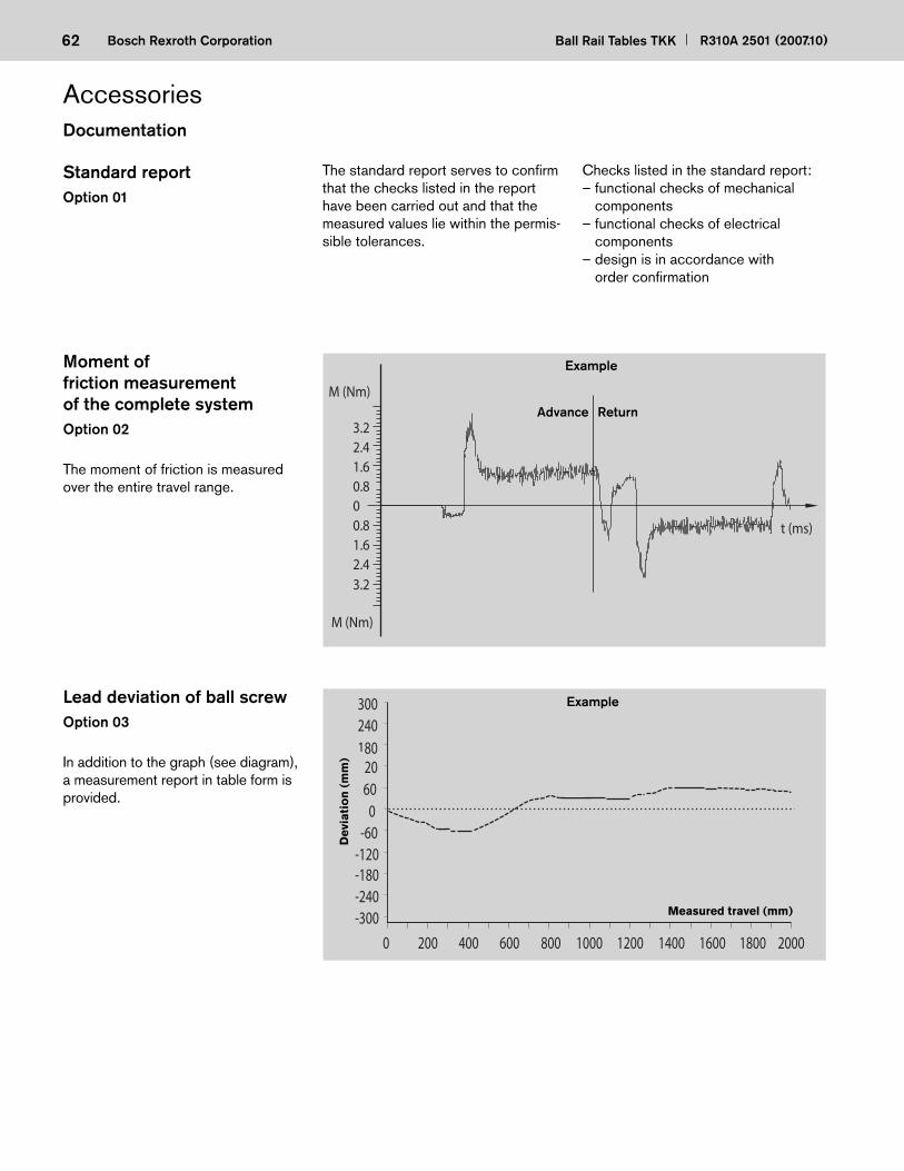
62 Ball Rail Tables TKK R310A 2501 (2007.10)Bosch Rexroth Corporation
-300200 400 600 800 1000 1200 1400 1600 1800 20000
300
-240
240
-180
180
-120
120
-60
60 0
3.22.41.60.800.81.62.43.2
M (Nm)
M (Nm)
t (ms)
Standard reportOption 01
The standard report serves to confi rm that the checks listed in the report have been carried out and that the measured values lie within the permis-sible tolerances.
Checks listed in the standard report:– functional checks of mechanical
components– functional checks of electrical
components– design is in accordance with
order confi rmation
Lead deviation of ball screwOption 03
In addition to the graph (see diagram), a measurement report in table form is provided.
Moment of friction measurement of the complete systemOption 02
The moment of friction is measured over the entire travel range.
Dev
iati
on
(m
m)
Advance Return
Measured travel (mm)
Example
Example
Documentation
Accessories

63R310A 2501 (2007.10) Ball Rail Tables TKK Bosch Rexroth Corporation
Sequence accuracyOption 04
Several measuring points are passed during the total travel.The following deviations are permitted:
PitchingPitching means angular deviation about the horizontal axis. This angular devia-tion is converted into a linear deviation in mm on the basis of a standard length and is plotted on thgraph.
YawingYawing is angular deviation about the vertical axis. This angular deviation is converted to a linear deviation in mm on the basis of a standard length and is plotted on the graph.
110 220 330 440 5500
-1.0
1.5
-0.5
0.50.0
2.02.53.0
-5.0
-3.0
-4.5
-3.5-4.0
-2.5-2.0
Dev
iati
on
(m
m)
Measured travel (mm)
110 220 330 440 550
-1.0
1.5
-0.5
0.5
0.0
-1.5
-2.0
-2.5
-3.0
0
-4.0
-3.5
-4.5
-5.0
-5.5-6.0
Dev
iati
on
(m
m)
Measured travel (mm)
Example
Example
In addition to graphical representation (see illustrations), a measurement report is supplied in table form.
“Yawing”
Vertical axis
Positioning movement
“Pitching”
Horizontal axis
Positioning movement
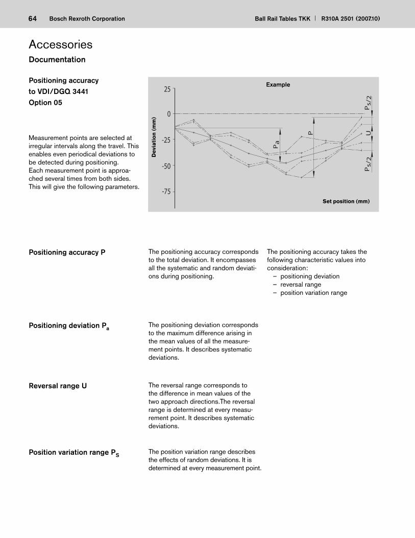
64 Ball Rail Tables TKK R310A 2501 (2007.10)Bosch Rexroth Corporation
Positioning accuracyto VDI/DGQ 3441Option 05
Measurement points are selected at irregular intervals along the travel. This enables even periodical deviations to be detected during positioning.Each measurement point is approa-ched several times from both sides.This will give the following parameters.
Positioning accuracy P The positioning accuracy corresponds to the total deviation. It encompasses all the systematic and random deviati-ons during positioning.
The positioning accuracy takes the follow ing characteristic values into consideration: – positioning deviation – reversal range – position variation range
Positioning deviation Pa The positioning deviation corresponds to the maximum difference arising in the mean values of all the measure-ment points. It describes systematic deviations.
Reversal range U The reversal range corresponds to the difference in mean values of the two approach directions.The reversal range is determined at every measu-rement point. It describes systematic deviations.
Position variation range PS The position variation range describes the effects of random deviations. It is determined at every measurement point.
Dev
iati
on
(m
m)
Example
Set position (mm)
25
0
-25
-50
-75
Ps/
2U
Pa
P
Ps/
2
Documentation
Accessories

65R310A 2501 (2007.10) Ball Rail Tables TKK Bosch Rexroth Corporation
13
M6
10
8
6 10
8
6
9
1320
M6
17
7
3.6
20
M8
8
+2
-110
128.8
M10
19
19
(app
r. 2.
7)
(appr. 25)
TKK 15-155 Al TKK 20-225 Al TKK 30-325 Al
TKK 35-455 Al
Spring ball
Part number8447-001-01
T-nut
Part number0391-750-03
T-nut
Part number8447-010-02
T-nut
Part number8447-006-01
T-nut
Part number8454-030-49
Fixing spring forT-nut 8447-006-01
Mounting accessories

66 Ball Rail Tables TKK R310A 2501 (2007.10)Bosch Rexroth Corporation
Connection System
Rexroth cross plates are used for simple construction of X-Y units. They are supplied as complete assemblies with all screws, pins and T-nuts necessary for joining the two axes together.
The connection system is designed so that ball rail tables of both identical ...
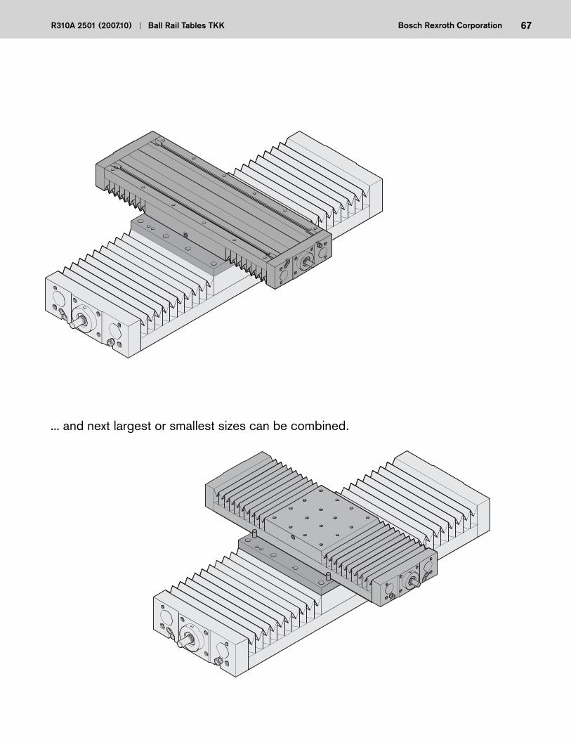
67R310A 2501 (2007.10) Ball Rail Tables TKK Bosch Rexroth Corporation
... and next largest or smallest sizes can be combined.
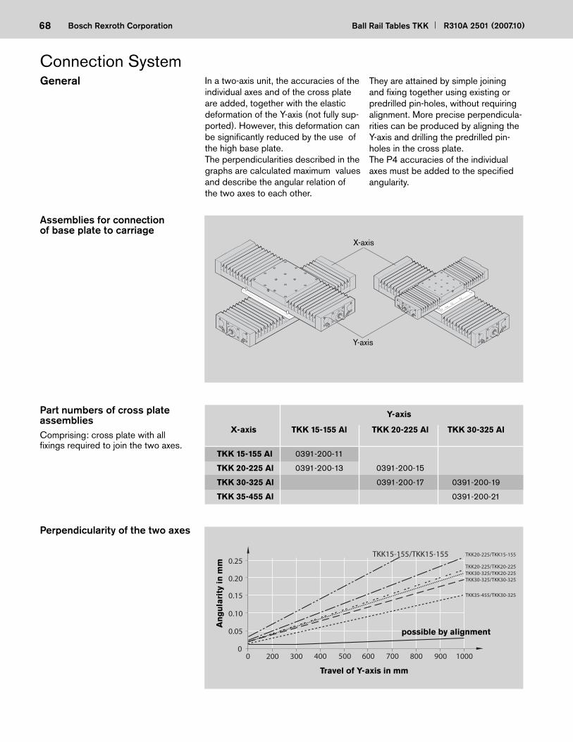
68 Ball Rail Tables TKK R310A 2501 (2007.10)Bosch Rexroth Corporation
Assemblies for connection of base plate to carriage
Y-axis
X-axis
Perpendicularity of the two axes
Part numbers of cross plate assembliesComprising: cross plate with all fi xings required to join the two axes.
0
0.05
0.10
0.15
0.20
0 200 300 400 500 600 700 800 900 1000
TKK15-155/TKK15-155 TKK20-225/TKK15-155
TKK20-225/TKK20-225
TKK35-455/TKK30-325
TKK30-325/TKK20-225TKK30-325/TKK30-325
0.25
possible by alignment
Travel of Y-axis in mm
An
gu
lari
ty in
mm
General In a two-axis unit, the accuracies of the individual axes and of the cross plate are added, together with the elastic deformation of the Y-axis (not fully sup-ported). However, this deformation can be signifi cantly reduced by the use of the high base plate. The perpendicularities described in the graphs are calculated maximum values and describe the angular relation of the two axes to each other.
Y-axis
X-axis TKK 15-155 Al TKK 20-225 Al TKK 30-325 Al
TKK 15-155 Al 0391-200-11
TKK 20-225 Al 0391-200-13 0391-200-15
TKK 30-325 Al 0391-200-17 0391-200-19
TKK 35-455 Al 0391-200-21
Connection System They are attained by simple joining and fi xing together using existing or predrilled pin-holes, without requiring alignment. More precise perpendicula-rities can be produced by aligning the Y-axis and drilling the pre drilled pin-holes in the cross plate. The P4 accuracies of the individual axes must be added to the specifi ed angularity.

69R310A 2501 (2007.10) Ball Rail Tables TKK Bosch Rexroth Corporation
Assemblies for connection of carriage to carriage
Y-axis
X-axis
Y-axis
X-axis TKK 15-155 Al TKK 20-225 Al TKK 30-325 Al with LT = 220 with LT = 320 with LT = 450
TKK 15-155 Al 0391-200-12
TKK 20-225 Al 0391-200-14 0391-200-16
TKK 30-325 Al 0391-200-18 0391-200-20
TKK 35-455 Al 0391-200-22
Part numbers of cross plate assembliesComprising: cross plate with all fi xings required to join the two axes.
Perpendicularity of the two axes
TKK15-155/TKK15-155
TKK20-225/TKK15-155TKK20-225/TKK20-225
TKK35-455/TKK30-325
TKK30-325/TKK30-325TKK30-325/TKK20-225
0
0.10
0.15
0.20
0.25
0 200 300 400 500 600 700 800 900 1000
0.05
Travel of Y-axis in mm
An
gu
lari
ty in
mm
possible by alignment
Note Fully assembled cross plates and combinations of steel ball rail tables available on request. In the case of motor attachment via side drive with timing belt, the motor may project into the working area of adjacent axes. Check interference edges.
LT = Carriage length
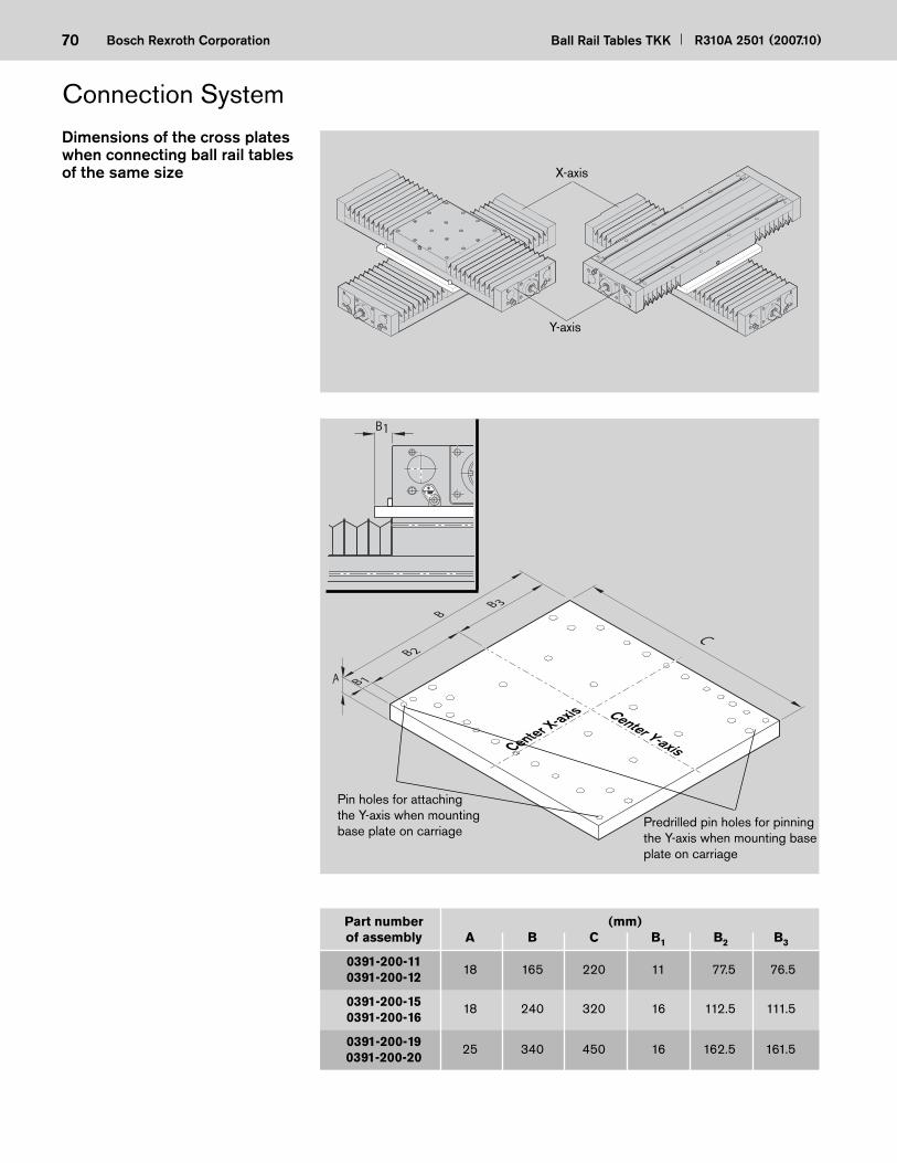
70 Ball Rail Tables TKK R310A 2501 (2007.10)Bosch Rexroth Corporation
Dimensions of the cross plates when connecting ball rail tables of the same size
Part number (mm) of assembly A B C B1 B2 B3
0391-200-11 0391-200-12
0391-200-15 0391-200-16
0391-200-19 0391-200-20
B1
C
B 1
B 2
B 3
A
B
Pin holes for attaching the Y-axis when mounting base plate on carriage
Center Y-axisCenter X-axis
X-axis
Y-axis
Predrilled pin holes for pin ning the Y-axis when mounting base plate on carriage
Connection System
18 165 220 11 77.5 76.5
18 240 320 16 112.5 111.5
25 340 450 16 162.5 161.5

71R310A 2501 (2007.10) Ball Rail Tables TKK Bosch Rexroth Corporation
Part number (mm) of assembly A B C B1 B2 B3
0391-200-13 0391-200-14
0391-200-17 0391-200-18
0391-200-21 0391-200-22
18 220 220 32.5 77.5 110
18 320 320 47.5 112.5 160
25 400 450 37.5 162.5 200
C
B 1
B 2
B 3
A
B
Pin holes for attaching the Y-axis when mounting base plate on carriage
Center Y-axisCenter X-axis
X-axis
Y-axis
Dimensions of the cross plates when connecting ball rail tables of adjacent sizes
Predrilled pin holes for pin ning the Y-axis when mounting base plate on
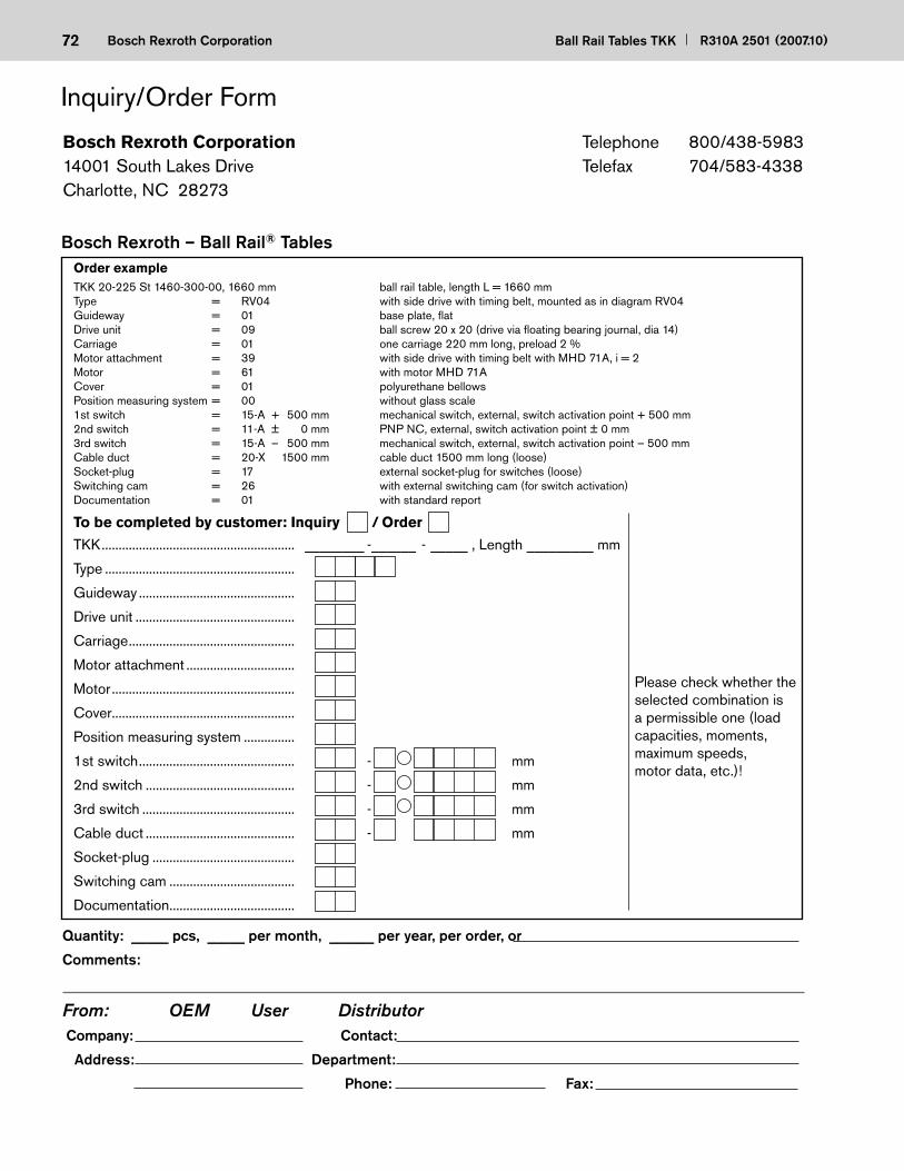
72 Ball Rail Tables TKK R310A 2501 (2007.10)Bosch Rexroth Corporation
Order exampleTKK 20-225 St 1460-300-00, 1660 mm ball rail table, length L = 1660 mmType = RV04 with side drive with timing belt, mounted as in diagram RV04Guideway = 01 base plate, fl atDrive unit = 09 ball screw 20 x 20 (drive via fl oating bearing journal, dia 14)Carriage = 01 one carriage 220 mm long, preload 2 %Motor attachment = 39 with side drive with timing belt with MHD 71A, i = 2Motor = 61 with motor MHD 71ACover = 01 polyurethane bellowsPosition measuring system = 00 without glass scale1st switch = 15-A + 500 mm mechanical switch, external, switch activation point + 500 mm2nd switch = 11-A ± 0 mm PNP NC, external, switch activation point ± 0 mm3rd switch = 15-A – 500 mm mechanical switch, external, switch activation point – 500 mmCable duct = 20-X 1500 mm cable duct 1500 mm long (loose)Socket-plug = 17 external socket-plug for switches (loose)Switching cam = 26 with external switching cam (for switch activation)Documentation = 01 with standard report
To be completed by customer: Inquiry / Order
Bosch Rexroth – Ball Rail® Tables
TKK ......................................................... ________ - ______ - _____ , Length _________ mm
Type ........................................................
Guideway ..............................................
Drive unit ...............................................
Carriage .................................................
Motor attachment ................................
Motor ......................................................
Cover ......................................................
Position measuring system ...............
1st switch .............................................. - mm
2nd switch ............................................ - mm
3rd switch ............................................. - mm
Cable duct ............................................ - mm
Socket-plug ..........................................
Switching cam .....................................
Documentation .....................................
Bosch Rexroth Corporation14001 South Lakes DriveCharlotte, NC 28273
Telephone 800/438-5983Telefax 704/583-4338
Please check whether the selected combination is a permissible one (load capacities, moments, maximum speeds, motor data, etc.)!
Inquiry/Order Form
Quantity: _____ pcs, _____ per month, ______ per year, per order, or
Comments:
From: OEM User Distributor Company: Contact:
Address: Department:
Phone: Fax:

73R310A 2501 (2007.10) Ball Rail Tables TKK Bosch Rexroth Corporation
Notes

74 Ball Rail Tables TKK R310A 2501 (2007.10)Bosch Rexroth Corporation
Notes

Bosch Rexroth CorporationCorporate Headquarters5150 Prairie Stone ParkwayHoffman Estates, IL 60192-3707Telephone (847) 645-3600Facsimile (847) 645-6201
Bosch Rexroth CorporationIndustrial Hydraulics2315 City Line RoadBethlehem, PA 18017-2131Telephone (610) 694-8300Facsimile (610) 694-8467
Bosch Rexroth CorporationElectric Drives and Controls5150 Prairie Stone ParkwayHoffman Estates, IL 60192-3707Telephone (847) 645-3600Facsimile (847) 645-6201
Bosch Rexroth CorporationPneumatics1953 Mercer RoadLexington, KY 40511-1021Telephone (859) 254-8031Facsimile (859) 281-3491
Bosch Rexroth CorporationMobile Hydraulics1700 Old Mansfield RoadWooster, OH 44691-0394Telephone (330) 263-3300Facsimile (330) 263-3333
Printed in the United StatesR310A 501
Bosch Rexroth CorporationLinear Motion andAssembly Technologies14001 South Lakes DriveCharlotte, NC 28273Telephone (800) 438-5983Facsimile (704) 583-0523www.boschrexroth-us.com