Embed Size (px)
Citation preview

Ball SplineSBSP

2

Structure 2
Advantages 2
Typenschlüssel 3
Data sheets 4-11 • Ball Splines with cylindrical nuts 4-5 • Ball Splines with flange type nuts 6-7 • Ball Splines with flange type nuts and limited stroke 8-9 • Ball Splines with rotary type nuts 10-11
Precision 12-13 Preload 14 Shaft options 15 • Hollow shaft 15 • Maximum length 15
Material / Coating 16
1

NTN-SNR Ball Splines BSP
NTN-SNR Ball Spline BSP are linear guides on shafts with raceways. The shafts, with the accurate grinded raceways in combination with ball nuts, are able to transfer rotations and also linear strokes. They are suitable for high linear speeds and high rotation speeds.
Structure
Ball cage
Balls
Shaft
Locking ring with seals
Nut body
Advantages
•High load capacity
By a defined relationship between race way radius and ball diameter, the contact surfaces significantly
increase. This allows, unlike conventional sliding guides, very high load ratings with minimum dimensions
and long service life time.
•Torque and force transmission
The design principle of the Ball Splines allow the transmission of forces, tilting and rotation moments by
simultaneous linear motions.
•Wide range of applications
The combination of an extremely accurate grinded profile rail, the runner block and precision ball screw.
The wide product range with shaft diameters from 4 mm up to 100 mm in combination with different nut
designs, results in a wide variety of applications in industrial automation.
•Customized machining
It is easy to produce Ball Splines according to customers drawing.
2

BSP 25 FN 1 UU L 0500 N Z1 - N 1 2 3 4 5 6 7 8 9 10
Type code
1 BSP Serie
2 25 Size
3 FN Nut type
4 1 Number of nuts
5 UUSealsUU: with seals AA: without seals
6 LShaft typeL: Solid shaft K: Hollow shaft
7 0500 Shaft length
8 NPrecision classN: Normal precision P: P - precision
9 Z1Precision classZ0: without preload Z1: low preloadZ2: medium preload
10 NSpecialN: Standard S: special version
11 03Greasestipulated in the catalog Ball rail systems page 77
12 00 Grease connection
13 1Nut materialsee materials and coatings
14 0
Special nuts0 Without special optionsA…Z According to a drawing or text description
(Index is given in case of an order issued)
15 1Shaft materialsee materials and coatings
16 A...Z
Special shafts0 Without special optionsA…Z According to a drawing or text description
(Index is given in case of an order issued)
Example for standard without options and machining:
BSP 25 FN 1 UU L 0500 N Z1 - S - 03 00 1 0 - 1 0 1 2 3 4 5 6 7 8 9 10 11 12 13 14 15 16
Example special with options and / or machining:
3

Data sheets
Ball Splines with cylindrical nuts
MO1
MO1
L
DDs
b
tKey groovet
b
Key groove
L1
(L)
B
DDs
b
t
2-ødGrease hole
2-ødGrease hole
2-ød
BSP04……10 BSP13……60
Key groove
SSP80.80L~100.100L
L1
Grease hole
TypeDimension
mmøD h6 L B b t L1 d Ds h7
BSP 04 CN 10 160
-0,2-- 2.0
+0,014 0
1.2+0,05
06.0 -- 4
BSP 06 CN 14 250
-0,2-- 2.5
+0,014 0
1.2+0,05
010.5 1.0 6
BSP 08 CN 16 250
-0,2-- 2.5
+0,014 0
1.2+0,05
010.5 1.5 8
BSP 10 CN 21 330
-0,2-- 3.0
+0,014 0
1.5+0,05
013.0 1.5 10
BSP 13 CN 24 360
-0,2-- 3.0
+0,014 0
1.5+0,05
015.0 1.5 13
BSP 16 CN 31 500
-0,2-- 3.5
+0,018 0
2.0+0,05
017.5 2.0 16
BSP 20 CN 35 630
-0,2-- 4.0
+0,018 0
2.5+0,05
029.0 2.0 20
BSP 25 CN 42 710
-0,3-- 4.0
+0,018 0
2.5+0,05
036.0 3.0 25
BSP 30 CN 47 800
-0,3-- 4.0
+0,018 0
2.5+0,05
042.0 3.0 30
BSP 40 CN 64 1000
-0,3-- 6.0
+0,018 0
3.5+0,05
052.0 4.0 40
BSP 50 CN 80 1250
-0,3-- 8.0
+0,022 0
4.0+0,05
058.0 4.0 50
BSP 60 CN 90 1400
-0,3-- 12.0
+0,027 0
5.0+0,05
067.0 4.0 60
BSP 80 CN 120 160 -- 118.2 16.0+0,027
06.0
+0,05 0
76.0 5.0 80
BSP 80 CL 120 217 -- 175.2 16.0+0,027
06.0
+0,05 0
110.0 5.0 80
BSP 100 CN 150 185 -- 132.6 20.0+0,033
07.0
+0,05 0
110.0 5.0 100
BSP 100 CL 150 248 -- 195.6 20.0+0,033
07.0
+0,05 0
160.0 5.0 100
4

MO1
MO1
L
DDs
b
tKey groovet
b
Key groove
L1
(L)
B
DDs
b
t
2-ødGrease hole
2-ødGrease hole
2-ød
BSP04……10 BSP13……60
Key groove
SSP80.80L~100.100L
L1
Grease hole
MO2
Allowable static moment for two nuts on block
Torque moment
Load rating Allowable static
moment
Cross-sectional
moment of inertia
Cross-sectional
coefficient
Weight Type
kNm kN kNm mm4 mm3 kgNut Shaft
CT C0T C C0 M01 M02 kg kg/m
0.00074 0.00105 0.86 1.22 0.002 0.010 11.80 5.90 0.0065 0.10 BSP 04 CN
0.0015 0.0024 1.22 2.28 0.005 0.040 59.00 19.70 0.019 0.21 BSP 06 CN
0.0021 0.0037 1.45 2.87 0.007 0.050 1,90x10² 47.60 0.023 0.38 BSP 08 CN
0.0044 0.0082 2.73 5.07 0.018 0.116 4,61x10² 92.20 0.054 0.60 BSP 10 CN
0.021 0.039 2.67 4.89 0.014 0.109 1,38x10³ 2,13x10² 0.07 1.0 BSP 13 CN
0.060 0.110 6.12 11.2 0.046 0.299 2,98x10³ 3,73x10² 0.15 1.5 BSP 16 CN
0.105 0.194 8.90 16.3 0.110 0.560 7,35x10³ 7,34x10² 0.22 2.4 BSP 20 CN
0.189 0.346 12.8 23.4 0.171 1.029 1,79x10⁴ 1,43x10³ 0.33 3.7 BSP 25 CN
0.307 0.439 18.6 23.2 0.181 1.470 3,66x10⁴ 2,44x10³ 0.36 5.4 BSP 30 CN
0.674 0.934 30.8 37.5 0.358 2.940 1,55x10⁵ 5,75x10³ 0.95 9.6 BSP 40 CN
1.291 2.955 40.3 64.9 0.690 4.084 2,83x10⁵ 1,13x10⁴ 1.90 15.0 BSP 50 CN
1.577 2.629 47.7 79.5 0.881 5.473 5,91x10⁵ 1,97x10⁴ 2.30 21.6 BSP 60 CN
3.860 6.230 83.1 134.0 2.00 11.10 1,93x10⁶ 4,38x10⁴ 5.10 39.0 BSP 80 CN
5.120 9.340 110.0 201.0 4.41 21.10 1,93x10⁶ 4,38x10⁴ 7.60 39.0 BSP 80 CL
6.750 11.570 135.0 199.0 3.36 19.30 4,69x10⁶ 9,38x10⁴ 9.70 61.0 BSP 100 CN
8.960 17.300 179.0 298.0 7.34 37.70 4,69x10⁶ 9,38x10⁴ 13.90 61.0 BSP 100 CL
5

Ball Splines with flange type nuts
TypeDimension
mmøD h6 L Df H P.C.D. d1xd2xh W d Ds h7
BSP 06 FN 14 250
-0,230 5 22 3,4x6,5x3,3 7.5 1.0 6
BSP 08 FN 16 250
-0,232 5 24 3,4x6,5x3,3 7.5 1.5 8
BSP 10 FN 21 330
-0,242 6 32 4,5x8,0x4,4 10.5 1.5 10
BSP 13 FN 24 360
-0,243 7 33 4,5x8,0x4,4 11.0 1.5 13
BSP 16 FN 31 500
-0,250 7 40 4,5x8,0x4,4 18.0 2.0 16
BSP 20 FN 35 630
-0,258 9 45 5,5x9,5x5,4 22.5 2.0 20
BSP 25 FN 42 710
-0,365 9 52 5,5x9,5x5,4 26.5 3.0 25
BSP 30 FN 47 800
-0,375 10 60 6,6x11,0x6,5 30.0 3.0 30
BSP 40 FN 64 1000
-0,3100 14 82 9,0x14,0x8,6 36.0 4.0 40
BSP 50 FN 80 1250
-0,3124 16 102 11,0x17,5x11,0 46.5 4.0 50
BSP 60 FN 90 1400
-0,3129 18 107 11,0x17,5x11,0 52.0 4.0 60
MO1
L
H Wh
Df D
d2
d1
P.C
.D.
Ds
Fixing hole x 4
2-ødGrease hole
2-ødGrease hole
BSP13……60 BSP06……10
6
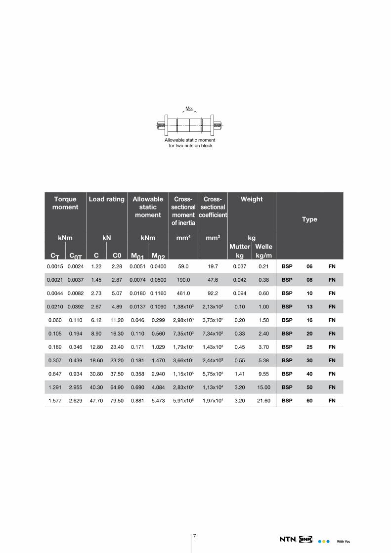
MO2
Allowable static moment for two nuts on block
Torque moment
Load rating Allowable static
moment
Cross-sectionalmoment of inertia
Cross-sectional
coefficient
Weight
Type
kNm kN kNm mm4 mm3 kgMutter Welle
CT C0T C C0 M01 M02 kg kg/m
0.0015 0.0024 1.22 2.28 0.0051 0.0400 59.0 19.7 0.037 0.21 BSP 06 FN
0.0021 0.0037 1.45 2.87 0.0074 0.0500 190.0 47.6 0.042 0.38 BSP 08 FN
0.0044 0.0082 2.73 5.07 0.0180 0.1160 461.0 92.2 0.094 0.60 BSP 10 FN
0.0210 0.0392 2.67 4.89 0.0137 0.1090 1,38x10³ 2,13x10² 0.10 1.00 BSP 13 FN
0.060 0.110 6.12 11.20 0.046 0.299 2,98x10³ 3,73x10² 0.20 1.50 BSP 16 FN
0.105 0.194 8.90 16.30 0.110 0.560 7,35x10³ 7,34x10² 0.33 2.40 BSP 20 FN
0.189 0.346 12.80 23.40 0.171 1.029 1,79x10⁴ 1,43x10³ 0.45 3.70 BSP 25 FN
0.307 0.439 18.60 23.20 0.181 1.470 3,66x10⁴ 2,44x10³ 0.55 5.38 BSP 30 FN
0.647 0.934 30.80 37.50 0.358 2.940 1,15x10⁵ 5,75x10³ 1.41 9.55 BSP 40 FN
1.291 2.955 40.30 64.90 0.690 4.084 2,83x10⁵ 1,13x10⁴ 3.20 15.00 BSP 50 FN
1.577 2.629 47.70 79.50 0.881 5.473 5,91x10⁵ 1,97x10⁴ 3.20 21.60 BSP 60 FN
7
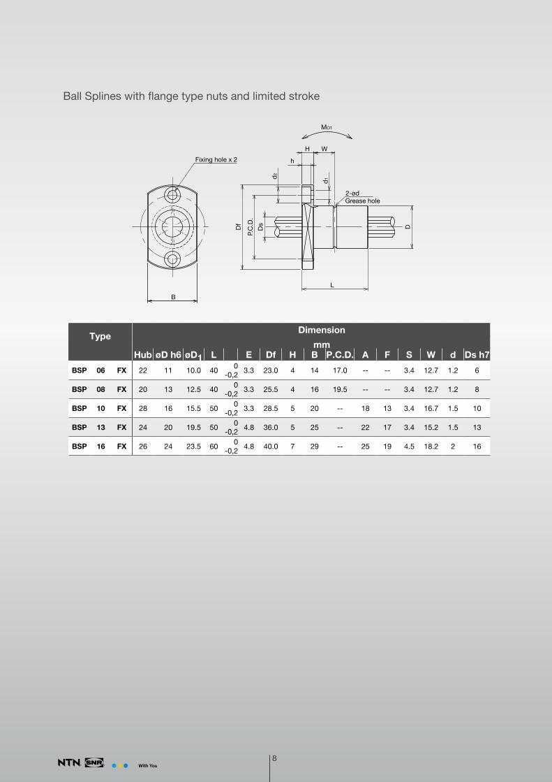
Ball Splines with flange type nuts and limited stroke
TypeDimension
mmHub øD h6 øD1 L E Df H B P.C.D. A F S W d Ds h7
BSP 06 FX 22 11 10.0 400
-0,23.3 23.0 4 14 17.0 -- -- 3.4 12.7 1.2 6
BSP 08 FX 20 13 12.5 400
-0,23.3 25.5 4 16 19.5 -- -- 3.4 12.7 1.2 8
BSP 10 FX 28 16 15.5 500
-0,23.3 28.5 5 20 -- 18 13 3.4 16.7 1.5 10
BSP 13 FX 24 20 19.5 500
-0,24.8 36.0 5 25 -- 22 17 3.4 15.2 1.5 13
BSP 16 FX 26 24 23.5 600
-0,24.8 40.0 7 29 -- 25 19 4.5 18.2 2 16
MO1
L
H W
h
Df D
d2
d1
P.C
.D.
Ds
B
Fixing hole x 2
2-ødGrease hole
8

MO2
Allowable static moment for two nuts on block
Torque moment
Load rating Allowable static
moment
Cross-sectionalmoment of inertia
Cross-sectional
coefficient
Gewicht Type
kNm kN kNm mm4 mm3 kgNut Shaft
CT C0T C C0 M01 M02 kg kg/m
0.0023 0.0038 1.80 3.00 0.0112 0.0450 59.0 19.7 0.000 0.210 BSP 06 FX
0.0033 0.0055 2.02 3.37 0.0131 0.0520 190.0 47.6 0.027 0.380 BSP 08 FX
0.0065 0.0109 3.21 5.35 0.0256 0.1020 461.0 92.2 0.048 0.600 BSP 10 FX
0.0276 0.0507 4.15 7.60 0.0388 0.1550 1,38x10³ 2,13x10² 0.075 1.000 BSP 13 FX
0.0628 0.1150 7.66 14.00 0.0883 0.3530 2,98x10³ 3,73x10² 0.123 1.500 BSP 16 FX
9

Ball Splines with rotary type nuts
4-S
4-d
LH l
h
DS
D2
P1
D1
P2
D3
MO
6-S deep h
6-d G deep FGrease hole from the back side
G deep FGrease hole from the back side
θ°60°θ°
BSP06……10RN BSP13……60RN
TypeDimension
mm °øD1 h6 øD2 L P1 S h l H B1 øD3 h7 P2 d G F øDs h7 Θ
BSP 06 RN 20.0 13 -- 250
-0,216 M 2 2.5 5.0 6.5 -- 30 24 2.4 M 3 2.6 6 20
BSP 08 RN 22.0 15 -- 250
-0,218 M 2,5 3.0 6.0 6.5 -- 33 27 2.9 M 3 2.6 8 20
BSP 10 RN 27.0 19 -- 330
-0,222 M 3 4.0 8.0 7.0 -- 40 33 3.4 M 3 2.8 10 20
BSP 13 RN 29.0 24 -- 360
-0,224 M 3 5.0 8.0 9.0 -- 50 42 3.4 M 3 3.6 13 15
BSP 16 RN 36.0 31 -- 500
-0,230 M 4 6.0 10.0 11.0 -- 60 50 4.5 M 3 4.4 16 15
BSP 16 RL 39.5 520
-0,00750 -- 32 M 5 8.0 10.0 5.0 37 68 60 4.5 -- -- 16 --
BSP 20 RN 44.0 35 -- 630
-0,238 M 4 7.0 12.0 13.0 -- 72 62 4.5 M 6 x 0,75 5.2 20 15
BSP 20 RL 43.5 560
-0,00763 -- 36 M 5 8.0 12.0 6.0 48 72 64 4.5 -- -- 20 --
BSP 25 RN 55.0 42 -- 710
-0,347 M 5 8.0 13.0 16.0 -- 82 72 4.5 M 6 x 0,75 6.4 25 15
BSP 25 RL 53.0 620
-0,00771 -- 45 M 6 8.0 13.0 6.0 55 78 70 4.5 -- -- 25 --
BSP 30 RN 61.0 47 -- 800
-0,352 M 6 10.0 17.0 17.0 -- 100 86 6.6 M 6 x 0,75 6.8 30 15
BSP 40 RN 76.0 64 -- 1000
-0,366 M 6 10.0 23.0 20.0 -- 120 104 9.0 M 6 x 0,75 8.0 40 15
BSP 50 RN 92.0 80 -- 1250
-0,380 M 8 13.0 24.0 22.0 -- 134 118 9.0 M 6 x 0,75 8.8 50 15
BSP 60 RN 107.0 90 -- 1400
-0,395 M 8 13.0 25.0 25.0 -- 155 137 9.0 M 6 x 0,75 10.0 60 15
10

Torque moment
Ball Spline
Load rating
Ball Spline
Load rating
cross roller bearing
Allowable static
moment
Cross-sec-tional
moment of inertia
Cross- sectional
coefficient
Weight max. rpm
Type
kNm kN kN kNm mm4 mm3 kg min-1
Nut Shaft CT C0T C C0 C C0 M0 kg kg/m
0.0015 0.0024 1.22 2.28 0.60 0.50 0.0051 59.0 19.7 0.04 0.21 2 940 BSP 06 RN
0.0021 0.0037 1.45 2.87 1.20 1.10 0.0074 190.0 47.6 0.05 0.38 2 580 BSP 08 RN
0.0044 0.0082 2.73 5.07 2.40 2.45 0.0180 461.0 92.2 0.09 0.60 2 060 BSP 10 RN
0.0210 0.0392 2.67 4.89 2.90 3.70 0.0180 1,38x10³ 2,13x10² 0.17 1.00 1 350 BSP 13 RN
0.0600 0.1100 6.12 11.20 5.60 6.70 0.0460 2,98x10³ 3,73x10² 0.33 1.50 1 080 BSP 16 RN
0.0600 0.1100 6.12 11.20 13.00 12.80 0.0460 2,98x10³ 3,73x10² 0.45 1.50 4 000 BSP 16 RL
0.105 0.194 8.90 16.30 6.55 8.79 0.0630 7,35x10³ 7,34x10² 0.57 2.40 890 BSP 20 RN
0.1050 0.7940 8.90 16.30 17.40 17.20 0.1100 2,98x10³ 3,73x10² 0.69 2.40 3 600 BSP 20 RL
0.189 0.346 12.80 23.40 9.63 12.70 0.1710 1,79x10⁴ 1,43x10³ 0.81 3.70 700 BSP 25 RN
0.1890 0.3460 12.80 23.40 22.10 22.50 0.1710 2,98x10³ 3,73x10² 0.92 3.70 3 200 BSP 25 RL
0.307 0.439 18.60 23.20 11.80 17.10 0.1810 3,66x10⁴ 2,44x10³ 1.19 5.38 640 BSP 30 RN
0.674 0.934 30.80 37.50 23.00 32.30 0.3580 1,15x10⁵ 5,75x10³ 2.25 9.55 510 BSP 40 RN
1.291 2.955 40.30 64.90 27.80 44.00 0.6900 2,83x10⁵ 1,13x10⁴ 3.57 15.00 430 BSP 50 RN
1.577 2.629 47.70 79.50 29.00 48.80 0.8810 5,91x10⁵ 1,97x10⁴ 5.03 21.60 370 BSP 60 RN
11

Precision
• Ball Splines of the types BSP…CN / CL, BSP…FN and BSP…BN are available in normal precision and
P - precision.
•The Ball Splines of the types BSP…RN / RL and BSP…FX are only available in normal precision.
j A-B
Al A-B
B
j A-B
k A-Bm A-B
k A-B
Shaft extension for part assembling
Bearing seat
nut
ShaftBearing seat
Shaft extension for part assembling
Type
Radial run-out of the bearing seats
Perpendicularity of the end of the spline
shaft section
Perpendicularity ofthe flange
µm µm µm
Normal- Precision
P - PrecisionNormal-
PrecisionP - Precision
Normal- Precision
P - Precision
BSP 04 14 8 9 6 -- --
BSP 06 14 8 9 6 11 8
BSP 08 14 8 9 6 11 8
BSP 10 17 10 9 6 13 9
BSP 13 19 12 11 8 13 9
BSP 16 19 12 11 8 13 9
BSP 20 19 12 11 8 13 9
BSP 25 22 13 13 9 16 11
BSP 30 22 13 13 9 16 11
BSP 40 25 15 16 11 19 13
BSP 50 25 15 16 11 19 13
BSP 60 29 17 19 13 22 15
BSP 80 29 17 19 13 -- --
BSP 100 34 20 22 15 -- --
12

Type
Radial run-out of outer surface of nut relative to shaft support area (Max.) [µm]
Shaft length [mm]
up to 200
> 200 up to 315
> 315 up to 400
> 400 up to 500
> 500 up to 630
> 630 up to 800
> 800 up to 1.000
> 1.000 up to 1.250
> 1.250 up to 1.600
> 1.600 up to 2.000
BSP 04Normal- Präzision 46 89 126 -- -- -- -- -- -- --
P - Präzision 26 57 82 -- -- -- -- -- -- --
BSP 06Normal- Präzision 46 89 126 -- -- -- -- -- -- --
P - Präzision 26 57 82 -- -- -- -- -- -- --
BSP 08Normal- Präzision 46 89 126 163 -- -- -- -- -- --
P - Präzision 26 57 82 108 -- -- -- -- -- --
BSP 10Normal- Präzision 36 54 68 82 102 -- -- -- -- --
P - Präzision 20 32 41 51 65 -- -- -- -- --
BSP 13Normal- Präzision 34 45 53 62 75 92 115 153 195 --
P - Präzision 18 25 31 38 46 58 75 97 127 --
BSP 16Normal- Präzision 34 45 53 62 75 92 115 153 195 --
P - Präzision 18 25 31 38 46 58 75 97 127 --
BSP 20Normal- Präzision 32 39 44 50 57 68 83 102 130 171
P - Präzision 18 21 25 29 34 42 52 65 85 116
BSP 25Normal- Präzision 32 39 44 50 57 68 83 102 130 171
P - Präzision 18 21 25 29 34 42 52 65 85 116
BSP 30Normal- Präzision 32 39 44 50 57 68 83 102 130 171
P - Präzision 18 21 25 29 34 42 52 65 85 116
BSP 40Normal- Präzision 32 36 39 43 47 54 63 76 93 118
P - Präzision 16 19 21 24 27 32 38 47 59 77
BSP 50Normal- Präzision 32 36 39 43 47 54 63 76 93 118
P - Präzision 16 19 21 24 27 32 38 47 59 77
BSP 60Normal- Präzision 30 34 36 38 41 45 51 59 70 86
P - Präzision 16 17 19 21 23 26 30 35 43 54
BSP 80Normal- Präzision 30 34 36 38 41 45 51 59 70 86
P - Präzision 16 17 19 21 23 26 30 35 43 54
BSP 100Normal- Präzision 30 32 34 35 37 40 43 48 55 65
P - Präzision 16 17 17 19 20 22 24 28 33 40
13

Preload
Preload is a description of the radial clearance of Ball Splines. Applied preload eliminates the radial clearance
of the Ball Splines and increases the stiffness. NTN-SNR Ball Splines are available in three preload classes.
Type Preload class
Operation conditions
Without preload Z0
- low load- smooth movement- no alternating load- almost no vibrations and shocks
Low preload Z1
- low torque moments- high position accuracy- alternating load- low vibrations and shocks
Medium preload Z2
- torque moments- overhanging loads- strong alternating loads- vibrations and shocks
TypePreload / Radial clearance
µm
Z0 Z1 Z2BSP 04 -2...+1 -6…-2 --
BSP 06 -2...+1 -6…-2 --
BSP 08 -2...+1 -6…-2 --
BSP 10 -3...+1 -8…-3 --
BSP 13 -3...+1 -8…-3 -13…-8
BSP 16 -3...+1 -8…-3 -13…-8
BSP 20 -4...+2 -12…-4 -20…-12
BSP 25 -4...+2 -12…-4 -20…-12
BSP 30 -4...+2 -12…-4 -20…-12
BSP 40 -6...+3 -18…-6 -30…-18
BSP 50 -6...+3 -18…-6 -30…-18
BSP 60 -6...+3 -18…-6 -30…-18
BSP 80 -6...+3 -18…-6 -30…-18
BSP 100 -8...+4 -24…-8 -40…-24
14

Hollow shaft
Shaft options
Ball Splines are also available in hollow shaft version.
Maximum length
Dsd
TypeMaximum length
Solid shaft Hollow shaft
mm mm
BSP 04 300 300
BSP 06 400 400
BSP 08 500 500
BSP 10 630 600
BSP 13 1 500 1500
BSP 16 1 500 1500
BSP 20 2 000 2000
BSP 25 2 000 2000
BSP 30 2 000 --
BSP 40 2 000 --
BSP 50 2 000 --
BSP 60 2 000 --
BSP 80 2 000 --
BSP 100 2 000 --
Type Shaft diameter Inner diameter cross-sectionalcoefficient
Cross-sectionalmoment of inert
Ds d Z I
mm mm mm3 mm4
BSP 04 4 1.5 5.7 11
BSP 06 6 2.0 19.4 58
BSP 08 8 3.0 46.5 186
BSP 10 10 4.0 89.6 448
BSP 13 13 6.0 193 1 260
BSP 16 16 8.0 348 2 780
BSP 20 20 10.0 686 6 860
BSP 25 25 15.0 1 230 15 400
15

Notes
Material / CoatingNTN-SNR Ball Splines are available with different coatings and partially in stainless versions.
Index in thetype code
Material / Coating Remarks
0 Standard material
1 Stainless version Only for BSP…CN and BSP…FN up to size 25
2 Blackchrome coating
5 DURALLOY TDC® coating From size 25 possible
16

17

DO
C.I_
BS
P_C
AT1
.GB
a -
Cod
e S
AP
313
012
- N
TN-S
NR
cop
yrig
ht in
tern
atio
nal 0
5/20
15 -
Con
cep
tion
: Com
&C
ie -
Prin
ted
in F
ranc
e
This document is the exclusive property of NTN-SNR ROULEMENTS. Any total or partial reproduction hereof without the prior consent of NTN-SNR ROULEMENTS is strictly prohibited. Legal action may be brought against anyone breaching the terms of this paragraph.
NTN-SNR ROULEMENTS shall not be held liable for any errors or omissions that may have crept into this document despite the care taken in drafting it. Due to our policy of continuous research and development, we reserve the right to make changes without notice to all or part of the products and specifications mentioned in this document.
© NTN-SNR ROULEMENTS, international copyright 2016.
Ball SplineBSP
NTN-SNR ROULEMENTS - 1 rue des Usines - 74000 Annecy RCS ANNECY B 325 821 072 - Code APE 2815Z - Code NACE 28.15 www.ntn-snr.com