Embed Size (px)
Citation preview
Page 1 of 6
BALL STOP INSTALLTION GUIDE
GROUND SLEEVE INSTALLATION:
1. Locate the exact location of the ground sleeve.
NOTE: Maximum recommended pole spacing is 20 feet on center.
2. Excavate the pole footing; refer to the minimum footing size shown on the detail drawing for the
exact Ball Stop System being installed.
NOTE: Refer to local building codes for final footing requirements. Depending on the local
soil conditions, the footing size may need to be increased. Please allow for a minimum of
6” of drainage stone at the bottom of the ground sleeve.
3. Place the ground sleeve in the center of the excavated hole and firmly secure to make sure
sleeve does not move during concrete pour. The top of the ground sleeve should be flush with
finished grade.
NOTE: Be sure to position the sleeve so that the installed stop bolt at the bottom of the
sleeve runs parallel in line with the nets. Check to see that the sleeve has a stop bolt
installed approximately 3 inches from bottom of sleeve.
4. Double check to make sure the ground sleeves are level and plum, it is very important that the
ground sleeve be installed perfectly straight. Pour the concrete foundation flush with the top of
the ground sleeve; taper the concrete to slope away from center of the ground sleeve to allow
water to drain away from the sleeve. The provided ground sleeve cap can be used to help keep
concrete and debris out of the sleeve during installation. Be sure to protect the sleeve cap so it
can be given to the owner for future use if/when the poles get removed.
5. Allow a minimum of 24 hours for the concrete footing to cure before installing the assembled pole.
Page 2 of 6
POLE ASSEMBLY:
1. Install provided pole cap in the top of the pole.
2. Locate clear zip lock hardware bags labeled “(1) POLE”.
a. Install provided eyebolt that has a block pulley attached in the upper threaded insert near
the top of the pole.
b. Install provided eyebolt only in the lower threaded insert near the bottom of the pole.
3. Install provided rope cleat to the pole at desired location with the provided self-drilling screws.
Recommended location is approximately 4 feet from the field level near the bottom of the pole,
install the cleat on the left, right or back side of the pole to allow for rope tie off, do not install in
the front of the pole as it will interfere with the net. (NOTE: Be sure to not over tighten screws.)
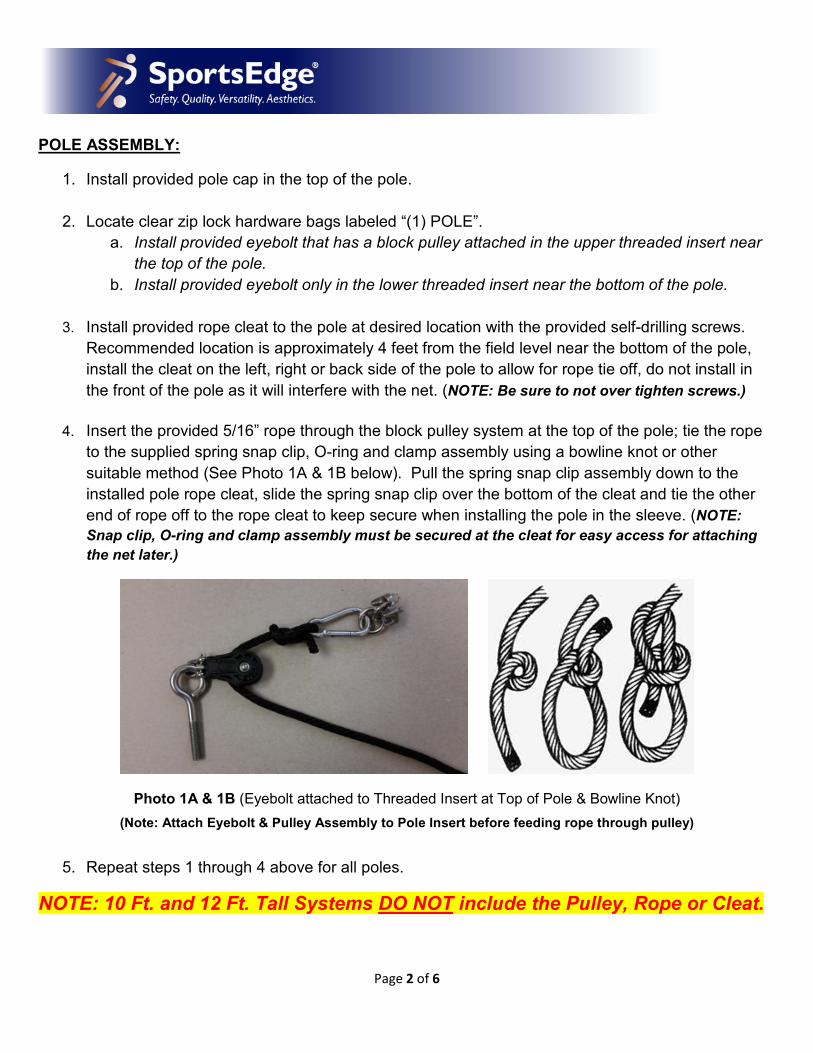
4. Insert the provided 5/16” rope through the block pulley system at the top of the pole; tie the rope
to the supplied spring snap clip, O-ring and clamp assembly using a bowline knot or other
suitable method (See Photo 1A & 1B below). Pull the spring snap clip assembly down to the
installed pole rope cleat, slide the spring snap clip over the bottom of the cleat and tie the other
end of rope off to the rope cleat to keep secure when installing the pole in the sleeve. (NOTE:
Snap clip, O-ring and clamp assembly must be secured at the cleat for easy access for attaching
the net later.)
Photo 1A & 1B (Eyebolt attached to Threaded Insert at Top of Pole & Bowline Knot)
(Note: Attach Eyebolt & Pulley Assembly to Pole Insert before feeding rope through pulley)
5. Repeat steps 1 through 4 above for all poles.
NOTE: 10 Ft. and 12 Ft. Tall Systems DO NOT include the Pulley, Rope or Cleat.
Page 3 of 6
END POLE ASSEMBLY:
After steps 1 through 4 listed above have been completed on all poles.
1. Locate clear zip lock hardware bags labeled “1 END POLE”. Each “End Pole” bag contains (1)
looped end cable, (2) cable/thimble packs, (2) turnbuckles and additional spring snap clips.
(NOTE: Items from “End Pole” hardware bag that are needed for this step: (1) Looped End
Cable, (1) Turnbuckle and (3) spring snap clips. Remaining spring snap clips, cable /
thimble packs and turnbuckle will be used in section “Attaching the Net” below.)
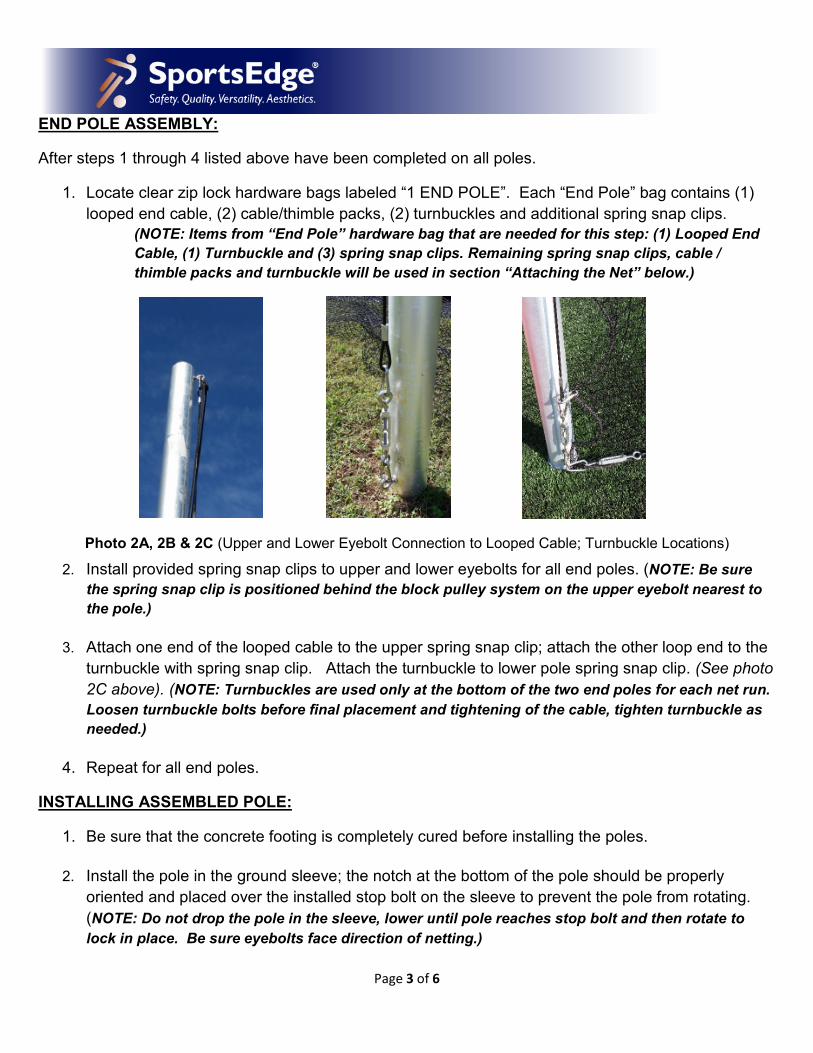
Photo 2A, 2B & 2C (Upper and Lower Eyebolt Connection to Looped Cable; Turnbuckle Locations)
2. Install provided spring snap clips to upper and lower eyebolts for all end poles. (NOTE: Be sure
the spring snap clip is positioned behind the block pulley system on the upper eyebolt nearest to
the pole.)
3. Attach one end of the looped cable to the upper spring snap clip; attach the other loop end to the
turnbuckle with spring snap clip. Attach the turnbuckle to lower pole spring snap clip. (See photo
2C above). (NOTE: Turnbuckles are used only at the bottom of the two end poles for each net run.
Loosen turnbuckle bolts before final placement and tightening of the cable, tighten turnbuckle as
needed.)
4. Repeat for all end poles.
INSTALLING ASSEMBLED POLE:
1. Be sure that the concrete footing is completely cured before installing the poles.
2. Install the pole in the ground sleeve; the notch at the bottom of the pole should be properly
oriented and placed over the installed stop bolt on the sleeve to prevent the pole from rotating.
(NOTE: Do not drop the pole in the sleeve, lower until pole reaches stop bolt and then rotate to
lock in place. Be sure eyebolts face direction of netting.)
Page 4 of 6
ATTACHING THE NET:
1. Lay nets flat on the ground on the field side of poles, be sure that net is pulled and stretched
completely out to full length. Position top section of the net closest to the poles, lower section of
the net farthest away from the poles.
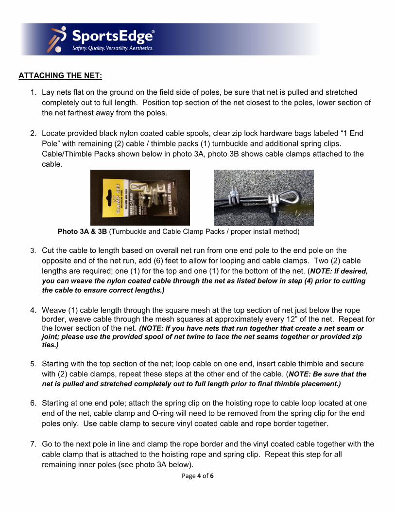
2. Locate provided black nylon coated cable spools, clear zip lock hardware bags labeled “1 End
Pole” with remaining (2) cable / thimble packs (1) turnbuckle and additional spring clips.
Cable/Thimble Packs shown below in photo 3A, photo 3B shows cable clamps attached to the
cable.
Photo 3A & 3B (Turnbuckle and Cable Clamp Packs / proper install method)
3. Cut the cable to length based on overall net run from one end pole to the end pole on the
opposite end of the net run, add (6) feet to allow for looping and cable clamps. Two (2) cable
lengths are required; one (1) for the top and one (1) for the bottom of the net. (NOTE: If desired,
you can weave the nylon coated cable through the net as listed below in step (4) prior to cutting
the cable to ensure correct lengths.)
4. Weave (1) cable length through the square mesh at the top section of net just below the rope border, weave cable through the mesh squares at approximately every 12” of the net. Repeat for the lower section of the net. (NOTE: If you have nets that run together that create a net seam or
joint; please use the provided spool of net twine to lace the net seams together or provided zip ties.)
5. Starting with the top section of the net; loop cable on one end, insert cable thimble and secure
with (2) cable clamps, repeat these steps at the other end of the cable. (NOTE: Be sure that the
net is pulled and stretched completely out to full length prior to final thimble placement.)
6. Starting at one end pole; attach the spring clip on the hoisting rope to cable loop located at one
end of the net, cable clamp and O-ring will need to be removed from the spring clip for the end
poles only. Use cable clamp to secure vinyl coated cable and rope border together.
7. Go to the next pole in line and clamp the rope border and the vinyl coated cable together with the
cable clamp that is attached to the hoisting rope and spring clip. Repeat this step for all
remaining inner poles (see photo 3A below).
Page 5 of 6
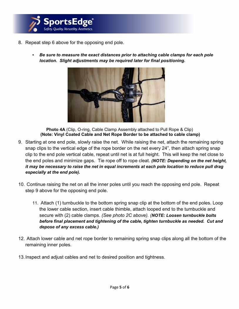
8. Repeat step 6 above for the opposing end pole.
• Be sure to measure the exact distances prior to attaching cable clamps for each pole
location. Slight adjustments may be required later for final positioning.
Photo 4A (Clip, O-ring, Cable Clamp Assembly attached to Pull Rope & Clip) (Note: Vinyl Coated Cable and Net Rope Border to be attached to cable clamp)
9. Starting at one end pole, slowly raise the net. While raising the net, attach the remaining spring
snap clips to the vertical edge of the rope border on the net every 24”, then attach spring snap
clip to the end pole vertical cable, repeat until net is at full height. This will keep the net close to
the end poles and minimize gaps. Tie rope off to rope cleat. (NOTE: Depending on the net height,
it may be necessary to raise the net in equal increments at each pole location to reduce pull drag
especially at the end pole).
10. Continue raising the net on all the inner poles until you reach the opposing end pole. Repeat
step 9 above for the opposing end pole.
11. Attach (1) turnbuckle to the bottom spring snap clip at the bottom of the end poles. Loop
the lower cable section, insert cable thimble, attach looped end to the turnbuckle and
secure with (2) cable clamps. (See photo 2C above). (NOTE: Loosen turnbuckle bolts
before final placement and tightening of the cable, tighten turnbuckle as needed. Cut and
depose of any excess cable.)
12. Attach lower cable and net rope border to remaining spring snap clips along all the bottom of the
remaining inner poles.
13. Inspect and adjust cables and net to desired position and tightness.
Page 6 of 6
MAINTENANCE and CARE:
1. Ball Stop Nets should always be lowered when not in use and especially in high wind, snow and ice storms.
2. To help prolong the life of the nets, the nets should be stored inside during the off season or if they will not be used for an extended period of time. Nets should be properly stored in a location that will avoid mice and pest damage.
__________________________________________________________________________
Component List for Each Pole
(1) Aluminum Pole
(1) Plastic Pole Cap (Black)
(1) Aluminum Ground Sleeve
(1) Plastic Ground Sleeve Cap (Black)
(1) 3/8” x 2.5” S.S. Eyebolt & (1) Block Pulley Assembly
(1) 3/8” x 2.5” S.S. Eyebolt
(2) 9/32” S.S. Spring Snap Clips
(1) ¾” S.S. O-ring & ¼” S.S. Cable Clamp
(1) 5/16” Black Poly Rope (Cut to length for specific pole height x 2 plus 5 feet)
(1) Aluminum Pole Cleat with (2) Self-drilling screws
NOTE: Block Pulley, 5/16” Rope and Pole Cleat are NOT provided with 10 Ft. & 12 Ft. Tall
Ball Stop Systems.
Net Hardware
(2) Lengths of the net run plus (6) feet of Black Vinyl Coated Cable (Cut on site)
(4) Cable Clamp / Thimble Packs
(2) 3/8” Turnbuckles
Additional Hardware list required for END POLES
(1) Pre-Cut Looped Black Vinyl Coated Cable Lengths (Sized for height of pole)
(1) 3/8” Turnbuckle
(3) 9/32” S.S. Spring Snap Clips
*Additional Spring Snap Clips (Quantity varies depending on the pole height; 1 extra clip provided
for every 2 feet of the pole)