Embed Size (px)
Citation preview

Band gap tunability of magneto-elastic phononic crystalO. Bou Matar, J. F. Robillard, J. O. Vasseur, A.-C. Hladky-Hennion, P. A. Deymier et al. Citation: J. Appl. Phys. 111, 054901 (2012); doi: 10.1063/1.3687928 View online: http://dx.doi.org/10.1063/1.3687928 View Table of Contents: http://jap.aip.org/resource/1/JAPIAU/v111/i5 Published by the American Institute of Physics. Related ArticlesPrediction of vibrational frequencies of possible intermediates and side products of the methanol synthesis onZnO(000) by ab initio calculations J. Chem. Phys. 136, 034706 (2012) Near-constant resistivity in 4.2-360 K in a B2 Al2.08CoCrFeNi AIP Advances 2, 012111 (2012) Negative refraction of elastic waves in 2D phononic crystals: Contribution of resonant transmissions to theconstruction of the image of a point source AIP Advances 1, 041405 (2011) Bloch wave deafness and modal conversion at a phononic crystal boundary AIP Advances 1, 041402 (2011) Diffraction of a focused x-ray beam from La3Ga5SiO14 crystal modulated by surface acoustic waves J. Appl. Phys. 110, 124902 (2011) Additional information on J. Appl. Phys.Journal Homepage: http://jap.aip.org/ Journal Information: http://jap.aip.org/about/about_the_journal Top downloads: http://jap.aip.org/features/most_downloaded Information for Authors: http://jap.aip.org/authors

Band gap tunability of magneto-elastic phononic crystal
O. Bou Matar,1,a) J. F. Robillard,2 J. O. Vasseur,2 A.-C. Hladky-Hennion,2 P. A. Deymier,3
P. Pernod,1 and V. Preobrazhensky4
1International Associated Laboratory LEMAC: IEMN, UMR CNRS 8520, PRES Lille Nord de France, ECLille,59652 Villeneuve d’Ascq, France2Institut d’Electronique, Microelectronique et Nanotechnologie (IEMN, UMR CNRS 8520),PRES Lille Nord de France, 59652 Villeneuve d’Ascq, France3Department of Materials Science and Engineering, University of Arizona, Tucson, Arizona 85721, USA4International Associated Laboratory LEMAC: Wave Research Center, GPI RAS, 38 Vavilov str., Moscow,119991, Russia
(Received 18 November 2011; accepted 28 January 2012; published online 1 March 2012)
The possibility of control and tuning of the band structures of phononic crystals offered by the
introduction of an active magnetoelastic material and the application of an external magnetic field is
studied. Two means to obtain large elastic properties variations in magnetoelastic material are
considered: Giant magnetostriction and spin reorientation transition effects. A plane wave expansion
method is used to calculate the band structures. The magnetoelastic coupling is taken into account
through the consideration of an equivalent piezomagnetic material model with elastic,
piezomagnetic, and magnetic permeability tensors varying as a function of the amplitude and
orientation of the applied magnetic field. Results of contactless tunability of the absolute bandgap
are presented for a two-dimensional phononic crystal constituted of Terfenol-D square rod embedded
in an epoxy matrix. VC 2012 American Institute of Physics. [http://dx.doi.org/10.1063/1.3687928]
I. INTRODUCTION
The concept of phononic crystals emerged in the early
1990s as an extension of work done on photonic crystal, i.e.,artificial structures whose dielectric permittivity and mag-
netic permeability are both periodic functions of the posi-
tion. Phononic crystals are the elastic counterparts to
photonic crystals and consist of periodic arrangements of
inclusions in a physically dissimilar matrix.1,2 Due to their
periodic structure and under certain conditions of geometry
and composition, phononic crystals may exhibit absolute
band gaps where the propagation of elastic wave is forbid-
den independently of the direction of propagation. The exis-
tence of forbidden bands confers to phononic crystals
numerous potential applications. For instance, in the fre-
quency range of the forbidden band, a phononic crystal
behaves as a perfect mirror and an incident wave is perfectly
reflected outside of the artificial structure. Phononic crystals
may be used as efficient sonic insulators. Some authors
have also shown that the removal of inclusions along some
pathway in the phononic crystal, produces acoustic
waveguides.3–6 Acoustic waves that would not propagate
otherwise in a phononic crystal can be guided with minimal
loss along such waveguides. Low loss transmission can be
achieved in linear wave guides as well as guides with sharp
bends. That opens possibilities for the design of devices
allowing the filtering or the demultiplexing of acoustic
waves at the scale of the wavelength.7,8 More specifically it
has been shown numerically and experimentally that such
structures manufactured at the micrometer scale behave as
high Q micromechanical resonators with high resonance
frequencies and can be integrated in devices for wireless
communications and sensing applications.9–12 Moreover
some dispersion curves in the band structure of a phononic
crystal may present a negative curvature, i.e., the Poynting
vector and the wave vector, associated to energy flux and
phase velocity are opposite in sign. This property may lead
to the negative refraction of acoustic waves for frequencies
falling in the frequency domain of the band with negative
curvature.13,14 Negative refraction allows for the focusing of
acoustic waves with a resolution lower than the diffraction
limit15,16 as well as for the autocollimation of an acoustic
beam.17,18
Phononic crystal may have applications to numerous
technological fields. Nevertheless, for enhanced functionality
it appears necessary to introduce a certain degree of fre-
quency tunability of phononic crystals properties. Different
answers to this problem have been proposed by several
authors. Tunability could be achieved by changing the geom-
etry of the inclusions19 or by varying the elastic characteris-
tics of the constitutive materials through application of
external stimuli.20 For instance, some authors have proposed
the use of electrorheological materials in conjunction with
application of external electric field.21 Other authors have
considered the effect of temperature on the elastic mod-
uli.22,23 In all cases, significant effect on the band structure
of the phononic crystal can only be achieved by applying
stimuli with very large magnitude. Other authors24 exploit
the change of the structure of the phononic crystal due to an
external stress to alter the band structure. However this
approach requires physical contact with the phononic crystal.
A last proposed solution requires using active materials as
constituents of the composite material. Following this way,
some authors25 have studied how the piezoelectric effect can
influence the elastic properties of the system and therefore
can change the dispersion curves and in particular the gaps.a)Electronic mail: [email protected].
0021-8979/2012/111(5)/054901/14/$30.00 VC 2012 American Institute of Physics111, 054901-1
JOURNAL OF APPLIED PHYSICS 111, 054901 (2012)
For an arrangement of piezoelectric cylinders embedded in a
polymer matrix, they show that the effect is significant for
large filling fractions but negligibly small for small ones.26
Several studies have reported noticeable changes in the band
structures of magnetoelectroelastic phononic crystals when
the coupling between magnetic, electric, and elastic phenom-
ena are taken into account.27,28 These studies however do
not consider the effect of an external magnetic field on the
properties of the phononic crystal. In a recent paper, we dem-
onstrated that the band structure of a two-dimensional pho-
nonic crystal constituted of a square array of Terfenol-D
square rods embedded in an epoxy resin matrix29 can be con-
trolled by application of an external magnetic field. Indeed,
the elastic properties of magnetoelastic material are very sen-
sitive to its magnetic state and on the applied magnetic field.
For instance, in giant magnetostrictive material, such as
Terfenol-D, this dependence can lead to more than 50% vari-
ation of some of the elastic constants, even at ultrasonic fre-
quencies.30 So, if one of the components of a phononic
crystal is a magneto-elastic medium, then one can expect
that the elastic contrast, and subsequently the crystal proper-
ties, e.g., the bang gaps frequencies and widths, the negative
refraction behaviors, could be controlled without any contact
by a magnetic field.
In the present paper, we give a complete derivation of
the model presented succinctly in our previous letter,29 and
use it to study in details the tuning of the properties of a
bulk magnetoelastic phononic crystal, with both square and
triangular lattices, when an external magnetic field is
applied. Moreover, we introduce here a new way to obtain
huge tuning of the band structures of a magneto-elastic pho-
nonic crystal. Indeed, contrary to previous works,29,31 we
consider two-dimensional magneto-elastic phononic crys-
tals in which the tuning can be induced not only by giant
magnetostriction, but also by spin-reorientation phase
transitions.32,33
To be able to consider arbitrary direction and amplitude
of the applied magnetic field, we will first derive an equiva-
lent piezomagnetic material of a polarized ferromagnet, with
field dependent elastic Cijkl, piezomagnetic qlij and magnetic
permeability lij constants. This is an extension of the effec-
tive elastic moduli method classically used to describe elastic
dynamics of a homogeneous magneto-elastic medium.32,34
But this latter method leads to a dependence of the obtained
effective elastic moduli on the propagation direction when
the magnetic dipole interaction is taken into account.35,36
This dependence makes these effective elastic moduli unsuit-
able for standard numerical tools developed for the calcula-
tion of phononic crystal characteristics (band structures,
equifrequency curves, transmission, and reflection coeffi-
cients …), such as plane wave expansion (PWE) or finite ele-
ment method (FEM), in the case of a magneto-elastic
phononic crystal. On the contrary, as will be shown in Sec.
II, the equivalent piezomagnetic material formulation, lead-
ing to equations similar to the ones classically used for pie-
zoelectric materials, enables the direct use of PWE and FEM
methods developed for the calculation of phononic crystal
characteristics in piezoelectric media.25,37,38 In Sec. III, cal-
culation of the effective piezomagnetic material properties
for a varying external magnetic field amplitude and direc-
tion, and its implication in the tuning of the band structure of
a phononic crystal constituted of a square array of Terfenol-
D square rods embedded in an epoxy matrix will be pre-
sented and discussed.
II. PIEZOMAGNETIC EQUIVALENT MATERIALFORMULATION
A. Formulation of the problem: Basic equations
We consider here a magneto-elastic wave in a ferromag-
net magnetized to saturation. In this case, the amplitude of
the magnetization per unit mass l is a constant ls. The
coupled equations for the mechanical and magnetic systems,
i.e., the equation of motion and the Landau-Lifshitz equa-
tion, have in the Lagrangian coordinates ai the form36,40,41
q0
@2ui
@t2¼ @Pij
@ajþ q0ln
@Hn
@aj
@aj
@xi; (1)
@l
@t¼ �cl0l�Heff ; (2)
where c is the gyromagnetic ratio, q0 is the mass density
before deformation, l0 is the permeability of vacuum, ui is
the ith component of the particle displacement, and xi
denotes the Eulerian coordinates. The magnetization per unit
volume is given by M¼ ql, where q is the mass density after
deformation. The magnetic-body force term, i.e., the second
term in the right hand side of Eq. (1), is due to the interaction
of the magnetization with non uniform magnetic fields. The
effective internal magnetic field Heff and the Piola-Kirchoff
stress tensor Pij are given by
Heff i ¼ Hi �1
l0q0
@U
@li
þ 1
l0q0
@
@as
@U
@ @li=@asð Þ (3)
and
Pij ¼@U
@gpj
@xi
@ap; (4)
where H is the Maxwellian magnetic field, and gkl is the
strain tensor
gij ¼1
2
@ui
@ajþ @uj
@aiþ @uk
@ai
@uk
@aj
� �: (5)
Here, U is the local internal energy per unit volume that can
be written in the following form:
U ¼ Uan þ Ume þ Ue; (6)
where the magnetocrystalline anisotropy, magneto-elastic
coupling, and elastic energies, are respectively, given by
Uan ¼ Kijaiaj þ Kijklaiajakal; (7)
Ume ¼ bijklaiajgkl; (8)
Ue ¼1
2Cijklgijgkl: (9)
054901-2 Bou Matar et al. J. Appl. Phys. 111, 054901 (2012)

ai¼li/ls are the direction cosines of l (or M) with respect
to the symmetry axes, Kij and Kijkl are the magnetic anisot-
ropy constants, bijkl are the magneto-elastic constants, and
Cijkl are the second-order elastic constants. Here, in the con-
sidered acoustic frequency range (up to a few GHz), the elas-
tic wavelengths are much greater than the atomic spacing so
that exchange effects may be neglected. In the case of a
cubic ferromagnet, such as the Terfenol-D considered in the
numerical example, the local internal energy density can be,
in the crystallographic axis, written as
U¼K1 a21a
22þ a2
1a23þ a2
2a23
� �þB1 g11a
21þ g22a
22þ g33a
23
� �þB2 g12a1a2þ g13a1a3þ g23a2a3ð Þ
þC11
2g2
11þ g222þ g2
33
� �þC12 g11g22þ g11g33þ g22g33ð Þ
þ 2C44 g212þ g2
13þ g223
� �; (10)
where K1¼K1111 is the magnetic anisotropy constant, and
B1¼ b1111 and B2¼ 4b1212 are the magneto-elastic constants.
As we are interested in acoustic wave propagation, we
consider only small dynamic perturbations around an equi-
librium state
H ¼ H0 þ h; M ¼ M0 þm; and u ¼ u0 þ ~u; (11)
H0 is the internal field, i.e., the sum of the external applied
field and a demagnetizing field, u0 is a spontaneous displace-
ment caused by magnetostriction, and h, m, and ~u are the
magnetostatic field, magnetization, and displacement gener-
ated by the magneto-elastic waves, respectively. Here, as the
wavelengths of the magneto-elastic waves are much smaller
than the free-space electromagnetic wavelengths, h verifies
the magnetostatic equations
r� h ¼ 0 and r � b ¼ r � l0 hþ qq0
m
� �¼ 0; (12)
where b is the dynamic magnetic induction and q� q0 (1� gii),
where i¼ 1, 2, or 3. Moreover, while this quasi-static
approximation is not strictly true for conducting materials,
one can expect it to hold when their dimensions are
much smaller than the skin depth. In the considered fre-
quency range, up to a few MHz, this will always be true
for all the studied phononic crystal structures.
As we are only interested by field dependent variations
of the elastic and piezomagnetic properties of the ferromag-
net, arising from the first order magnetoelastic coupling, i.e.,the “Simon effect”,42 we neglect all the field independent
morphic contributions coming from the magnetoelastic sec-
ond order coupling and anharmonic terms arising from the
second and third order elastic energies.41,43 Here, the contri-
butions introduced by the rotationally invariant theory of
magnetoelastic media33,44 are also neglected. Indeed, they
are negligible in the considered materials, as it will be shown
in Sec. IV. In the present paper, as it is always the case in the
literature, explicit expressions for the Simon effect are
derived assuming that a magnetic field sufficient for elimi-
nating the domain walls has been applied.
B. Equilibrium state
First, the equilibrium values M0 and u0 are found by
minimizing the total energy of the magneto-elastic system
UT¼U� l0M.H. We assume that the acoustic wave propa-
gation only induces small dynamic perturbations
m� M0; h� H0 and ~u� u0: (13)
Introducing Eq. (11) into Eq. (2), and allowing for conditions
(13), the successive approximations method can be used. In
the zero approximation, retaining only static terms, we obtain
M0 �Heff 0 ¼ 0: (14)
This expression indicates that the equilibrium direction of
magnetization M0 is given by the static effective internal
magnetic field Heff0.
To consider an external static magnetic field Hext in any
directions, we use the method of spherical coordinates
proposed by Smit and Beljers45 and Suhl46 for the study of
ferromagnetic resonance in anisotropic media. As the consid-
ered ferromagnet is magnetized to saturation, two variables,
h and u as shown on Fig. 1 are sufficient in place of the three
Mi components. In the spherical coordinates the components
of the total energy of the magneto-elastic system
UT¼UþUZþUD, where U is given by Eq. (6), are
UZ ¼ �l0M:Hext
¼ �l0MsðHx sin h cos uþ Hy sin h sin uþ Hz cos hÞ;(15)
UD ¼ �l0
2M:HD ¼
l0
2M:ðN:MÞ; (16)
Uan ¼K1
4ðsin4 h sin2 2uþ sin2 2hÞ; (17)
Ume ¼ B1ðg11 sin2 h cos2 uþ g22 sin2 h sin2 uþ g33 cos2 hÞþ B2ðg12 sin2 h cos usinuþg13 sin h cos h cos u
þ g23 sin h cos hsinuÞ: (18)
Here, Ms¼ q0ls, UZ and UD are the Zeeman and demag-
netizing energies, respectively, and HD¼�N.M, where N is
FIG. 1. (Color online) Schematic illustration showing the spherical coordi-
nates used in the calculation. oriented along the Z axis, the demagnetizing
tensor is given by Ref. 40.
054901-3 Bou Matar et al. J. Appl. Phys. 111, 054901 (2012)
the demagnetizing tensor. In the case of a rod of infinite length,
oriented along the Z axis, the demagnetizing tensor is given by
N ¼1=2 0 0
0 1=2 0
0 0 0
24
35; (19)
leading to UD¼ l0 M2s sin2h/4.
The first step, to find the equilibrium state, is to minimize
the energy UT with respect to the strains: @UT=@gij
¼ @ðUme þ UeÞ=@gij. The solutions of these six equations, in
the case of a crystal with cubic symmetry are given in Appen-
dix A. It can be seen that the existence of a magnetoelastic
coupling induces in the sample a uniform static strain. Intro-
ducing, now, these expressions of the equilibrium strains in
the elastic and magneto-elastic parts of the internal energy,
one can write the energy U in the same form as a magneto-
crystalline anisotropy energy47
U ¼ K�14ðsin4 h sin2 2uþ sin2 2hÞ; (20)
where
K�1 ¼ K1 þB2
1
C11 � C12
� B22
8C44
; (21)
K1* is an effective magnetic anisotropy constant taking into
account static elastic and magnetoelastic effects. Hence, as
the total energy of the magneto-elastic system depends only
on the orientation of the magnetization, minimizing the
energy with respect to this orientation gives the equilibrium
direction (h0, u0) of M, for a given applied field. Knowing
this equilibrium position, one can now study the dynamic
response of the system to an acoustic perturbation.
C. Piezomagnetic equivalent material
Here, we choose to derive the equivalent piezomagnetic
material of the polarized ferromagnet around the equilibrium
position. This will allow us to directly use the theoretical and
numerical tools, e.g., PWE and FEM methods, developed for
the study of piezoelectric or piezomagnetic phononic crystals.
A similar approach has been adopted by Ganguly et al.48,49
for the study of the influence of an external magnetic field on
the propagation of Rayleigh and Lamb waves in a thin magne-
toelastic film deposed on a substrate. But, in this work an
equivalent piezomagnetic material has been obtained only in
specific configurations.
First, the Landau-Lifshitz equations are rewritten in the
used spherical coordinates
@h@t¼ � c
Mssinh@U
@uþ cl0Hu ¼ cl0Hu
eff
@u@t¼ c
Mssinh@U
@h� c
sinhl0Hh ¼ � c
sinhl0Hh
eff ;
(22)
where Hu¼�HxsinuþHycosu, and Hh¼HxcoshcosuþHy
coshsinu�Hz sinh. The acoustic perturbation rotates the
magnetization to a new h and u orientation, where
h¼ h0þ dh and u¼u0þ du, with dh, du� 1. Then, the
energy is expended around the equilibrium position:
U ¼ U0 þ Uhdhþ Uuduþ Uhh=2dh2 þ Uuu=2du2
þ Uhudhduþ Uheijdh@ui=@aj þ Uueij
du@ui=@aj; (23)
where Ux and Uxy denote the first and second order x or x-yderivative of U, respectively.
In the frequency range of elastic wave, x�xS where
xS is the natural frequency of spin mode, the magnetic sub-
system has time to adjust itself to the elastic subsystem, lead-
ing to the following conditions @UT=@ðdhÞ ¼ 0 and
@UT=@ðduÞ ¼ 0. These conditions enable us to write dh and
du, as functions of ~u and h:
dh ¼ l0
DMsU
0uuhh � l0
DMssinh0huU0hu
þ 1
DU0huUueij � U0uuUheij
� � @~ui
@aj;
du ¼ �l0
DMsU
0huhh þ l0
DMssinh0huU0hh
þ 1
DU0huUheij � U0hhUueij
� � @~ui
@aj;
(24)
where D ¼ U0hhU0uu � Uhu02 and
U0hu¼Uhu�l0Mscosh0Hu0 ;
U0uu¼Uuuþl0Mssinh0 Hxcosu0þHysinu0
� �;
U0hh¼Uhhþl0Ms Hxsinh0cosu0þHysinh0sinu0þHzcosh0
� �:
(25)
Introducing these last expressions in the dynamic magnetiza-
tion, we obtain
mi ¼q0ikl
l0
@uk
@alþ vilhl; (26)
with the dynamic susceptibility tensor given by
v11 ¼l0M2
s
Dsin2h0sin2u0U0hh þ cos2h0cos2u0U0uu
�
þ 1
2sin2h0sin2u0U0hu
�;
v12 ¼l0M2
s
2D�sin2h0sin2u0U0hh þ cos2h0sin2u0U0uu
�
þsin2h0 sin2u0 � cos2u0
� �U0hu
�;
v13 ¼ �l0M2
s
D
1
2sin2h0cosu0U0uu þ sin2h0sinu0U0hu
� �;
v22 ¼l0M2
s
Dsin2h0cos2/0U0hh þ cos2h0sin2/0U0//
�
� 1
2sin2h0sin2/0U0h/
�;
v23 ¼l0M2
s
D� 1
2sin2h0sinu0U0uu þ sin2h0cosu0U0hu
� �;
v33 ¼l0M2
s
Dsin2h0U0uu; (27)
054901-4 Bou Matar et al. J. Appl. Phys. 111, 054901 (2012)

and
q0mij ¼ �bijkl
M2s
M0kvlm þM0lvkmð Þ: (28)
At this point, a second constitutive equation of the effective
piezomagnetic material needs to be found. Starting from the
definition of the Piola-Kirchoff stress tensor, i.e., Eq. (4),
and of the magnetic-body force, i.e., the second term of the
right hand side of Eq. (1), and, as before, using the method
of the successive approximations, retaining only the first
order dynamic terms, a dynamic stress component can be
defined as
rij ¼ Cijkl@uk
@alþ bijkl
M2s
M0kml þM0lmkð Þ þ l0M0ldijhl: (29)
Introducing in Eq. (29) the expressions (26) of the dynamic
magnetization, the dynamic stress tensor becomes
rij ¼ Cijkl þbijmn
l0M2s
M0nq0mkl þM0mq0nkl
� �� �@uk
@al
þ bijmn
M2s
M0nvml þM0mvnlð Þ þ l0M0ldij
� �hl: (30)
Noting that the factor in front of hl is nothing else than the
opposite of the piezomagnetic coefficients �qlij given by
qlij ¼ q0lij � l0M0ldij; (31)
we arrive at the piezomagnetic equations
q0
@2ui
@t2¼ @rij
@aj;
@bi
@ai¼ 0; (32)
with
rij ¼ Cijkl þ DCijkl
� � @uk
@al� qlijhl; (33)
bi ¼ qikl@uk
@alþ lilhl: (34)
Here, the effective magnetic permeability and elastic con-
stants are given by
lil ¼ l0 dil þ vilð Þ; (35)
CHijkl ¼ Cijkl þ DCijkl ¼ Cijkl þ
bijmn
l0M2s
M0nq0mkl þM0mq0nkl
� �:
(36)
For completeness, all the constants of the effective piezo-
magnetic material, in the considered case of a crystal with
cubic symmetry, are explicitly written as a function of h0
and u0 in Appendix B.
III. PIEZOMAGNETIC PHONONIC CRYSTAL
In the quasi-static approximation, a magnetic potential
um, from which the magnetic field derives, can be introduced
hl ¼ �@um=@al: (37)
Inserting this magnetic potential in Eqs. (33)–(34), the equiv-
alent piezomagnetic constitutive equations become
rij ¼ Cijkl þ DCijkl
� � @uk
@alþ qlij
@um
@al; (38)
bi ¼ qikl@uk
@al� lil
@um
@al: (39)
This formulation, similar to the one classically used for pie-
zoelectric materials, enables the direct used of the PWE
(Refs. 37 and 38) or FEM (Ref. 39) methods developed for
the calculation of phononic crystal characteristics in piezo-
electric media.
Let us first recall the basic principles of the PWE
method in this case. According to the Bloch-Floquet theo-
rem, the displacement vector and the magnetic potential can
be expanded in infinite Fourier series
ui r; tð Þ ¼X
G
uikþGej xt�k:r�G:rð Þ;
um r; tð Þ ¼X
G
ukþGej xt�k:r�G:rð Þ;(40)
where r¼ (x, y, z) is the vector position, x is the circular fre-
quency, G are the reciprocal lattice vectors, and k is the
wave vector. Moreover, due to the periodicity the material
constants q(r), Cijkl(r), qlij(r), and lij(r) are also expanded as
Fourier series
a rð Þ ¼X
G
aGe�jG:r: (41)
Inserting these expansions, Eqs. (40)–(41), in Eqs. (32) and
(38)–(39), using orthogonality property of Fourier series
components and collecting terms, yields the following gener-
alized eigenvalue equation37
x2 ~R ~U ¼ Ci~AilCl
~U; (42)
where ~U is a vector gathering the Fourier amplitudes of the
generalized displacement u¼ (u1, u2, u3, um), ~R, ~Ail are
4N� 4N matrix involving only material constants, and Ci are
diagonal matrices involving the wave vector and the Bloch
wave vector. The detailed expressions of all these matrices
are given in Appendix C. By solving Eq. (42) for x as a
function of the wave vector k in the first Brillouin zone of
the considered lattice, the band structures can be calculated.
This system of Eq. (42) can also be rewritten as a function of
x and the wave vector direction, leading to a generalized
eigenvalue problem for the wave vector k. In this case, this
formulation can be used to build the complex band structure
of the phononic crystal.50,51
IV. RESULTS AND DISCUSSION
A. Piezomagnetic equivalent material
In order to compare our results to the ones previously
obtained in the literature, we consider piezoelectrically
054901-5 Bou Matar et al. J. Appl. Phys. 111, 054901 (2012)
stiffened elastic constants, as frequently used in piezoelectric
materials:52
�Cijkl ¼ CHijkl þ
qpijnpnqqqkl
lmnnmnn; (43)
where ni are the components of the unit vector in the direc-
tion of wave propagation. These stiffened elastic constants,
as expressed, depend on the propagation direction, and so
cannot be directly used in numerical scheme.
First of all, to validate the obtained results, we consider
the case of the influence of an external magnetic field on the
propagation of a longitudinal wave along the length of a cubic
magnetoelastic rod studied by Eastman.41 The rod is oriented
along the Z axis, and K1¼ 0 and BiE0i � 0 (see Appendix A).
The corresponding stiffened elastic constant �C33, calculated
from Eq. (43) with n1¼ n2¼ 0 and n3¼ 1, is given by
�C33 ¼ CH33 þ
q233
l33
¼ C33 þ DC33 þq2
33
l33
; (44)
where from Eqs. (31), (35), and (36) the piezomagnetic, per-
meability, and elastic constants are
q33 ¼ �2B1
H0
cosh0sin2h0 � l0Mscosh0; (45)
l33 ¼l0
H0
H0 þMssin2h0
� �; (46)
DC33 ¼ �4B2
1
l0MsH0
cos2h0sin2h0: (47)
H0¼HextþHD is the internal magnetic field. Introducing
Eqs. (45)–(47) in Eq. (44) we obtain
�C33 ¼ C33 �2B1 � l0M2
s
� �2cos2h0sin2h0
l0 MsH0 þM2s sin2h0
� � : (48)
It corresponds to the classical observation that the sound ve-
locity is always reduced when magnetoelastic effects are pres-
ent, leading to an apparent softening of the relevant elastic
coefficient. The velocity of the corresponding longitudinal
wave is then calculated by cl ¼ffiffiffiffiffiffiffiffiffiffiffiffiffiffi�C33=q0
p. This expression
corresponds to the magnetic field dependent part given in
Table II of Ref. 41. As already pointed out by Eastman,41 the
magnetic body force affects only longitudinal modes and
results in Bi appearing in the form Bi � l0M2s
� �2for longitu-
dinal wave velocities in place of B2i for shear wave velocities.
Now, we consider the case of a cubic magnetoelastic rod,
as the one that will be used in the phononic crystal (Fig. 1),
with an applied external magnetic field along one of the crys-
tallographic axis. When the magnetic field is applied along Z,
parallel to the rod length, the only non zero permeabilities,
piezomagnetic constants, and elastic constant variations are
l11 ¼ l22 ¼ l0 1þ Ms
H0 þ Han þ Hme
� �; l33 ¼ l0; (49)
q24 ¼ q15 ¼ �B2=2
H0 þ Han þ Hme; (50)
DC44 ¼ DC55 ¼ �B2
2=4
l0Ms H0 þ Han þ Hmeð Þ ; (51)
where Han ¼ 2K�1
l0Msis the anisotropic field, and Hme ¼ B2
2
4C44l0Ms
is the magnetoelastic field. If the magnetic field is applied
along X or Y, the non zero constants of the effective piezo-
magnetic material are given by Eqs. (49)–(51), simply apply-
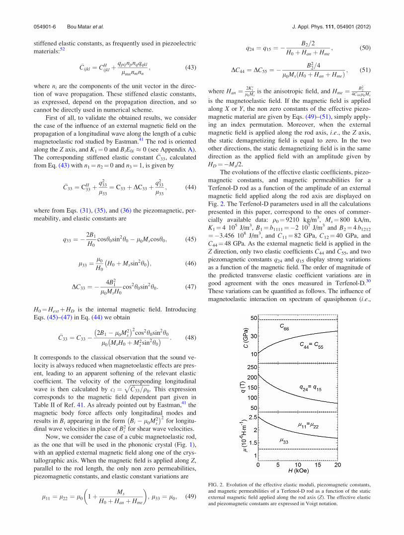
ing an index permutation. Moreover, when the external
magnetic field is applied along the rod axis, i.e., the Z axis,
the static demagnetizing field is equal to zero. In the two
other directions, the static demagnetizing field is in the same
direction as the applied field with an amplitude given by
HD¼�Ms/2.
The evolutions of the effective elastic coefficients, piezo-
magnetic constants, and magnetic permeabilities for a
Terfenol-D rod as a function of the amplitude of an external
magnetic field applied along the rod axis are displayed on
Fig. 2. The Terfenol-D parameters used in all the calculations
presented in this paper, correspond to the ones of commer-
cially available data: q0¼ 9210 kg/m3, Ms¼ 800 kA/m,
K1¼ 4 105 J/m3, B1¼ b1111¼�2 107 J/m3 and B2¼ 4 b1212
¼�3.456 108 J/m3, and C11¼ 82 GPa, C12¼ 40 GPa, and
C44¼ 48 GPa. As the external magnetic field is applied in the
Z direction, only two elastic coefficients C44 and C55, and two
piezomagnetic constants q24 and q15 display strong variations
as a function of the magnetic field. The order of magnitude of
the predicted transverse elastic coefficient variations are in
good agreement with the ones measured in Terfenol-D.30
These variations can be quantified as follows. The influence of
magnetoelastic interaction on spectrum of quasiphonon (i.e.,
FIG. 2. Evolution of the effective elastic moduli, piezomagnetic constants,
and magnetic permeabilities of a Terfenol-D rod as a function of the static
external magnetic field applied along the rod axis (Z). The effective elastic
and piezomagnetic constants are expressed in Voigt notation.
054901-6 Bou Matar et al. J. Appl. Phys. 111, 054901 (2012)

hybrid magneto-elastic waves), generally small, is character-
ized by the following dimensionless coupling parameter:32
f ¼ xme
x0
; (52)
where x0 ¼ c H0 þ Han þ Hmeð Þ is the magnon frequency and
xme ¼ cHme is the magnetoelastic coupling contribution to
the magnon frequency. In a giant magnetostrictive material,
for example, in the Terfenol-D rod sample considered here,
Hme¼ 7.5 kOe, Han¼ 2.5 kOe, and for H0¼ 10 kOe, we
obtain f¼ 0.375 indicating a high magnetoelastic coupling.
The variations of the diagonal terms of the effective
magnetic permeability tensor are also displayed in Fig. 2.
In the considered case of an external magnetic field
applied along the Z axis, the only field dependent stiffened
elastic constants are
�C44 ¼ CH44 þ
q224n2
2
l11n21 þ l22n2
2 þ l0n23
; (53)
�C55 ¼ CH55 þ
q224n2
1
l11n21 þ l22n2
2 þ l0n23
; (54)
�C45 ¼q2
24n1n2
l11n21 þ l22n2
2 þ l0n23
; (55)
where n¼ (n1, n2, n3) is a unit vector in the propagation
direction. To calculate the velocities of the three propagating
waves, in a given direction, the following characteristic
equation needs to be solved:52
det Cil � q0V2� �
¼ 0; (56)
where Cil ¼ �Cijklnjnk is the Christoffel tensor. Considering
elastic waves propagating in the XY plane, i.e., n1¼ cos U,
n2¼ sin U and n3¼ 0 where U is the angle between the prop-
agation direction and the X axis, the characteristics equation
becomes
C33 � q0V2� �
C11 � q0V2� �
C22 � q0V2� �
� C212
� �¼ 0;
(57)
where
C11 ¼ C11cos2Uþ C44sin2U;
C22 ¼ C44cos2Uþ C11sin2U;
C33 ¼ �C55cos2Uþ �C44sin2Uþ 2 �C45cosUsinU
¼ C44 �B2
2=4
l0Ms Ms þ H0 þ Han þ Hmeð Þ :
(58)
Here only the component C33 of the Christoffel tensor is field
dependent. So, only the decoupled out of plane transverse
mode, with velocityffiffiffiffiffiffiffiffiffiffiffiffiffiffiC33=q0
p, depends on the external
magnetic field. The slowness polar diagrams calculated for
elastic waves propagating in the XY plane, using the effective
piezomagnetic material properties are shown in Fig. 3 for
three increasing values of the amplitude of the external mag-
netic field: 1 kOe (dashed line), 10 kOe (dotted line), and
20 kOe (solid line). In this configuration, only the out of
plane transverse wave, propagating with the velocity and
with displacement directed along the applied static magnetic
field, is coupled to this magnetic field.
Considering now a magnetic field applied in a direction
perpendicular to the Terfenol-D rod, the evolution of the
parameters of the effective piezomagnetic material as a
function of the amplitude of the external magnetic field are
presented in Fig. 4. In this configuration, elastic waves
FIG. 3. Slowness polar diagram for propagation in a Terfenol-D rod with a
static external magnetic field, applied along the rod axis (Z), of 1 kOe
(dashed line), 10 kOe (dotted line), and 20 kOe (solid line).
FIG. 4. Evolution of the effective elastic moduli, piezomagnetic constants,
and magnetic permeabilities of a Terfenol-D rod as a function of the static
external magnetic field applied along the X axis. The effective elastic and
piezomagnetic constants are expressed in Voigt notation.
054901-7 Bou Matar et al. J. Appl. Phys. 111, 054901 (2012)

propagating in the XY plane are described by the same char-
acteristics equation, i.e., Eq. (57), with now
C11 ¼ C11cos2Uþ �C66sin2U;
C22 ¼ �C66cos2Uþ C11sin2U;
C33 ¼ �C55cos2Uþ C44sin2U;
C12 ¼ C12 þ �C66ð Þ cosUsinU;
(59)
and
�C55 ¼ C55 �B2
2=4
l0Ms H0 þ Han þ Hmeð Þ ; (60)
�C66 ¼ C55 �B2
2=4
l0Ms H0 þ Han þ Hme þMssin2U� � : (61)
Contrary to the previous case, all the Christoffel tensor
components are now field dependent. As shown on Fig. 5,
displaying the slowness polar diagrams for an external field
of 4 kOe (dashed line), 10 kOe (dotted line), and 20 kOe
(solid line), this leads to the fact that all the modes are now
affected by the magnetic field, even if the influence on the
quasi-longitudinal mode is still low.
Moreover, the induced velocities variations of the trans-
verse waves, both in plane and out of plane, become very
large for propagation in the X direction, due to the presence
of a magnetic spin reorientation transition (SRT). It is well
known that the magnetoelastic coupling can become signifi-
cant near a SRT if the magnetic mode of frequency x0 that
interacts with the sound is a soft mode, i.e., a mode with
x0¼xme at the SRT, leading to f¼ 1 at the transition. Start-
ing from a high amplitude, around 20 k0e, external magnetic
field oriented along the X axis, and then decreasing its ampli-
tude, the ground state M0//Hext//X is stable under the
condition:32
2K�1l0Ms
þ H0 ¼ Han þ H0 0; (62)
where K�1 is given by Eq. (21). At the SRT, i.e., when
Han þ H0 ¼ 0 or Hext ¼ �Han � HD, the equilibrium state
suddenly changes, as shown on Fig. 6. Note that u0¼ 0 for
all values of the external applied field. For the considered
Terfenol-D sample, the SRT corresponds to Hext¼ 2.56 kOe.
Close to the SRT, e.g.. for Hext¼ 4 kOe, for a propagation
along the external magnetic field direction (U ¼ 0), the
phase velocity of the transverse waves, ct ¼ffiffiffiffiffiffiffiffiffiffiffiffiffiffi�C55=q0
p, tends
to zero. In the other hand, when the propagation is perpen-
dicular to the external field direction, only the in plane trans-
verse wave velocity shows a slight variation as a function of
the magnetic field amplitude. The difference between these
two cases arises from the existence of a dynamic dipole field
h ¼ Mssin2U created by the magnetoelastic waves propaga-
tion. As shown in Eq. (61), when k // M0 // X the dynamic
dipole field h becomes zero. But with increasing angle
between k and M0, the dipole field increases up to Ms when
k becomes perpendicular to M0. This field is added to the
static demagnetizing field leading to
f ¼ Hme
H0 þMs þ Han þ Hmeð Þ ; (63)
and the magnetoelastic coupling parameter decreases even at
SRT where fSRT � 0.43 for Terfenol-D. So the long-range
dipole interaction can considerably weaken the magnetoelas-
tic coupling at the SRT for waves propagating in an arbitrary
direction.
To conclude this part, we consider the results obtained
in the rotationally invariant theory,32 when the external mag-
netic field is applied along the Z axis. The term B2 in the field
dependent variations of the stiffened elastic constant �C44 is
replaced by B2 6 K1me where
K1me ¼ K1 �B1B2
4 C11 � C12ð Þ:
FIG. 5. Slowness polar diagram for propagation in a Terfenol-D rod with a
static external magnetic field, applied along the X axis, of 4 kOe (dashed
line), 10 kOe (dotted line), and 20 kOe (solid line).
FIG. 6. (Color online) Evolution of the equilibrium state (h0, u0) for an
external static magnetic field of decreasing amplitude applied along the X
axis: h0 solid line and u0 dashed line. A spin reorientation transition (SRT)
appears at Hext¼ 2.56 kOe.
054901-8 Bou Matar et al. J. Appl. Phys. 111, 054901 (2012)

The 6 sign depends on the wave propagation direction
k:þ if k ?M0 and - if k // M0. In the considered case of
Terfenol-D rod, K1me � 3.59� 105 J/m3 is negligible in com-
parison with B2 � 3.456� 108 J/m3. This last point justifies
our choice to neglect the effects introduced by the considera-
tion of the complete rotationally invariant theory.
B. Piezomagnetic phononic crystal
We study now the influence of the introduction of a mag-
netoelastic medium on the properties of phononic crystals.
The calculations have been made for square and triangular lat-
tices of Terfenol-D square rods of section d¼ 1 mm embed-
ded in an epoxy matrix. The matrix is constituted of epoxy
resin, considered as isotropic and with the following parame-
ters: q0¼ 1142 kg/m3, C11¼ 7.54 GPa, and C44¼ 1.48 GPa.
441 plane waves have been used in the PWE calculation of
the band structure. Comparison with FEM results has con-
firmed the convergence of the Fourier series.
The demagnetizing field depends only on the magnetiza-
tion and the geometrical shape of the sample. Up to now, the
demagnetizing contribution, as described by Eqs. (16) and
(19), has been calculated for an isolated rod of infinite
length. At this point, it becomes important to estimate the
influence of the magnetostatic fields of the surrounding mag-
netoelastic rods on the demagnetizing field, when the pho-
nonic crystal is constructed. In fact, it has been demonstrated
by Ignatchenko et al.53 that the average magnetostatic field
inside a rod in a periodic arrangement of infinitely long
square rods is
hHDi ¼�Ms
21� fð Þ; (64)
where f is the filling factor. This equation is also valid for a
periodic array of magnetoelastic rods embedded in a non
magnetic matrix. So the demagnetizing field is decreased by
a factor (1� f) in the phononic crystal configuration in com-
parison to an isolated rod. This shifts the value of the exter-
nal magnetic field corresponding to the SRT by a factor of
�f Ms/2. Moreover, it can be shown that even in the real case
where the rods have a finite length h, Eq. (64) remains a very
good approximation as soon as h/a � 1.5, where a is the lat-
tice period.54 When M0 // Z, where Z is along the rod length,
the neighboring square rods have no influence, and the
demagnetizing field remains equal to zero.
1. Square lattice phononic crystals
We study the evolution of the band structure of square
lattice phononic crystals, as a function of the amplitude and
the orientation of the external magnetic field, induced by the
variations of the effective parameters of the Terfenol-D rods
shown in Figs. 2–5. The band structures displayed in Fig. 7
give a typical example of the magnetic field influence when
applied along the rod axis. With a filling factor f¼ (d/a)2
¼ 0.35 and an applied field Hext¼ 3 kOe, the phononic crystal
possesses an absolute bandgap in the 0–1 MHz frequency
FIG. 7. (Color online) Band structure of a square lattice of Terfenol-D
square rods with a filling factor f¼ (d/a)2¼ 0.35, embedded in an epoxy ma-
trix for two applied static magnetic fields along the rod axis Z: (a) Hext¼ 3
kOe and (b) Hext¼ 10 kOe.
FIG. 8. Evolution of the absolute elastic band gaps of a square lattice of
Terfenol D square rods embedded in an epoxy matrix as a function of the
amplitude of the applied static external magnetic field along the rod axis Z,
for a filling factor (a) f¼ 0.35 and (b) f¼ 0.5.
054901-9 Bou Matar et al. J. Appl. Phys. 111, 054901 (2012)

range, as shown in Fig. 7(a). When the external field is
increased to 10 kOe, a second absolute bandgap, ranging from
approximately 0.76 to 0.8 MHz, appears (Fig. 7(b)). More-
over, the frequency range of the first absolute band gap is
slightly increased. More precisely, the application of a mag-
netic field with an amplitude higher than 6 kOe increases the
bandwidth of the bandgap, and opens a second one in the 0-1
MHz frequency range, as shown in Fig. 8(a). So, elastic waves
are evanescent waves in this phononic crystal at 0.8 MHz
when the field becomes higher than 6 kOe. When the filling
factor is increased to 0.5, as shown in Fig. 8(b), the process is
inverted: The second absolute band gap disappears when the
amplitude of the external magnetic field is increased. In both
cases, the phononic crystal behaves as a switch controlled
without any contact by an external applied magnetic field.
Nevertheless, in this case, where the magnetic field is applied
along the rod axis, the band gap width variation remains lower
than 25%. Moreover, a careful look at the band structures of
Fig. 7 has shown that only modes polarized along Z are
coupled to the external field.29
FIG. 10. (Color online) Band structure of a square lattice of Terfenol-D square rods with a filling factor f¼ (d/a)2¼ 0.35, embedded in an epoxy matrix for an
applied static magnetic field Hext¼ 10 kOe (a) along the rod axis Z and (b) along the X axis, perpendicular to the rod axis. The inset shows the irreducible Bril-
louin zone of the square array. The dashed ellipses highlight the strong anisotropy induced by the external static magnetic field.
FIG. 9. Evolution of the absolute elastic band gaps of a square lattice of
Terfenol-D square rods with a filling factor f¼ 0.5, embedded in an epoxy
matrix, as a function of the amplitude of the applied static external magnetic
field along the X axis perpendicular to the rod axis.
FIG. 11. Band structure of a triangular lattice of Terfenol-D square rods
with a filling factor f¼ (d/a)2¼ 0.35, embedded in an epoxy matrix for two
applied static magnetic fields along the rod axis Z: (a) Hext¼ 3 kOe and (b)
Hext¼ 10 kOe.
054901-10 Bou Matar et al. J. Appl. Phys. 111, 054901 (2012)

When the magnetic field is applied perpendicularly to
the Terfenol-D rod axis, the absolute band gap evolution dis-
played in Fig. 9 shows more important variations than in the
previous considered case where the magnetic field was along
the rod axis. This can be directly linked to the SRT described
in the preceding section. The calculations have been made
for decreasing external magnetic field amplitude down to
4 kOe, not too close to the SRT. Indeed, below and close to
the SRT, the used assumption of uniformerly oriented mag-
netization becomes doubtful.
In the previous examples, the band structure modifica-
tions were obtained by varying the amplitude of the applied
magnetic field. Another way to induce such modifications is
by changing the field direction, keeping the amplitude con-
stant. As shown in Fig. 10, the band structure of a square
lattice of Terfenol-D square rods embedded in an epoxy
matrix with a filling factor f¼ 0.35 can become strongly
anisotropic only by switching the direction of the applied
field from the Z axis to the X axis, as highlighted by the
dashed ellipses. Indeed, it has been demonstrated in Sec. IV
A that close to the SRT the elastic behavior of the magne-
toelastic medium becomes highly anisotropic, due to the
dynamic dipole field.
2. Triangular lattice phononic crystals
We study now the evolution of the band structure of tri-
angular lattice phononic crystals, along the contours of the
first irreducible Brillouin zone, as a function of the amplitude
of an external magnetic field applied along the rod axis. As
for square lattice case, the band structure of a triangular lat-
tice of Terfenol-D square rods, with a filling factor of 0.35,
embedded in an epoxy matrix is considerably modified when
the amplitude Hext is changed from 3 kOe to 10 kOe, as
shown in Fig. 11. Here, in the 0 to 1 MHz frequency range,
only one absolute bandgap appears, and its width increases
with the external magnetic field amplitude. Comparatively to
the square lattice case, this band gap width increase is larger,
here, for a triangular lattice.
Figure 12 displays the evolution of the absolute band
gaps, for the same triangular lattice magnetoelastic phononic
crystal, as a function of the amplitude of the applied external
field along the rod axis for two filling factor 0.35 (a) and 0.5
(b). Here, for both filling factors the second absolute band
gap disappears when the amplitude of the external magnetic
field is increased, even if the closing amplitude is consider-
ably higher, 16 kOe in place of 3 kOe, when f¼ 0.5. More-
over, the increase of the width of the first absolute band gap
with the external magnetic field amplitude is largely higher
for triangular lattices than for square ones. For example,
when f¼ 0.5 the width of the first gap, ranging from approxi-
mately 0.52 to 0.59 MHz when Hext¼ 1 kOe, is multiplied
by a factor of 5 when the magnetic field is increased up to 20
kOe (where the gap ranges from 0.52 to 0.89 MHz). These
variations are in the same order of magnitude as the ones
obtained in the case of the square lattice magnetoelastic pho-
nonic crystal, considered in the previous paragraph, when we
are close to a SRT.
V. CONCLUSION
We have demonstrated the feasibility of tuning the band
structure of a magnetoelastic phononic crystal constituted of
rods of magnetoelastic material embedded in an epoxy matrix
by applying an external magnetic field. Indeed, the elastic
properties of magneto-elastic material are very sensitive to its
magnetic state and on the applied magnetic field. For instance,
in giant magnetostrictive material, such as Terfenol-D, we
have shown that this dependence can lead to more than 50%
variation of some of the elastic constants. Moreover, the use
of giant magnetostriction is not the only means to obtain large
elastic properties variations in magnetic materials, and we
have also considered spin-reorientation phase transitions
effects. In both cases, band structures have been calculated
with a plane wave expansion method that accounts for cou-
pling between the elastic behavior and the magnetic field
through the development of an equivalent piezomagnetic ma-
terial of a polarized ferromagnet, with elastic, piezomagnetic,
and magnetic permeability effective tensors. The introduction
of a magnetoelastic constituent opens the possibility of easy
controllability of the properties of a phononic crystal without
any contact. More specifically one can achieve additional
functionalities such as the switching of transmission in a
defined frequency range.
FIG. 12. Evolution of the absolute elastic band gaps of a triangular lattice of
Terfenol D square rods embedded in an epoxy matrix as a function of the
amplitude of the applied static external magnetic field along the rod axis Z,
for a filling factor (a) f¼ 0.35 and (b) f¼ 0.5.
054901-11 Bou Matar et al. J. Appl. Phys. 111, 054901 (2012)

APPENDIX A: EQUILIBRIUM STRAINS
The equilibrium strains E0ij, obtained by minimization of
the energy UT, can be shown to be47
E011 ¼ �h1a
021 þ C ¼ �h1sin2h0cos2u0 þ C; (A1)
E022 ¼ �h1a
022 þ C ¼ �h1sin2h0sin2u0 þ C; (A2)
E033 ¼ �h1a
023 þ C ¼ �h1cos2h0 þ C; (A3)
E023 ¼ �h2a
02a
03 ¼ �
h2
2sin2h0sinu0; (A4)
E013 ¼ �h2a
01a
03 ¼ �
h2
2sin2h0cosu0; (A5)
E012 ¼ �h2a
01a
02 ¼ �
h2
2sin2h0sin2u0; (A6)
where
h1 ¼B1
C11 � C12
; (A7)
h2 ¼B2
4C44
; (A8)
and
C ¼ B1C12
C11 � C12ð Þ C11 þ 2C12ð Þ : (A9)
APPENDIX B: EFFECTIVE CONSTANTS
The effective magnetic permeability lij, piezomagnetic
coupling coefficient qiJ, and elastic constant correction DCI J
for a cubic system are given in Voigt notation (where i,j¼ 1, 2, 3 and I, J¼ 1, 2, … 6) by:
l11 ¼ l0ð1þ v11Þ
l12 ¼ l0v12
l13 ¼ l0v13
l22 ¼ l0ð1þ v22Þ
l23 ¼ l0v23
l33 ¼ l0ð1þ v33Þ
q11 ¼ �2B1
Mssinh0cosu0v11 � l0Mssinh0cosu0
q12 ¼ �2B1
Mssinh0sinu0v12 � l0Mssinh0cosu0
q13 ¼ �2B1
Mscosh0v13 � l0Mssinh0cosu0
q14 ¼ �B2
2Msðsinh0sinu0v13 þ cosh0v12Þ
q15 ¼ �B2
2Msðsinh0cosu0v13 þ cosh0v11Þ
q16 ¼ �B2
2Msðsinh0cosu0v12 þ sinh0sinu0v11Þ;
q21 ¼ �2B1
Mssinh0cosu0v12 � l0Mssinh0sinu0;
q22 ¼ �2B1
Mssinh0sinu0v22 � l0Mssinh0sinu0;
q23 ¼ �2B1
Mscosh0v23 � l0Mssinh0sinu0;
q24 ¼ �B2
2Msðsinh0sinu0v23 þ cosh0v22Þ;
q25 ¼ �B2
2Msðsinh0cosu0v23 þ cosh0v12Þ;
q26 ¼ �B2
2Msðsinh0cosu0v22 þ sinh0sinu0v12Þ;
q31 ¼ �2B1
Mssinh0cosu0v13 � l0Mscosh0;
q32 ¼ �2B1
Mssinh0sinu0v23 � l0Mscosh0;
q33 ¼ �2B1
Mscosh0v33 � l0Mscosh0;
q34 ¼ �B2
2Msðsinh0sinu0v33 þ cosh0v23Þ;
q35 ¼ �B2
2Msðsinh0cosu0v33 þ cosh0v13Þ;
q36 ¼ �B2
2Msðsinh0cosu0v23 þ sinh0sinu0v13Þ;
DC11 ¼ �4B2
1
M2s
sin2h0cos2u0v11;
DC12 ¼ �4B2
1
M2s
sin2h0cosu0sinu0v12;
DC13 ¼ �4B2
1
M2s
cosh0sinh0cosu0v13;
DC14 ¼ �B1B2
M2s
sinh0cosu0ðsinh0sinu0v13 þ cosh0v12Þ;
DC15 ¼ �B1B2
M2s
sinh0cosu0ðsinh0cosu0v13 þ cosh0v11Þ;
DC16 ¼ �B1B2
M2s
sinh0cosu0ðsinh0cosu0v12 þ sinh0sinu0v11Þ;
054901-12 Bou Matar et al. J. Appl. Phys. 111, 054901 (2012)

DC22 ¼ �4B2
1
M2s
sin2h0sin2u0v22;
DC23 ¼ �4B2
1
M2s
sinh0cosh0sinu0v23;
DC24 ¼ �B1B2
M2s
sinh0sinu0ðsinh0sinu0v23 þ cosh0v22Þ;
DC25 ¼ �B1B2
M2s
sinh0sinu0ðsinh0cosu0v23 þ cosh0v12Þ;
DC26 ¼ �B1B2
M2s
sinh0sinu0ðsinh0cosu0v22 þ sinh0sinu0v12Þ;
DC33 ¼ �4B2
1
M2s
cosh20v33;
DC34 ¼ �B1B2
M2s
cosh0ðsinh0sinu0v33 þ cosh0v23Þ;
DC35 ¼ �B1B2
M2s
cosh0ðsinh0cosu0v33 þ cosh0v13Þ;
DC36 ¼ �B1B2
M2s
cosh0ðsinh0cosu0v23 þ sinh0sinu0v13Þ;
DC44 ¼ �B2
2
4M2s
ðsin2h0sin2u0v33 þ cos2h0v22
þ 2cosh0sinh0sinu0v23Þ;
DC45 ¼ �B2
2
4M2s
ðsin2h0cosu0sinu0v33 þ cos2h0v12
þ cosh0sinh0cosu0v23 þ cosh0sinh0sinu0v13Þ;
DC46 ¼ �B2
2
4M2s
ðsin2h0cosu0sinu0v23 þ sin2h0sin2u0v13
þ cosh0sinh0cosu0v22 þ cosh0sinh0sinu0v12Þ;
DC55 ¼ �B2
2
4M2s
ðsin2h0cos2u0v33 þ cos2h0v11
þ 2cosh0sinh0cosu0v13Þ;
DC56 ¼ �B2
2
4M2s
ðsin2h0cosu0sinu0v13 þ sin2h0cos2u0v23
þ cosh0sinh0cosu0v12 þ cosh0sinh0sinu0v11Þ;
DC66 ¼ �B2
2
4M2s
ðsin2h0cos2u0v22 þ sin2h0cos2u0v11
þ 2sin2h0sinu0cosu0v12Þ;
where the components of the susceptibility tensor vij are
given by Eqs. (27) with
U0hh¼l0Ms Hxsinh0cosu0þHysinh0sinu0þHzcosh0
� �þK1 2cos4h0þ3sin22u0cos2h0sin2h0�sin22u0sin4h0
� �þ2B1 E0
11cos2h0cos2u0þE022cos2h0sin2u0
��E0
33cos2h0
�þB2 E0
12cos2h0sin2u0�2E023sin2h0sinu0
��2E0
13sin2h0cosu0
�; (B1)
U0uu ¼l0Ms Hxsinh0cosu0 þ Hysinh0sinu0
� �þ 2K1 sin4h0cos4u0
� �þ 2B1 �E0
11sin2h0cos2u0 þ E022sin2h0cos2u0
� �� B2 2E0
12sin2h0sin2u0 þ E023sinh0cosh0sinu0
�þE0
13sinh0cosh0cosu0
�; (B2)
U0hu ¼l0Ms Hxcosh0sinu0 � Hycosh0cosu0
� �þ 2K1 sin3h0cosh0sin4u0
� �þ B1 �E0
11sin2h0sin2/0 þ E022sin2h0sin2/0
� �þ B2 E0
12sin2h0cos2u0 þ E023cos2h0cosu0
��E0
13cos2h0sinu0
�: (B3)
APPENDIX C: MATRICES ELEMENTS
The elements of matrices used in the generalized eigen-
value equation, Eq. (42), are
~Ail ¼
A0il AG1�G2
il � � � AG1�GN
il
AG2�G1
il A0il � � � AG2�GN
il
..
. ... . .
. ...
AGN�G1
il AGN�G2
il � � � A0il
26666664
37777775; (C1)
~R ¼
q0Ip qG1�G2 Ip � � � qG1�GN Ip
qG2�G1 Ip q0Ip � � � qG2�GN Ip
..
. ... . .
. ...
qGN�G1 Ip qGN�G2 Ip � � � q0Ip
2666664
3777775; (C2)
Ci ¼
ki þ G1i
� �I4 0 � � � 0
0 ki þ G2i
� �I4 � � � 0
..
. ... . .
. ...
0 0 � � � ki þ GNi
� �I4
26666664
37777775;
(C3)
where AGil j; kð Þ ¼ CG
ijkl, AGil j; 4ð Þ ¼ qG
lij, AGil 4; kð Þ ¼ qG
ikl,
AGil 4; 4ð Þ ¼ �lG
il with (j, k) [ [1,3].2
1M. Sigalas and E. Economou, Solid State Commun. 86, 141 (1993).2M. S. Kushwaha, P. Halevi, L. Dobrzynski, and B. Djafari-Rouhani, Phys.
Rev. Lett. 71, 2022 (1993).3A. Khelif, B. Djafari-Rouhani, J. O. Vasseur, P. A. Deymier, P. Lambin,
and L. Dobrzynski, Phys. Rev. B 65, 174308 (2002).4T. Miyashita and C. Inoue, Jpn. J. Appl. Phys., Part 1 40, 3488 (2001).
054901-13 Bou Matar et al. J. Appl. Phys. 111, 054901 (2012)

5H. Chandra, P. A. Deymier, and J. O. Vasseur, Phys. Rev. B 70, 054302
(2004).6R. H. Olsson III, I. F. El-Kady, M. F. Su, M. R. Tuck, and J. G. Fleming,
Sensors Actuators A 145–146, 87 (2008).7Y. Pennec, B. Djafari-Rouhani, J. O. Vasseur, A. Khelif, and P. A. Deym-
ier, Phys. Rev. E 69, 046608 (2004).8R. H. Olsson III and I. El-Kady, Meas. Sci. Technol. 20, 012002 (2009).9I. El-Kady, R. H. Olsson III, and J. G. Fleming, Appl. Phys. Lett. 92,
233504 (2008).10S. Mohammadi, A. A. Eftekhar, W. D. Hunt, and A. Adibi, Appl. Phys.
Lett. 94, 051906 (2009).11T.-T. Wu, W.-S. Wang, J.-H. Sun, J.-C. Hsu, and Y.-Y. Chen, Appl. Phys.
Lett. 94, 101913 (2009).12M. F. Su, R. H. Olsson III, Z. C. Leseman, and I. El-Kady, Appl. Phys.
Lett. 96, 053111 (2010).13C. Croenne, D. Manga, B. Morvan, A. Tinel, B. Dubus, J. O. Vasseur, and
A.C Hladky-Hennion, Phys. Rev. B 83, 054301 (2011).14B. Morvan, A. Tinel, A.-C. Hladky-Hennion, J. Vasseur, and B. Dubus,
Appl. Phys. Lett. 96, 101905 (2010).15A. Sukhovich, L. Jing, and J. H. Page, Phys. Rev. B 77, 014301 (2008).16A. Sukhovich, B. Merheb, K. Muralidharan, J. O. Vasseur, Y. Pennec, P.
A. Deymier, and J. H. Page, Phys. Rev. Lett. 102, 154301 (2009).17I. Perez-Arjona, V. J. Sanchez-Morcillo, J. Redondo, V. Espinosa, and K.
Staliunas, Phys. Rev. B 75, 014304 (2007).18J. Bucay, E. Roussel, J. O. Vasseur, P. A. Deymier, A.-C. Hladky-Henn-
ion, Y. Pennec, K. Muralidharan, B. Djafari-Rouhani, and B. Dubus, Phys.
Rev. B 79, 214305 (2009).19C. Goffaux and J. P. Vigneron, Phys. Rev. B 64, 075118 (2001).20J. Baumgartl, M. Zvyagolskaya, and C. Bechinger, Phys. Rev. Lett. 99,
205503 (2007).21J.-Y. Yeh, Physica B 400, 137 (2007).22Z.-G. Huang and T.-T. Wu, IEEE Trans. Ultrason. Ferroelectr. Freq. Con-
trol 52, 365 (2005).23K. L. Jim, C. W. Leung, S. T. Lau, S. H. Choy, and H. L. W. Chan, Appl.
Phys. Lett. 94, 193501 (2009).24K. Bertoldi and M. C. Boyce, Phys. Rev. B 77, 052105 (2008).25Z. Hou, F. Wu, and Y. Liu, Solid State Commun. 130, 745 (2004).26Y. Wang, F. Li, Y. Wang, K. Kishimoto, and W. Huang, Acta Mechanica
Sinica 25, 65 (2009).27Y.-Z. Wang, F.-M. Li, W.-H. Huang, X. Jiang, Y.-S. Wang, and K. Kishi-
moto, Int. J. Solids Struct. 45, 4203 (2008).28Y.-Z. Wang, F.-M. Li, K. Kishimoto, Y.-S. Wang, and W.-H. Huang,
Wave Motion 46, 47 (2009).
29J.-F. Robillard, O. Bou Matar, J. O. Vasseur, P. A. Deymier, M. Stip-
pinger, A.-C. Hladky-Hennion, Y. Pennec, and B. Djafari-Rouhani, Appl.
Phys. Lett. 95, 124104 (2009).30J. R. Cullen, S. Rinaldi, and G. V. Blessing, J. Appl. Phys. 49, 1960
(1978).31T. Lapteva, O. Tarasenko, and S. Tarasenko, Phys. Solid State 49, 1268
(2007).32V. G. Bar’yakhar and E. A. Turov, Spin Waves and Magnetic Excitations
2, Vol. 7 (North-Holland, Amsterdam, 1988).33Y. V. Gulyaev, I. E. Dikshtein, and V. G. Shavrov, Phys. Usp. 40, 701
(1997).34R. C. LeCraw and R. L. Comstock, Physical Acoustics: Principles and
Methods, Vol. III, Part B: Lattice Dynamics (Academic, New York, 1965).35S. Rinaldi and G. Turilli, Phys. Rev. B 31, 3051 (1985).36I. Mirsaev, Phys. Solid State 40, 1884 (1998).37M. Wilm, S. Ballandras, V. Laude, and T. Pastureaud, J. Acoust. Soc. Am.
112, 943 (2002).38T.-T. Wu, Z.-C. Hsu, and Z.-G. Huang, Phys. Rev. B 71, 064303 (2005).39P. Langlet, A.-C. Hladky-Hennion, and J. N. Decarpigny, J. Acoust. Soc.
Am. 98, 2792 (1995).40A. G. Gurevich and G. A. Melkov, Magnetization Oscillations and Waves
(CRC, Boca Raton, 1996).41D. E. Eastman, Phys. Rev. 148, 530 (1966).42G. Simon, Z. Naturforsch 13A, 84 (1958).43J. Rouchy and E. du Tremolet de Lacheisserie, Z. Phys. B 36, 67
(1979).44R. L. Melcher, Phys. Rev. Lett. 25, 1201 (1970).45J. Smit and H. G. Beljers, Philips Res. Rep. 10, 113 (1955).46H. Suhl, Phys. Rev. 97, 555 (1955).47C. Kittel, Rev. Mod. Phys. 21, 541 (1949).48A. K. Ganguly, K. L. Davis, D. C. Webb, and C. Vittoria, J. Appl. Phys.
47, 2696 (1976).49A. K. Ganguly, K. L. Davis, and D. C. Webb, J. Appl. Phys. 49, 759
(1978).50V. Laude, Y. Achaoui, S. Benchabane, and A. Khelif, Phys. Rev. B 80,
092301 (2009).51V. Romero-Garcia, J. V. Sanchez-Perez, and L. M. Garcia-Raffi, J. Appl.
Phys. 108, 044907 (2010).52B. A. Auld, Acoustic Fields and Waves in Solids (John Wiley & Sons,
New York, 1973).53V. A. Ignatchenko, H. Kronmuller, and M. Gronefeld, J. Magn. Magn.
Mater. 89, 229 (1990).54E. Y. Tsymbal, Appl. Phys. Lett. 77, 2740 (2000).
054901-14 Bou Matar et al. J. Appl. Phys. 111, 054901 (2012)