Embed Size (px)
Citation preview
®
®
DAYTONSUPERIOR.COM
AC
CES
SOR
IESBAR LOCK ®
Rebar Coupler System
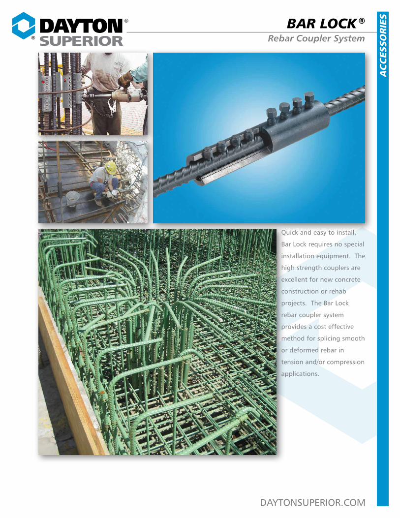
Quick and easy to install,
Bar Lock requires no special
installation equipment. The
high strength couplers are
excellent for new concrete
construction or rehab
projects. The Bar Lock
rebar coupler system
provides a cost effective
method for splicing smooth
or deformed rebar in
tension and/or compression
applications.
®
®
DAYTONSUPERIOR.COM 2
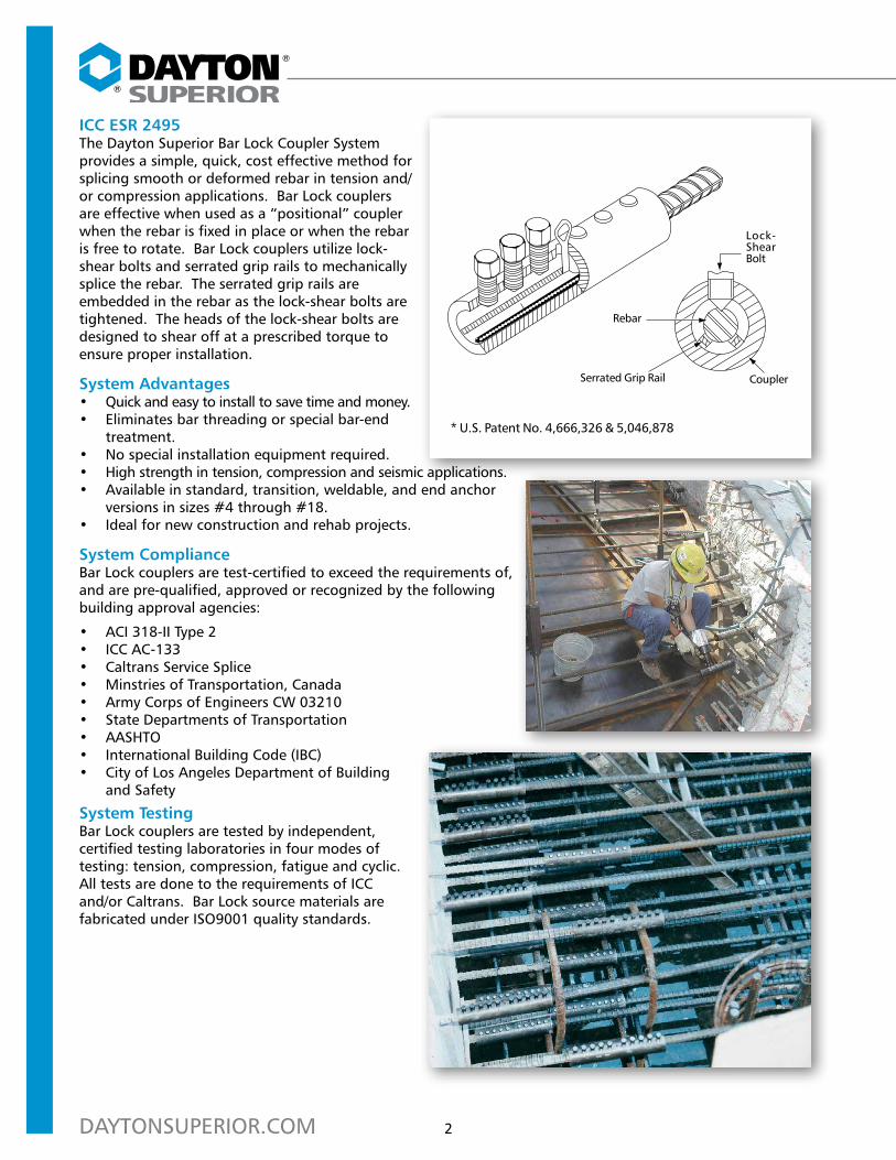
ICC ESR 2495The Dayton Superior Bar Lock Coupler System provides a simple, quick, cost effective method for splicing smooth or deformed rebar in tension and/or compression applications. Bar Lock couplers are effective when used as a “positional” coupler when the rebar is fixed in place or when the rebar is free to rotate. Bar Lock couplers utilize lock-shear bolts and serrated grip rails to mechanically splice the rebar. The serrated grip rails are embedded in the rebar as the lock-shear bolts are tightened. The heads of the lock-shear bolts are designed to shear off at a prescribed torque to ensure proper installation.
System Advantages• Quick and easy to install to save time and money.• Eliminates bar threading or special bar-end
treatment.• No special installation equipment required.• High strength in tension, compression and seismic applications.• Available in standard, transition, weldable, and end anchor
versions in sizes #4 through #18.• Ideal for new construction and rehab projects.
System ComplianceBar Lock couplers are test-certified to exceed the requirements of, and are pre-qualified, approved or recognized by the following building approval agencies:
• ACI 318-II Type 2• ICC AC-133• Caltrans Service Splice• Minstries of Transportation, Canada • Army Corps of Engineers CW 03210• State Departments of Transportation• AASHTO• International Building Code (IBC)• City of Los Angeles Department of Building
and Safety
System TestingBar Lock couplers are tested by independent, certified testing laboratories in four modes of testing: tension, compression, fatigue and cyclic. All tests are done to the requirements of ICC and/or Caltrans. Bar Lock source materials are fabricated under ISO9001 quality standards.
Lock-Shear Bolt
Rebar
* U.S. Patent No. 4,666,326 & 5,046,878
Serrated Grip Rail Coupler
3
Bar Lock Coupler System
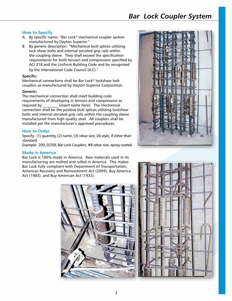
How to SpecifyA. By specific name: “Bar Lock® mechanical coupler system
manufactured by Dayton Superior.”B. By generic description: “Mechanical butt splices utilizing
lock-shear bolts and internal serrated grip rails within the coupling sleeve. They shall exceed the specification requirements for both tension and compression specified by ACI 318 and the Uniform Building Code and be recognized by the International Code Council (ICC).”
Specific:Mechanical connections shall be Bar Lock® lockshear bolt couplers as manufactured by Dayton Superior Corporation.
Generic:The mechanical connection shall meet building code requirements of developing in tension and compression as required by ________ (insert name here). The mechanical connection shall be the positive butt splices utilizing lockshear bolts and internal serrated grip rails within the coupling sleeve manufactured from high quality steel. All couplers shall be installed per the manufacturer’s approved procedures.
How to OrderSpecify: (1) quantity, (2) name, (3) rebar size, (4) style, if other than standard.Example: 200, D250L Bar Lock Couplers, #8 rebar size, epoxy coated.
Made in AmericaBar Lock is 100% made in America. Raw materials used in its manufacturing are melted and rolled in America. This makes Bar Lock fully compliant with Department of Transportation, American Recovery and Reinvestment Act (2009), Buy America Act (1983), and Buy American Act (1933).
®
®
DAYTONSUPERIOR.COM 4
Couplers
Plain Coupler
Epoxy Coated Coupler
Transition Coupler
Structural Steel Connector
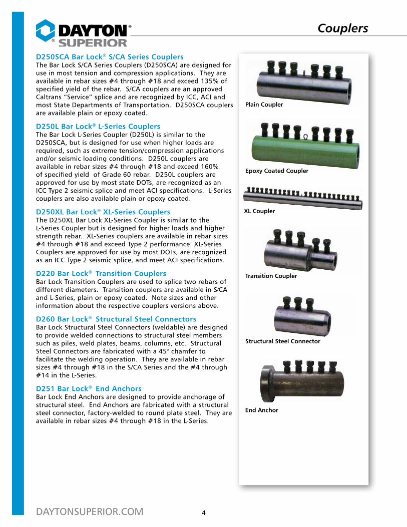
D250SCA Bar Lock® S/CA Series CouplersThe Bar Lock S/CA Series Couplers (D250SCA) are designed for use in most tension and compression applications. They are available in rebar sizes #4 through #18 and exceed 135% of specified yield of the rebar. S/CA couplers are an approved Caltrans “Service” splice and are recognized by ICC, ACI and most State Departments of Transportation. D250SCA couplers are available plain or epoxy coated.
D250L Bar Lock® L-Series CouplersThe Bar Lock L-Series Coupler (D250L) is similar to the D250SCA, but is designed for use when higher loads are required, such as extreme tension/compression applications and/or seismic loading conditions. D250L couplers are available in rebar sizes #4 through #18 and exceed 160% of specified yield of Grade 60 rebar. D250L couplers are approved for use by most state DOTs, are recognized as an ICC Type 2 seismic splice and meet ACI specifications. L-Series couplers are also available plain or epoxy coated.
D250XL Bar Lock® XL-Series CouplersThe D250XL Bar Lock XL-Series Coupler is similar to the L-Series Coupler but is designed for higher loads and higher strength rebar. XL-Series couplers are available in rebar sizes #4 through #18 and exceed Type 2 performance. XL-Series Couplers are approved for use by most DOTs, are recognized as an ICC Type 2 seismic splice, and meet ACI specifications.
D220 Bar Lock® Transition CouplersBar Lock Transition Couplers are used to splice two rebars of different diameters. Transition couplers are available in S∕CA and L-Series, plain or epoxy coated. Note sizes and other information about the respective couplers versions above.
D260 Bar Lock® Structural Steel ConnectorsBar Lock Structural Steel Connectors (weldable) are designed to provide welded connections to structural steel members such as piles, weld plates, beams, columns, etc. Structural Steel Connectors are fabricated with a 45° chamfer to facilitate the welding operation. They are available in rebar sizes #4 through #18 in the S/CA Series and the #4 through #14 in the L-Series.
D251 Bar Lock® End AnchorsBar Lock End Anchors are designed to provide anchorage of structural steel. End Anchors are fabricated with a structural steel connector, factory-welded to round plate steel. They are available in rebar sizes #4 through #18 in the L-Series.
End Anchor
XL Coupler
5
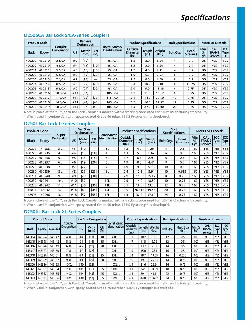
D250SCA Bar Lock S/CA-Series Couplers
Product CodeCoupler
Designation
Bar Size Designation
Barrel Stamp Identification
Product Specifications Bolt Specifications Meets or Exceeds
Black Epoxy US Metric (mm)
CN (M)
Outside Diameter
(in.)Length
(in.)Weight (lbs.) Bolt Qty. Head
Size (in.)Min % Fy*
CAL TRANSService
ICCType
1400200 400210 3 S/CA #3 [10] — 3S...CA 1.3 3.9 1.24 4 0.5 135 YES YES
400200 400210 4 S/CA #4 [13] [10] 4S...CA 1.3 3.9 1.24 4 0.5 135 YES YES400201 400211 5 S/CA #5 [16] [15] 5S...CA 1.7 4.5 2.11 4 0.5 135 YES YES400202 400212 6 S/CA #6 [19] [20] 6S...CA 1.9 6.3 3.57 6 0.5 135 YES YES400203 400213 7 S/CA #7 [22] — 7S...CA 1.9 8.0 4.30 8 0.5 135 YES YES400204 400214 8 S/CA #8 [25] [25] 8S...CA 2.4 10.2 6.10 8 0.625 135 YES YES400205 400215 9 S/CA #9 [29] [30] 9S...CA 2.9 9.0 11.88 6 0.75 135 YES YES400206 400216 10 S/CA #10 [32] — 10S...CA 2.9 11.5 15.17 8 0.75 135 YES YES400207 400217 11 S/CA #11 [36] [35] 11S...CA 3.1 14.0 20.50 10 0.75 135 YES YES400208 400218 14 S/CA #14 [43] [45] 14S...CA 3.5 16.5 27.57 12 0.75 135 YES YES400209 400219 18 S/CA #18 [57] [55] 18S...CA 4.3 27.2 62.00 20 0.75 135 YES YES
Note in place of the “…”, each Bar Lock Coupler is marked with a tracking code used for full manufacturing traceability.* When used in conjunction with epoxy-coated Grade 60 rebar, 125% Fy strength is developed.
D250L Bar Lock L-Series Couplers
Product CodeCoupler
Designation
Bar Size Designation
Barrel Stamp Identification
Product Specifications Bolt Specifications Meets or Exceeds
Black Epoxy US Metric (mm)
CN (M)
Outside Diameter
(in.)Length
(in.)Weight (lbs.) Bolt Qty. Head
Size (in.)Min %
Fy*
CAL TRANSService
ICCType
1
ICC Type
2400327 144988 3 L #3 [10] — 3L... 1.3 4.0 1.67 4 0.5 160 YES YES YES400226 400235 4 L #4 [13] [10] 4L... 1.3 5.5 1.67 6 0.5 160 YES YES YES400227 400236 5 L #5 [16] [15] 5L... 1.7 6.3 2.90 6 0.5 160 YES YES YES400228 400237 6 L #6 [19] [20] 6L... 1.9 8.0 4.44 8 0.5 160 YES YES YES400229 400238 7 L #7 [22] — 7L... 1.9 9.8 5.10 10 0.5 160 YES YES YES400230 400239 8 L #8 [25] [25] 8L... 2.4 12.3 8.94 10 0.625 160 YES YES YES400231 400240 9 L #9 [29] [30] 9L... 2.9 11.5 15.07 8 0.75 160 YES YES YES400232 400241 10 L #10 [32] — 10L... 2.9 14.0 18.50 10 0.75 160 YES YES YES400233 400242 11 L #11 [36] [35] 11L... 3.1 16.5 23.75 12 0.75 160 YES YES YES145831 145832 14 L #14 [43] [45] 14L... 3.5 26.615 39.56 20 0.75 160 YES YES YES
142996 142996 18 L #18 [57] [55] 18L... 4.3 32.2 97.80 24 0.75 160 YES YES YES
Note in place of the “…”, each Bar Lock Coupler is marked with a tracking code used for full manufacturing traceability.* When used in conjunction with epoxy-coated Grade 60 rebar, 135% Fy strength is developed.
D250XL Bar Lock XL-Series Couplers
Product CodeCoupler
Designation
Bar Size DesignationBarrel Stamp Identification
Product Specifications Bolt Specifications Meets or Exceeds
Black Epoxy Galvanized US Metric (mm)
CN (M)
Outside Diameter
(in.)Length
(in.)Weight (lbs.) Bolt Qty. Head Size
(in.)Min %
Fu*CAL
TRANSService
ICCType
1
ICC Type
2145314 145324 145147 4 XL #4 [13] [10] 4XL.... 1.3 10.2 3.10 12 0.5 100 YES YES YES145315 145325 145148 5 XL #5 [16] [15] 5XL.... 1.7 11.5 5.29 12 0.5 100 YES YES YES145316 145326 145149 6 XL #6 [19] [20] 6XL.... 1.9 13.2 7.33 14 0.5 100 YES YES YES145317 145327 145150 7 XL #7 [22] — 7XL.... 1.9 15.0 7.81 16 0.5 100 YES YES YES145318 145328 145151 8 XL #8 [25] [25] 8XL.... 2.4 18.7 13.59 16 0.625 100 YES YES YES145319 145329 145152 9 XL #9 [29] [30] 9XL.... 2.9 19.1 25.03 14 0.75 100 YES YES YES145320 145330 145153 10 XL #10 [32] — 10XL.... 2.9 21.6 28.54 16 0.75 100 YES YES YES145321 145331 145154 11 XL #11 [36] [35] 11XL.... 3.1 24.1 34.69 18 0.75 100 YES YES YES145322 145332 145155 14 XL #14 [43] [45] 14XL.... 3.5 29.1 48.14 22 0.75 100 YES YES YES145323 145333 145156 18 XL #18 [57] [55] 18XL.... 4.3 44.8 136.06 34 0.75 100 YES YES YES
Note in place of the “…”, each Bar Lock Coupler is marked with a tracking code used for full manufacturing traceability.* When used in conjunction with epoxy-coated Grade 75/80 rebar, 135% Fy strength is developed.
Specifications
®
®
DAYTONSUPERIOR.COM 6
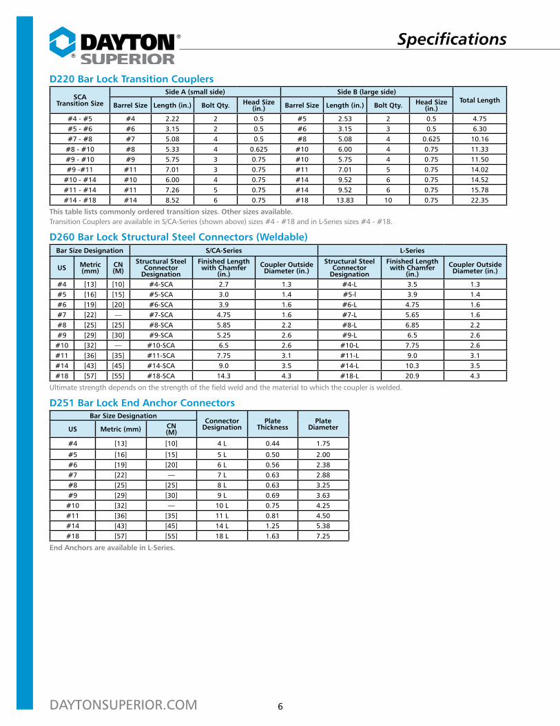
D220 Bar Lock Transition Couplers
SCA Transition Size
Side A (small side) Side B (large side)Total Length
Barrel Size Length (in.) Bolt Qty. Head Size (in.) Barrel Size Length (in.) Bolt Qty. Head Size
(in.)#4 - #5 #4 2.22 2 0.5 #5 2.53 2 0.5 4.75#5 - #6 #6 3.15 2 0.5 #6 3.15 3 0.5 6.30#7 - #8 #7 5.08 4 0.5 #8 5.08 4 0.625 10.16
#8 - #10 #8 5.33 4 0.625 #10 6.00 4 0.75 11.33#9 - #10 #9 5.75 3 0.75 #10 5.75 4 0.75 11.50#9 -#11 #11 7.01 3 0.75 #11 7.01 5 0.75 14.02
#10 - #14 #10 6.00 4 0.75 #14 9.52 6 0.75 14.52#11 - #14 #11 7.26 5 0.75 #14 9.52 6 0.75 15.78#14 - #18 #14 8.52 6 0.75 #18 13.83 10 0.75 22.35
This table lists commonly ordered transition sizes. Other sizes available.Transition Couplers are available in S/CA-Series (shown above) sizes #4 - #18 and in L-Series sizes #4 - #18.
D260 Bar Lock Structural Steel Connectors (Weldable)Bar Size Designation S/CA-Series L-Series
US Metric (mm)
CN (M)
Structural Steel Connector
Designation
Finished Length with Chamfer
(in.)Coupler Outside Diameter (in.)
Structural Steel Connector
Designation
Finished Length with Chamfer
(in.)Coupler Outside Diameter (in.)
#4 [13] [10] #4-SCA 2.7 1.3 #4-L 3.5 1.3#5 [16] [15] #5-SCA 3.0 1.4 #5-l 3.9 1.4#6 [19] [20] #6-SCA 3.9 1.6 #6-L 4.75 1.6#7 [22] — #7-SCA 4.75 1.6 #7-L 5.65 1.6#8 [25] [25] #8-SCA 5.85 2.2 #8-L 6.85 2.2#9 [29] [30] #9-SCA 5.25 2.6 #9-L 6.5 2.6
#10 [32] — #10-SCA 6.5 2.6 #10-L 7.75 2.6#11 [36] [35] #11-SCA 7.75 3.1 #11-L 9.0 3.1#14 [43] [45] #14-SCA 9.0 3.5 #14-L 10.3 3.5#18 [57] [55] #18-SCA 14.3 4.3 #18-L 20.9 4.3
Ultimate strength depends on the strength of the field weld and the material to which the coupler is welded.
D251 Bar Lock End Anchor ConnectorsBar Size Designation
Connector Designation
Plate Thickness
Plate DiameterUS Metric (mm) CN
(M)
#4 [13] [10] 4 L 0.44 1.75
#5 [16] [15] 5 L 0.50 2.00#6 [19] [20] 6 L 0.56 2.38#7 [22] — 7 L 0.63 2.88#8 [25] [25] 8 L 0.63 3.25#9 [29] [30] 9 L 0.69 3.63
#10 [32] — 10 L 0.75 4.25#11 [36] [35] 11 L 0.81 4.50#14 [43] [45] 14 L 1.25 5.38#18 [57] [55] 18 L 1.63 7.25
End Anchors are available in L-Series.
Specifications
7
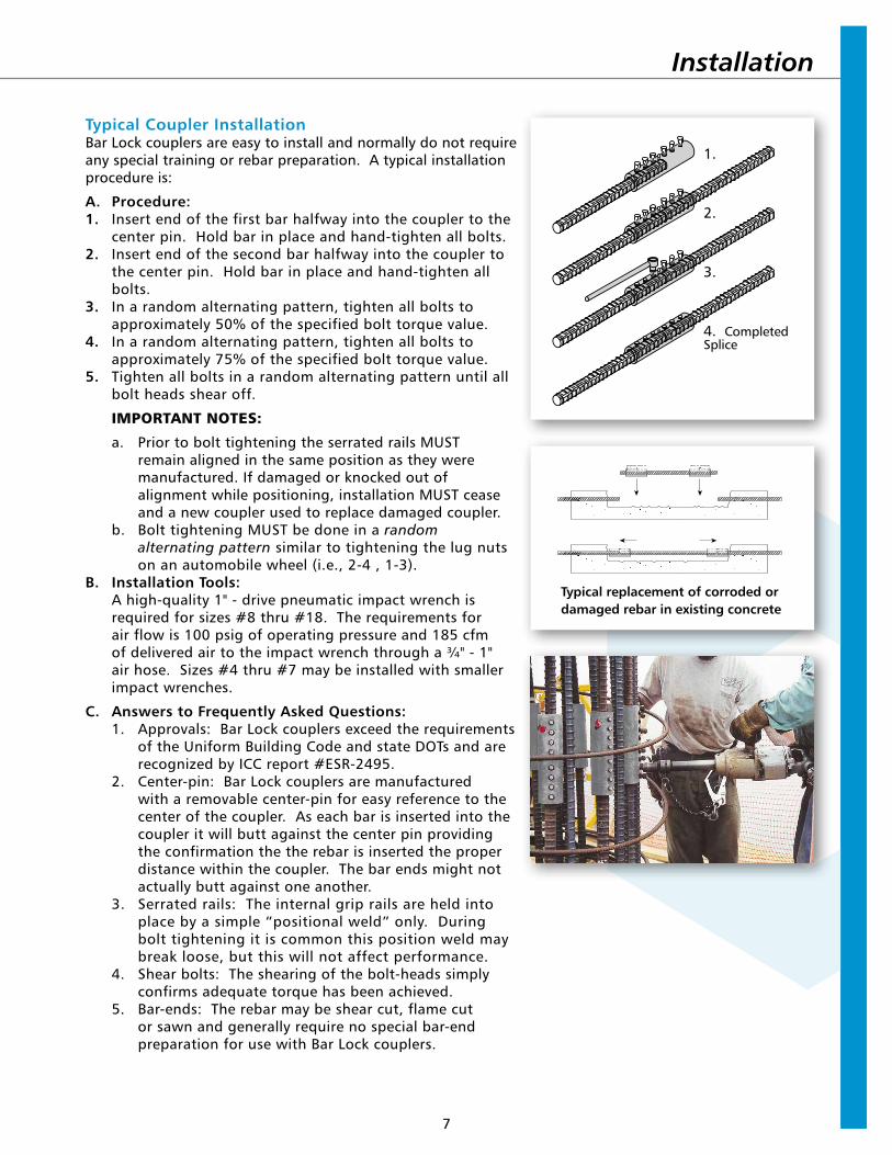
Typical Coupler InstallationBar Lock couplers are easy to install and normally do not require any special training or rebar preparation. A typical installation procedure is:
A. Procedure:1. Insert end of the first bar halfway into the coupler to the
center pin. Hold bar in place and hand-tighten all bolts.2. Insert end of the second bar halfway into the coupler to
the center pin. Hold bar in place and hand-tighten all bolts.
3. In a random alternating pattern, tighten all bolts to approximately 50% of the specified bolt torque value.
4. In a random alternating pattern, tighten all bolts to approximately 75% of the specified bolt torque value.
5. Tighten all bolts in a random alternating pattern until all bolt heads shear off.
IMPORTANT NOTES:
a. Prior to bolt tightening the serrated rails MUST remain aligned in the same position as they were manufactured. If damaged or knocked out of alignment while positioning, installation MUST cease and a new coupler used to replace damaged coupler.
b. Bolt tightening MUST be done in a random alternating pattern similar to tightening the lug nuts on an automobile wheel (i.e., 2-4 , 1-3).
B. Installation Tools:A high-quality 1" - drive pneumatic impact wrench is required for sizes #8 thru #18. The requirements for air flow is 100 psig of operating pressure and 185 cfm of delivered air to the impact wrench through a ¾" - 1" air hose. Sizes #4 thru #7 may be installed with smaller impact wrenches.
C. Answers to Frequently Asked Questions:1. Approvals: Bar Lock couplers exceed the requirements
of the Uniform Building Code and state DOTs and are recognized by ICC report #ESR-2495.
2. Center-pin: Bar Lock couplers are manufactured with a removable center-pin for easy reference to the center of the coupler. As each bar is inserted into the coupler it will butt against the center pin providing the confirmation the the rebar is inserted the proper distance within the coupler. The bar ends might not actually butt against one another.
3. Serrated rails: The internal grip rails are held into place by a simple “positional weld” only. During bolt tightening it is common this position weld may break loose, but this will not affect performance.
4. Shear bolts: The shearing of the bolt-heads simply confirms adequate torque has been achieved.
5. Bar-ends: The rebar may be shear cut, flame cut or sawn and generally require no special bar-end preparation for use with Bar Lock couplers.
Typical replacement of corroded or damaged rebar in existing concrete
1.
2.
3.
4. Completed Splice
Installation
W W W . D A Y T O N S U P E R I O R . C O M • B U I L D I N G S T R E N G T HCopyright © 2014 Dayton Superior Corporation, All Rights Reserved
®
®
CORPORATE HEADQUARTERS1125 Byers RoadMiamisburg, OH 45342937-866-0711
ACCESSORIES AND CHEMICALSCustomer Service: 888-977-9600Technical Assistance: [email protected]
FORMING PRODUCTSCustomer Service: 800-800-7966Technical Assistance: [email protected]
BRIDGE DECK FORMINGAdjustable Joist HangersBridge Overhang BracketsHaunch and Fillet FormingPres-Steel, Coil Rod and Con-Beam
HangersScreed Supports
CHEMICALSBond BreakersCleaners / StrippersConcrete Repair/RestorationCuring Compounds / SealersEpoxiesFloor LevelersForm Release AgentsGroutHardeners / Industrial ToppingsLiquid DensifiersSurface Retarders
FORMING AND SHORINGAluminum ShoringGanged FormworkGarage Beam SystemHandset FormworkHighway FormsJump FormsModular Deck ShoringOne Sided FramesSelf Spanning FormsSteel Frame Shoring
FORMLINERSABS PlasticPolystyrene Plastic
PAVINGDowel Bar Expansion CapsDowel Bar Retrofit SystemElastomeric and Hot Pour Joint SealMetal Keyway Form SystemsTie Bar AssembliesTransverse Bar AssembliesWelded Dowel AssembliesWire Baskets without Dowels
PRECASTAnchors and Lift SystemsCoil / Ferrule InsertsCore PlugsMagnetsPrecast FormsRustications/ChamfersSandwich Panel ConnectorShear Connectors Slotted Inserts
REBAR SPLICINGForged Dowel Bar CouplersLockshear Bolt CouplersShear Resistance ProductsStraight Thread CouplersTaper Thread Couplers
REBAR SUPPORTSConcrete Dobies Continuous Plastic and Steel
Bar SupportsIndividual Plastic and Steel
Bar SupportsMesh ChairsPaving ChairsSide Form Spacers
TIES AND ACCESSORIESModular Form TiesSingle Waler SystemTies and Accessories
TILT-UPBraces and Brace AnchorsHelical Ground AnchorsSetting PlugsStrongback SystemTilt-Up Anchors and Lifting Systems
CONCRETE ACCESSORIESAccubrace®
Aztec®
Bar Lock®
Corewall®
Fleet-Lift™Swift Lift®
Taper-Lock®
CONSTRUCTION CHEMICALSUnitex®
FORMING PRODUCTSSymons®
Max-A-Form®
Steel-Ply®
Sym-Ply®
DAYTON SUPERIOR BRANDS
DAYTON SUPERIOR PRODUCTS
CONTACT INFORMATION
DS5002/14
$1


![D250SCA BAR LOCK COUPLER - TruSupply.com Information/Dayton...Aug 02, 2017 · 400209 #18 [57MM] 64.00 LB EPOXY (MADE IN USA) Product Code Description Weight 400210 #3 [10MM] 1.25](https://img.pdfslide.net/doc/110x75/6016023f3d7f4353f778cd87/d250sca-bar-lock-coupler-informationdayton-aug-02-2017-400209-18-57mm.jpg)