Embed Size (px)
Citation preview
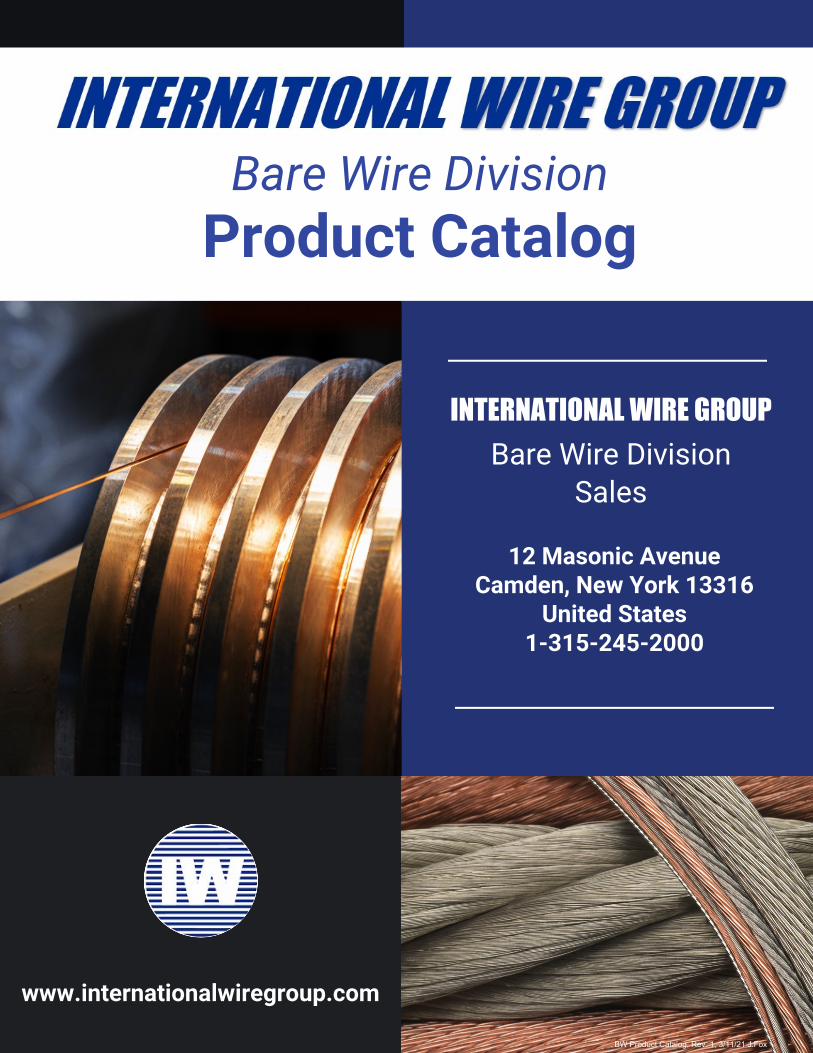
Product Catalog
INTERNATIONAL WIRE GROUP
12 Masonic AvenueCamden, New York 13316
United States1-315-245-2000
Bare Wire DivisionSales
Bare Wire Division
www.internationalwiregroup.com
BW Product Catalog, Rev. 1, 3/11/21 J.Fox
Page 2
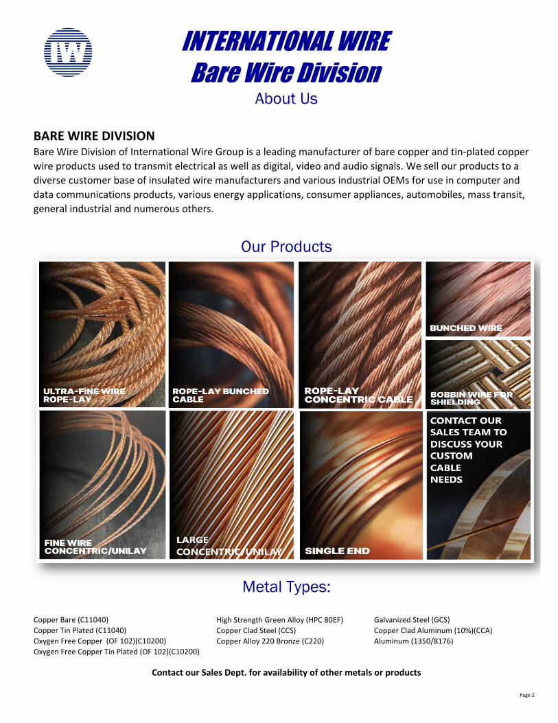
High Strength Green Alloy (HPC 80EF)Copper Clad Steel (CCS) Copper Clad Aluminum (10%)(CCA)Copper Alloy 220 Bronze (C220) Aluminum (1350/8176)
INTERNATIONAL WIREBare Wire Division
About Us
BARE WIRE DIVISIONBare Wire Division of International Wire Group is a leading manufacturer of bare copper and tin-plated copper wire products used to transmit electrical as well as digital, video and audio signals. We sell our products to a diverse customer base of insulated wire manufacturers and various industrial OEMs for use in computer and data communications products, various energy applications, consumer appliances, automobiles, mass transit, general industrial and numerous others.
Our Products
Copper Tin Plated (C11040)Oxygen Free Copper (OF 102)(C10200)Oxygen Free Copper Tin Plated (OF 102)(C10200)
Contact our Sales Dept. for availability of other metals or products
Metal Types:
Galvanized Steel (GCS)Copper Bare (C11040)
Page 3
Bare Single End (Solid) ASTM B1,B3 Pg. 4
Tinned Single End (Solid) ASTM B3,B33 Pg. 5
Bobbins ASTM B3,B33 Pg. 6
7 Strand Concentric Stranded Conductors ASTM B-3 (Bare), ASTM B-33 (Tinned), ASTM B8, ASTM B-286 Pg. 7
19, 37 Strand Concentric Stranded Conductors ASTM B-3 (Bare), ASTM B-33 (Tinned), ASTM B8, ASTM B-287 Pg. 8
61,91,127,169 Strand Concentric Stranded Conductors ASTM B-3 (Bare), ASTM B-33 (Tinned), ASTM B8, ASTM B-286 Pg. 9
Compact Round Concentric Bare Copper ASTM B-496 Pg. 10
19-Strand Unilay Conductors Bare Copper ASTM B-3, ASTM B-8, ASTM B-286 Pg. 11
19-Strand Unilay Conductors Tinned Copper ASTM B-33, ASTM B-8, ASTM B-286 Pg. 12
19-Strand Combination Unilay Conductors ASTM B-33, ASTM B-8, ASTM B-787 Pg. 13
Semi Concentric Stranded Conductors ASTM B8 Pg. 14
Bonded Products (Topcoat, Prebond, Overcoat) ASTM B-33, ASTM B-286, ASTM B-470 Pg. 15
Bunch Stranded Copper Conductors ASTM B-3 (Bare) B-33 (Tin), ASTM B174 Pg. 16,17,18
Smooth Bunch Stranded Copper Conductors ASTM B-3 (Bare), B33 (Tin), ASTM B-8, ASTM B174 (As Applicable) Pg. 19
Water Block Strand / Anti-Capillary - Bare Copper ASTM B-3 (Bare), ASTM B-33 (Tinned), ASTM B-8 Pg. 20
Copper Clad Steel Wire ASTM B452 and Others as Applicable to Construction Type Pg. 21
Concentric Ropes Bare & Tinned Copper, Class G ASTM B-3 (Bare), ASTM B-33 (Tinned), ASTM B-173 Class G Pg. 22
Concentric Ropes Bare & Tinned Copper, Class H ASTM B-3 (Bare), ASTM B-33 (Tinned), ASTM B-173 Class H Pg. 23
Miscellaneous Concentric Ropes Copper ASTM B-3 (Bare), ASTM B-33 (Tinned), ASTM B-173 Pg. 24
24 AWG Bunch Ropes Bare Copper ASTM B-3, ASTM B-172 Class I Pg. 25
24 AWG Bunch Ropes Tinned Copper ASTM B-33, ASTM B-172 Class I Pg. 26
25 & 27 AWG Bunch Ropes Copper ASTM B-3 (Bare), ASTM B-33 (Tinned), ASTM B-172 Pg. 27
28 & 29 AWG Bunch Ropes Copper ASTM B-3 (Bare), ASTM B-33 (Tinned), ASTM B-172 Pg. 28
30 AWG Bunch Ropes Bare Copper ASTM B-3, ASTM B-172 Class K Pg. 29,30
30 AWG Bunch Ropes Tinned Copper ASTM B-33, ASTM B-172 Class K Pg. 31
32 AWG Bunch Ropes Copper ASTM B-3 (Bare), ASTM B-33 (Tinned), ASTM B-172 Pg. 32
34 AWG Bunch Ropes Bare Copper ASTM B-3, ASTM B-172 Class M Pg. 33
34 AWG Bunch Ropes Tinned Copper ASTM B-33, ASTM B-172 Class M Pg. 34
36 AWG Bunch Ropes Bare Copper ASTM B-3, ASTM B-172 Class O Pg. 35
36 AWG Bunch Ropes Tinned Copper ASTM B-33, ASTM B-172 Class O Pg. 36
40 AWG Bunch Ropes Bare Copper ASTM B-3, ASTM B-172 Class Q Pg. 37
40 AWG Bunch Ropes Tinned Copper ASTM B-33, ASTM B-172 Class Q Pg. 38
42 AWG Fine Wire Bunch Ropes Copper ASTM B-3 (Bare), ASTM B-33 (Tinned), ASTM B-738 Class R Pg. 39
44 AWG Ultra Fine Wire Bunch Ropes Bare Copper ASTM B-3, ASTM B-738 Class S Pg. 40
44 AWG Ultra Fine Wire Bunch Ropes Tin Copper ASTM B-33, ASTM B-738 Class S Pg. 41
Contacts & Locations Pg. 42Reel Dimensions & Capacities Pg. 43American Wire Gauge Chart Pg. 44Engineering Resources Pg. 45Glossary of Terms For Wire & Cable Pg. 46,47Wire & Cable Facts - Lay Direction and Length Pg. 48,49Wire & Cable Facts - Strand Configurations Pg. 50,51,52
Index
INTERNATIONAL WIREBare Wire Division
Product Catalog
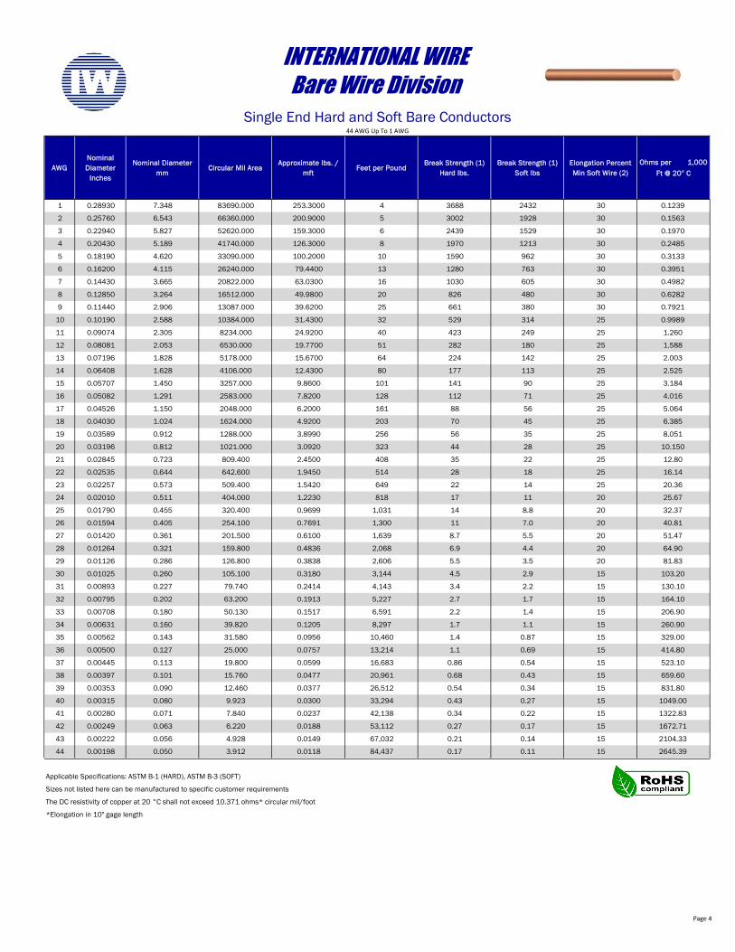
AWGNominal Diameter
Inches
Nominal Diameter mm
Circular Mil AreaApproximate lbs. /
mftFeet per Pound
Break Strength (1) Hard lbs.
Break Strength (1) Soft lbs
Elongation Percent Min Soft Wire (2)
Ohms per 1,000 Ft @ 20° C
1 0.28930 7.348 83690.000 253.3000 4 3688 2432 30 0.1239
2 0.25760 6.543 66360.000 200.9000 5 3002 1928 30 0.1563
3 0.22940 5.827 52620.000 159.3000 6 2439 1529 30 0.1970
4 0.20430 5.189 41740.000 126.3000 8 1970 1213 30 0.2485
5 0.18190 4.620 33090.000 100.2000 10 1590 962 30 0.3133
6 0.16200 4.115 26240.000 79.4400 13 1280 763 30 0.3951
7 0.14430 3.665 20822.000 63.0300 16 1030 605 30 0.4982
8 0.12850 3.264 16512.000 49.9800 20 826 480 30 0.6282
9 0.11440 2.906 13087.000 39.6200 25 661 380 30 0.7921
10 0.10190 2.588 10384.000 31.4300 32 529 314 25 0.9989
11 0.09074 2.305 8234.000 24.9200 40 423 249 25 1.260
12 0.08081 2.053 6530.000 19.7700 51 282 180 25 1.588
13 0.07196 1.828 5178.000 15.6700 64 224 142 25 2.003
14 0.06408 1.628 4106.000 12.4300 80 177 113 25 2.525
15 0.05707 1.450 3257.000 9.8600 101 141 90 25 3.184
16 0.05082 1.291 2583.000 7.8200 128 112 71 25 4.016
17 0.04526 1.150 2048.000 6.2000 161 88 56 25 5.064
18 0.04030 1.024 1624.000 4.9200 203 70 45 25 6.385
19 0.03589 0.912 1288.000 3.8990 256 56 35 25 8.051
20 0.03196 0.812 1021.000 3.0920 323 44 28 25 10.150
21 0.02845 0.723 809.400 2.4500 408 35 22 25 12.80
22 0.02535 0.644 642.600 1.9450 514 28 18 25 16.14
23 0.02257 0.573 509.400 1.5420 649 22 14 25 20.36
24 0.02010 0.511 404.000 1.2230 818 17 11 20 25.67
25 0.01790 0.455 320.400 0.9699 1,031 14 8.8 20 32.37
26 0.01594 0.405 254.100 0.7691 1,300 11 7.0 20 40.81
27 0.01420 0.361 201.500 0.6100 1,639 8.7 5.5 20 51.47
28 0.01264 0.321 159.800 0.4836 2,068 6.9 4.4 20 64.90
29 0.01126 0.286 126.800 0.3838 2,606 5.5 3.5 20 81.83
30 0.01025 0.260 105.100 0.3180 3,144 4.5 2.9 15 103.20
31 0.00893 0.227 79.740 0.2414 4,143 3.4 2.2 15 130.10
32 0.00795 0.202 63.200 0.1913 5,227 2.7 1.7 15 164.10
33 0.00708 0.180 50.130 0.1517 6,591 2.2 1.4 15 206.90
34 0.00631 0.160 39.820 0.1205 8,297 1.7 1.1 15 260.90
35 0.00562 0.143 31.580 0.0956 10,460 1.4 0.87 15 329.00
36 0.00500 0.127 25.000 0.0757 13,214 1.1 0.69 15 414.80
37 0.00445 0.113 19.800 0.0599 16,683 0.86 0.54 15 523.10
38 0.00397 0.101 15.760 0.0477 20,961 0.68 0.43 15 659.60
39 0.00353 0.090 12.460 0.0377 26,512 0.54 0.34 15 831.80
40 0.00315 0.080 9.923 0.0300 33,294 0.43 0.27 15 1049.00
41 0.00280 0.071 7.840 0.0237 42,138 0.34 0.22 15 1322.83
42 0.00249 0.063 6.220 0.0188 53,112 0.27 0.17 15 1672.71
43 0.00222 0.056 4.928 0.0149 67,032 0.21 0.14 15 2104.33
44 0.00198 0.050 3.912 0.0118 84,437 0.17 0.11 15 2645.39
*Elongation in 10" gage length
INTERNATIONAL WIREBare Wire Division
Single End Hard and Soft Bare Conductors
Applicable Specifications: ASTM B-1 (HARD), ASTM B-3 (SOFT)
Sizes not listed here can be manufactured to specific customer requirements
The DC resistivity of copper at 20 °C shall not exceed 10.371 ohms* circular mil/foot
44 AWG Up To 1 AWG
Page 4
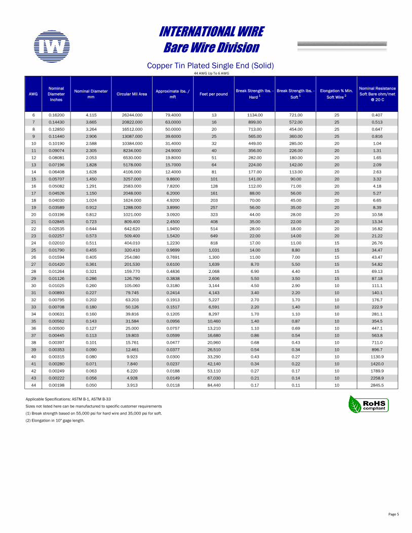
AWGNominal Diameter
Inches
Nominal Diameter mm
Circular Mil AreaApproximate lbs. /
mftFeet per pound
Break Strength lbs. - Hard 1
Break Strength lbs. - Soft 1
Elongation % Min. Soft Wire 2
Nominal Resistance Soft Bare ohm/met
@ 20 C
6 0.16200 4.115 26244.000 79.4000 13 1134.00 721.00 25 0.407
7 0.14430 3.665 20822.000 63.0000 16 899.00 572.00 25 0.513
8 0.12850 3.264 16512.000 50.0000 20 713.00 454.00 25 0.647
9 0.11440 2.906 13087.000 39.6000 25 565.00 360.00 25 0.816
10 0.10190 2.588 10384.000 31.4000 32 449.00 285.00 20 1.04
11 0.09074 2.305 8234.000 24.9000 40 356.00 226.00 20 1.31
12 0.08081 2.053 6530.000 19.8000 51 282.00 180.00 20 1.65
13 0.07196 1.828 5178.000 15.7000 64 224.00 142.00 20 2.09
14 0.06408 1.628 4106.000 12.4000 81 177.00 113.00 20 2.63
15 0.05707 1.450 3257.000 9.8600 101 141.00 90.00 20 3.32
16 0.05082 1.291 2583.000 7.8200 128 112.00 71.00 20 4.18
17 0.04526 1.150 2048.000 6.2000 161 88.00 56.00 20 5.27
18 0.04030 1.024 1624.000 4.9200 203 70.00 45.00 20 6.65
19 0.03589 0.912 1288.000 3.8990 257 56.00 35.00 20 8.39
20 0.03196 0.812 1021.000 3.0920 323 44.00 28.00 20 10.58
21 0.02845 0.723 809.400 2.4500 408 35.00 22.00 20 13.34
22 0.02535 0.644 642.620 1.9450 514 28.00 18.00 20 16.82
23 0.02257 0.573 509.400 1.5420 649 22.00 14.00 20 21.22
24 0.02010 0.511 404.010 1.2230 818 17.00 11.00 15 26.76
25 0.01790 0.455 320.410 0.9699 1,031 14.00 8.80 15 34.47
26 0.01594 0.405 254.080 0.7691 1,300 11.00 7.00 15 43.47
27 0.01420 0.361 201.530 0.6100 1,639 8.70 5.50 15 54.82
28 0.01264 0.321 159.770 0.4836 2,068 6.90 4.40 15 69.13
29 0.01126 0.286 126.790 0.3838 2,606 5.50 3.50 15 87.18
30 0.01025 0.260 105.060 0.3180 3,144 4.50 2.90 10 111.1
31 0.00893 0.227 79.745 0.2414 4,143 3.40 2.20 10 140.1
32 0.00795 0.202 63.203 0.1913 5,227 2.70 1.70 10 176.7
33 0.00708 0.180 50.126 0.1517 6,591 2.20 1.40 10 222.9
34 0.00631 0.160 39.816 0.1205 8,297 1.70 1.10 10 281.1
35 0.00562 0.143 31.584 0.0956 10,460 1.40 0.87 10 354.5
36 0.00500 0.127 25.000 0.0757 13,210 1.10 0.69 10 447.1
37 0.00445 0.113 19.803 0.0599 16,680 0.86 0.54 10 563.8
38 0.00397 0.101 15.761 0.0477 20,960 0.68 0.43 10 711.0
39 0.00353 0.090 12.461 0.0377 26,510 0.54 0.34 10 896.7
40 0.00315 0.080 9.923 0.0300 33,290 0.43 0.27 10 1130.9
41 0.00280 0.071 7.840 0.0237 42,140 0.34 0.22 10 1420.0
42 0.00249 0.063 6.220 0.0188 53,110 0.27 0.17 10 1789.9
43 0.00222 0.056 4.928 0.0149 67,030 0.21 0.14 10 2258.9
44 0.00198 0.050 3.913 0.0118 84,440 0.17 0.11 10 2845.5
(2) Elongation in 10" gage length.
INTERNATIONAL WIREBare Wire Division
Copper Tin Plated Single End (Solid)
Applicable Specifications: ASTM B-1, ASTM B-33
Sizes not listed here can be manufactured to specific customer requirements
(1) Break strength based on 55,000 psi for hard wire and 35,000 psi for soft.
44 AWG Up To 6 AWG
Page 5
Page 6
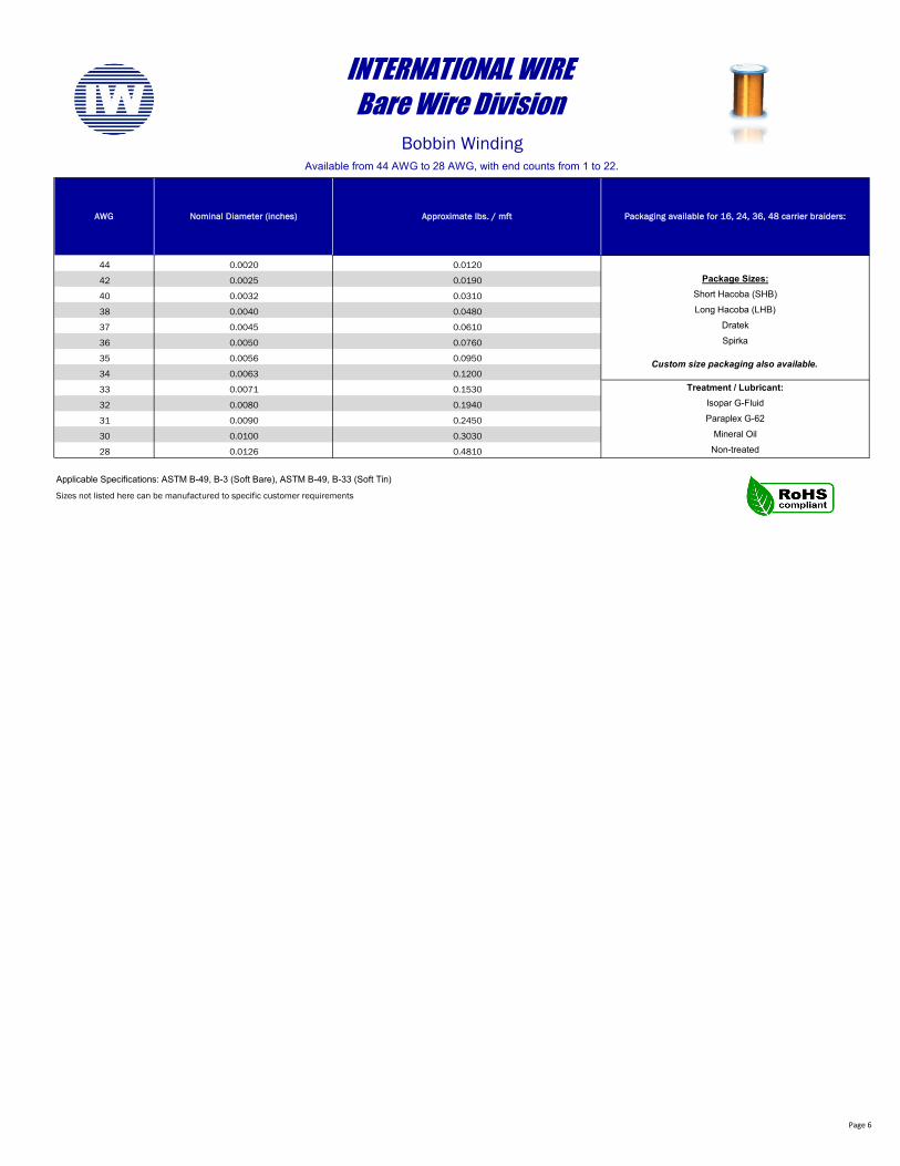
Treatment / Lubricant:
Custom size packaging also available.
Packaging available for 16, 24, 36, 48 carrier braiders:
Package Sizes:Short Hacoba (SHB)Long Hacoba (LHB)
Dratek
0.0090
0.0100
Sizes not listed here can be manufactured to specific customer requirements
Applicable Specifications: ASTM B-49, B-3 (Soft Bare), ASTM B-49, B-33 (Soft Tin)
Paraplex G-62Mineral Oil
Non-treated
0.0032
0.0040
0.0045
0.0126
INTERNATIONAL WIREBare Wire Division
Bobbin WindingAvailable from 44 AWG to 28 AWG, with end counts from 1 to 22.
0.0050
0.0056
0.0063
0.0071
0.0080
0.0020
Isopar G-Fluid
Spirka
32
31
30
28
Nominal Diameter (inches)
37
36
35
34
33
AWG
44
42
40
38
0.0025
Approximate lbs. / mft
0.0120
0.4810
0.3030
0.2450
0.1940
0.1530
0.1200
0.0950
0.0760
0.0610
0.0480
0.0310
0.0190
Page 7
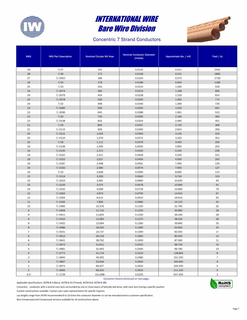
AWG IWG Part Description Nominal Circular Mil AreaNominal Conductor Diameter
(inches)Approximate lbs. / mft Feet / Lb
29 7/37 142 0.0132 0.411 2432
28 7/36 175 0.0148 0.531 1882
27 7/.0052 189 0.0154 0.575 1739
26 7/34 278 0.0189 0.843 1186
25 7/33 353 0.0210 1.090 918
24 7/.0074 383 0.0215 1.168 856
24 7/.0076 404 0.0228 1.229 814
24 7/.0078 426 0.0235 1.292 774
24 7/32 448 0.0240 1.369 730
23 7/.0085 506 0.0255 1.534 652
22 7/.0096 645 0.0288 1.961 510
22 7/30 700 0.0300 2.160 463
22 7/.0108 816 0.0324 2.490 401
21 7/29 894 0.0337 2.720 368
21 7/.0115 926 0.0340 2.810 356
20 7/.0121 1,025 0.0363 3.130 319
20 7/.0124 1,076 0.0372 3.320 301
20 7/28 1,111 0.0378 3.400 294
19 7/.0136 1,295 0.0000 3.950 253
19 7/.0140 1,372 0.0420 4.240 236
19 7/.0142 1,411 0.0426 4.330 231
18 7/.0152 1,617 0.0456 4.930 203
16 7/.0187 2,448 0.0561 7.490 134
16 7/.0192 2,580 0.0576 7.900 127
16 7/24 2,828 0.0590 8.660 115
15 7/.0214 3,206 0.0640 9.740 103
15 7/.0223 3,481 0.0660 10.630 94
15 7/.0226 3,575 0.0678 10.990 91
14 7/.0242 4,099 0.0726 12.660 79
13 7/.0264 4,879 0.0790 14.910 67
12 7/.0305 6,512 0.0915 19.910 50
11 7/.0335 7,856 0.0980 24.120 42
10 7/.0385 10,376 0.1150 31.760 32
9 7/.0409 11,710 0.1230 35.890 28
9 7/.0411 11,824 0.1230 36.240 28
9 7/.0424 12,584 0.1270 38.520 26
9 7/.0432 13,064 0.1260 39.840 25
8 7/.0486 16,534 0.1460 50.600 20
7 7/.0531 19,737 0.1590 60.450 17
6 7/.0612 26,218 0.1840 80.000 13
6 7/.0641 28,762 0.1900 87.560 11
5 7/.0672 31,611 0.2020 96.700 10
5 7/.0681 32,463 0.2050 99.780 10
4 7/.0772 41,719 0.2310 128.800 8
3 7/.0840 49,392 0.2480 151.200 7
3 7/.0867 52,618 0.2600 160.900 6
2 7/.0974 66,407 0.2920 205.000 5
2 7/.0993 69,023 0.2920 211.100 5
4/0 7/.1739 211,688 0.5220 647.400 2
Applicable Specifications: ASTM B-3 (Bare), ASTM B-33 (Tinned), ASTM B-8, ASTM B-286
Concentric - conductor with a central core wire surrounded by one or more layers of helically laid wires, with each wire having a specific position
Lay lengths range from ASTM recommended 8 to 16 times the conductor diameter or can be manufactured to customer specification.
Custom constructions available. Contact your sales representative for specific inquires.
Non-Compressed and Compressed versions available for all constructions above.
INTERNATIONAL WIREBare Wire Division
Concentric 7 Strand Conductors
Concentric Strand Continued on next page…
Page 8
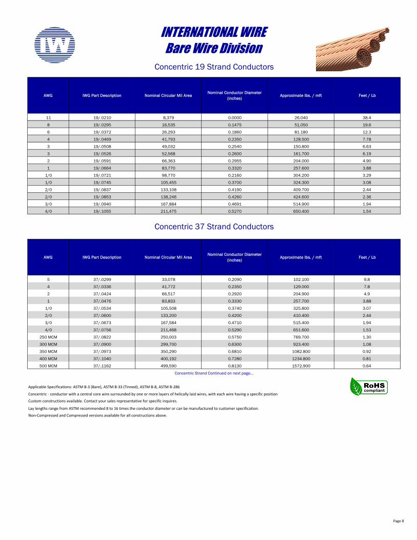
AWG IWG Part Description Nominal Circular Mil AreaNominal Conductor Diameter
(inches)Approximate lbs. / mft Feet / Lb
11 19/.0210 8,379 0.0000 26.040 38.4
8 19/.0295 16,535 0.1475 51.050 19.6
6 19/.0372 26,293 0.1860 81.180 12.3
4 19/.0469 41,793 0.2350 128.500 7.78
3 19/.0508 49,032 0.2540 150.800 6.63
3 19/.0526 52,568 0.2600 161.700 6.19
2 19/.0591 66,363 0.2955 204.000 4.90
1 19/.0664 83,770 0.3320 257.600 3.88
1/0 19/.0721 98,770 0.2160 304.200 3.29
1/0 19/.0745 105,455 0.3700 324.300 3.08
2/0 19/.0837 133,108 0.4190 409.700 2.44
2/0 19/.0853 138,246 0.4260 424.600 2.36
3/0 19/.0940 167,884 0.4691 514.900 1.94
4/0 19/.1055 211,475 0.5270 650.400 1.54
AWG IWG Part Description Nominal Circular Mil AreaNominal Conductor Diameter
(inches)Approximate lbs. / mft Feet / Lb
5 37/.0299 33,078 0.2090 102.100 9.8
4 37/.0336 41,772 0.2350 129.000 7.8
2 37/.0424 66,517 0.2920 204.900 4.9
1 37/.0476 83,833 0.3330 257.700 3.88
1/0 37/.0534 105,508 0.3740 325.800 3.07
2/0 37/.0600 133,200 0.4200 410.400 2.44
3/0 37/.0673 167,584 0.4710 515.400 1.94
4/0 37/.0756 211,468 0.5290 651.600 1.53
250 MCM 37/.0822 250,003 0.5750 769.700 1.30
300 MCM 37/.0900 299,700 0.6300 923.400 1.08
350 MCM 37/.0973 350,290 0.6810 1082.800 0.92
400 MCM 37/.1040 400,192 0.7280 1234.800 0.81
500 MCM 37/.1162 499,590 0.8130 1572.900 0.64
Applicable Specifications: ASTM B-3 (Bare), ASTM B-33 (Tinned), ASTM B-8, ASTM B-286
Concentric - conductor with a central core wire surrounded by one or more layers of helically laid wires, with each wire having a specific position
Lay lengths range from ASTM recommended 8 to 16 times the conductor diameter or can be manufactured to customer specification.
Non-Compressed and Compressed versions available for all constructions above.
Concentric Strand Continued on next page…
Concentric 37 Strand Conductors
INTERNATIONAL WIREBare Wire Division
Concentric 19 Strand Conductors
Custom constructions available. Contact your sales representative for specific inquires.
Page 9
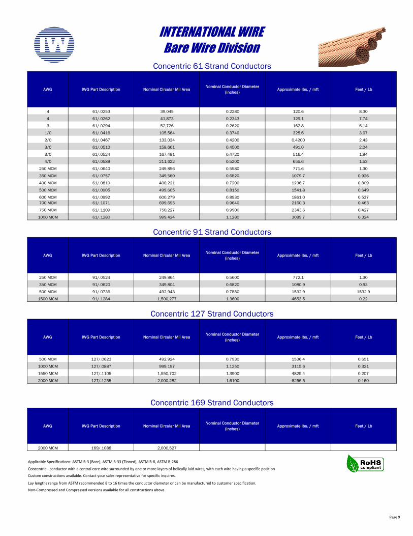
AWG IWG Part Description Nominal Circular Mil AreaNominal Conductor Diameter
(inches)Approximate lbs. / mft Feet / Lb
4 61/.0253 39,045 0.2280 120.6 8.30
4 61/.0262 41,873 0.2343 129.1 7.74
3 61/.0294 52,726 0.2620 162.8 6.14
1/0 61/.0416 105,564 0.3740 325.6 3.07
2/0 61/.0467 133,034 0.4200 0.4200 2.43
3/0 61/.0510 158,661 0.4500 491.0 2.04
3/0 61/.0524 167,491 0.4720 516.4 1.94
4/0 61/.0589 211,622 0.5200 655.6 1.53
250 MCM 61/.0640 249,856 0.5580 771.6 1.30
350 MCM 61/.0757 349,560 0.6820 1079.7 0.926
400 MCM 61/.0810 400,221 0.7200 1236.7 0.809
500 MCM 61/.0905 499,605 0.8150 1541.8 0.649
600 MCM 61/.0992 600,279 0.8930 1861.0 0.537700 MCM 61/.1071 699,695 0.9640 2160.3 0.463
750 MCM 61/.1109 750,227 0.9900 2343.6 0.427
1000 MCM 61/.1280 999,424 1.1280 3089.7 0.324
AWG IWG Part Description Nominal Circular Mil AreaNominal Conductor Diameter
(inches)Approximate lbs. / mft Feet / Lb
250 MCM 91/.0524 249,864 0.5600 772.1 1.30
350 MCM 91/.0620 349,804 0.6820 1080.9 0.93
500 MCM 91/.0736 492,943 0.7850 1532.9 1532.9
1500 MCM 91/.1284 1,500,277 1.3600 4653.5 0.22
AWG IWG Part Description Nominal Circular Mil AreaNominal Conductor Diameter
(inches)Approximate lbs. / mft Feet / Lb
500 MCM 127/.0623 492,924 0.7930 1536.4 0.651
1000 MCM 127/.0887 999,197 1.1250 3115.6 0.321
1550 MCM 127/.1105 1,550,702 1.3900 4825.4 0.207
2000 MCM 127/.1255 2,000,282 1.6100 6256.5 0.160
AWG IWG Part Description Nominal Circular Mil AreaNominal Conductor Diameter
(inches)Approximate lbs. / mft Feet / Lb
2000 MCM 169/.1088 2,000,527
Applicable Specifications: ASTM B-3 (Bare), ASTM B-33 (Tinned), ASTM B-8, ASTM B-286
Concentric - conductor with a central core wire surrounded by one or more layers of helically laid wires, with each wire having a specific position
Lay lengths range from ASTM recommended 8 to 16 times the conductor diameter or can be manufactured to customer specification.
Concentric 127 Strand Conductors
Concentric 169 Strand Conductors
Custom constructions available. Contact your sales representative for specific inquires.
Non-Compressed and Compressed versions available for all constructions above.
INTERNATIONAL WIREBare Wire Division
Concentric 61 Strand Conductors
Concentric 91 Strand Conductors
Page 10
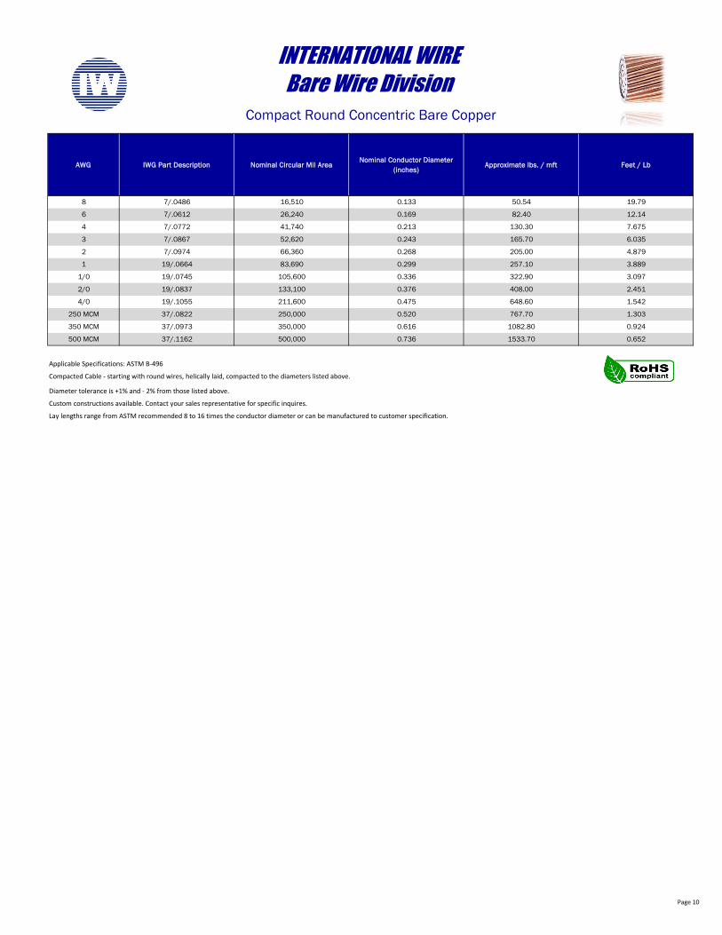
AWG IWG Part Description Nominal Circular Mil AreaNominal Conductor Diameter
(inches)Approximate lbs. / mft Feet / Lb
8 7/.0486 16,510 0.133 50.54 19.79
6 7/.0612 26,240 0.169 82.40 12.14
4 7/.0772 41,740 0.213 130.30 7.675
3 7/.0867 52,620 0.243 165.70 6.035
2 7/.0974 66,360 0.268 205.00 4.879
1 19/.0664 83,690 0.299 257.10 3.889
1/0 19/.0745 105,600 0.336 322.90 3.097
2/0 19/.0837 133,100 0.376 408.00 2.451
4/0 19/.1055 211,600 0.475 648.60 1.542
250 MCM 37/.0822 250,000 0.520 767.70 1.303
350 MCM 37/.0973 350,000 0.616 1082.80 0.924
500 MCM 37/.1162 500,000 0.736 1533.70 0.652
Diameter tolerance is +1% and - 2% from those listed above.
Custom constructions available. Contact your sales representative for specific inquires.
Lay lengths range from ASTM recommended 8 to 16 times the conductor diameter or can be manufactured to customer specification.
INTERNATIONAL WIREBare Wire Division
Compact Round Concentric Bare Copper
Applicable Specifications: ASTM B-496
Compacted Cable - starting with round wires, helically laid, compacted to the diameters listed above.
Page 11
AWG IWG Part Description Nominal Circular Mil AreaNominal Conductor Diameter
(inches)Approximate lbs. / mft Feet / Lb
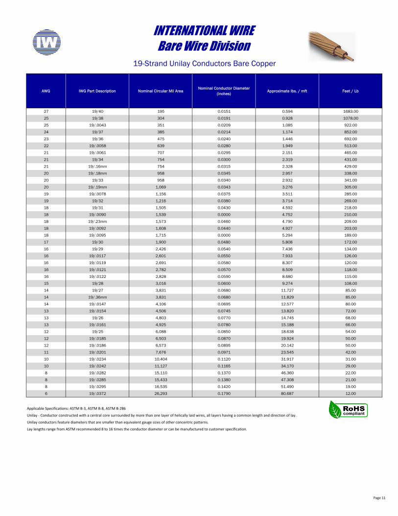
27 19/40 195 0.0151 0.594 1683.00
25 19/38 304 0.0191 0.928 1078.00
25 19/.0043 351 0.0209 1.085 922.00
24 19/37 385 0.0214 1.174 852.00
23 19/36 475 0.0240 1.446 692.00
22 19/.0058 639 0.0280 1.949 513.00
21 19/.0061 707 0.0295 2.151 465.00
21 19/34 754 0.0300 2.319 431.00
21 19/.16mm 754 0.0315 2.328 429.00
20 19/.18mm 958 0.0345 2.957 338.00
20 19/33 958 0.0340 2.932 341.00
20 19/.19mm 1,069 0.0343 3.276 305.00
19 19/.0078 1,156 0.0375 3.511 285.00
19 19/32 1,216 0.0380 3.714 269.00
18 19/31 1,505 0.0430 4.592 218.00
18 19/.0090 1,539 0.0000 4.752 210.00
18 19/.23mm 1,573 0.0460 4.790 209.00
18 19/.0092 1,608 0.0440 4.927 203.00
18 19/.0095 1,715 0.0000 5.294 189.00
17 19/30 1,900 0.0480 5.808 172.00
16 19/29 2,426 0.0540 7.436 134.00
16 19/.0117 2,601 0.0550 7.933 126.00
16 19/.0119 2,691 0.0580 8.307 120.00
16 19/.0121 2,782 0.0570 8.509 118.00
16 19/.0122 2,828 0.0590 8.680 115.00
15 19/28 3,016 0.0600 9.274 108.00
14 19/27 3,831 0.0680 11.727 85.00
14 19/.36mm 3,831 0.0680 11.829 85.00
14 19/.0147 4,106 0.0695 12.577 80.00
13 19/.0154 4,506 0.0745 13.820 72.00
13 19/26 4,803 0.0770 14.745 68.00
13 19/.0161 4,925 0.0780 15.188 66.00
12 19/25 6,088 0.0850 18.638 54.00
12 19/.0185 6,503 0.0870 19.924 50.00
12 19/.0186 6,573 0.0895 20.142 50.00
11 19/.0201 7,676 0.0971 23.545 42.00
10 19/.0234 10,404 0.1120 31.917 31.00
10 19/.0242 11,127 0.1165 34.170 29.00
8 19/.0282 15,110 0.1370 46.360 22.00
8 19/.0285 15,433 0.1380 47.308 21.00
8 19/.0295 16,535 0.1420 51.490 19.00
6 19/.0372 26,293 0.1790 80.687 12.00
Applicable Specifications: ASTM B-3, ASTM B-8, ASTM B-286
Unilay - Conductor constructed with a central core surrounded by more than one layer of helically laid wires, all layers having a common length and direction of lay.
Unilay conductors feature diameters that are smaller than equivalent gauge sizes of other concentric patterns.
Lay lengths range from ASTM recommended 8 to 16 times the conductor diameter or can be manufactured to customer specification.
INTERNATIONAL WIREBare Wire Division
19-Strand Unilay Conductors Bare Copper
Page 12
AWG IWG Part Description Nominal Circular Mil AreaNominal Conductor Diameter
(inches)Approximate lbs. / mft Feet / Lb
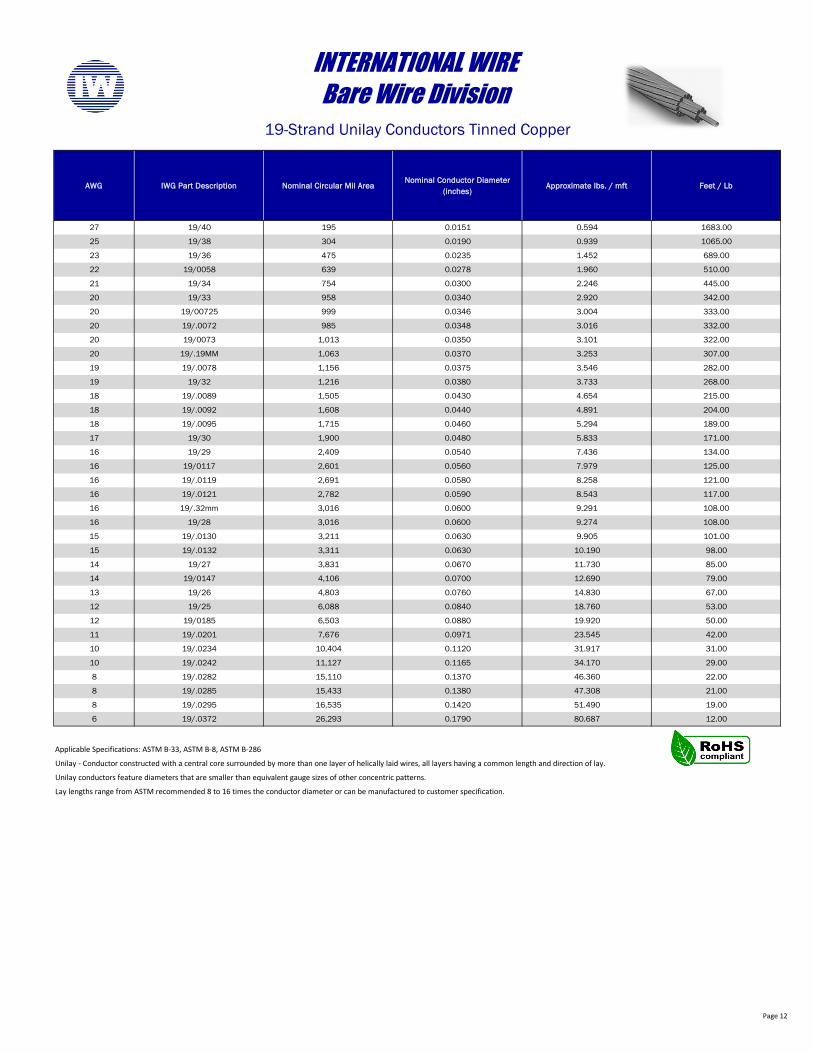
27 19/40 195 0.0151 0.594 1683.00
25 19/38 304 0.0190 0.939 1065.00
23 19/36 475 0.0235 1.452 689.00
22 19/0058 639 0.0278 1.960 510.00
21 19/34 754 0.0300 2.246 445.00
20 19/33 958 0.0340 2.920 342.00
20 19/00725 999 0.0346 3.004 333.00
20 19/.0072 985 0.0348 3.016 332.00
20 19/0073 1,013 0.0350 3.101 322.00
20 19/.19MM 1,063 0.0370 3.253 307.00
19 19/.0078 1,156 0.0375 3.546 282.00
19 19/32 1,216 0.0380 3.733 268.00
18 19/.0089 1,505 0.0430 4.654 215.00
18 19/.0092 1,608 0.0440 4.891 204.00
18 19/.0095 1,715 0.0460 5.294 189.00
17 19/30 1,900 0.0480 5.833 171.00
16 19/29 2,409 0.0540 7.436 134.00
16 19/0117 2,601 0.0560 7.979 125.00
16 19/.0119 2,691 0.0580 8.258 121.00
16 19/.0121 2,782 0.0590 8.543 117.00
16 19/.32mm 3,016 0.0600 9.291 108.00
16 19/28 3,016 0.0600 9.274 108.00
15 19/.0130 3,211 0.0630 9.905 101.00
15 19/.0132 3,311 0.0630 10.190 98.00
14 19/27 3,831 0.0670 11.730 85.00
14 19/0147 4,106 0.0700 12.690 79.00
13 19/26 4,803 0.0760 14.830 67.00
12 19/25 6,088 0.0840 18.760 53.00
12 19/0185 6,503 0.0880 19.920 50.00
11 19/.0201 7,676 0.0971 23.545 42.00
10 19/.0234 10,404 0.1120 31.917 31.00
10 19/.0242 11,127 0.1165 34.170 29.00
8 19/.0282 15,110 0.1370 46.360 22.00
8 19/.0285 15,433 0.1380 47.308 21.00
8 19/.0295 16,535 0.1420 51.490 19.00
6 19/.0372 26,293 0.1790 80.687 12.00
Applicable Specifications: ASTM B-33, ASTM B-8, ASTM B-286
Lay lengths range from ASTM recommended 8 to 16 times the conductor diameter or can be manufactured to customer specification.
INTERNATIONAL WIREBare Wire Division
19-Strand Unilay Conductors Tinned Copper
Unilay - Conductor constructed with a central core surrounded by more than one layer of helically laid wires, all layers having a common length and direction of lay.
Unilay conductors feature diameters that are smaller than equivalent gauge sizes of other concentric patterns.
Page 13
AWG IWG Part DescriptionNominal Conductor Diameter
(inches) Nominal Area In2 Approximate lbs. / mft Feet / Lb
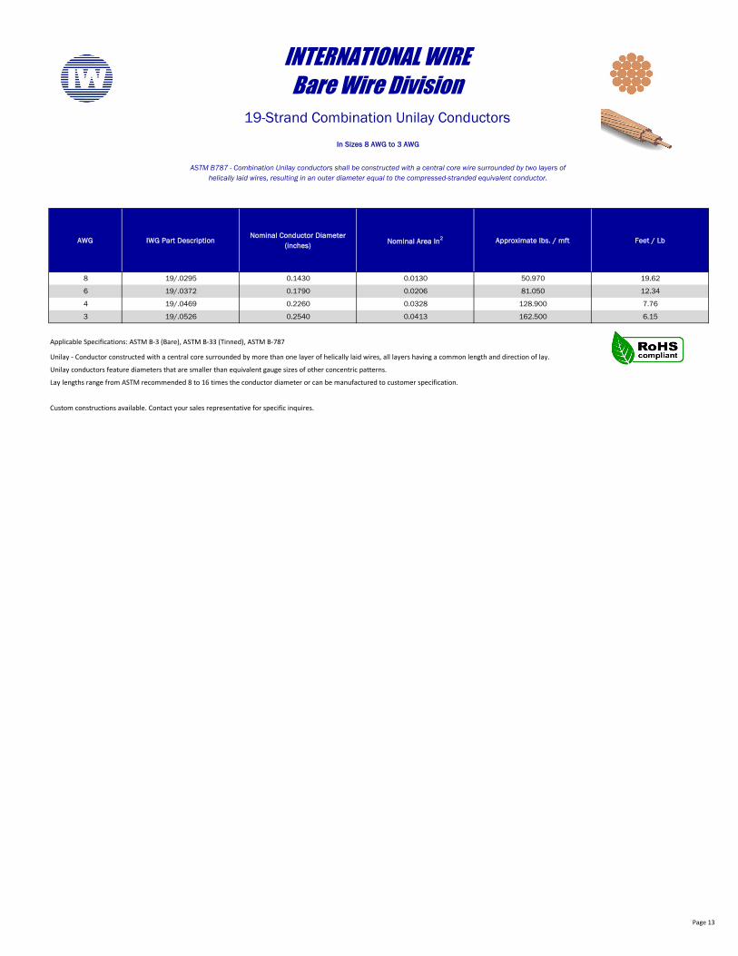
8 19/.0295 0.1430 0.0130 50.970 19.62
6 19/.0372 0.1790 0.0206 81.050 12.34
4 19/.0469 0.2260 0.0328 128.900 7.76
3 19/.0526 0.2540 0.0413 162.500 6.15
Custom constructions available. Contact your sales representative for specific inquires.
Lay lengths range from ASTM recommended 8 to 16 times the conductor diameter or can be manufactured to customer specification.
In Sizes 8 AWG to 3 AWG
ASTM B787 - Combination Unilay conductors shall be constructed with a central core wire surrounded by two layers of helically laid wires, resulting in an outer diameter equal to the compressed-stranded equivalent conductor.
Applicable Specifications: ASTM B-3 (Bare), ASTM B-33 (Tinned), ASTM B-787
INTERNATIONAL WIREBare Wire Division
19-Strand Combination Unilay Conductors
Unilay - Conductor constructed with a central core surrounded by more than one layer of helically laid wires, all layers having a common length and direction of lay.
Unilay conductors feature diameters that are smaller than equivalent gauge sizes of other concentric patterns.
Page 14
AWG IWG Part Description Nominal Circular Mil AreaNominal Conductor Diameter
(inches)Approximate lbs. / mft Feet / Lb
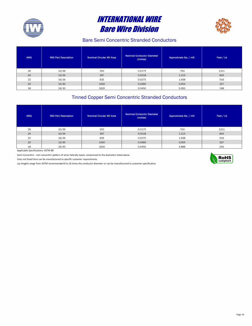
26 10/36 250 0.0175 .763 1311
24 10/34 397 0.0218 1.213 824
22 16/34 635 0.0275 1.938 516
20 10/30 1000 0.0360 3.054 327
18 16/30 1620 0.0450 5.063 198
AWG IWG Part Description Nominal Circular Mil AreaNominal Conductor Diameter
(inches)Approximate lbs. / mft Feet / Lb
26 10/36 250 0.0175 .763 1311
24 10/34 397 0.0218 1.213 824
22 16/34 635 0.0275 1.938 516
20 10/30 1000 0.0360 3.054 327
18 16/30 1620 0.0450 4.888 205
Semi-Concentric - non-concentric pattern of wires helically layed, compressed to the diameters listed above.
Lay lengths range from ASTM recommended 8 to 16 times the conductor diameter or can be manufactured to customer specification
INTERNATIONAL WIREBare Wire Division
Bare Semi Concentric Stranded Conductors
Applicable Specifications: ASTM B8
Sizes not listed here can be manufactured to specific customer requirements
Tinned Copper Semi Concentric Stranded Conductors
Page 15
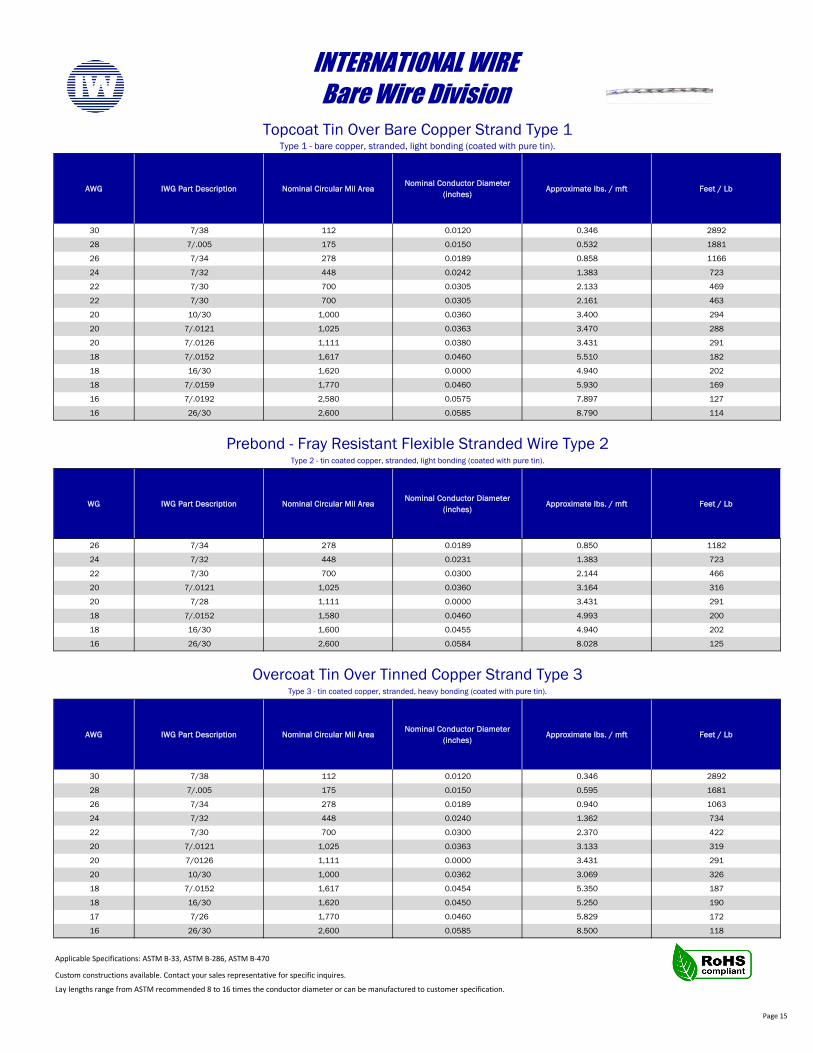
AWG IWG Part Description Nominal Circular Mil AreaNominal Conductor Diameter
(inches)Approximate lbs. / mft Feet / Lb
30 7/38 112 0.0120 0.346 2892
28 7/.005 175 0.0150 0.532 1881
26 7/34 278 0.0189 0.858 1166
24 7/32 448 0.0242 1.383 723
22 7/30 700 0.0305 2.133 469
22 7/30 700 0.0305 2.161 463
20 10/30 1,000 0.0360 3.400 294
20 7/.0121 1,025 0.0363 3.470 288
20 7/.0126 1,111 0.0380 3.431 291
18 7/.0152 1,617 0.0460 5.510 182
18 16/30 1,620 0.0000 4.940 202
18 7/.0159 1,770 0.0460 5.930 169
16 7/.0192 2,580 0.0575 7.897 127
16 26/30 2,600 0.0585 8.790 114
WG IWG Part Description Nominal Circular Mil AreaNominal Conductor Diameter
(inches)Approximate lbs. / mft Feet / Lb
26 7/34 278 0.0189 0.850 1182
24 7/32 448 0.0231 1.383 723
22 7/30 700 0.0300 2.144 466
20 7/.0121 1,025 0.0360 3.164 316
20 7/28 1,111 0.0000 3.431 291
18 7/.0152 1,580 0.0460 4.993 200
18 16/30 1,600 0.0455 4.940 202
16 26/30 2,600 0.0584 8.028 125
AWG IWG Part Description Nominal Circular Mil AreaNominal Conductor Diameter
(inches)Approximate lbs. / mft Feet / Lb
30 7/38 112 0.0120 0.346 2892
28 7/.005 175 0.0150 0.595 1681
26 7/34 278 0.0189 0.940 1063
24 7/32 448 0.0240 1.362 734
22 7/30 700 0.0300 2.370 422
20 7/.0121 1,025 0.0363 3.133 319
20 7/0126 1,111 0.0000 3.431 291
20 10/30 1,000 0.0362 3.069 326
18 7/.0152 1,617 0.0454 5.350 187
18 16/30 1,620 0.0450 5.250 190
17 7/26 1,770 0.0460 5.829 172
16 26/30 2,600 0.0585 8.500 118
Custom constructions available. Contact your sales representative for specific inquires.
Lay lengths range from ASTM recommended 8 to 16 times the conductor diameter or can be manufactured to customer specification.
Type 2 - tin coated copper, stranded, light bonding (coated with pure tin).
Type 1 - bare copper, stranded, light bonding (coated with pure tin).
Overcoat Tin Over Tinned Copper Strand Type 3Type 3 - tin coated copper, stranded, heavy bonding (coated with pure tin).
INTERNATIONAL WIREBare Wire Division
Topcoat Tin Over Bare Copper Strand Type 1
Prebond - Fray Resistant Flexible Stranded Wire Type 2
Applicable Specifications: ASTM B-33, ASTM B-286, ASTM B-470

Page 16
AWG IWG Part Description Nominal Circular Mil AreaNominal Conductor Diameter
(inches)Approximate lbs. / mft Feet / Lb
30 26/44 104 0.0117 .321 3114.3
29 33/44 132 0.0140 .408 2454.0
28 41/44 164 0.0150 .506 1975.1
27 19/40 195 0.0160 .601 1664.7
26 65/44 260 0.0180 .803 1245.8
25 30/40 307 0.0201 .939 1065.4
24 16/36 400 0.0240 1.235 809.7
24 27/38 432 0.0245 1.401 713.6
24 40/40 410 0.0230 1.265 790.8
24 41/40 420 0.0236 1.296 771.5
24 105/44 420 0.0235 1.297 771.2
22 16/34 635 0.0289 1.961 510.0
22 26/36 650 0.0310 2.007 498.3
22 41/38 656 0.0000 2.025 493.7
22 61/40 625 0.0285 1.929 518.5
22 65/40 666 0.0300 2.055 486.6
21 19/.16mm 754 0.0315 2.292 436.4
21 22/34 873 0.0330 2.696 370.9
20 7/.31mm 1042 0.0360 3.157 316.7
20 7/.0124 1076 0.0376 3.323 300.9
20 7/.0126 1111 0.0380 3.370 296.8
20 7/.32mm 1111 0.0378 3.373 296.5
20 10/30 1000 0.0380 3.088 323.9
20 12/31 951 0.0350 2.935 340.8
20 16/32 1024 0.0365 3.110 321.6
20 19/.18mm 958 0.0350 2.907 344.0
20 19/.19mm 1069 0.0365 3.159 316.5
20 20/.18mm 1008 0.0360 3.026 330.5
20 26/34 1032 0.0360 3.186 313.9
20 41/36 1025 0.0368 3.165 316.0
20 105/40 1075 0.0364 3.320 301.2
19 19/.22mm 1438 0.0430 4.339 230.5
19 56/36 1400 0.0430 4.323 231.3
19 74/38 1184 0.0380 3.656 273.6
19 133/40 1362 0.0424 4.141 241.5
18 7/.378mm 1554 0.0447 4.709 212.4
18 16/.26mm 1665 0.0460 4.744 210.8
18 16/.0098 1537 0.0460 4.744 210.8
18 16/30 1600 0.0480 4.868 205.4
18 19/.23mm 1573 0.0460 4.777 209.3
18 19/.0092 1608 0.0460 4.777 209.3
18 20/31 1584 0.0460 4.891 204.4
18 24/.0079 1498 0.0450 4.625 216.2
18 24/32 1536 0.0450 4.665 214.4
18 30/.0071 1512 0.0450 4.669 214.2
18 30/.18mm 1512 0.0473 4.669 214.2
18 41/34 1627 0.0460 5.024 199.0
18 65/36 1625 0.0460 5.017 199.3
18 114/38 1824 0.0490 5.632 177.6
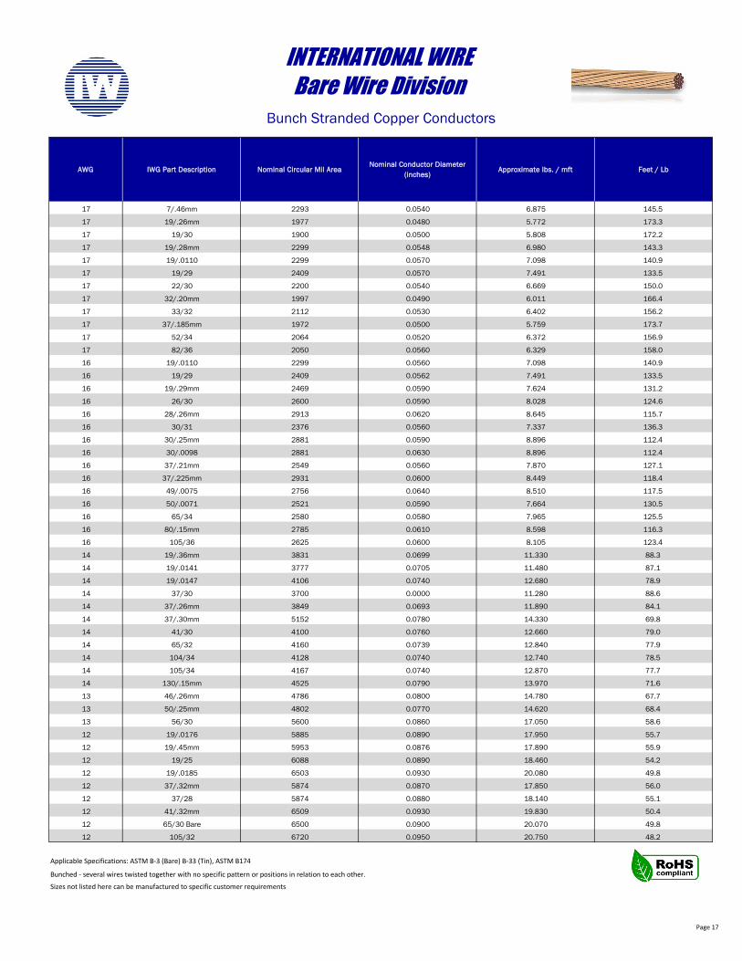
Bunched - several wires twisted together with no specific pattern or positions in relation to each other.
Applicable Specifications: ASTM B-3 (Bare) B-33 (Tin), ASTM B174
Sizes not listed here can be manufactured to specific customer requirements
INTERNATIONAL WIREBare Wire Division
Bunch Stranded Copper Conductors
Bunch Strand Continued on next page…
Page 17
AWG IWG Part Description Nominal Circular Mil AreaNominal Conductor Diameter
(inches)Approximate lbs. / mft Feet / Lb
17 7/.46mm 2293 0.0540 6.875 145.5
17 19/.26mm 1977 0.0480 5.772 173.3
17 19/30 1900 0.0500 5.808 172.2
17 19/.28mm 2299 0.0548 6.980 143.3
17 19/.0110 2299 0.0570 7.098 140.9
17 19/29 2409 0.0570 7.491 133.5
17 22/30 2200 0.0540 6.669 150.0
17 32/.20mm 1997 0.0490 6.011 166.4
17 33/32 2112 0.0530 6.402 156.2
17 37/.185mm 1972 0.0500 5.759 173.7
17 52/34 2064 0.0520 6.372 156.9
17 82/36 2050 0.0560 6.329 158.0
16 19/.0110 2299 0.0560 7.098 140.9
16 19/29 2409 0.0562 7.491 133.5
16 19/.29mm 2469 0.0590 7.624 131.2
16 26/30 2600 0.0590 8.028 124.6
16 28/.26mm 2913 0.0620 8.645 115.7
16 30/31 2376 0.0560 7.337 136.3
16 30/.25mm 2881 0.0590 8.896 112.4
16 30/.0098 2881 0.0630 8.896 112.4
16 37/.21mm 2549 0.0560 7.870 127.1
16 37/.225mm 2931 0.0600 8.449 118.4
16 49/.0075 2756 0.0640 8.510 117.5
16 50/.0071 2521 0.0590 7.664 130.5
16 65/34 2580 0.0580 7.965 125.5
16 80/.15mm 2785 0.0610 8.598 116.3
16 105/36 2625 0.0600 8.105 123.4
14 19/.36mm 3831 0.0699 11.330 88.3
14 19/.0141 3777 0.0705 11.480 87.1
14 19/.0147 4106 0.0740 12.680 78.9
14 37/30 3700 0.0000 11.280 88.6
14 37/.26mm 3849 0.0693 11.890 84.1
14 37/.30mm 5152 0.0780 14.330 69.8
14 41/30 4100 0.0760 12.660 79.0
14 65/32 4160 0.0739 12.840 77.9
14 104/34 4128 0.0740 12.740 78.5
14 105/34 4167 0.0740 12.870 77.7
14 130/.15mm 4525 0.0790 13.970 71.6
13 46/.26mm 4786 0.0800 14.780 67.7
13 50/.25mm 4802 0.0770 14.620 68.4
13 56/30 5600 0.0860 17.050 58.6
12 19/.0176 5885 0.0890 17.950 55.7
12 19/.45mm 5953 0.0876 17.890 55.9
12 19/25 6088 0.0890 18.460 54.2
12 19/.0185 6503 0.0930 20.080 49.8
12 37/.32mm 5874 0.0870 17.850 56.0
12 37/28 5874 0.0880 18.140 55.1
12 41/.32mm 6509 0.0930 19.830 50.4
12 65/30 Bare 6500 0.0900 20.070 49.8
12 105/32 6720 0.0950 20.750 48.2
Bunched - several wires twisted together with no specific pattern or positions in relation to each other.
Applicable Specifications: ASTM B-3 (Bare) B-33 (Tin), ASTM B174
Sizes not listed here can be manufactured to specific customer requirements
INTERNATIONAL WIREBare Wire Division
Bunch Stranded Copper Conductors
Page 18
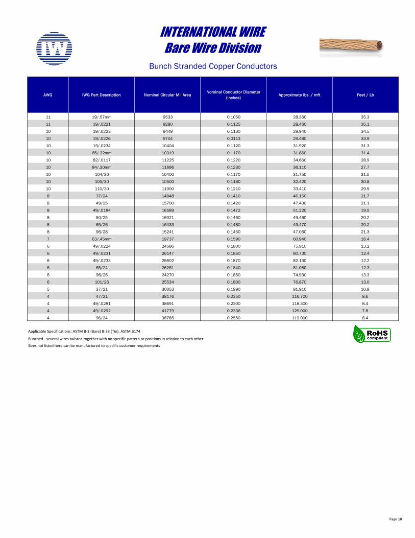
AWG IWG Part Description Nominal Circular Mil AreaNominal Conductor Diameter
(inches)Approximate lbs. / mft Feet / Lb
11 19/.57mm 9533 0.1050 28.360 35.3
11 19/.0221 9280 0.1125 28.460 35.1
10 19/.0223 9449 0.1130 28.940 34.5
10 19/.0226 9704 0.0113 29.480 33.9
10 19/.0234 10404 0.1120 31.920 31.3
10 65/.32mm 10319 0.1170 31.860 31.4
10 82/.0117 11225 0.1220 34.660 28.9
10 84/.30mm 11696 0.1230 36.110 27.7
10 104/30 10400 0.1170 31.750 31.5
10 105/30 10500 0.1180 32.420 30.8
10 110/30 11000 0.1210 33.410 29.9
8 37/24 14948 0.1410 46.150 21.7
8 49/25 15700 0.1420 47.400 21.1
8 49/.0184 16589 0.1472 51.220 19.5
8 50/25 16021 0.1460 49.460 20.2
8 65/26 16433 0.1480 49.470 20.2
8 96/28 15241 0.1450 47.060 21.3
7 63/.45mm 19737 0.1590 60.940 16.4
6 49/.0224 24586 0.1800 75.910 13.2
6 49/.0231 26147 0.1850 80.730 12.4
6 49/.0233 26602 0.1870 82.130 12.2
6 65/24 26261 0.1840 81.080 12.3
6 96/26 24270 0.1850 74.930 13.3
6 101/26 25534 0.1800 76.870 13.0
5 37/21 30053 0.1990 91.910 10.9
4 47/21 38176 0.2350 116.700 8.6
4 49/.0281 38691 0.2300 118.300 8.4
4 49/.0292 41779 0.2336 129.000 7.8
4 96/24 38785 0.2550 119.000 8.4
Bunched - several wires twisted together with no specific pattern or positions in relation to each other.
INTERNATIONAL WIREBare Wire Division
Bunch Stranded Copper Conductors
Applicable Specifications: ASTM B-3 (Bare) B-33 (Tin), ASTM B174
Sizes not listed here can be manufactured to specific customer requirements
Page 19
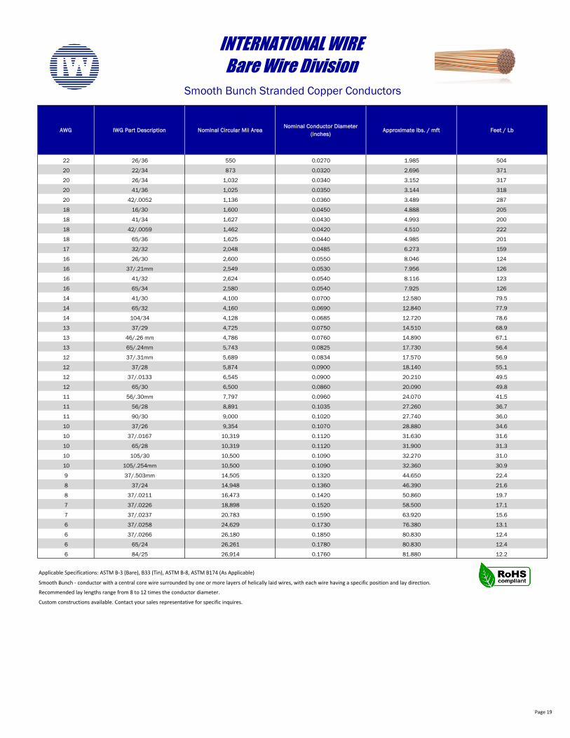
AWG IWG Part Description Nominal Circular Mil AreaNominal Conductor Diameter
(inches)Approximate lbs. / mft Feet / Lb
22 26/36 550 0.0270 1.985 504
20 22/34 873 0.0320 2.696 371
20 26/34 1,032 0.0340 3.152 317
20 41/36 1,025 0.0350 3.144 318
20 42/.0052 1,136 0.0360 3.489 287
18 16/30 1,600 0.0450 4.888 205
18 41/34 1,627 0.0430 4.993 200
18 42/.0059 1,462 0.0420 4.510 222
18 65/36 1,625 0.0440 4.985 201
17 32/32 2,048 0.0485 6.273 159
16 26/30 2,600 0.0550 8.046 124
16 37/.21mm 2,549 0.0530 7.956 126
16 41/32 2,624 0.0540 8.116 123
16 65/34 2,580 0.0540 7.925 126
14 41/30 4,100 0.0700 12.580 79.5
14 65/32 4,160 0.0690 12.840 77.9
14 104/34 4,128 0.0685 12.720 78.6
13 37/29 4,725 0.0750 14.510 68.9
13 46/.26 mm 4,786 0.0760 14.890 67.1
13 65/.24mm 5,743 0.0825 17.730 56.4
12 37/.31mm 5,689 0.0834 17.570 56.9
12 37/28 5,874 0.0900 18.140 55.1
12 37/.0133 6,545 0.0900 20.210 49.5
12 65/30 6,500 0.0860 20.090 49.8
11 56/.30mm 7,797 0.0960 24.070 41.5
11 56/28 8,891 0.1035 27.260 36.7
11 90/30 9,000 0.1020 27.740 36.0
10 37/26 9,354 0.1070 28.880 34.6
10 37/.0167 10,319 0.1120 31.630 31.6
10 65/28 10,319 0.1120 31.900 31.3
10 105/30 10,500 0.1090 32.270 31.0
10 105/.254mm 10,500 0.1090 32.360 30.9
9 37/.503mm 14,505 0.1320 44.650 22.4
8 37/24 14,948 0.1360 46.390 21.6
8 37/.0211 16,473 0.1420 50.860 19.7
7 37/.0226 18,898 0.1520 58.500 17.1
7 37/.0237 20,783 0.1590 63.920 15.6
6 37/.0258 24,629 0.1730 76.380 13.1
6 37/.0266 26,180 0.1850 80.830 12.4
6 65/24 26,261 0.1780 80.830 12.4
6 84/25 26,914 0.1760 81.880 12.2
Smooth Bunch - conductor with a central core wire surrounded by one or more layers of helically laid wires, with each wire having a specific position and lay direction.
Recommended lay lengths range from 8 to 12 times the conductor diameter.
Custom constructions available. Contact your sales representative for specific inquires.
INTERNATIONAL WIREBare Wire Division
Smooth Bunch Stranded Copper Conductors
Applicable Specifications: ASTM B-3 (Bare), B33 (Tin), ASTM B-8, ASTM B174 (As Applicable)
Page 20
AWG IWG Part Description Nominal Circular Mil AreaNominal Conductor Diameter
(inches)Approximate lbs. / mft Feet / Lb
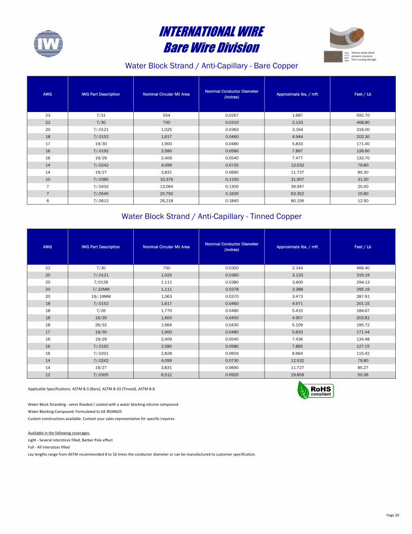
23 7/31 554 0.0267 1.687 592.70
22 7/30 700 0.0310 2.133 468.80
20 7/.0121 1,025 0.0363 3.164 316.00
18 7/.0152 1,617 0.0460 4.944 202.30
17 19/30 1,900 0.0480 5.833 171.40
16 7/.0192 2,580 0.0580 7.897 126.60
16 19/29 2,409 0.0540 7.477 133.70
14 7/.0242 4,099 0.0725 12.532 79.80
14 19/27 3,831 0.0690 11.727 85.30
10 7/.0385 10,376 0.1150 31.907 31.30
7 7/.0432 13,064 0.1300 39.947 25.00
7 7/.0545 20,792 0.1630 63.352 15.80
6 7/.0612 26,218 0.1840 80.156 12.50
AWG IWG Part Description Nominal Circular Mil AreaNominal Conductor Diameter
(inches)Approximate lbs. / mft Feet / Lb
22 7/30 700 0.0300 2.144 466.40
20 7/.0121 1,025 0.0360 3.133 319.19
20 7/0126 1,111 0.0380 3.400 294.13
20 7/.32MM 1,111 0.0378 3.388 295.19
20 19/.19MM 1,063 0.0370 3.473 287.91
18 7/.0152 1,617 0.0460 4.971 201.15
18 7/26 1,770 0.0480 5.415 184.67
18 16/30 1,600 0.0450 4.907 203.81
18 26/32 1,664 0.0430 5.109 195.72
17 19/30 1,900 0.0480 5.833 171.44
16 19/29 2,409 0.0540 7.436 134.48
16 7/.0192 2,580 0.0580 7.865 127.15
16 7/.0201 2,828 0.0603 8.664 115.42
14 7/.0242 4,099 0.0730 12.532 79.80
14 19/27 3,831 0.0690 11.727 85.27
12 7/.0305 6,512 0.0920 19.859 50.36
Water Block Stranding - wires flooded / coated with a water blocking silicone compound.
Water Blocking Compound: Formulated to GE 9034N25
Custom constructions available. Contact your sales representative for specific inquires.
Available in the following coverages:
Light - Several interstices filled, Barber Pole effect
Full - All interstices filled
Lay lengths range from ASTM recommended 8 to 16 times the conductor diameter or can be manufactured to customer specification.
Water Block Strand / Anti-Capillary - Tinned Copper
INTERNATIONAL WIREBare Wire Division
Water Block Strand / Anti-Capillary - Bare Copper
Applicable Specifications: ASTM B-3 (Bare), ASTM B-33 (Tinned), ASTM B-8
Silicone water-block prevents moisture from causing damage.
Page 21
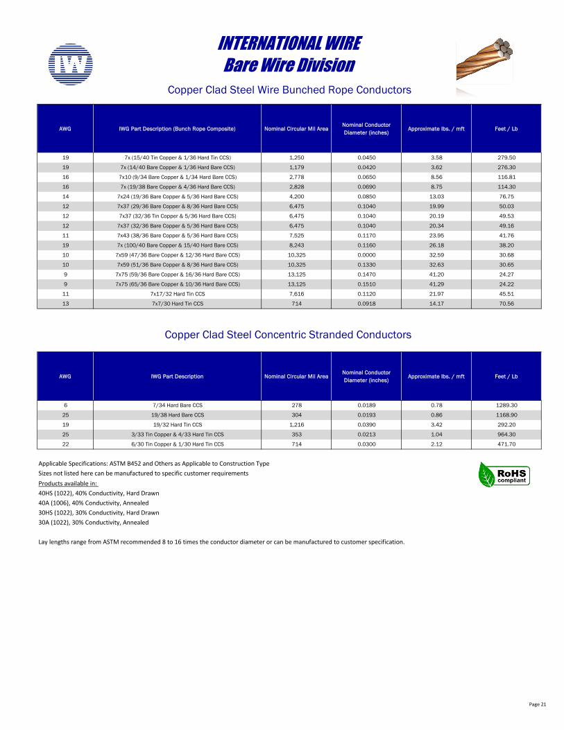
AWG IWG Part Description (Bunch Rope Composite) Nominal Circular Mil AreaNominal Conductor Diameter (inches)
Approximate lbs. / mft Feet / Lb
19 7x (15/40 Tin Copper & 1/36 Hard Tin CCS) 1,250 0.0450 3.58 279.50
19 7x (14/40 Bare Copper & 1/36 Hard Bare CCS) 1,179 0.0420 3.62 276.30
16 7x10 (9/34 Bare Copper & 1/34 Hard Bare CCS) 2,778 0.0650 8.56 116.81
16 7x (19/38 Bare Copper & 4/36 Hard Bare CCS) 2,828 0.0690 8.75 114.30
14 7x24 (19/36 Bare Copper & 5/36 Hard Bare CCS) 4,200 0.0850 13.03 76.75
12 7x37 (29/36 Bare Copper & 8/36 Hard Bare CCS) 6,475 0.1040 19.99 50.03
12 7x37 (32/36 Tin Copper & 5/36 Hard Bare CCS) 6,475 0.1040 20.19 49.53
12 7x37 (32/36 Bare Copper & 5/36 Hard Bare CCS) 6,475 0.1040 20.34 49.16
11 7x43 (38/36 Bare Copper & 5/36 Hard Bare CCS) 7,525 0.1170 23.95 41.76
19 7x (100/40 Bare Copper & 15/40 Hard Bare CCS) 8,243 0.1160 26.18 38.20
10 7x59 (47/36 Bare Copper & 12/36 Hard Bare CCS) 10,325 0.0000 32.59 30.68
10 7x59 (51/36 Bare Copper & 8/36 Hard Bare CCS) 10,325 0.1330 32.63 30.65
9 7x75 (59/36 Bare Copper & 16/36 Hard Bare CCS) 13,125 0.1470 41.20 24.27
9 7x75 (65/36 Bare Copper & 10/36 Hard Bare CCS) 13,125 0.1510 41.29 24.22
11 7x17/32 Hard Tin CCS 7,616 0.1120 21.97 45.51
13 7x7/30 Hard Tin CCS 714 0.0918 14.17 70.56
AWG IWG Part Description Nominal Circular Mil AreaNominal Conductor Diameter (inches)
Approximate lbs. / mft Feet / Lb
6 7/34 Hard Bare CCS 278 0.0189 0.78 1289.30
25 19/38 Hard Bare CCS 304 0.0193 0.86 1168.90
19 19/32 Hard Tin CCS 1,216 0.0390 3.42 292.20
25 3/33 Tin Copper & 4/33 Hard Tin CCS 353 0.0213 1.04 964.30
22 6/30 Tin Copper & 1/30 Hard Tin CCS 714 0.0300 2.12 471.70
Products available in: 40HS (1022), 40% Conductivity, Hard Drawn40A (1006), 40% Conductivity, Annealed30HS (1022), 30% Conductivity, Hard Drawn30A (1022), 30% Conductivity, Annealed
Lay lengths range from ASTM recommended 8 to 16 times the conductor diameter or can be manufactured to customer specification.
Applicable Specifications: ASTM B452 and Others as Applicable to Construction TypeSizes not listed here can be manufactured to specific customer requirements
INTERNATIONAL WIREBare Wire Division
Copper Clad Steel Wire Bunched Rope Conductors
Copper Clad Steel Concentric Stranded Conductors
Page 22
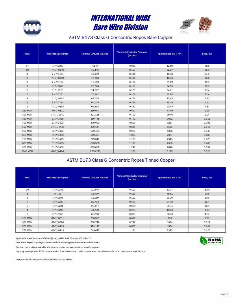
AWG IWG Part Description Nominal Circular Mil AreaNominal Conductor Diameter
(inches)Approximate lbs. / mft Feet / Lb
14 7x7/.0092 4,147 0.080 12.69 78.8
10 7 x 7/.0146 10,445 0.127 32.37 30.9
9 7 x 7/0164 13,179 0.146 40.78 24.5
8 7 x 7/.0179 15,700 0.160 48.46 20.6
8 7 x 7/0184 16,589 0.162 51.29 19.5
7 7x7/.0206 20,794 0.183 64.55 15.5
6 7x7/.0223 24,367 0.201 74.81 13.4
6 7 x 7/0231 26,147 0.208 80.89 12.4
4 7 x 7/.0292 41,779 0.255 129.3 7.73
2 7 x 7/0350 60,025 0.315 191.8 5.21
2 7 x 7/.0368 66,358 0.331 205.3 4.87
250 MCM 37x7/.0311 250,507 0.627 774.9 1.29
300 MCM 37 x 7/0340 301,168 0.700 960.0 1.04
350 MCM 37x7/0368 350,748 0.742 1092 0.915
400 MCM 37x7/0393 400,023 0.800 1257 0.796
500 MCM 37 x 7/0439 499,147 0.885 1555 0.643
600 MCM 61x7/0375 600,469 0.995 1876 0.533
650 MCM 61x7/0390 649,467 1.025 2057 0.486
750 MCM 61x7/0419 749,645 1.131 2345 0.426
800 MCM 61x7/0433 800,578 1.170 2500 0.400
900 MCM 61x7/0459 899,608 1.240 2848 0.351
1000 MCM 61x7/.0484 1,000,273 1.260 3125 0.320
AWG IWG Part Description Nominal Circular Mil AreaNominal Conductor Diameter
(inches)Approximate lbs. / mft Feet / Lb
10 7x7/.0146 10,445 0.127 32.37 30.9
8 7x7/25 15,700 0.153 48.51 20.6
8 7x7/.0184 16,589 0.162 51.29 19.5
7 7x7/.0206 20,794 0.183 64.78 15.4
6 7x7/.0231 26,147 0.208 80.75 12.4
4 7x7/.0292 41,779 0.255 129.3 7.73
2 7x7/.0368 66,358 0.331 205.3 4.87
250 MCM 37x7/.0311 250,507 0.627 776 1.29
350 MCM 37x7/.0368 350,748 0.742 1094 0.914
500 MCM 37x7/.0439 499,147 0.885 1554 0.644
750 MCM 61x7/.0419 749,645 1.131 2383 0.420
Custom constructions available. Contact your sales representative for specific inquires.
Lay lengths range from ASTM recommended 8 to 16 times the conductor diameter or can be manufactured to customer specification.
Compressed versions available for all constructions above.
Concentric Ropes: rope-lay-stranded conductors having concentric-stranded members.
INTERNATIONAL WIREBare Wire Division
ASTM B173 Class G Concentric Ropes Bare Copper
ASTM B173 Class G Concentric Ropes Tinned Copper
Applicable Specifications: ASTM B-3 (Bare), ASTM B-33 (Tinned), ASTM B-173
Page 23
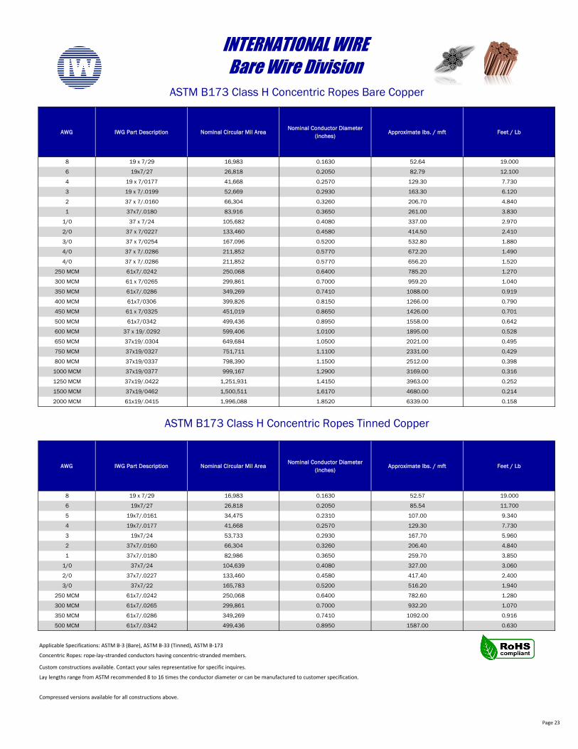
AWG IWG Part Description Nominal Circular Mil AreaNominal Conductor Diameter
(inches)Approximate lbs. / mft Feet / Lb
8 19 x 7/29 16,983 0.1630 52.64 19.000
6 19x7/27 26,818 0.2050 82.79 12.100
4 19 x 7/0177 41,668 0.2570 129.30 7.730
3 19 x 7/.0199 52,669 0.2930 163.30 6.120
2 37 x 7/.0160 66,304 0.3260 206.70 4.840
1 37x7/.0180 83,916 0.3650 261.00 3.830
1/0 37 x 7/24 105,682 0.4080 337.00 2.970
2/0 37 x 7/0227 133,460 0.4580 414.50 2.410
3/0 37 x 7/0254 167,096 0.5200 532.80 1.880
4/0 37 x 7/.0286 211,852 0.5770 672.20 1.490
4/0 37 x 7/.0286 211,852 0.5770 656.20 1.520
250 MCM 61x7/.0242 250,068 0.6400 785.20 1.270
300 MCM 61 x 7/0265 299,861 0.7000 959.20 1.040
350 MCM 61x7/.0286 349,269 0.7410 1088.00 0.919
400 MCM 61x7/0306 399,826 0.8150 1266.00 0.790
450 MCM 61 x 7/0325 451,019 0.8650 1426.00 0.701
500 MCM 61x7/0342 499,436 0.8950 1558.00 0.642
600 MCM 37 x 19/.0292 599,406 1.0100 1895.00 0.528
650 MCM 37x19/.0304 649,684 1.0500 2021.00 0.495
750 MCM 37x19/0327 751,711 1.1100 2331.00 0.429
800 MCM 37x19/0337 798,390 1.1500 2512.00 0.398
1000 MCM 37x19/0377 999,167 1.2900 3169.00 0.316
1250 MCM 37x19/.0422 1,251,931 1.4150 3963.00 0.252
1500 MCM 37x19/0462 1,500,511 1.6170 4680.00 0.214
2000 MCM 61x19/.0415 1,996,088 1.8520 6339.00 0.158
AWG IWG Part Description Nominal Circular Mil AreaNominal Conductor Diameter
(inches)Approximate lbs. / mft Feet / Lb
8 19 x 7/29 16,983 0.1630 52.57 19.000
6 19x7/27 26,818 0.2050 85.54 11.700
5 19x7/.0161 34,475 0.2310 107.00 9.340
4 19x7/.0177 41,668 0.2570 129.30 7.730
3 19x7/24 53,733 0.2930 167.70 5.960
2 37x7/.0160 66,304 0.3260 206.40 4.840
1 37x7/.0180 82,986 0.3650 259.70 3.850
1/0 37x7/24 104,639 0.4080 327.00 3.060
2/0 37x7/.0227 133,460 0.4580 417.40 2.400
3/0 37x7/22 165,783 0.5200 516.20 1.940
250 MCM 61x7/.0242 250,068 0.6400 782.60 1.280
300 MCM 61x7/.0265 299,861 0.7000 932.20 1.070
350 MCM 61x7/.0286 349,269 0.7410 1092.00 0.916
500 MCM 61x7/.0342 499,436 0.8950 1587.00 0.630
Custom constructions available. Contact your sales representative for specific inquires.
Lay lengths range from ASTM recommended 8 to 16 times the conductor diameter or can be manufactured to customer specification.
Compressed versions available for all constructions above.
Applicable Specifications: ASTM B-3 (Bare), ASTM B-33 (Tinned), ASTM B-173
Concentric Ropes: rope-lay-stranded conductors having concentric-stranded members.
INTERNATIONAL WIREBare Wire Division
ASTM B173 Class H Concentric Ropes Bare Copper
ASTM B173 Class H Concentric Ropes Tinned Copper
Page 24
AWG IWG Part Description Nominal Circular Mil AreaNominal Conductor Diameter
(inches)Approximate lbs. / mft Feet / Lb
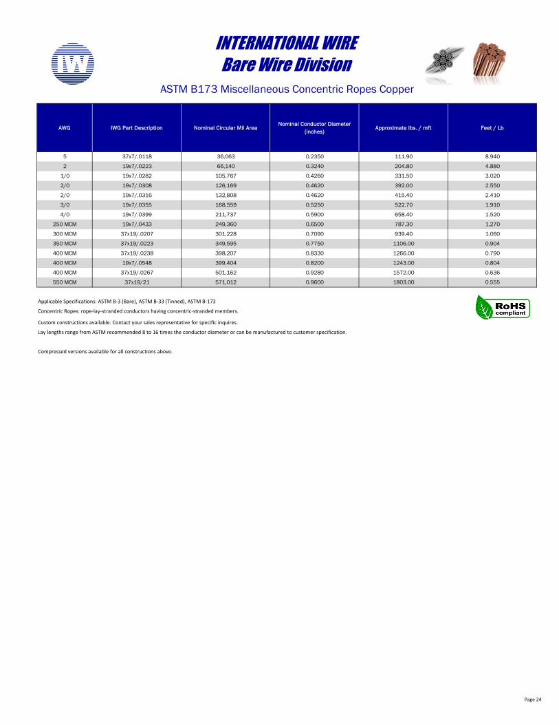
5 37x7/.0118 36,063 0.2350 111.90 8.940
2 19x7/.0223 66,140 0.3240 204.80 4.880
1/0 19x7/.0282 105,767 0.4260 331.50 3.020
2/0 19x7/.0308 126,169 0.4620 392.00 2.550
2/0 19x7/.0316 132,808 0.4620 415.40 2.410
3/0 19x7/.0355 168,559 0.5250 522.70 1.910
4/0 19x7/.0399 211,737 0.5900 658.40 1.520
250 MCM 19x7/.0433 249,360 0.6500 787.30 1.270
300 MCM 37x19/.0207 301,228 0.7090 939.40 1.060
350 MCM 37x19/.0223 349,595 0.7750 1106.00 0.904
400 MCM 37x19/.0238 398,207 0.8330 1266.00 0.790
400 MCM 19x7/.0548 399,404 0.8200 1243.00 0.804
400 MCM 37x19/.0267 501,162 0.9280 1572.00 0.636
550 MCM 37x19/21 571,012 0.9600 1803.00 0.555
Custom constructions available. Contact your sales representative for specific inquires.
Lay lengths range from ASTM recommended 8 to 16 times the conductor diameter or can be manufactured to customer specification.
Compressed versions available for all constructions above.
INTERNATIONAL WIREBare Wire Division
ASTM B173 Miscellaneous Concentric Ropes Copper
Applicable Specifications: ASTM B-3 (Bare), ASTM B-33 (Tinned), ASTM B-173
Concentric Ropes: rope-lay-stranded conductors having concentric-stranded members.
Page 25
AWG IWG Part Description Nominal Circular Mil AreaNominal Conductor Diameter
(inches)Approximate lbs. / mft Feet / Lb
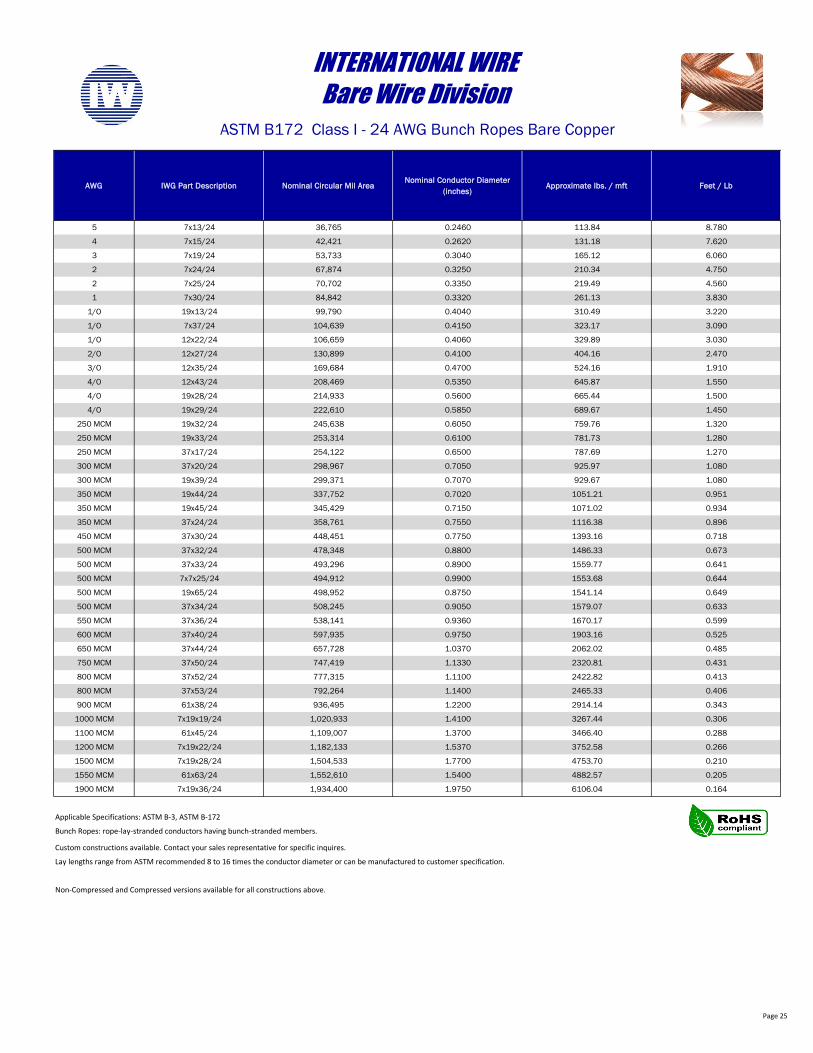
5 7x13/24 36,765 0.2460 113.84 8.780
4 7x15/24 42,421 0.2620 131.18 7.620
3 7x19/24 53,733 0.3040 165.12 6.060
2 7x24/24 67,874 0.3250 210.34 4.750
2 7x25/24 70,702 0.3350 219.49 4.560
1 7x30/24 84,842 0.3320 261.13 3.830
1/O 19x13/24 99,790 0.4040 310.49 3.220
1/O 7x37/24 104,639 0.4150 323.17 3.090
1/O 12x22/24 106,659 0.4060 329.89 3.030
2/O 12x27/24 130,899 0.4100 404.16 2.470
3/O 12x35/24 169,684 0.4700 524.16 1.910
4/O 12x43/24 208,469 0.5350 645.87 1.550
4/O 19x28/24 214,933 0.5600 665.44 1.500
4/O 19x29/24 222,610 0.5850 689.67 1.450
250 MCM 19x32/24 245,638 0.6050 759.76 1.320
250 MCM 19x33/24 253,314 0.6100 781.73 1.280
250 MCM 37x17/24 254,122 0.6500 787.69 1.270
300 MCM 37x20/24 298,967 0.7050 925.97 1.080
300 MCM 19x39/24 299,371 0.7070 929.67 1.080
350 MCM 19x44/24 337,752 0.7020 1051.21 0.951
350 MCM 19x45/24 345,429 0.7150 1071.02 0.934
350 MCM 37x24/24 358,761 0.7550 1116.38 0.896
450 MCM 37x30/24 448,451 0.7750 1393.16 0.718
500 MCM 37x32/24 478,348 0.8800 1486.33 0.673
500 MCM 37x33/24 493,296 0.8900 1559.77 0.641
500 MCM 7x7x25/24 494,912 0.9900 1553.68 0.644
500 MCM 19x65/24 498,952 0.8750 1541.14 0.649
500 MCM 37x34/24 508,245 0.9050 1579.07 0.633
550 MCM 37x36/24 538,141 0.9360 1670.17 0.599
600 MCM 37x40/24 597,935 0.9750 1903.16 0.525
650 MCM 37x44/24 657,728 1.0370 2062.02 0.485
750 MCM 37x50/24 747,419 1.1330 2320.81 0.431
800 MCM 37x52/24 777,315 1.1100 2422.82 0.413
800 MCM 37x53/24 792,264 1.1400 2465.33 0.406
900 MCM 61x38/24 936,495 1.2200 2914.14 0.343
1000 MCM 7x19x19/24 1,020,933 1.4100 3267.44 0.306
1100 MCM 61x45/24 1,109,007 1.3700 3466.40 0.288
1200 MCM 7x19x22/24 1,182,133 1.5370 3752.58 0.266
1500 MCM 7x19x28/24 1,504,533 1.7700 4753.70 0.210
1550 MCM 61x63/24 1,552,610 1.5400 4882.57 0.205
1900 MCM 7x19x36/24 1,934,400 1.9750 6106.04 0.164
Custom constructions available. Contact your sales representative for specific inquires.
Lay lengths range from ASTM recommended 8 to 16 times the conductor diameter or can be manufactured to customer specification.
Non-Compressed and Compressed versions available for all constructions above.
INTERNATIONAL WIREBare Wire Division
ASTM B172 Class I - 24 AWG Bunch Ropes Bare Copper
Applicable Specifications: ASTM B-3, ASTM B-172
Bunch Ropes: rope-lay-stranded conductors having bunch-stranded members.
Page 26
AWG IWG Part Description Nominal Circular Mil AreaNominal Conductor Diameter
(inches)Approximate lbs. / mft Feet / Lb
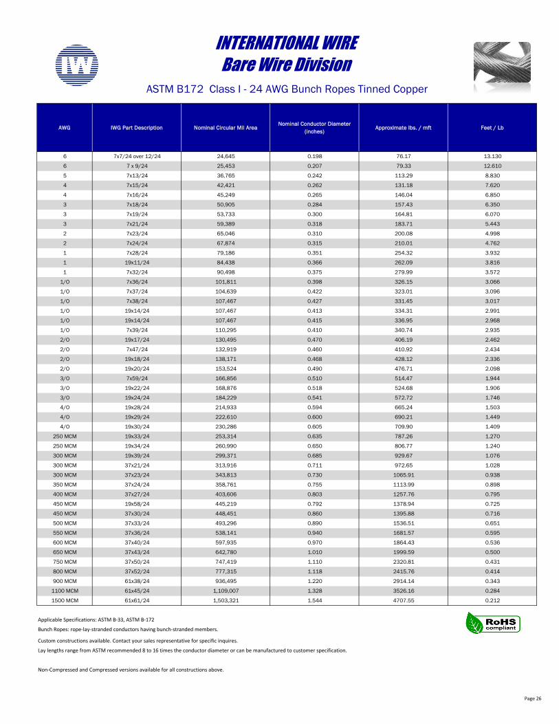
6 7x7/24 over 12/24 24,645 0.198 76.17 13.130
6 7 x 9/24 25,453 0.207 79.33 12.610
5 7x13/24 36,765 0.242 113.29 8.830
4 7x15/24 42,421 0.262 131.18 7.620
4 7x16/24 45,249 0.265 146.04 6.850
3 7x18/24 50,905 0.284 157.43 6.350
3 7x19/24 53,733 0.300 164.81 6.070
3 7x21/24 59,389 0.318 183.71 5.443
2 7x23/24 65,046 0.310 200.08 4.998
2 7x24/24 67,874 0.315 210.01 4.762
1 7x28/24 79,186 0.351 254.32 3.932
1 19x11/24 84,438 0.366 262.09 3.816
1 7x32/24 90,498 0.375 279.99 3.572
1/O 7x36/24 101,811 0.398 326.15 3.066
1/O 7x37/24 104,639 0.422 323.01 3.096
1/O 7x38/24 107,467 0.427 331.45 3.017
1/O 19x14/24 107,467 0.413 334.31 2.991
1/O 19x14/24 107,467 0.415 336.95 2.968
1/O 7x39/24 110,295 0.410 340.74 2.935
2/O 19x17/24 130,495 0.470 406.19 2.462
2/O 7x47/24 132,919 0.460 410.92 2.434
2/O 19x18/24 138,171 0.468 428.12 2.336
2/O 19x20/24 153,524 0.490 476.71 2.098
3/O 7x59/24 166,856 0.510 514.47 1.944
3/O 19x22/24 168,876 0.518 524.68 1.906
3/O 19x24/24 184,229 0.541 572.72 1.746
4/O 19x28/24 214,933 0.594 665.24 1.503
4/O 19x29/24 222,610 0.600 690.21 1.449
4/O 19x30/24 230,286 0.605 709.90 1.409
250 MCM 19x33/24 253,314 0.635 787.26 1.270
250 MCM 19x34/24 260,990 0.650 806.77 1.240
300 MCM 19x39/24 299,371 0.685 929.67 1.076
300 MCM 37x21/24 313,916 0.711 972.65 1.028
300 MCM 37x23/24 343,813 0.730 1065.91 0.938
350 MCM 37x24/24 358,761 0.755 1113.99 0.898
400 MCM 37x27/24 403,606 0.803 1257.76 0.795
450 MCM 19x58/24 445,219 0.792 1378.94 0.725
450 MCM 37x30/24 448,451 0.860 1395.88 0.716
500 MCM 37x33/24 493,296 0.890 1536.51 0.651
550 MCM 37x36/24 538,141 0.940 1681.57 0.595
600 MCM 37x40/24 597,935 0.970 1864.43 0.536
650 MCM 37x43/24 642,780 1.010 1999.59 0.500
750 MCM 37x50/24 747,419 1.110 2320.81 0.431
800 MCM 37x52/24 777,315 1.118 2415.76 0.414
900 MCM 61x38/24 936,495 1.220 2914.14 0.343
1100 MCM 61x45/24 1,109,007 1.328 3526.16 0.284
1500 MCM 61x61/24 1,503,321 1.544 4707.55 0.212
Custom constructions available. Contact your sales representative for specific inquires.
Lay lengths range from ASTM recommended 8 to 16 times the conductor diameter or can be manufactured to customer specification.
Non-Compressed and Compressed versions available for all constructions above.
Bunch Ropes: rope-lay-stranded conductors having bunch-stranded members.
INTERNATIONAL WIREBare Wire Division
ASTM B172 Class I - 24 AWG Bunch Ropes Tinned Copper
Applicable Specifications: ASTM B-33, ASTM B-172
Page 27
AWG IWG Part Description Nominal Circular Mil AreaNominal Conductor Diameter
(inches)Approximate lbs. / mft Feet / Lb
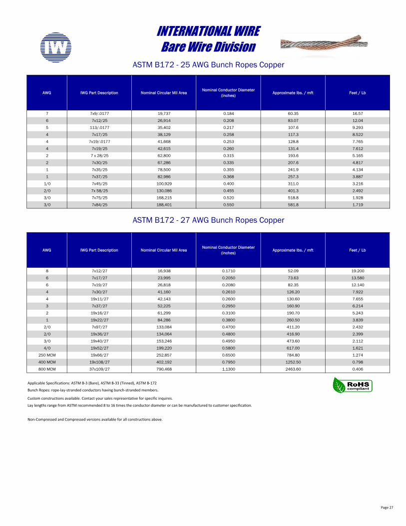
7 7x9/.0177 19,737 0.184 60.35 16.57
6 7x12/25 26,914 0.208 83.07 12.04
5 113/.0177 35,402 0.217 107.6 9.293
4 7x17/25 38,129 0.258 117.3 8.522
4 7x19/.0177 41,668 0.253 128.8 7.765
4 7x19/25 42,615 0.260 131.4 7.612
2 7 x 28/25 62,800 0.315 193.6 5.165
2 7x30/25 67,286 0.335 207.6 4.817
1 7x35/25 78,500 0.355 241.9 4.134
1 7x37/25 82,986 0.368 257.3 3.887
1/0 7x45/25 100,929 0.400 311.0 3.216
2/0 7x 58/25 130,086 0.455 401.3 2.492
3/0 7x75/25 168,215 0.520 518.8 1.928
3/0 7x84/25 188,401 0.550 581.8 1.719
AWG IWG Part Description Nominal Circular Mil AreaNominal Conductor Diameter
(inches)Approximate lbs. / mft Feet / Lb
8 7x12/27 16,938 0.1710 52.09 19.200
6 7x17/27 23,995 0.2050 73.63 13.580
6 7x19/27 26,818 0.2080 82.35 12.140
4 7x30/27 41,160 0.2610 126.20 7.922
4 19x11/27 42,143 0.2600 130.60 7.655
3 7x37/27 52,225 0.2950 160.90 6.214
2 19x16/27 61,299 0.3100 190.70 5.243
1 19x22/27 84,286 0.3800 260.50 3.839
2/0 7x97/27 133,084 0.4700 411.20 2.432
2/0 19x36/27 134,064 0.4800 416.90 2.399
3/0 19x40/27 153,246 0.4950 473.60 2.112
4/0 19x52/27 199,220 0.5800 617.00 1.621
250 MCM 19x66/27 252,857 0.6500 784.80 1.274
400 MCM 19x108/27 402,192 0.7950 1252.50 0.798
800 MCM 37x109/27 790,468 1.1300 2463.60 0.406
Custom constructions available. Contact your sales representative for specific inquires.
Lay lengths range from ASTM recommended 8 to 16 times the conductor diameter or can be manufactured to customer specification.
Non-Compressed and Compressed versions available for all constructions above.
INTERNATIONAL WIREBare Wire Division
ASTM B172 - 25 AWG Bunch Ropes Copper
Applicable Specifications: ASTM B-3 (Bare), ASTM B-33 (Tinned), ASTM B-172
Bunch Ropes: rope-lay-stranded conductors having bunch-stranded members.
ASTM B172 - 27 AWG Bunch Ropes Copper
Page 28
AWG IWG Part Description Nominal Circular Mil AreaNominal Conductor Diameter
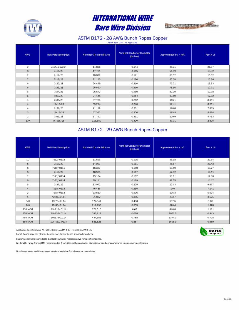
(inches)Approximate lbs. / mft Feet / Lb
9 7x14/.312mm 14,826 0.144 45.71 21.87
8 7x16/28 17,781 0.165 54.59 18.32
7 7x17/28 18,892 0.171 60.52 16.52
7 7x19/28 21,115 0.186 65.08 15.36
6 7x22/28 24,449 0.210 75.01 13.33
6 7x23/28 25,560 0.210 78.66 12.71
6 7x24/28 26,672 0.210 82.09 12.18
6 19x9/28 27,148 0.214 83.19 12.02
4 7x34/28 37,785 0.252 116.1 8.611
4 19x13/28 39,214 0.240 121.1 8.261
4 7x37/28 41,119 0.261 126.8 7.889
3 19x19/28 57,312 0.300 175.9 5.684
2 7x61/28 67,791 0.331 209.9 4.763
1/0 7x7x15/28 116,689 0.490 371.1 2.695
AWG IWG Part Description Nominal Circular Mil AreaNominal Conductor Diameter
(inches)Approximate lbs. / mft Feet / Lb
10 7x12/.0118 11,696 0.135 36.18 27.64
8 7x17/29 14,927 0.161 46.67 21.43
8 7x19/.0111 16,387 0.159 50.59 19.77
8 7x19/29 16,983 0.167 52.32 19.11
7 7x21/.0114 19,104 0.162 58.61 17.06
6 7x32/.0114 29,111 0.199 89.55 11.17
5 7x37/29 33,072 0.225 103.3 9.677
4 7x50/.0114 45,486 0.255 140 7.141
2 7x70/.0114 63,680 0.296 196.3 5.094
1 7x101/.0114 91,882 0.355 283.7 3.525
3/0 19x70/.0114 172,847 0.493 537.5 1.86
4/0 19x88/.0114 217,293 0.559 676.4 1.478
250 MCM 19x110/.0114 271,616 0.63 846.8 1.181
350 MCM 19x136/.0114 335,817 0.678 1060.5 0.943
450 MCM 19x176/.0114 434,586 0.788 1374.3 0.728
550 MCM 19x7x31/.0114 535,825 0.887 1696.9 0.589
Custom constructions available. Contact your sales representative for specific inquires.
Lay lengths range from ASTM recommended 8 to 16 times the conductor diameter or can be manufactured to customer specification.
Non-Compressed and Compressed versions available for all constructions above.
INTERNATIONAL WIREBare Wire Division
ASTM B172 - 28 AWG Bunch Ropes Copper
Applicable Specifications: ASTM B-3 (Bare), ASTM B-33 (Tinned), ASTM B-172
Bunch Ropes: rope-lay-stranded conductors having bunch-stranded members.
ASTM B172 - 29 AWG Bunch Ropes Copper
ASTM B174 Class J As Applicable
Page 29
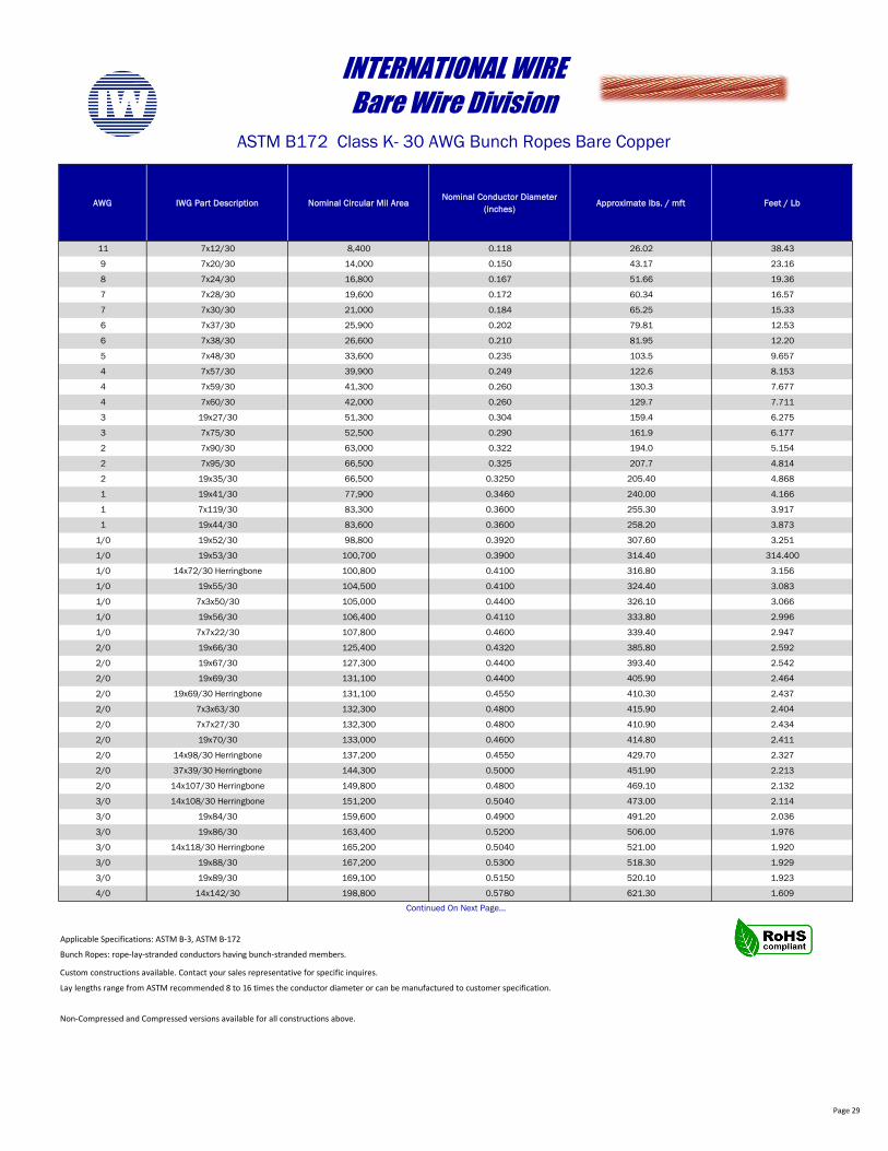
AWG IWG Part Description Nominal Circular Mil AreaNominal Conductor Diameter
(inches)Approximate lbs. / mft Feet / Lb
11 7x12/30 8,400 0.118 26.02 38.43
9 7x20/30 14,000 0.150 43.17 23.16
8 7x24/30 16,800 0.167 51.66 19.36
7 7x28/30 19,600 0.172 60.34 16.57
7 7x30/30 21,000 0.184 65.25 15.33
6 7x37/30 25,900 0.202 79.81 12.53
6 7x38/30 26,600 0.210 81.95 12.20
5 7x48/30 33,600 0.235 103.5 9.657
4 7x57/30 39,900 0.249 122.6 8.153
4 7x59/30 41,300 0.260 130.3 7.677
4 7x60/30 42,000 0.260 129.7 7.711
3 19x27/30 51,300 0.304 159.4 6.275
3 7x75/30 52,500 0.290 161.9 6.177
2 7x90/30 63,000 0.322 194.0 5.154
2 7x95/30 66,500 0.325 207.7 4.814
2 19x35/30 66,500 0.3250 205.40 4.868
1 19x41/30 77,900 0.3460 240.00 4.166
1 7x119/30 83,300 0.3600 255.30 3.917
1 19x44/30 83,600 0.3600 258.20 3.873
1/0 19x52/30 98,800 0.3920 307.60 3.251
1/0 19x53/30 100,700 0.3900 314.40 314.400
1/0 14x72/30 Herringbone 100,800 0.4100 316.80 3.156
1/0 19x55/30 104,500 0.4100 324.40 3.083
1/0 7x3x50/30 105,000 0.4400 326.10 3.066
1/0 19x56/30 106,400 0.4110 333.80 2.996
1/0 7x7x22/30 107,800 0.4600 339.40 2.947
2/0 19x66/30 125,400 0.4320 385.80 2.592
2/0 19x67/30 127,300 0.4400 393.40 2.542
2/0 19x69/30 131,100 0.4400 405.90 2.464
2/0 19x69/30 Herringbone 131,100 0.4550 410.30 2.437
2/0 7x3x63/30 132,300 0.4800 415.90 2.404
2/0 7x7x27/30 132,300 0.4800 410.90 2.434
2/0 19x70/30 133,000 0.4600 414.80 2.411
2/0 14x98/30 Herringbone 137,200 0.4550 429.70 2.327
2/0 37x39/30 Herringbone 144,300 0.5000 451.90 2.213
2/0 14x107/30 Herringbone 149,800 0.4800 469.10 2.132
3/0 14x108/30 Herringbone 151,200 0.5040 473.00 2.114
3/0 19x84/30 159,600 0.4900 491.20 2.036
3/0 19x86/30 163,400 0.5200 506.00 1.976
3/0 14x118/30 Herringbone 165,200 0.5040 521.00 1.920
3/0 19x88/30 167,200 0.5300 518.30 1.929
3/0 19x89/30 169,100 0.5150 520.10 1.923
4/0 14x142/30 198,800 0.5780 621.30 1.609
Custom constructions available. Contact your sales representative for specific inquires.
Lay lengths range from ASTM recommended 8 to 16 times the conductor diameter or can be manufactured to customer specification.
Non-Compressed and Compressed versions available for all constructions above.
Bunch Ropes: rope-lay-stranded conductors having bunch-stranded members.
Continued On Next Page…
INTERNATIONAL WIREBare Wire Division
ASTM B172 Class K- 30 AWG Bunch Ropes Bare Copper
Applicable Specifications: ASTM B-3, ASTM B-172
Page 30
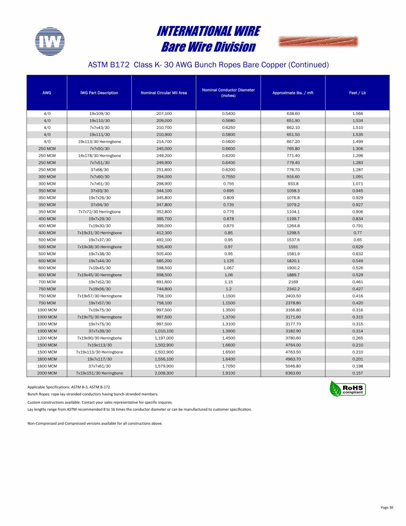
AWG IWG Part Description Nominal Circular Mil AreaNominal Conductor Diameter
(inches)Approximate lbs. / mft Feet / Lb
4/0 19x109/30 207,100 0.5400 638.60 1.566
4/0 19x110/30 209,000 0.5680 651.90 1.534
4/0 7x7x43/30 210,700 0.6250 662.10 1.510
4/0 19x111/30 210,900 0.5800 651.50 1.535
4/0 19x113/30 Herringbone 214,700 0.5600 667.20 1.499
250 MCM 7x7x50/30 245,000 0.6600 765.80 1.306
250 MCM 14x178/30 Herringbone 249,200 0.6200 771.40 1.296
250 MCM 7x7x51/30 249,900 0.6400 779.40 1.283
250 MCM 37x68/30 251,600 0.6200 776.70 1.287
300 MCM 7x7x60/30 294,000 0.7550 916.60 1.091
300 MCM 7x7x61/30 298,900 0.755 933.8 1.071
350 MCM 37x93/30 344,100 0.695 1058.3 0.945
350 MCM 19x7x26/30 345,800 0.809 1076.8 0.929
350 MCM 37x94/30 347,800 0.735 1079.2 0.927
350 MCM 7x7x72/30 Herringbone 352,800 0.775 1104.1 0.906
400 MCM 19x7x29/30 385,700 0.878 1199.7 0.834
400 MCM 7x19x30/30 399,000 0.875 1264.8 0.791
400 MCM 7x19x31/30 Herringbone 412,300 0.85 1298.5 0.77
500 MCM 19x7x37/30 492,100 0.95 1537.6 0.65
500 MCM 7x19x38/30 Herringbone 505,400 0.97 1591 0.629
500 MCM 19x7x38/30 505,400 0.95 1581.9 0.632
600 MCM 19x7x44/30 585,200 1.125 1820.1 0.549
600 MCM 7x19x45/30 598,500 1.067 1900.2 0.526
600 MCM 7x19x45/30 Herringbone 598,500 1.06 1889.7 0.529
700 MCM 19x7x52/30 691,600 1.15 2169 0.461
750 MCM 7x19x56/30 744,800 1.2 2342.2 0.427
750 MCM 7x19x57/30 Herringbone 758,100 1.1500 2403.50 0.416
750 MCM 19x7x57/30 758,100 1.1500 2378.80 0.420
1000 MCM 7x19x75/30 997,500 1.3500 3166.80 0.316
1000 MCM 7x19x75/30 Herringbone 997,500 1.3700 3171.60 0.315
1000 MCM 19x7x75/30 997,500 1.3100 3177.70 0.315
1000 MCM 37x7x39/30 1,010,100 1.3900 3182.90 0.314
1200 MCM 7x19x90/30 Herringbone 1,197,000 1.4500 3780.60 0.265
1500 MCM 7x19x113/30 1,502,900 1.6600 4764.00 0.210
1500 MCM 7x19x113/30 Herringbone 1,502,900 1.6500 4763.50 0.210
1600 MCM 19x7x117/30 1,556,100 1.6400 4963.70 0.201
1600 MCM 37x7x61/30 1,579,900 1.7050 5046.80 0.198
2000 MCM 7x19x151/30 Herringbone 2,008,300 1.9100 6363.60 0.157
Custom constructions available. Contact your sales representative for specific inquires.
Lay lengths range from ASTM recommended 8 to 16 times the conductor diameter or can be manufactured to customer specification.
Non-Compressed and Compressed versions available for all constructions above.
INTERNATIONAL WIREBare Wire Division
ASTM B172 Class K- 30 AWG Bunch Ropes Bare Copper (Continued)
Applicable Specifications: ASTM B-3, ASTM B-172
Bunch Ropes: rope-lay-stranded conductors having bunch-stranded members.
Page 31
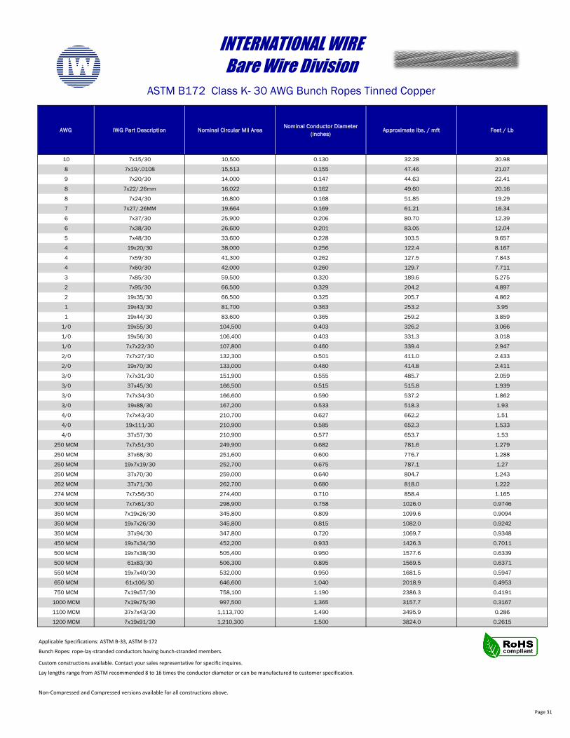
AWG IWG Part Description Nominal Circular Mil AreaNominal Conductor Diameter
(inches)Approximate lbs. / mft Feet / Lb
10 7x15/30 10,500 0.130 32.28 30.98
8 7x19/.0108 15,513 0.155 47.46 21.07
9 7x20/30 14,000 0.147 44.63 22.41
8 7x22/.26mm 16,022 0.162 49.60 20.16
8 7x24/30 16,800 0.168 51.85 19.29
7 7x27/.26MM 19,664 0.169 61.21 16.34
6 7x37/30 25,900 0.206 80.70 12.39
6 7x38/30 26,600 0.201 83.05 12.04
5 7x48/30 33,600 0.228 103.5 9.657
4 19x20/30 38,000 0.256 122.4 8.167
4 7x59/30 41,300 0.262 127.5 7.843
4 7x60/30 42,000 0.260 129.7 7.711
3 7x85/30 59,500 0.320 189.6 5.275
2 7x95/30 66,500 0.329 204.2 4.897
2 19x35/30 66,500 0.325 205.7 4.862
1 19x43/30 81,700 0.363 253.2 3.95
1 19x44/30 83,600 0.365 259.2 3.859
1/0 19x55/30 104,500 0.403 326.2 3.066
1/0 19x56/30 106,400 0.403 331.3 3.018
1/0 7x7x22/30 107,800 0.460 339.4 2.947
2/0 7x7x27/30 132,300 0.501 411.0 2.433
2/0 19x70/30 133,000 0.460 414.8 2.411
3/0 7x7x31/30 151,900 0.555 485.7 2.059
3/0 37x45/30 166,500 0.515 515.8 1.939
3/0 7x7x34/30 166,600 0.590 537.2 1.862
3/0 19x88/30 167,200 0.533 518.3 1.93
4/0 7x7x43/30 210,700 0.627 662.2 1.51
4/0 19x111/30 210,900 0.585 652.3 1.533
4/0 37x57/30 210,900 0.577 653.7 1.53
250 MCM 7x7x51/30 249,900 0.682 781.6 1.279
250 MCM 37x68/30 251,600 0.600 776.7 1.288
250 MCM 19x7x19/30 252,700 0.675 787.1 1.27
250 MCM 37x70/30 259,000 0.640 804.7 1.243
262 MCM 37x71/30 262,700 0.680 818.0 1.222
274 MCM 7x7x56/30 274,400 0.710 858.4 1.165
300 MCM 7x7x61/30 298,900 0.758 1026.0 0.9746
350 MCM 7x19x26/30 345,800 0.809 1099.6 0.9094
350 MCM 19x7x26/30 345,800 0.815 1082.0 0.9242
350 MCM 37x94/30 347,800 0.720 1069.7 0.9348
450 MCM 19x7x34/30 452,200 0.933 1426.3 0.7011
500 MCM 19x7x38/30 505,400 0.950 1577.6 0.6339
500 MCM 61x83/30 506,300 0.895 1569.5 0.6371
550 MCM 19x7x40/30 532,000 0.950 1681.5 0.5947
650 MCM 61x106/30 646,600 1.040 2018.9 0.4953
750 MCM 7x19x57/30 758,100 1.190 2386.3 0.4191
1000 MCM 7x19x75/30 997,500 1.365 3157.7 0.3167
1100 MCM 37x7x43/30 1,113,700 1.490 3495.9 0.286
1200 MCM 7x19x91/30 1,210,300 1.500 3824.0 0.2615
Custom constructions available. Contact your sales representative for specific inquires.
Lay lengths range from ASTM recommended 8 to 16 times the conductor diameter or can be manufactured to customer specification.
Non-Compressed and Compressed versions available for all constructions above.
Applicable Specifications: ASTM B-33, ASTM B-172
Bunch Ropes: rope-lay-stranded conductors having bunch-stranded members.
INTERNATIONAL WIREBare Wire Division
ASTM B172 Class K- 30 AWG Bunch Ropes Tinned Copper
Page 32
AWG IWG Part Description Nominal Circular Mil AreaNominal Conductor Diameter
(inches)Approximate lbs. / mft Feet / Lb
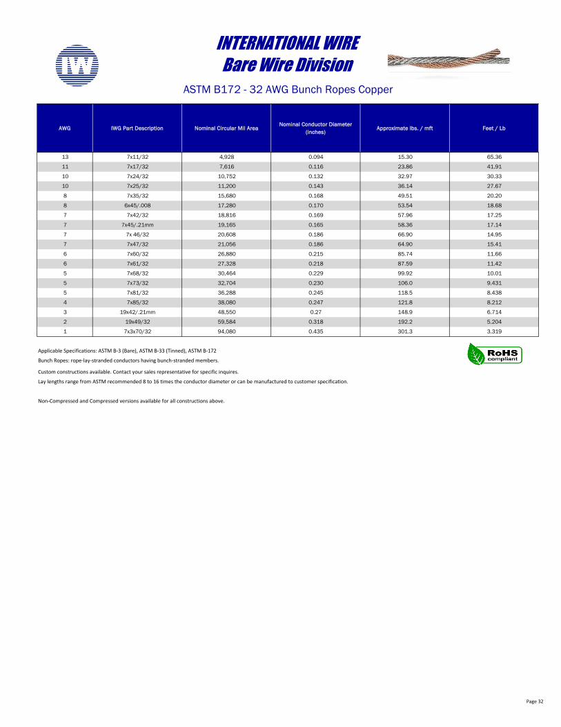
13 7x11/32 4,928 0.094 15.30 65.36
11 7x17/32 7,616 0.116 23.86 41.91
10 7x24/32 10,752 0.132 32.97 30.33
10 7x25/32 11,200 0.143 36.14 27.67
8 7x35/32 15,680 0.168 49.51 20.20
8 6x45/.008 17,280 0.170 53.54 18.68
7 7x42/32 18,816 0.169 57.96 17.25
7 7x45/.21mm 19,165 0.165 58.36 17.14
7 7x 46/32 20,608 0.186 66.90 14.95
7 7x47/32 21,056 0.186 64.90 15.41
6 7x60/32 26,880 0.215 85.74 11.66
6 7x61/32 27,328 0.218 87.59 11.42
5 7x68/32 30,464 0.229 99.92 10.01
5 7x73/32 32,704 0.230 106.0 9.431
5 7x81/32 36,288 0.245 118.5 8.438
4 7x85/32 38,080 0.247 121.8 8.212
3 19x42/.21mm 48,550 0.27 148.9 6.714
2 19x49/32 59,584 0.318 192.2 5.204
1 7x3x70/32 94,080 0.435 301.3 3.319
Custom constructions available. Contact your sales representative for specific inquires.
Lay lengths range from ASTM recommended 8 to 16 times the conductor diameter or can be manufactured to customer specification.
Non-Compressed and Compressed versions available for all constructions above.
INTERNATIONAL WIREBare Wire Division
ASTM B172 - 32 AWG Bunch Ropes Copper
Applicable Specifications: ASTM B-3 (Bare), ASTM B-33 (Tinned), ASTM B-172
Bunch Ropes: rope-lay-stranded conductors having bunch-stranded members.
Page 33
AWG IWG Part Description Nominal Circular Mil AreaNominal Conductor Diameter
(inches)Approximate lbs. / mft Feet / Lb
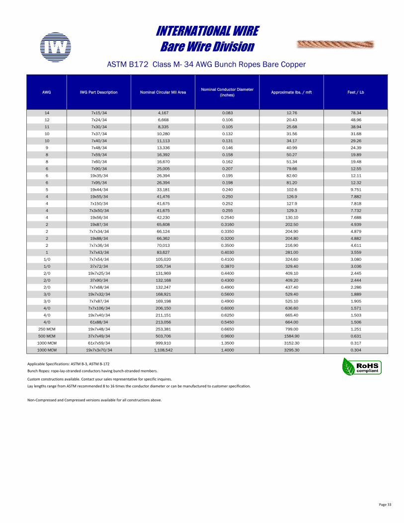
14 7x15/34 4,167 0.083 12.76 78.34
12 7x24/34 6,668 0.106 20.43 48.96
11 7x30/34 8,335 0.105 25.68 38.94
10 7x37/34 10,280 0.132 31.56 31.68
10 7x40/34 11,113 0.131 34.17 29.26
9 7x48/34 13,336 0.146 40.99 24.39
8 7x59/34 16,392 0.158 50.27 19.89
8 7x60/34 16,670 0.162 51.34 19.48
6 7x90/34 25,005 0.207 79.66 12.55
6 19x35/34 26,394 0.195 82.60 12.11
6 7x95/34 26,394 0.198 81.20 12.32
5 19x44/34 33,181 0.240 102.6 9.751
4 19x55/34 41,476 0.250 126.9 7.882
4 7x150/34 41,675 0.252 127.9 7.818
4 7x3x50/34 41,675 0.255 129.3 7.732
4 19x56/34 42,230 0.2540 130.10 7.688
2 19x87/34 65,608 0.3160 202.50 4.939
2 7x7x34/34 66,124 0.3350 204.90 4.879
2 19x88/34 66,362 0.3200 204.80 4.882
2 7x7x36/34 70,013 0.3500 216.90 4.611
1 7x7x43/34 83,627 0.4030 281.00 3.559
1/0 7x7x54/34 105,020 0.4100 324.60 3.080
1/0 37x72/34 105,734 0.3870 329.40 3.036
2/0 19x7x25/34 131,969 0.4400 409.10 2.445
2/0 37x90/34 132,168 0.4300 409.20 2.444
2/0 7x7x68/34 132,247 0.4900 437.40 2.286
3/0 19x7x32/34 168,921 0.5600 529.40 1.889
3/0 7x7x87/34 169,198 0.4900 525.10 1.905
4/0 7x7x106/34 206,150 0.6000 636.60 1.571
4/0 19x7x40/34 211,151 0.6250 665.40 1.503
4/0 61x88/34 213,056 0.5450 664.00 1.506
250 MCM 19x7x48/34 253,381 0.6650 799.00 1.251
500 MCM 37x7x49/34 503,706 0.9600 1584.90 0.631
1000 MCM 61x7x59/34 999,910 1.3500 3152.30 0.317
1000 MCM 19x7x3x70/34 1,108,542 1.4000 3295.30 0.304
Custom constructions available. Contact your sales representative for specific inquires.
Lay lengths range from ASTM recommended 8 to 16 times the conductor diameter or can be manufactured to customer specification.
Non-Compressed and Compressed versions available for all constructions above.
INTERNATIONAL WIREBare Wire Division
ASTM B172 Class M- 34 AWG Bunch Ropes Bare Copper
Applicable Specifications: ASTM B-3, ASTM B-172
Bunch Ropes: rope-lay-stranded conductors having bunch-stranded members.
Page 34
AWG IWG Part Description Nominal Circular Mil AreaNominal Conductor Diameter
(inches)Approximate lbs. / mft Feet / Lb
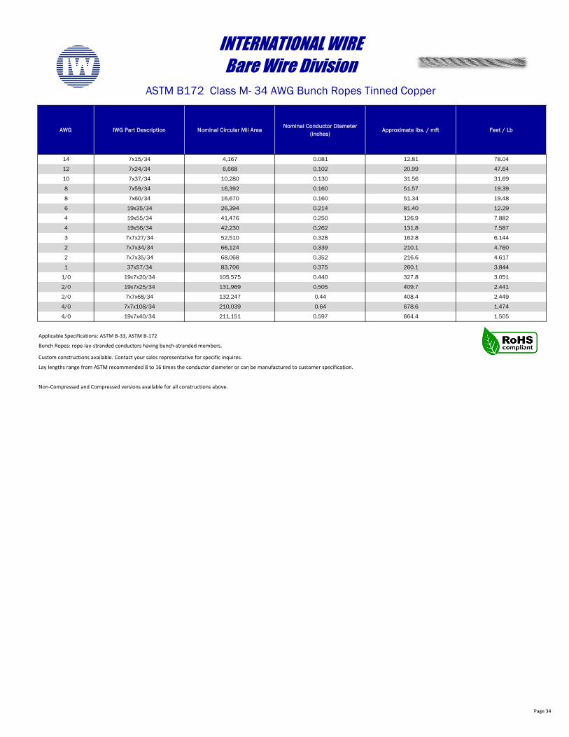
14 7x15/34 4,167 0.081 12.81 78.04
12 7x24/34 6,668 0.102 20.99 47.64
10 7x37/34 10,280 0.130 31.56 31.69
8 7x59/34 16,392 0.160 51.57 19.39
8 7x60/34 16,670 0.160 51.34 19.48
6 19x35/34 26,394 0.214 81.40 12.29
4 19x55/34 41,476 0.250 126.9 7.882
4 19x56/34 42,230 0.262 131.8 7.587
3 7x7x27/34 52,510 0.328 162.8 6.144
2 7x7x34/34 66,124 0.339 210.1 4.760
2 7x7x35/34 68,068 0.352 216.6 4.617
1 37x57/34 83,706 0.375 260.1 3.844
1/0 19x7x20/34 105,575 0.440 327.8 3.051
2/0 19x7x25/34 131,969 0.505 409.7 2.441
2/0 7x7x68/34 132,247 0.44 408.4 2.449
4/0 7x7x108/34 210,039 0.64 678.6 1.474
4/0 19x7x40/34 211,151 0.597 664.4 1.505
Custom constructions available. Contact your sales representative for specific inquires.
Lay lengths range from ASTM recommended 8 to 16 times the conductor diameter or can be manufactured to customer specification.
Non-Compressed and Compressed versions available for all constructions above.
Bunch Ropes: rope-lay-stranded conductors having bunch-stranded members.
INTERNATIONAL WIREBare Wire Division
ASTM B172 Class M- 34 AWG Bunch Ropes Tinned Copper
Applicable Specifications: ASTM B-33, ASTM B-172
Page 35
AWG IWG Part Description Nominal Circular Mil AreaNominal Conductor Diameter
(inches)Approximate lbs. / mft Feet / Lb
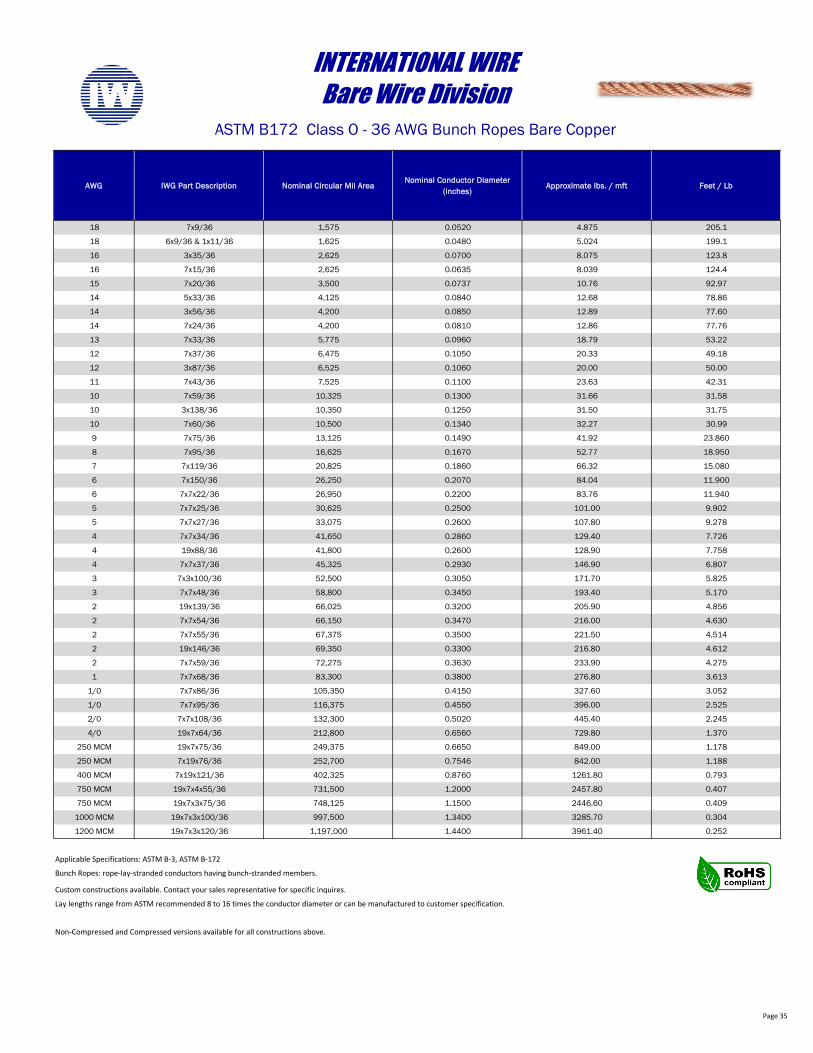
18 7x9/36 1,575 0.0520 4.875 205.1
18 6x9/36 & 1x11/36 1,625 0.0480 5.024 199.1
16 3x35/36 2,625 0.0700 8.075 123.8
16 7x15/36 2,625 0.0635 8.039 124.4
15 7x20/36 3,500 0.0737 10.76 92.97
14 5x33/36 4,125 0.0840 12.68 78.86
14 3x56/36 4,200 0.0850 12.89 77.60
14 7x24/36 4,200 0.0810 12.86 77.76
13 7x33/36 5,775 0.0960 18.79 53.22
12 7x37/36 6,475 0.1050 20.33 49.18
12 3x87/36 6,525 0.1060 20.00 50.00
11 7x43/36 7,525 0.1100 23.63 42.31
10 7x59/36 10,325 0.1300 31.66 31.58
10 3x138/36 10,350 0.1250 31.50 31.75
10 7x60/36 10,500 0.1340 32.27 30.99
9 7x75/36 13,125 0.1490 41.92 23.860
8 7x95/36 16,625 0.1670 52.77 18.950
7 7x119/36 20,825 0.1860 66.32 15.080
6 7x150/36 26,250 0.2070 84.04 11.900
6 7x7x22/36 26,950 0.2200 83.76 11.940
5 7x7x25/36 30,625 0.2500 101.00 9.902
5 7x7x27/36 33,075 0.2600 107.80 9.278
4 7x7x34/36 41,650 0.2860 129.40 7.726
4 19x88/36 41,800 0.2600 128.90 7.758
4 7x7x37/36 45,325 0.2930 146.90 6.807
3 7x3x100/36 52,500 0.3050 171.70 5.825
3 7x7x48/36 58,800 0.3450 193.40 5.170
2 19x139/36 66,025 0.3200 205.90 4.856
2 7x7x54/36 66,150 0.3470 216.00 4.630
2 7x7x55/36 67,375 0.3500 221.50 4.514
2 19x146/36 69,350 0.3300 216.80 4.612
2 7x7x59/36 72,275 0.3630 233.90 4.275
1 7x7x68/36 83,300 0.3800 276.80 3.613
1/0 7x7x86/36 105,350 0.4150 327.60 3.052
1/0 7x7x95/36 116,375 0.4550 396.00 2.525
2/0 7x7x108/36 132,300 0.5020 445.40 2.245
4/0 19x7x64/36 212,800 0.6560 729.80 1.370
250 MCM 19x7x75/36 249,375 0.6650 849.00 1.178
250 MCM 7x19x76/36 252,700 0.7546 842.00 1.188
400 MCM 7x19x121/36 402,325 0.8760 1261.80 0.793
750 MCM 19x7x4x55/36 731,500 1.2000 2457.80 0.407
750 MCM 19x7x3x75/36 748,125 1.1500 2446.60 0.409
1000 MCM 19x7x3x100/36 997,500 1.3400 3285.70 0.304
1200 MCM 19x7x3x120/36 1,197,000 1.4400 3961.40 0.252
Custom constructions available. Contact your sales representative for specific inquires.
Lay lengths range from ASTM recommended 8 to 16 times the conductor diameter or can be manufactured to customer specification.
Non-Compressed and Compressed versions available for all constructions above.
Bunch Ropes: rope-lay-stranded conductors having bunch-stranded members.
INTERNATIONAL WIREBare Wire Division
ASTM B172 Class O - 36 AWG Bunch Ropes Bare Copper
Applicable Specifications: ASTM B-3, ASTM B-172
Page 36
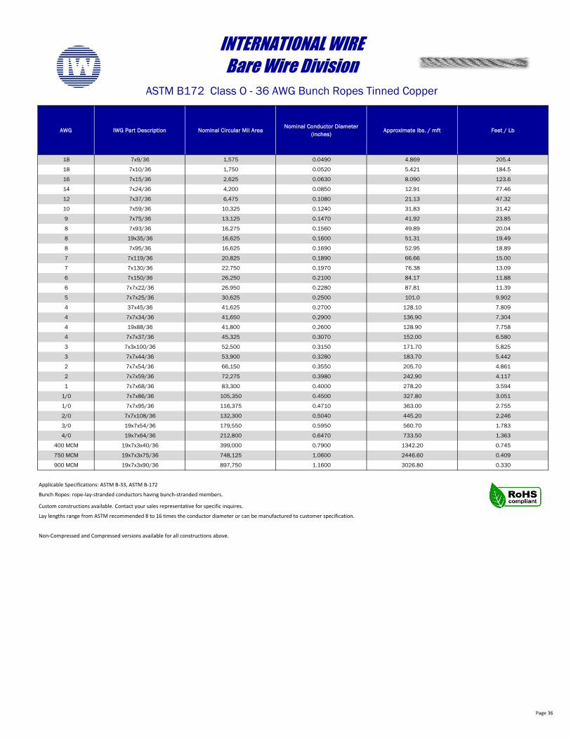
AWG IWG Part Description Nominal Circular Mil AreaNominal Conductor Diameter
(inches)Approximate lbs. / mft Feet / Lb
18 7x9/36 1,575 0.0490 4.869 205.4
18 7x10/36 1,750 0.0520 5.421 184.5
16 7x15/36 2,625 0.0630 8.090 123.6
14 7x24/36 4,200 0.0850 12.91 77.46
12 7x37/36 6,475 0.1080 21.13 47.32
10 7x59/36 10,325 0.1240 31.83 31.42
9 7x75/36 13,125 0.1470 41.92 23.85
8 7x93/36 16,275 0.1560 49.89 20.04
8 19x35/36 16,625 0.1600 51.31 19.49
8 7x95/36 16,625 0.1690 52.95 18.89
7 7x119/36 20,825 0.1890 66.66 15.00
7 7x130/36 22,750 0.1970 76.38 13.09
6 7x150/36 26,250 0.2100 84.17 11.88
6 7x7x22/36 26,950 0.2280 87.81 11.39
5 7x7x25/36 30,625 0.2500 101.0 9.902
4 37x45/36 41,625 0.2700 128.10 7.809
4 7x7x34/36 41,650 0.2900 136.90 7.304
4 19x88/36 41,800 0.2600 128.90 7.758
4 7x7x37/36 45,325 0.3070 152.00 6.580
3 7x3x100/36 52,500 0.3150 171.70 5.825
3 7x7x44/36 53,900 0.3280 183.70 5.442
2 7x7x54/36 66,150 0.3550 205.70 4.861
2 7x7x59/36 72,275 0.3980 242.90 4.117
1 7x7x68/36 83,300 0.4000 278.20 3.594
1/0 7x7x86/36 105,350 0.4500 327.80 3.051
1/0 7x7x95/36 116,375 0.4710 363.00 2.755
2/0 7x7x108/36 132,300 0.5040 445.20 2.246
3/0 19x7x54/36 179,550 0.5950 560.70 1.783
4/0 19x7x64/36 212,800 0.6470 733.50 1.363
400 MCM 19x7x3x40/36 399,000 0.7900 1342.20 0.745
750 MCM 19x7x3x75/36 748,125 1.0600 2446.60 0.409
900 MCM 19x7x3x90/36 897,750 1.1600 3026.80 0.330
Custom constructions available. Contact your sales representative for specific inquires.
Lay lengths range from ASTM recommended 8 to 16 times the conductor diameter or can be manufactured to customer specification.
Non-Compressed and Compressed versions available for all constructions above.
INTERNATIONAL WIREBare Wire Division
ASTM B172 Class O - 36 AWG Bunch Ropes Tinned Copper
Applicable Specifications: ASTM B-33, ASTM B-172
Bunch Ropes: rope-lay-stranded conductors having bunch-stranded members.
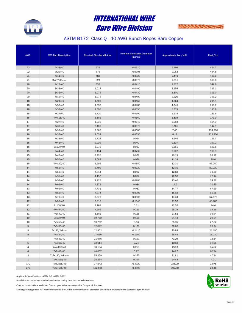
Page 37
AWG IWG Part Description Nominal Circular Mil AreaNominal Conductor Diameter
(inches)Approximate lbs. / mft Feet / Lb
22 2x33/40 676 0.0310 2.199 454.7
22 3x22/40 676 0.0305 2.063 484.8
21 7x11/40 788 0.0320 2.440 409.9
21 3x27/.08mm 829 0.0370 2.611 383.0
20 7x13/40 932 0.0410 2.877 347.6
20 3x33/40 1,014 0.0400 3.154 317.1
20 3x35/40 1,075 0.0430 3.301 303.0
20 7x15/40 1,075 0.0400 3.320 301.2
18 7x21/40 1,505 0.0460 4.664 214.4
18 3x50/40 1,536 0.0480 4.745 210.7
18 5x33/40 1,690 0.0550 5.379 185.9
18 7x24/40 1,720 0.0500 5.275 189.6
18 4x4x11/40 1,802 0.0560 5.816 171.9
17 7x27/40 1,935 0.0540 6.063 164.9
17 7x30/40 2,150 0.0570 6.761 147.9
17 7x33/40 2,365 0.0580 7.45 134.200
16 7x37/40 2,652 0.0650 8.18 122.300
16 7x38/40 2,724 0.064 8.646 115.7
16 7x41/40 2,939 0.072 9.327 107.2
16 3x100/40 3,072 0.067 9.651 103.6
15 7x44/40 3,154 0.0736 9.907 100.9
15 7x45/40 3,226 0.072 10.19 98.17
15 7x50/40 3,584 0.076 11.29 88.6
15 4x4x22/40 3,604 0.0850 12.31 81.250
14 7x53/40 3,799 0.0720 12.16 82.220
14 7x56/40 4,014 0.082 12.68 78.89
14 7x58/40 4,157 0.077 12.96 77.14
14 7x59/40 4,229 0.0785 13.46 74.27
14 7x61/40 4,372 0.084 14.2 70.45
13 7x66/40 4,731 0.087 14.77 67.69
13 7x68/40 4,874 0.0906 15.18 65.86
13 7x75/40 5,376 0.0900 17.34 57.670
12 7x95/40 6,810 0.1040 21.52 46.480
12 7x100/40 7,168 0.11 22.52 44.4
12 4x4x44/40 7,209 0.113 25.28 39.55
11 7x3x40/40 8,602 0.115 27.82 35.94
10 7x150/40 10,752 0.128 34.43 29.04
10 7x3x50/40 10,752 0.13 35.95 27.82
9 7x3x56/40 12,042 0.166 39.62 25.24
9 7x180/.08mm 12,902 0.1415 40.83 24.490
8 7x7x34/40 17,060 0.1960 55.45 18.030
7 7x7x43/40 21,576 0.191 73.29 13.64
5 7x7x65/40 32,614 0.24 108.8 9.195
4 7x4x133/40 38,134 0.255 118.3 8.452
4 7x7x89/40 44,657 0.27 148.7 6.724
2 7x7x130/.08 mm 65,229 0.375 212.1 4.714
1 7x7x3x50/40 75,264 0.345 249.4 4.01
1/0 7x7x3x65/40 97,843 0.4120 325.20 3.075
2/0 7x7x7x35/40 122,931 0.4890 392.80 2.546
Custom constructions available. Contact your sales representative for specific inquires.
Lay lengths range from ASTM recommended 8 to 16 times the conductor diameter or can be manufactured to customer specification.
Bunch Ropes: rope-lay-stranded conductors having bunch-stranded members.
INTERNATIONAL WIREBare Wire Division
ASTM B172 Class Q - 40 AWG Bunch Ropes Bare Copper
Applicable Specifications: ASTM B-3, ASTM B-172
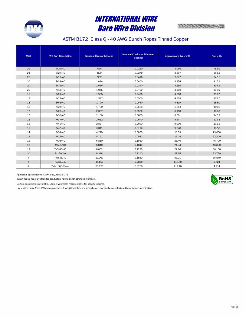
Page 38
AWG IWG Part Description Nominal Circular Mil AreaNominal Conductor Diameter
(inches)Approximate lbs. / mft Feet / Lb
22 3x22/40 676 0.0350 2.066 483.9
21 3x27/40 829 0.0370 2.607 383.5
20 7x13/40 932 0.0410 2.877 347.6
20 3x33/40 1,014 0.0400 3.154 317.1
20 3x35/40 1,075 0.0390 3.295 303.5
20 7x15/40 1,075 0.0420 3.302 302.9
18 7x21/40 1,505 0.0480 4.680 213.7
18 7x22/40 1,577 0.0500 4.909 203.7
18 3x56/40 1,720 0.0540 5.319 188.0
18 7x24/40 1,720 0.0526 5.284 189.2
17 7x28/40 2,007 0.0560 6.180 161.8
17 7x30/40 2,150 0.0600 6.761 147.9
16 7x37/40 2,652 0.0670 8.177 122.3
16 7x40/40 2,867 0.0690 9.000 111.1
15 7x42/40 3,011 0.0710 9.278 107.8
14 7x59/40 4,229 0.0850 13.59 73.600
13 7x72/40 5,161 0.0942 16.08 62.200
12 7x95/40 6,810 0.1080 21.40 46.720
12 19x35/40 6,810 0.1040 21.34 46.860
19 7x3x40/40 8,602 0.1220 27.66 36.150
10 7x130/40 9,318 0.1210 29.65 33.720
7 7x7x38/40 19,067 0.1850 63.01 15.870
4 7x7x89/40 44,657 0.2830 148.70 6.724
2 7x7x130/.08mm 65,229 0.3750 212.10 4.714
Custom constructions available. Contact your sales representative for specific inquires.
Lay lengths range from ASTM recommended 8 to 16 times the conductor diameter or can be manufactured to customer specification.
INTERNATIONAL WIREBare Wire Division
ASTM B172 Class Q - 40 AWG Bunch Ropes Tinned Copper
Applicable Specifications: ASTM B-33, ASTM B-172
Bunch Ropes: rope-lay-stranded conductors having bunch-stranded members.
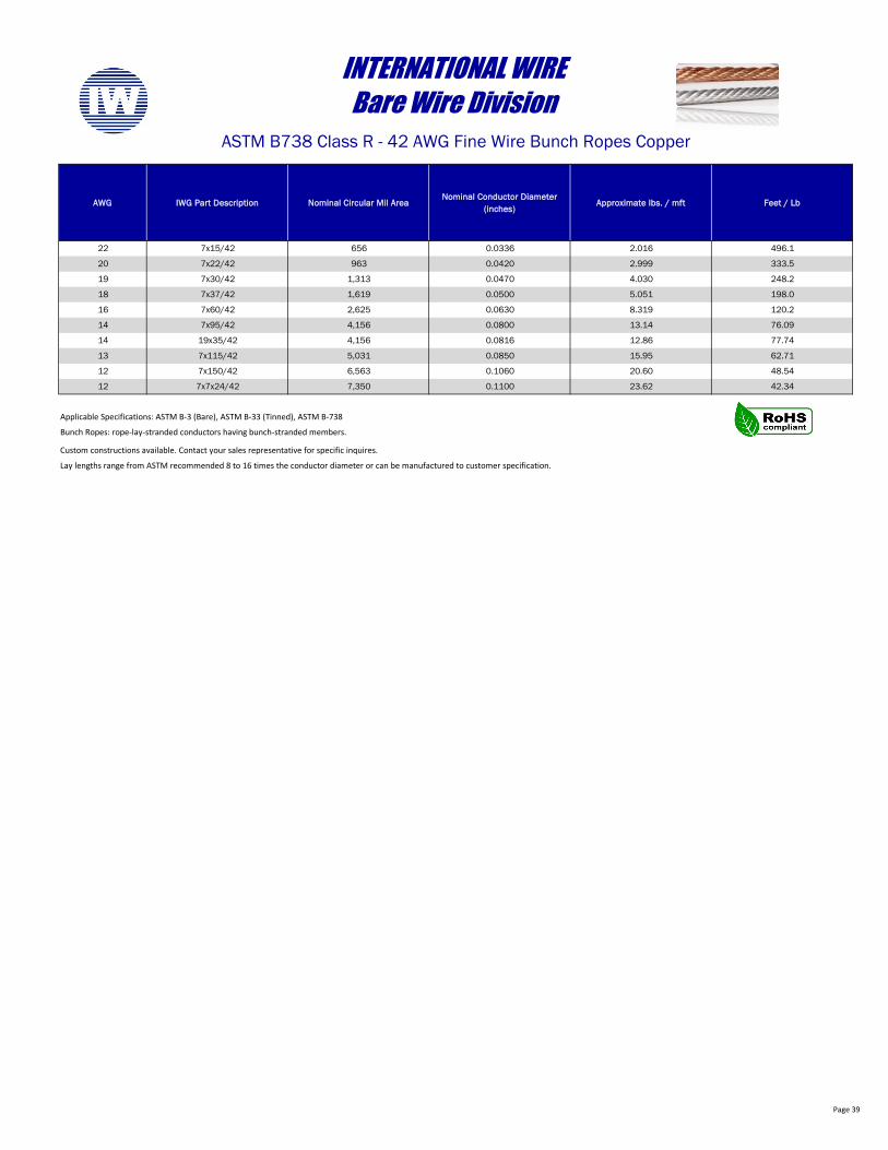
Page 39
AWG IWG Part Description Nominal Circular Mil AreaNominal Conductor Diameter
(inches)Approximate lbs. / mft Feet / Lb
22 7x15/42 656 0.0336 2.016 496.1
20 7x22/42 963 0.0420 2.999 333.5
19 7x30/42 1,313 0.0470 4.030 248.2
18 7x37/42 1,619 0.0500 5.051 198.0
16 7x60/42 2,625 0.0630 8.319 120.2
14 7x95/42 4,156 0.0800 13.14 76.09
14 19x35/42 4,156 0.0816 12.86 77.74
13 7x115/42 5,031 0.0850 15.95 62.71
12 7x150/42 6,563 0.1060 20.60 48.54
12 7x7x24/42 7,350 0.1100 23.62 42.34
Custom constructions available. Contact your sales representative for specific inquires.
Lay lengths range from ASTM recommended 8 to 16 times the conductor diameter or can be manufactured to customer specification.
INTERNATIONAL WIREBare Wire Division
ASTM B738 Class R - 42 AWG Fine Wire Bunch Ropes Copper
Applicable Specifications: ASTM B-3 (Bare), ASTM B-33 (Tinned), ASTM B-738
Bunch Ropes: rope-lay-stranded conductors having bunch-stranded members.
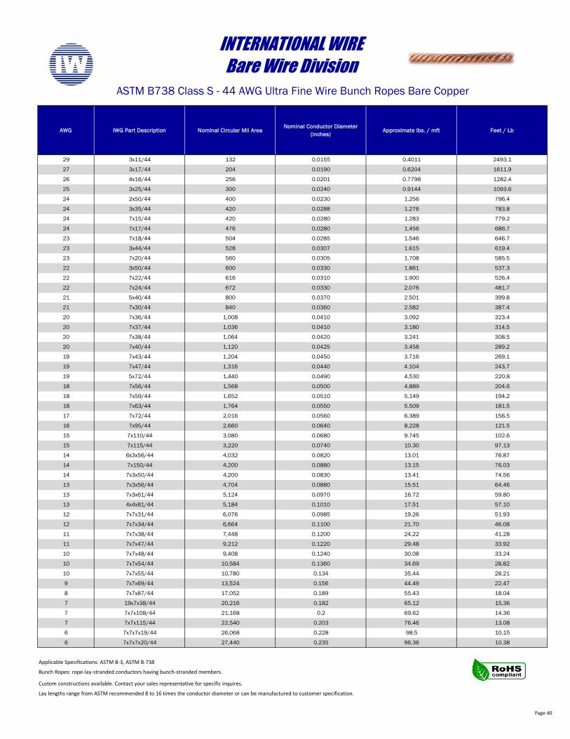
Page 40
AWG IWG Part Description Nominal Circular Mil AreaNominal Conductor Diameter
(inches)Approximate lbs. / mft Feet / Lb
29 3x11/44 132 0.0155 0.4011 2493.1
27 3x17/44 204 0.0190 0.6204 1611.9
26 4x16/44 256 0.0201 0.7798 1282.4
25 3x25/44 300 0.0240 0.9144 1093.6
24 2x50/44 400 0.0230 1.256 796.4
24 3x35/44 420 0.0288 1.276 783.8
24 7x15/44 420 0.0280 1.283 779.2
24 7x17/44 476 0.0280 1.456 686.7
23 7x18/44 504 0.0285 1.546 646.7
23 3x44/44 528 0.0307 1.615 619.4
23 7x20/44 560 0.0305 1.708 585.5
22 3x50/44 600 0.0330 1.861 537.3
22 7x22/44 616 0.0310 1.900 526.4
22 7x24/44 672 0.0330 2.076 481.7
21 5x40/44 800 0.0370 2.501 399.8
21 7x30/44 840 0.0360 2.582 387.4
20 7x36/44 1,008 0.0410 3.092 323.4
20 7x37/44 1,036 0.0410 3.180 314.5
20 7x38/44 1,064 0.0420 3.241 308.5
20 7x40/44 1,120 0.0425 3.458 289.2
19 7x43/44 1,204 0.0450 3.716 269.1
19 7x47/44 1,316 0.0440 4.104 243.7
19 5x72/44 1,440 0.0490 4.530 220.8
18 7x56/44 1,568 0.0500 4.889 204.6
18 7x59/44 1,652 0.0510 5.149 194.2
18 7x63/44 1,764 0.0550 5.509 181.5
17 7x72/44 2,016 0.0560 6.389 156.5
16 7x95/44 2,660 0.0640 8.228 121.5
15 7x110/44 3,080 0.0680 9.745 102.6
15 7x115/44 3,220 0.0740 10.30 97.13
14 6x3x56/44 4,032 0.0820 13.01 76.87
14 7x150/44 4,200 0.0880 13.15 76.03
14 7x3x50/44 4,200 0.0830 13.41 74.56
13 7x3x56/44 4,704 0.0880 15.51 64.46
13 7x3x61/44 5,124 0.0970 16.72 59.80
13 4x4x81/44 5,184 0.1010 17.51 57.10
12 7x7x31/44 6,076 0.0985 19.26 51.93
12 7x7x34/44 6,664 0.1100 21.70 46.08
11 7x7x38/44 7,448 0.1200 24.22 41.28
11 7x7x47/44 9,212 0.1220 29.48 33.92
10 7x7x48/44 9,408 0.1240 30.08 33.24
10 7x7x54/44 10,584 0.1360 34.69 28.82
10 7x7x55/44 10,780 0.134 35.44 28.21
9 7x7x69/44 13,524 0.156 44.49 22.47
8 7x7x87/44 17,052 0.189 55.43 18.04
7 19x7x38/44 20,216 0.182 65.12 15.36
7 7x7x108/44 21,168 0.2 69.62 14.36
7 7x7x115/44 22,540 0.203 76.46 13.08
6 7x7x7x19/44 26,068 0.228 98.5 10.15
6 7x7x7x20/44 27,440 0.235 96.36 10.38
Custom constructions available. Contact your sales representative for specific inquires.
Lay lengths range from ASTM recommended 8 to 16 times the conductor diameter or can be manufactured to customer specification.
INTERNATIONAL WIREBare Wire Division
ASTM B738 Class S - 44 AWG Ultra Fine Wire Bunch Ropes Bare Copper
Applicable Specifications: ASTM B-3, ASTM B-738
Bunch Ropes: rope-lay-stranded conductors having bunch-stranded members.
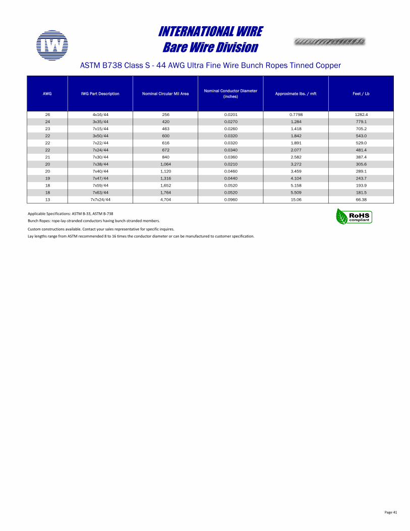
Page 41
AWG IWG Part Description Nominal Circular Mil AreaNominal Conductor Diameter
(inches)Approximate lbs. / mft Feet / Lb
26 4x16/44 256 0.0201 0.7798 1282.4
24 3x35/44 420 0.0270 1.284 779.1
23 7x15/44 463 0.0260 1.418 705.2
22 3x50/44 600 0.0320 1.842 543.0
22 7x22/44 616 0.0320 1.891 529.0
22 7x24/44 672 0.0340 2.077 481.4
21 7x30/44 840 0.0360 2.582 387.4
20 7x38/44 1,064 0.0210 3.272 305.6
20 7x40/44 1,120 0.0460 3.459 289.1
19 7x47/44 1,316 0.0440 4.104 243.7
18 7x59/44 1,652 0.0520 5.158 193.9
18 7x63/44 1,764 0.0520 5.509 181.5
13 7x7x24/44 4,704 0.0960 15.06 66.38
Custom constructions available. Contact your sales representative for specific inquires.
Lay lengths range from ASTM recommended 8 to 16 times the conductor diameter or can be manufactured to customer specification.
INTERNATIONAL WIREBare Wire Division
ASTM B738 Class S - 44 AWG Ultra Fine Wire Bunch Ropes Tinned Copper
Applicable Specifications: ASTM B-33, ASTM B-738
Bunch Ropes: rope-lay-stranded conductors having bunch-stranded members.
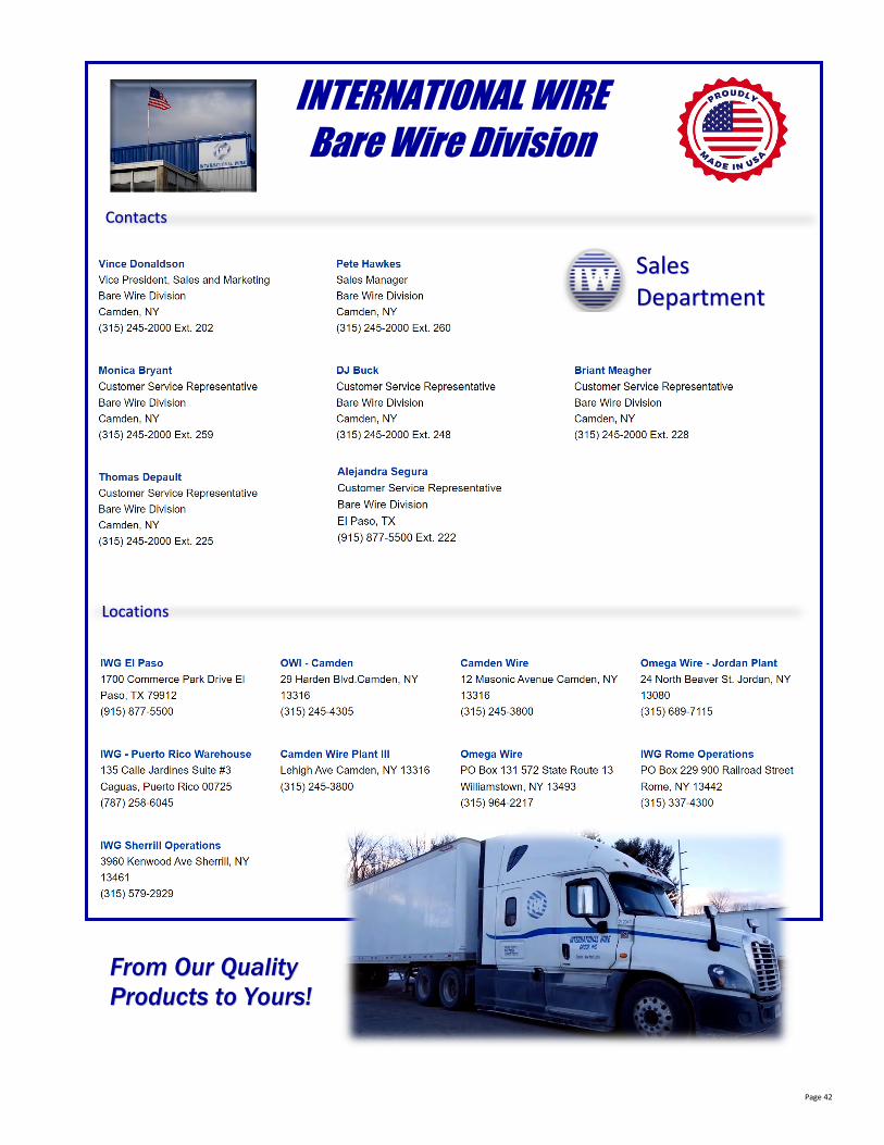
Page 42
INTERNATIONAL WIREBare Wire Division
SalesDepartment
Locations
Contacts
From Our Quality Products to Yours!
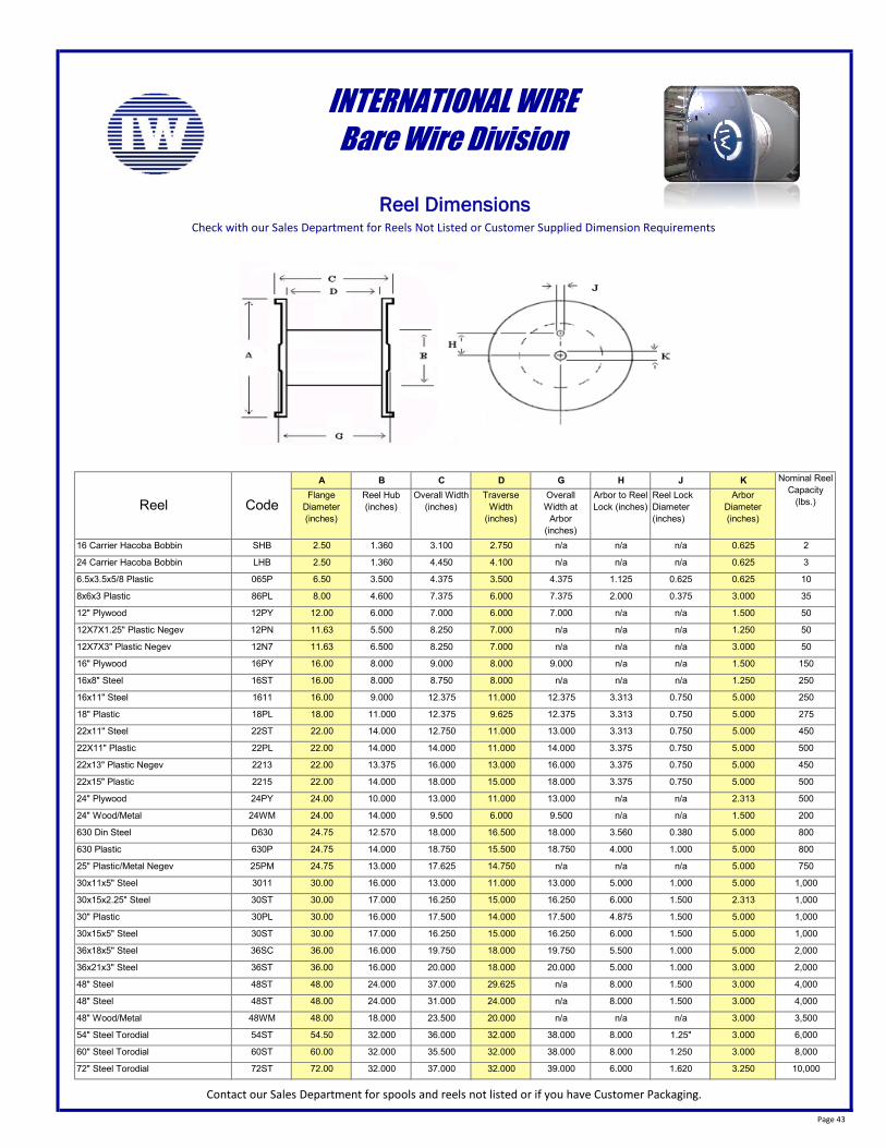
Page 43
A B C D G H J KFlange
Diameter (inches)
Reel Hub (inches)
Overall Width (inches)
Traverse Width
(inches)
OverallWidth at
Arbor (inches)
Arbor to Reel Lock (inches)
Reel Lock Diameter (inches)
Arbor Diameter (inches)
16 Carrier Hacoba Bobbin SHB 2.50 1.360 3.100 2.750 n/a n/a n/a 0.625 2
24 Carrier Hacoba Bobbin LHB 2.50 1.360 4.450 4.100 n/a n/a n/a 0.625 3
6.5x3.5x5/8 Plastic 065P 6.50 3.500 4.375 3.500 4.375 1.125 0.625 0.625 10
8x6x3 Plastic 86PL 8.00 4.600 7.375 6.000 7.375 2.000 0.375 3.000 35
12" Plywood 12PY 12.00 6.000 7.000 6.000 7.000 n/a n/a 1.500 50
12X7X1.25" Plastic Negev 12PN 11.63 5.500 8.250 7.000 n/a n/a n/a 1.250 50
12X7X3" Plastic Negev 12N7 11.63 6.500 8.250 7.000 n/a n/a n/a 3.000 50
16" Plywood 16PY 16.00 8.000 9.000 8.000 9.000 n/a n/a 1.500 150
16x8" Steel 16ST 16.00 8.000 8.750 8.000 n/a n/a n/a 1.250 250
16x11" Steel 1611 16.00 9.000 12.375 11.000 12.375 3.313 0.750 5.000 250
18" Plastic 18PL 18.00 11.000 12.375 9.625 12.375 3.313 0.750 5.000 275
22x11" Steel 22ST 22.00 14.000 12.750 11.000 13.000 3.313 0.750 5.000 450
22X11" Plastic 22PL 22.00 14.000 14.000 11.000 14.000 3.375 0.750 5.000 500
22x13" Plastic Negev 2213 22.00 13.375 16.000 13.000 16.000 3.375 0.750 5.000 450
22x15" Plastic 2215 22.00 14.000 18.000 15.000 18.000 3.375 0.750 5.000 500
24" Plywood 24PY 24.00 10.000 13.000 11.000 13.000 n/a n/a 2.313 500
24" Wood/Metal 24WM 24.00 14.000 9.500 6.000 9.500 n/a n/a 1.500 200
630 Din Steel D630 24.75 12.570 18.000 16.500 18.000 3.560 0.380 5.000 800
630 Plastic 630P 24.75 14.000 18.750 15.500 18.750 4.000 1.000 5.000 800
25" Plastic/Metal Negev 25PM 24.75 13.000 17.625 14.750 n/a n/a n/a 5.000 750
30x11x5" Steel 3011 30.00 16.000 13.000 11.000 13.000 5.000 1.000 5.000 1,000
30x15x2.25" Steel 30ST 30.00 17.000 16.250 15.000 16.250 6.000 1.500 2.313 1,000
30" Plastic 30PL 30.00 16.000 17.500 14.000 17.500 4.875 1.500 5.000 1,000
30x15x5" Steel 30ST 30.00 17.000 16.250 15.000 16.250 6.000 1.500 5.000 1,000
36x18x5" Steel 36SC 36.00 16.000 19.750 18.000 19.750 5.500 1.000 5.000 2,000
36x21x3" Steel 36ST 36.00 16.000 20.000 18.000 20.000 5.000 1.000 3.000 2,000
48" Steel 48ST 48.00 24.000 37.000 29.625 n/a 8.000 1.500 3.000 4,000
48" Steel 48ST 48.00 24.000 31.000 24.000 n/a 8.000 1.500 3.000 4,000
48" Wood/Metal 48WM 48.00 18.000 23.500 20.000 n/a n/a n/a 3.000 3,500
54" Steel Torodial 54ST 54.50 32.000 36.000 32.000 38.000 8.000 1.25" 3.000 6,000
60" Steel Torodial 60ST 60.00 32.000 35.500 32.000 38.000 8.000 1.250 3.000 8,000
72" Steel Torodial 72ST 72.00 32.000 37.000 32.000 39.000 6.000 1.620 3.250 10,000
Contact our Sales Department for spools and reels not listed or if you have Customer Packaging.
INTERNATIONAL WIREBare Wire Division
Reel DimensionsCheck with our Sales Department for Reels Not Listed or Customer Supplied Dimension Requirements
Nominal Reel Capacity
(lbs.)Reel Code
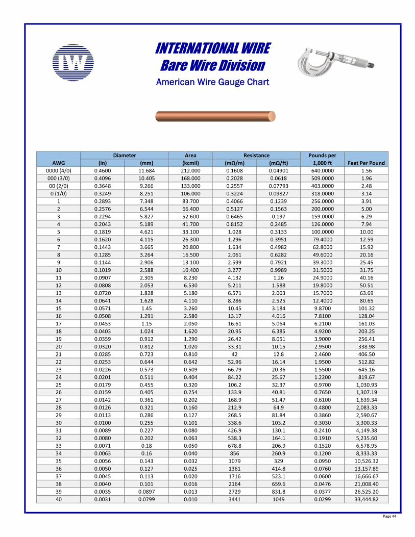
Page 44
Area(in) (mm) (kcmil) (mΩ/m) (mΩ/ft)
0000 (4/0) 0.4600 11.684 212.000 0.1608 0.04901 640.0000 1.56000 (3/0) 0.4096 10.405 168.000 0.2028 0.0618 509.0000 1.9600 (2/0) 0.3648 9.266 133.000 0.2557 0.07793 403.0000 2.480 (1/0) 0.3249 8.251 106.000 0.3224 0.09827 318.0000 3.14
1 0.2893 7.348 83.700 0.4066 0.1239 256.0000 3.912 0.2576 6.544 66.400 0.5127 0.1563 200.0000 5.003 0.2294 5.827 52.600 0.6465 0.197 159.0000 6.294 0.2043 5.189 41.700 0.8152 0.2485 126.0000 7.945 0.1819 4.621 33.100 1.028 0.3133 100.0000 10.006 0.1620 4.115 26.300 1.296 0.3951 79.4000 12.597 0.1443 3.665 20.800 1.634 0.4982 62.8000 15.928 0.1285 3.264 16.500 2.061 0.6282 49.6000 20.169 0.1144 2.906 13.100 2.599 0.7921 39.3000 25.45
10 0.1019 2.588 10.400 3.277 0.9989 31.5000 31.7511 0.0907 2.305 8.230 4.132 1.26 24.9000 40.1612 0.0808 2.053 6.530 5.211 1.588 19.8000 50.5113 0.0720 1.828 5.180 6.571 2.003 15.7000 63.6914 0.0641 1.628 4.110 8.286 2.525 12.4000 80.6515 0.0571 1.45 3.260 10.45 3.184 9.8700 101.3216 0.0508 1.291 2.580 13.17 4.016 7.8100 128.0417 0.0453 1.15 2.050 16.61 5.064 6.2100 161.0318 0.0403 1.024 1.620 20.95 6.385 4.9200 203.2519 0.0359 0.912 1.290 26.42 8.051 3.9000 256.4120 0.0320 0.812 1.020 33.31 10.15 2.9500 338.9821 0.0285 0.723 0.810 42 12.8 2.4600 406.5022 0.0253 0.644 0.642 52.96 16.14 1.9500 512.8223 0.0226 0.573 0.509 66.79 20.36 1.5500 645.1624 0.0201 0.511 0.404 84.22 25.67 1.2200 819.6725 0.0179 0.455 0.320 106.2 32.37 0.9700 1,030.9326 0.0159 0.405 0.254 133.9 40.81 0.7650 1,307.1927 0.0142 0.361 0.202 168.9 51.47 0.6100 1,639.3428 0.0126 0.321 0.160 212.9 64.9 0.4800 2,083.3329 0.0113 0.286 0.127 268.5 81.84 0.3860 2,590.6730 0.0100 0.255 0.101 338.6 103.2 0.3030 3,300.3331 0.0089 0.227 0.080 426.9 130.1 0.2410 4,149.3832 0.0080 0.202 0.063 538.3 164.1 0.1910 5,235.6033 0.0071 0.18 0.050 678.8 206.9 0.1520 6,578.9534 0.0063 0.16 0.040 856 260.9 0.1200 8,333.3335 0.0056 0.143 0.032 1079 329 0.0950 10,526.3236 0.0050 0.127 0.025 1361 414.8 0.0760 13,157.8937 0.0045 0.113 0.020 1716 523.1 0.0600 16,666.6738 0.0040 0.101 0.016 2164 659.6 0.0476 21,008.4039 0.0035 0.0897 0.013 2729 831.8 0.0377 26,525.2040 0.0031 0.0799 0.010 3441 1049 0.0299 33,444.82
INTERNATIONAL WIREBare Wire Division
American Wire Gauge Chart
DiameterFeet Per Pound
Resistance Pounds per 1,000 ftAWG

Page 45
INTERNATIONAL WIREBare Wire Division
Engineering Resources
Technical expertise
Troubleshooting at theCustomer or Jobsite
With decades of experience and technical expertise we know every nook and cranny of Wire and Cable
manufacturing — from providing cabling and harness solutions for top automotive makers to helping engineers
in mining operations, oil exploration and renewable energy, you will find us there.
Our vast Engineering resouces are available to provide you with the best solution to meet your wire and cable needs including: Custom Design
Contact our Sales Department to learn more.

Glossary of Terms & Conductor Information
for Wire & Cable
Alloy: A combination of a metal with one or more elements to form a new material with different properties. Attenuation: Weakening or reduction of the strength of a transmitted signal through a cable or circuit. It is also a measure of a cable’s efficiency to transmit a signal at a given frequency.Anneal: To subject a material to a heat treatment to remove the effects of cold work, lowering its tensile strength, rendering it softer with greater elongation.AWG (American Wire Gauge): A standard used to specify the physical size of a solid or stranded conductor primarily used in the United States. Originally called the Brown and Sharpe Gage.Bird-caging: A phenomenon that occurs during stranding or insulating where the conductor enters a restriction such as a die or extrusion tip. The outer layers of strands back-up, spread out, or otherwise separate away from the core strands. The problem has been attributed to poor stranding techniques and improper tensions during processing.Break Strength: The maximum load that a specimen attains when tested in tension to fracture.Bunch Construction: A stranded construction in which the individual strands are randomly laid and twisted in the same lay direction and same length of lay. The strands do not follow a geometric arrangement or pattern. Capacitance: A measure of a component’s opposition to a change of voltage in a circuit, specified in farads. Cast: The natural curvature of a wire when in an unrestrained state.CMA (Circular Mil Area): A measure of a round wire’s cross-sectional area, calculated by squaring the diameter (in mils) of a strand and multiplying the result by the number of strands. One circular mil (cmil) is equivalent to the area of a circle 0.001 inch in diameter, equal to 7.854 X 10⁻⁷ in2.Concentric Construction: A central wire surrounded by one or more layers of helically laid wires in a geometric pattern. Concentric constructions have 7, 19, 37, 61, etc. strands.Conductivity: The inverse of resistivity and a measure of a material’s ability to conduct electric current. It is usually compared to that of annealed copper, and is generally stated in terms of %IACS.Elongation: A measure of a material’s ability to stretch or elongate prior to fracture. It is expressed as a percentage (increase in length) over a specified gauge length (typically 10 inches for wire).Equilay Concentric: A central wire surrounded by one or more layers of helically laid wires in a geometric pattern, with alternately reversed lay direction and the same lay length.Flex Life (or Flex Fatigue Life): The number of cycles a sample can withstand when subjected to a repetitive stress or strain mode before failure.Flexibility: The capability of being bent when an external force is applied, its pliability or limberness. Low flexibility translates to being more rigid or stiff.Gauge (or Gage): A term used to designate the physical size of a wire or strand. Some definitions specify “Gage” as a size designation and “Gauge” as a measuring device (such as pressure gauge). These terms are often used interchangeably.Hard Drawn: A term referring to the temper of conductors that are drawn without annealing to the finish temper. IACS: International Annealed Copper StandardImpedance: The analog of resistance in an AC (alternating current) circuit. Impedance depends upon the resistance, inductance, capacitance and frequency of the circuit. The unit of impedance is the ohm.Inductance: A measure of a component’s opposition to a change in the current of a circuit, specified in henries. Inter-metallic Compound: Two or more metals with a chemical composition based on a definite atomic formula. Inter-metallics may have a fixed stoichiometric or a very narrow range of chemical composition.
Custom constructions are available, please contact our Sales Department The information provided on this page is for reference purposes only.
International Wire Group, Inc. • 12 Masonic Ave • Camden, N.Y. U.S.A. Phone: 315-245-2000 • Web: www.internationalwiregroup.com
Page 46
Lay Direction: The helical direction of the strands or members in any layer of a stranded construction. The two lay directions are usually denoted as “S” (left hand lay) or “Z” (right hand lay).Lay Factor: The ratio of the lay length to the external diameter of the corresponding layer of wires or members in the stranded conductor.Lay Length (length of lay): The axial length for one revolution of a strand or member in any layer of a stranded or rope stranded construction.MCM: An area unit equivalent to 1,000 circular mils. MCM may also be referred to as kcmil.Ohm: A unit of electrical resistance defined as the resistance necessary to produce 1 ampere of current to flow in a circuit with an applied potential of 1 volt.Plating Percentage: See Volume Percentage of Plating and Weight Percentage of Plating.Plating Thickness: The measured thickness of the plated coating on a wire strand. Measurements are usually in micro-inches (millionths of an inch) or microns (millionths of a meter).Polysulfide Testing: A test method that exposes a sample to a sodium polysulfide solution to qualitatively determine the continuity of the plating on a wire strand. The test method is specified in ASTM B 298 and B 355. Resistance: A measure of a component’s opposition to the flow of electric current, specified in ohms. Resistivity: The characteristic of a material to impede the flow of electrons (electrical current). It is the material’s electrical resistance for a unit volume. This value is specific to a material and not its geometry.Rope Construction: A conductor composed of separate stranded constructions that are then twisted into the final construction.Rope Member: A bunched or concentric stranded construction subsequently stranded again to form a rope construction.Stranding Factor: The increase in weight and electrical resistance of a conductor due to the lay length of the strands or members.Temperature Coefficient of Resistance: The change in a material’s electrical resistance (resistivity) due to a change of one degree in temperature. It is expressed in units per ºC (or units per ºF).Tensile Strength: The maximum longitudinal tensile stress that may be applied to a material without fracturing or rupturing, calculated to a reference unit (lbs/in2, kg/mm2, etc.) by dividing the breaking load by the cross-sectional area.Tensile Stress: Force per unit cross-sectional area applied to a material.True Concentric: A central wire surrounded by one or more layers of helically laid wires in a geometric pattern, with alternately reversed lay direction and increasing lay length.Tubular Strander: A type of twisting machine where the payoffs are located inside the tube and the take-up is external.Unidirectional Concentric: A central wire surrounded by one or more layers of helically laid wires in a geometric pattern, with the same lay direction and an increasing lay length.Unilay (Unidirectional Equilay Concentric): A central wire surrounded by one or more layers of helically laid wires in a geometric pattern, with the same lay direction and the same lay length.Volume Percentage of Plating: The ratio of the volume of the plated material to the total volume of the conductor.Weight Percentage of Plating: The ratio of the weight of the plated material to the total weight of the conductor. Conductor plating percentages usually refer to weight percentage when a distinction is not made.Weight per Unit Length: A method of specifying the weight of conductor or wire using a standard length. Common lengths of 1,000 feet or 1,000 meters are used, however other lengths may also be specified.
Glossary of Terms & Conductor Information
for Wire & Cable
Custom constructions are available, please contact our Sales Department The information provided on this page is for reference purposes only.
International Wire Group, Inc. • 12 Masonic Ave • Camden, N.Y. U.S.A. Phone: 315-245-2000 • Web: www.internationalwiregroup.com
Page 47
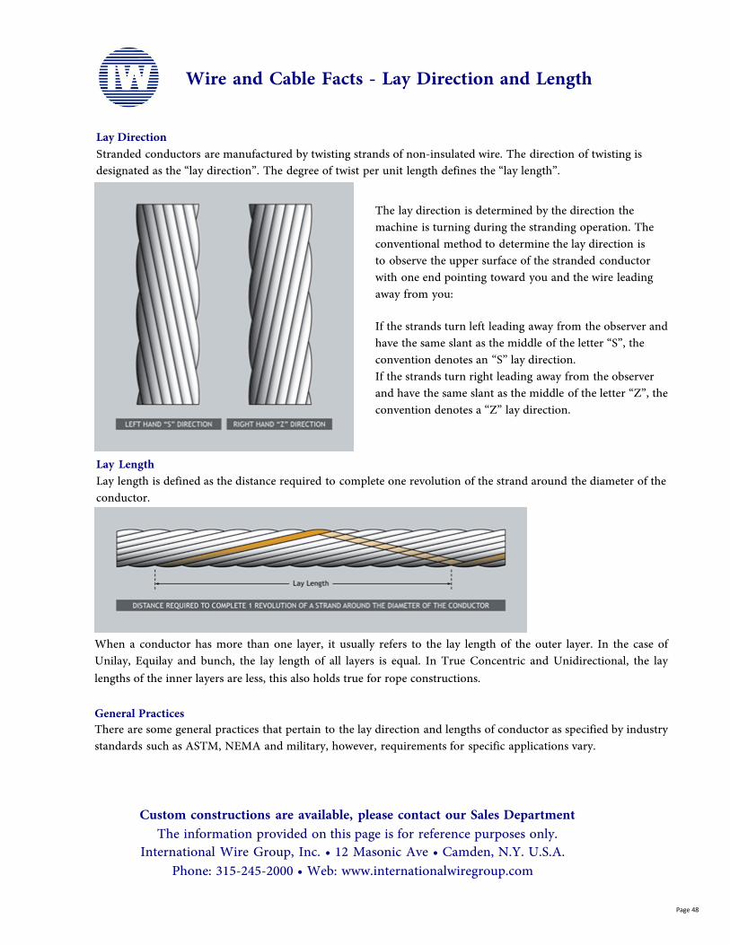
Wire and Cable Facts - Lay Direction and Length
Lay DirectionStranded conductors are manufactured by twisting strands of non-insulated wire. The direction of twisting is designated as the “lay direction”. The degree of twist per unit length defines the “lay length”.
The lay direction is determined by the direction the machine is turning during the stranding operation. The conventional method to determine the lay direction isto observe the upper surface of the stranded conductor with one end pointing toward you and the wire leading away from you:
If the strands turn left leading away from the observer and have the same slant as the middle of the letter “S”, the convention denotes an “S” lay direction.If the strands turn right leading away from the observer and have the same slant as the middle of the letter “Z”, the convention denotes a “Z” lay direction.
Lay LengthLay length is defined as the distance required to complete one revolution of the strand around the diameter of the conductor.
When a conductor has more than one layer, it usually refers to the lay length of the outer layer. In the case of Unilay, Equilay and bunch, the lay length of all layers is equal. In True Concentric and Unidirectional, the lay lengths of the inner layers are less, this also holds true for rope constructions.
General PracticesThere are some general practices that pertain to the lay direction and lengths of conductor as specified by industry standards such as ASTM, NEMA and military, however, requirements for specific applications vary.
Custom constructions are available, please contact our Sales Department The information provided on this page is for reference purposes only.
International Wire Group, Inc. • 12 Masonic Ave • Camden, N.Y. U.S.A. Phone: 315-245-2000 • Web: www.internationalwiregroup.com
Page 48
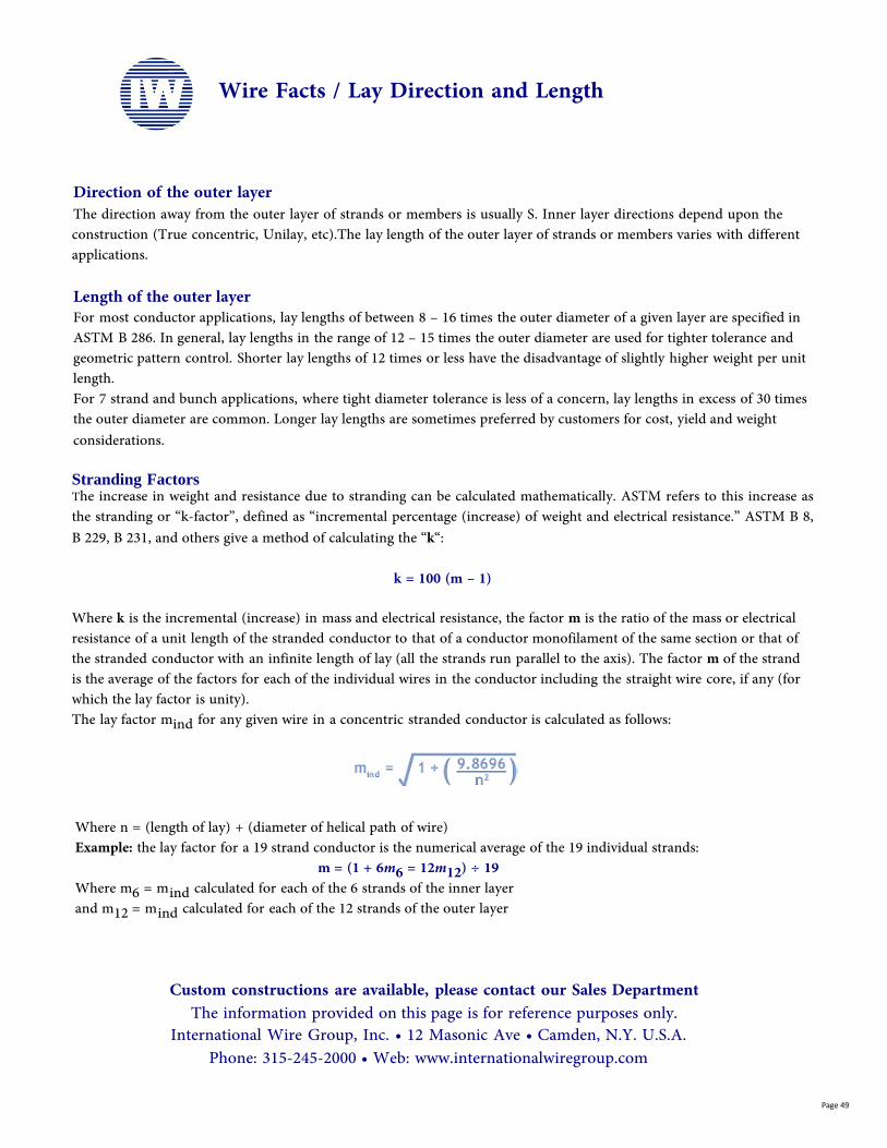
Wire Facts / Lay Direction and Length
Direction of the outer layer The direction away from the outer layer of strands or members is usually S. Inner layer directions depend upon the construction (True concentric, Unilay, etc).The lay length of the outer layer of strands or members varies with different applications.
Length of the outer layerFor most conductor applications, lay lengths of between 8 – 16 times the outer diameter of a given layer are specified in ASTM B 286. In general, lay lengths in the range of 12 – 15 times the outer diameter are used for tighter tolerance and geometric pattern control. Shorter lay lengths of 12 times or less have the disadvantage of slightly higher weight per unit length.For 7 strand and bunch applications, where tight diameter tolerance is less of a concern, lay lengths in excess of 30 times the outer diameter are common. Longer lay lengths are sometimes preferred by customers for cost, yield and weight considerations.
Stranding FactorsThe increase in weight and resistance due to stranding can be calculated mathematically. ASTM refers to this increase as the stranding or “k-factor”, defined as “incremental percentage (increase) of weight and electrical resistance.” ASTM B 8, B 229, B 231, and others give a method of calculating the “k“:
k = 100 (m – 1)
Where k is the incremental (increase) in mass and electrical resistance, the factor m is the ratio of the mass or electrical resistance of a unit length of the stranded conductor to that of a conductor monofilament of the same section or that of the stranded conductor with an infinite length of lay (all the strands run parallel to the axis). The factor m of the strand is the average of the factors for each of the individual wires in the conductor including the straight wire core, if any (for which the lay factor is unity).The lay factor mind for any given wire in a concentric stranded conductor is calculated as follows:
Where n = (length of lay) + (diameter of helical path of wire)Example: the lay factor for a 19 strand conductor is the numerical average of the 19 individual strands:
m = (1 + 6m6 = 12m12) ÷ 19Where m6 = mind calculated for each of the 6 strands of the inner layerand m12 = mind calculated for each of the 12 strands of the outer layer
Custom constructions are available, please contact our Sales Department The information provided on this page is for reference purposes only.
International Wire Group, Inc. • 12 Masonic Ave • Camden, N.Y. U.S.A. Phone: 315-245-2000 • Web: www.internationalwiregroup.com
Page 49

Wire and Cable Facts / Strand Configurations
Stranded conductors are composed of un-insulated strands of wire twisted together. The advantages of stranded conductor over a single strand of equal cross-section are increased flexibility and flex-fatigue life. Stranded conductor can be manufactured in a variety of configurations, the most common being concentric, bunched and ropes.ConcentricWhen the term “concentric stranding” is used, it refers to the definition of the word “concentric”, which is having a “common center”. Concentric conductor may be defined as:“A central wire (strand) surrounded by one or more layers of helically laid wires in a geometric pattern.” The geometric pattern requires that concentric constructions can only be produced with 7, 19, 37, 61, (etc.) strands or members, following the pattern that each successive layer has 6 more strands than the layer below it. In all types of concentric constructions, the geometric pattern of the strands is consistent for the entire length of the conductor. That is, the central strand, and the strands in each layer remain in their respective positions from the beginning to the end of its length.The main advantage of concentric constructions is the close/tight diameter tolerances that can be maintained on the conductor. Concentric constructions have very smooth uniform surfaces that are suited for thin wall insulation in high performance applications.Concentric StrandingThere are four common types of concentric constructions manufactured for the high performance wire and cable industry. Although there are 4 distinct types, the industry normally refers to “Concentric” as “True Concentric” and will use the terms interchangeably. The other types are referenced as noted.
Concentric or True Concentric characterized by a central wire surrounded by one or more layers of helically laid wires in a geometric pattern, with alternately reversed lay direction and increasing lay length.
Equilay or Equilay Concentric characterized by a central wire surrounded by one or more layers of helically laid wires in a geometric pattern, with alternately reversed lay direction and the same lay length.
Custom constructions are available, please contact our Sales Department The information provided on this page is for reference purposes only.
International Wire Group, Inc. • 12 Masonic Ave • Camden, N.Y. U.S.A. Phone: 315-245-2000 • Web: www.internationalwiregroup.com
Page 50
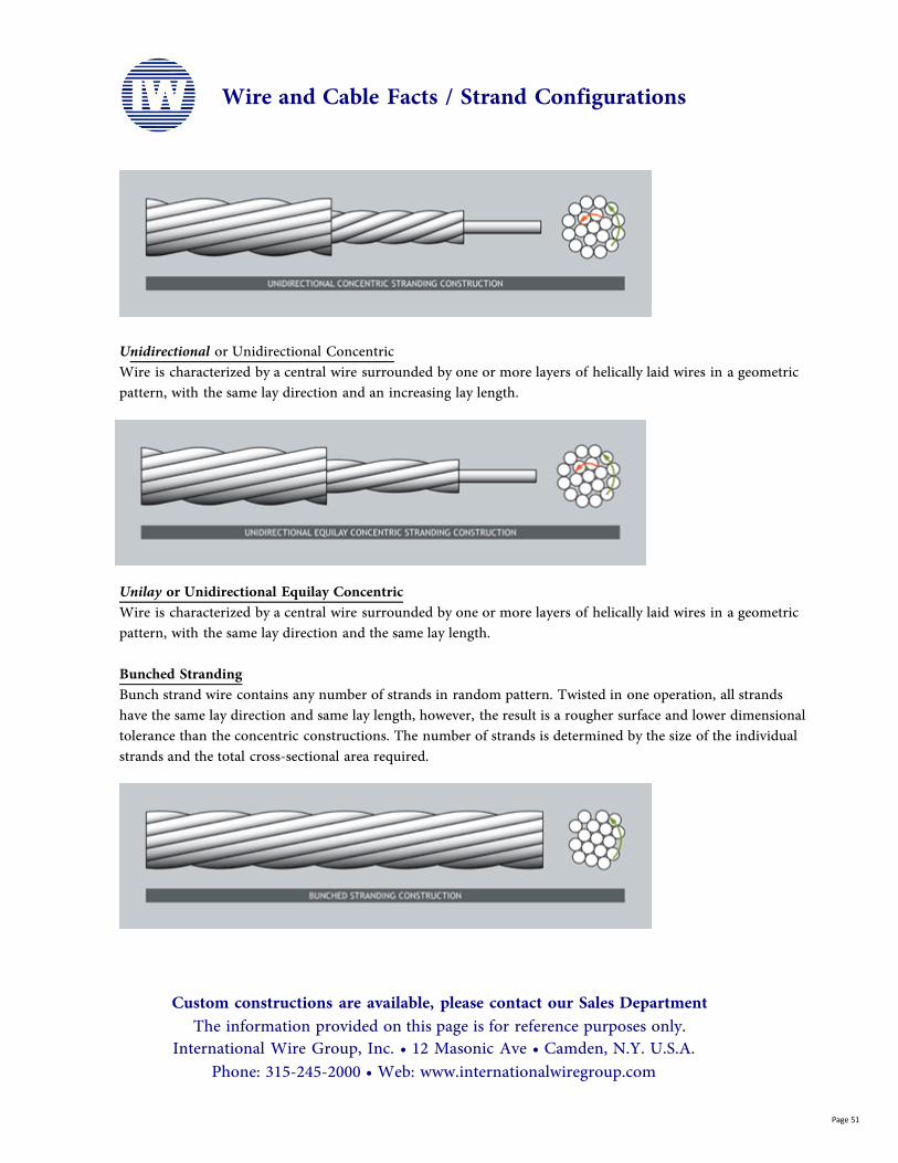
Unidirectional or Unidirectional Concentric Wire is characterized by a central wire surrounded by one or more layers of helically laid wires in a geometric pattern, with the same lay direction and an increasing lay length.
Unilay or Unidirectional Equilay Concentric Wire is characterized by a central wire surrounded by one or more layers of helically laid wires in a geometric pattern, with the same lay direction and the same lay length.
Bunched StrandingBunch strand wire contains any number of strands in random pattern. Twisted in one operation, all strands have the same lay direction and same lay length, however, the result is a rougher surface and lower dimensional tolerance than the concentric constructions. The number of strands is determined by the size of the individual strands and the total cross-sectional area required.
Wire and Cable Facts / Strand Configurations
Custom constructions are available, please contact our Sales Department The information provided on this page is for reference purposes only.
International Wire Group, Inc. • 12 Masonic Ave • Camden, N.Y. U.S.A. Phone: 315-245-2000 • Web: www.internationalwiregroup.com
Page 51
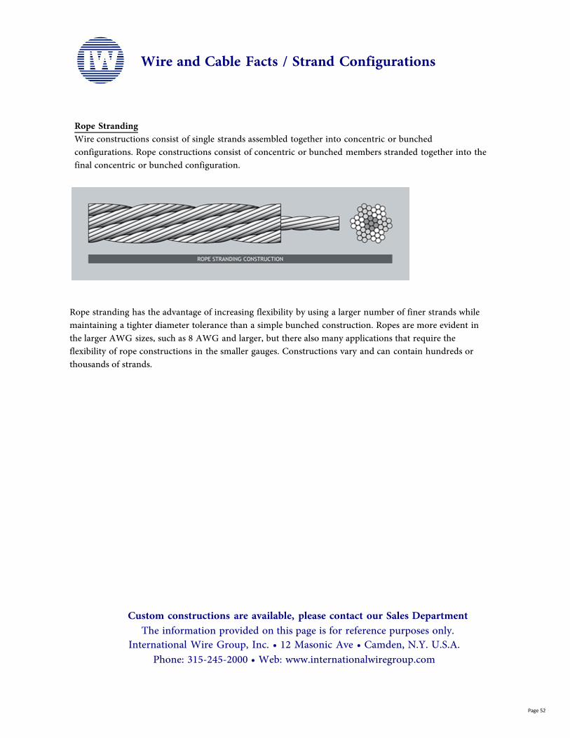
Rope StrandingWire constructions consist of single strands assembled together into concentric or bunched configurations. Rope constructions consist of concentric or bunched members stranded together into the final concentric or bunched configuration.
Rope stranding has the advantage of increasing flexibility by using a larger number of finer strands while maintaining a tighter diameter tolerance than a simple bunched construction. Ropes are more evident in the larger AWG sizes, such as 8 AWG and larger, but there also many applications that require the flexibility of rope constructions in the smaller gauges. Constructions vary and can contain hundreds or thousands of strands.
Custom constructions are available, please contact our Sales Department The information provided on this page is for reference purposes only.
International Wire Group, Inc. • 12 Masonic Ave • Camden, N.Y. U.S.A. Phone: 315-245-2000 • Web: www.internationalwiregroup.com
Wire and Cable Facts / Strand Configurations
Page 52

At IWG, we are more than wire...
Safety First, Quality Always
Integrity Leadership Innovation Relationships
The safety of our employees is at the core of everything we do. People are the resource of our success.
Leadership and excellence in performance
are sought and rewarded. As
an Organization we continually
strive to improve our
performance.
Our products and services
reflect dedication to quality,
innovation and value.
Teamwork
We treat one another with
respect, promote teamwork, and
encourage personal freedom
and growth.
Customers are the reason we
exist. Its is through our
talent, passion and
commitment that we strive to
exceed their expectations.
Our conduct demonstrates integrity and
commitment to ethics, safety, health and the environment.
Our Core Values
We are people! Our proud, skilled, and diverse workforceis the heart of IWG.
are our guiding principals.