Embed Size (px)
Citation preview
Claus Kuhnel
BASCOM
Programming ofMicrocontrollers with Ease
An Introductionby Program Examples
BASCOM Programming of Microcontrollers with Ease: An Introduction by Program Examples
Copyright © 2001 Claus Kuhnel
All rights reserved. No part of this work may be reproduced in any form except by written permission of the author.
All rights of translation reserved.
Publisher and author assume no responsibility for any errors that may arise from the use of devices and software described in this
book.
Universal Publishers/uPUBLISH.com USA � 2001
ISBN: 1-58112-671-9
www.upublish.com/books/kuhnel.htm
3
PrefaceThe microcontroller market knows some well introduced 8-bit micro-controller families like Intel's 8051 with its many derivatives fromdifferent manufacturers, Motorola's 6805 and 68HC11, Microchip'sPICmicros and Atmel's AVR.
The 8051 microcontroller family has been well-known over manyyears. The development of new derivatives is not finished yet. Fromtime to time new powerful derivatives are announced.
You will find derivatives from Philips, Dallas, Analog Devices andCygnal and others with the known 8051 core but enhanced clock andperipherals. For example, complete analog-to-digital and digital-to-analog subsystems were integrated in some chips.
Atmel developed the AVR microcontroller family which is well suitedfor high-level language programming and in-system programming.
For all those microcontrollers there is development software rangingfrom simple assemblers for DOS to integrated development envi-ronments for Windows95/98/NT on the market.
Apart from programming environments as they are offered, for ex-ample, by KEIL, IAR or E-LAB Computer for professional applica-tions, also the more economical and nonetheless sufficientlyequipped development environments can maintain ground.
BASCOM-8051 and BASCOM-AVR are development environmentsbuilt around a powerful BASIC compiler which is suited for projecthandling and program development for the 8051 family and its de-rivatives as well as for the AVR microcontrollers from Atmel.
The programming of microcontrollers using BASCOM-8051 (version2.0.4.0) and BASCOM-AVR (version 1.11.3.0) will be described inthis book.
Some applications help understand the usage of BASCOM-8051 andBASCOM-AVR.
4
Acknowledgement
I should like to thank the following:
• in the first place, Mark Alberts of MCS Electronics, who developedthe BASCOM programming environment at an outstanding price-performance ratio,
• Atmel for the development of the AVR RISC microcontrollerswhich introduced new capabilities into the microcontroller families,
• Christer Johansson of High Tech Horizon, who supports safecommunication of microcontrollers and PC by the developmentand free distribution of the S.N.A.P. protocol and the necessarytools effectively and
• Lars Wictorsson of LAWICEL for the development of theCANDIPs, microcontroller modules with CAN interface.
5
Contents1 Supported Microcontrollers ............................................................. 9
1.1 8051 Family .............................................................................. 9
1.2 AVR Family............................................................................. 11
2 BASCOM....................................................................................... 23
2.1 BASCOM Demos.................................................................... 23
2.2 BASCOM Commercial Versions............................................. 25
2.3 Update of BASCOM Commercial Versions ............................ 25
2.4 BASCOM Projects .................................................................. 27
2.4.1 Working on Projects ........................................................ 27
2.4.2 BASCOM Options ............................................................ 28
2.5 BASCOM Tools ...................................................................... 37
2.5.1 Simulation ........................................................................ 37
2.5.2 Terminal Emulator ........................................................... 40
2.5.3 LCD Designer .................................................................. 42
2.5.4 Library Manager............................................................... 46
2.5.5 Programming Devices ..................................................... 50
2.6 Hardware for AVR RISC Microcontroller ................................ 55
2.6.1 DT006 AVR Development Board..................................... 55
2.6.2 AVR-ALPHA with AT90S2313 ......................................... 56
2.7 Instead of "Hello World".......................................................... 57
2.7.1 AVR.................................................................................. 57
2.7.2 8051 ................................................................................. 58
2.7.3 Things in Common........................................................... 59
2.7.4 Simulation ........................................................................ 64
2.8 BASCOM Help System........................................................... 67
3 Some BASCOM Internals ............................................................. 69
3.1 Building new instructions ........................................................ 69
6
3.2 Parameters for Subroutines in BASCOM-AVR....................... 71
3.3 BASIC & Assembler................................................................ 73
3.3.1 AVR.................................................................................. 74
3.3.2 8051 ................................................................................. 75
4 Applications ................................................................................... 77
4.1 Programmable Logic............................................................... 77
4.2 Timer and Counter.................................................................. 81
4.2.1 AVR.................................................................................. 81
4.2.2 8051 ............................................................................... 104
4.3 LED Control .......................................................................... 107
4.3.1 Single LED ..................................................................... 107
4.3.2 Seven-Segment Displays............................................... 108
4.3.3 Dot-Matrix Displays ........................................................ 114
4.4 LCD Control .......................................................................... 119
4.4.1 Direct Control ................................................................. 119
4.4.2 LCD with Serial Interface ............................................... 122
4.5 Connecting Keys and Keyboards.......................................... 128
4.5.1 Single Keys .................................................................... 129
4.5.2 Matrix Keypad ................................................................ 132
4.5.3 PC-AT Keyboard ............................................................ 136
4.6 Data Input by IR Remote Control.......................................... 140
4.7 Asynchronous Serial Communication................................... 143
4.8 1-WIRE Interface .................................................................. 151
4.9 SPI Interface ......................................................................... 161
4.10 I2C Bus................................................................................ 167
4.11 Scalable Network Protocol S.N.A.P.................................... 173
4.11.1 S.N.A.P. Features ........................................................ 174
4.11.2 Description of S.N.A.P. Protocol .................................. 175
4.11.3 S.N.A.P. Monitor........................................................... 179
4.11.4 Digital I/O...................................................................... 183
7
4.12 CANDIP - Interface to CAN ................................................ 197
4.13 Random Numbers .............................................................. 209
4.14 Moving Average.................................................................. 214
5 Appendix ..................................................................................... 219
5.1 Decimal-Hex-ASCII Converter.............................................. 219
5.2 DT006 Circuit Diagram......................................................... 220
5.3 Characters in Seven-Segment Display................................. 222
5.4 BASIC Stamp II .................................................................... 223
5.5 Literature .............................................................................. 224
5.6 Links ..................................................................................... 225
6 Index ........................................................................................... 231

8
9
1 Supported MicrocontrollersBASCOM is an Integrated Development Environment (IDE) that sup-ports the 8051 family of microcontrollers and some derivatives aswell as Atmel's AVR microcontrollers. Two products are available forthe various microcontrollers - BASCOM-8051 and BASCOM-AVR.
In a microcontroller project one needs to know the hardware base,i.e. the microcontroller with internal and connected peripherals, andthe software used, i.e. IDE handling, programming and debugging.
In this first chapter, let's have a look at the supported microcontrol-lers. A general overview will be given only; the various parts aredocumented by the manufacturers in more detail. You may alsosearch the web for more information and documentation on all themicrocontrollers dealt with here.
1.1 8051 FamilyThe 8051 is an accumulator-based microcontroller featuring 255instructions. A basic instruction cycle takes 12 clocks; however,some manufacturers redesigned the instruction-execution circuitry toreduce the instruction cycle.
The CPU has four banks of eight 8-bit registers in on-chip RAM forcontext switching. These registers reside within the 8051's lower 128bytes of RAM along with a bit-operation area and scratchpad RAM.These lower bytes can be addressed directly or indirectly by using an8-bit value. The upper 128 bytes of on-chip data RAM encompasstwo overlapping address spaces. One space is for directly addressedspecial-function registers (SFRs); the other space is for indirectlyaddressed RAM or stack. The SFRs define peripheral operations andconfigurations. The 8051 also has 16 bit-addressable bytes of on-chip RAM for flags or variables.
Without external circuitry, the maximum address range of all 8051processors is 64 Kbytes of program memory and 64 Kbytes of datamemory. External means can be made use of to increase this ad-dress space.
Register indirection uses an 8-bit register for an on-chip RAM ad-dress; an off-chip address requires an 8- or 16-bit data-pointer reg-ister (DPTR). The original 8051 has only one DPTR. Derivatives fromAtmel, Dallas, and Philips have two DPTRs. Siemens microcontrol-
10
lers have eight DPTRs. The 8051 microcontroller has bidirectionaland individually addressable I/O lines.
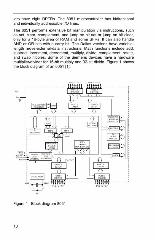
The 8051 performs extensive bit manipulation via instructions, suchas set, clear, complement, and jump on bit set or jump on bit clear,only for a 16-byte area of RAM and some SFRs. It can also handleAND or OR bits with a carry bit. The Dallas versions have variable-length move-external-data instructions. Math functions include add,subtract, increment, decrement, multiply, divide, complement, rotate,and swap nibbles. Some of the Siemens devices have a hardwaremultiplier/divider for 16-bit multiply and 32-bit divide. Figure 1 showsthe block diagram of an 8051 [1].
Figure 1 Block diagram 8051
11
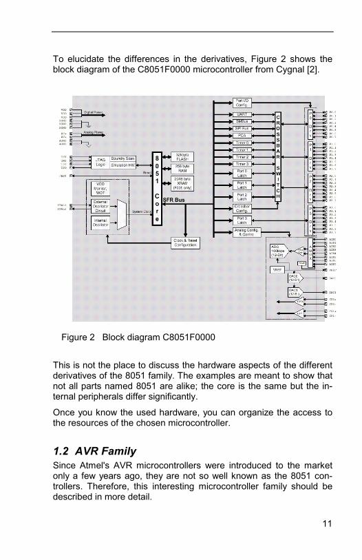
To elucidate the differences in the derivatives, Figure 2 shows theblock diagram of the C8051F0000 microcontroller from Cygnal [2].
This is not the place to discuss the hardware aspects of the differentderivatives of the 8051 family. The examples are meant to show thatnot all parts named 8051 are alike; the core is the same but the in-ternal peripherals differ significantly.
Once you know the used hardware, you can organize the access tothe resources of the chosen microcontroller.
1.2 AVR FamilySince Atmel's AVR microcontrollers were introduced to the marketonly a few years ago, they are not so well known as the 8051 con-trollers. Therefore, this interesting microcontroller family should bedescribed in more detail.
Figure 2 Block diagram C8051F0000
12
Atmel's AVR microcontrollers use a new RISC architecture which hasbeen developed to take advantage of the semiconductor integrationand software capabilities of the 1990's. The resulting microcontrollersoffer the highest MIPS/mW capability available in the 8-bit microcon-trollers market today.
The architecture of the AVR microcontrollers was designed togetherwith C-language experts to ensure that the hardware and softwarework hand-in-hand to develop a highly efficient, high-performancecode.
To optimize the code size, performance and power consumption,AVR microcontrollers have big register files and fast one-cycle in-structions.
The family of AVR microcontrollers includes differently equippedcontrollers - from a simple 8-pin microcontroller up to a high-endmicrocontroller with a large internal memory. The Harvard architec-ture addresses memories up to 8 MB directly. The register file is"dual mapped" and can be addressed as part of the on-chip SRAM,whereby fast context switches are possible.
All AVR microcontrollers are based on Atmel's low-power nonvolatileCMOS technology. The on-chip in-system programmable (ISP),downloadable flash memory permits devices on the user's circuitboard to be reprogrammed via SPI or with the help of a conventionalprogramming device.
By combining the efficient architecture with the downloadable flashmemory on the same chip, the AVR microcontrollers represent anefficient approach to applications in the "Embedded Controller" mar-ket.
Table 1 shows an overview of the devices available today, includingthe configuration of the internal memory and I/O. Further informationcan be found on Atmel's web site [http://www.atmel.com] and in theliterature [3].
13
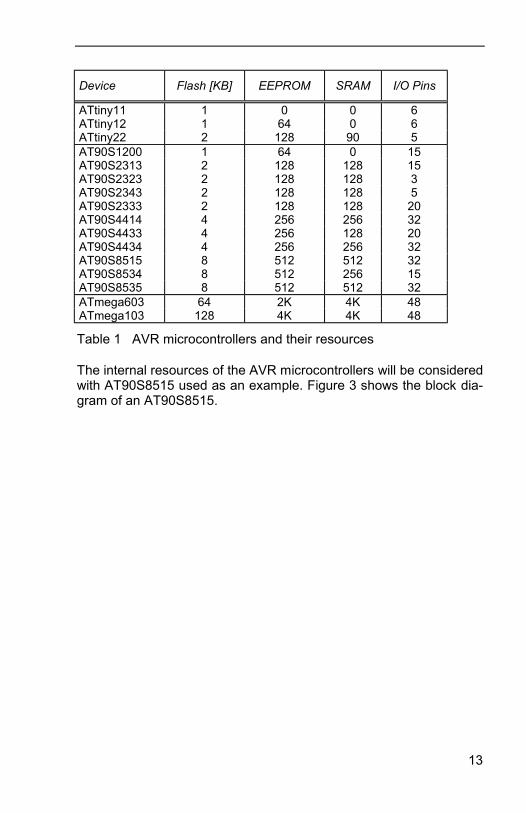
Table 1 AVR microcontrollers and their resources
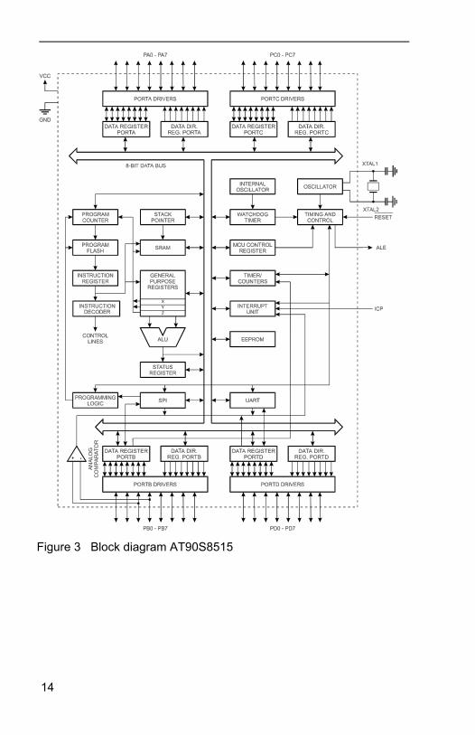
The internal resources of the AVR microcontrollers will be consideredwith AT90S8515 used as an example. Figure 3 shows the block dia-gram of an AT90S8515.
Device Flash [KB] EEPROM SRAM I/O Pins
ATtiny11 1 0 0 6ATtiny12 1 64 0 6ATtiny22 2 128 90 5AT90S1200 1 64 0 15AT90S2313 2 128 128 15AT90S2323 2 128 128 3AT90S2343 2 128 128 5AT90S2333 2 128 128 20AT90S4414 4 256 256 32AT90S4433 4 256 128 20AT90S4434 4 256 256 32AT90S8515 8 512 512 32AT90S8534 8 512 256 15AT90S8535 8 512 512 32ATmega603 64 2K 4K 48ATmega103 128 4K 4K 48
14
Figure 3 Block diagram AT90S8515
15
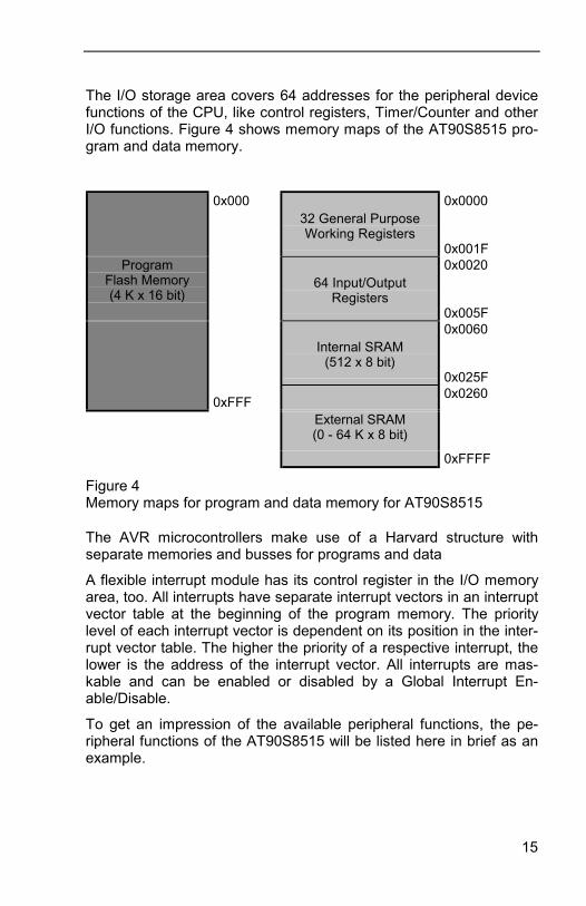
The I/O storage area covers 64 addresses for the peripheral devicefunctions of the CPU, like control registers, Timer/Counter and otherI/O functions. Figure 4 shows memory maps of the AT90S8515 pro-gram and data memory.
Figure 4Memory maps for program and data memory for AT90S8515
The AVR microcontrollers make use of a Harvard structure withseparate memories and busses for programs and data
A flexible interrupt module has its control register in the I/O memoryarea, too. All interrupts have separate interrupt vectors in an interruptvector table at the beginning of the program memory. The prioritylevel of each interrupt vector is dependent on its position in the inter-rupt vector table. The higher the priority of a respective interrupt, thelower is the address of the interrupt vector. All interrupts are mas-kable and can be enabled or disabled by a Global Interrupt En-able/Disable.
To get an impression of the available peripheral functions, the pe-ripheral functions of the AT90S8515 will be listed here in brief as anexample.
0x00032 General PurposeWorking Registers
0x0000
0x001FProgram
Flash Memory(4 K x 16 bit)
64 Input/OutputRegisters
0x0020
0x005F
Internal SRAM(512 x 8 bit)
0x0060
0x025F
0xFFF0x0260
External SRAM(0 - 64 K x 8 bit)
0xFFFF
16
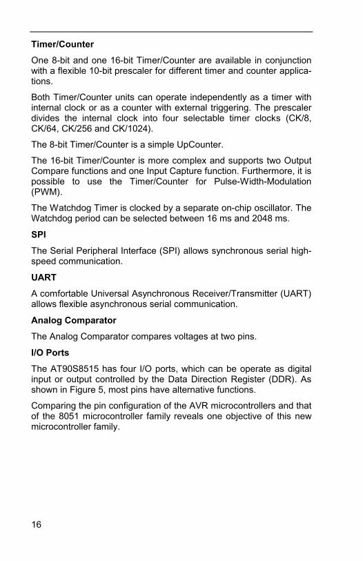
Timer/Counter
One 8-bit and one 16-bit Timer/Counter are available in conjunctionwith a flexible 10-bit prescaler for different timer and counter applica-tions.
Both Timer/Counter units can operate independently as a timer withinternal clock or as a counter with external triggering. The prescalerdivides the internal clock into four selectable timer clocks (CK/8,CK/64, CK/256 and CK/1024).
The 8-bit Timer/Counter is a simple UpCounter.
The 16-bit Timer/Counter is more complex and supports two OutputCompare functions and one Input Capture function. Furthermore, it ispossible to use the Timer/Counter for Pulse-Width-Modulation(PWM).
The Watchdog Timer is clocked by a separate on-chip oscillator. TheWatchdog period can be selected between 16 ms and 2048 ms.
SPI
The Serial Peripheral Interface (SPI) allows synchronous serial high-speed communication.
UART
A comfortable Universal Asynchronous Receiver/Transmitter (UART)allows flexible asynchronous serial communication.
Analog Comparator
The Analog Comparator compares voltages at two pins.
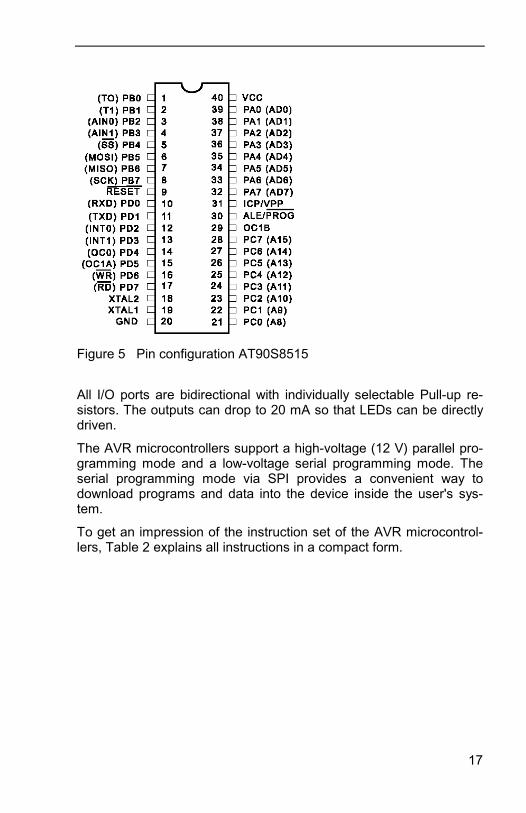
I/O Ports
The AT90S8515 has four I/O ports, which can be operate as digitalinput or output controlled by the Data Direction Register (DDR). Asshown in Figure 5, most pins have alternative functions.
Comparing the pin configuration of the AVR microcontrollers and thatof the 8051 microcontroller family reveals one objective of this newmicrocontroller family.
17
All I/O ports are bidirectional with individually selectable Pull-up re-sistors. The outputs can drop to 20 mA so that LEDs can be directlydriven.
The AVR microcontrollers support a high-voltage (12 V) parallel pro-gramming mode and a low-voltage serial programming mode. Theserial programming mode via SPI provides a convenient way todownload programs and data into the device inside the user's sys-tem.
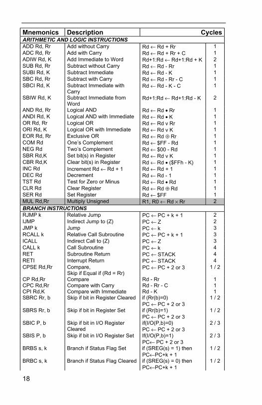
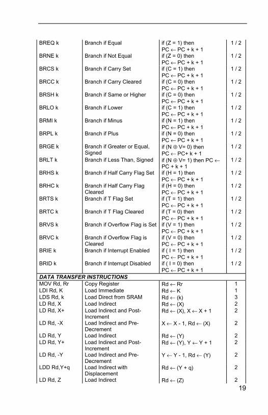
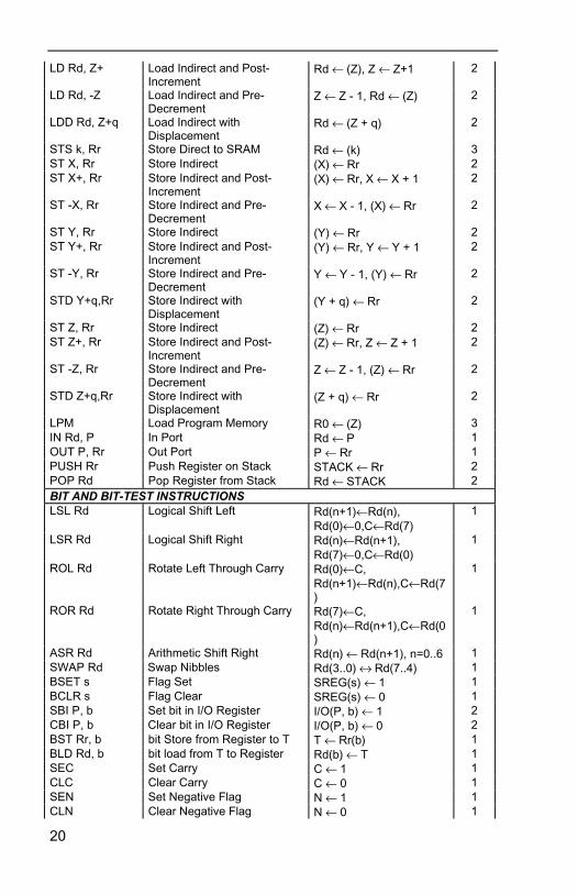
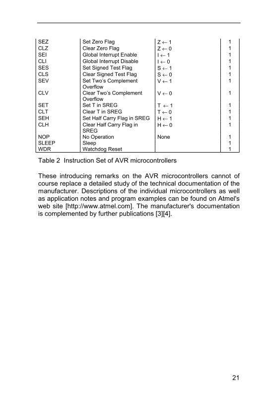
To get an impression of the instruction set of the AVR microcontrol-lers, Table 2 explains all instructions in a compact form.
Figure 5 Pin configuration AT90S8515
18
Mnemonics Description CyclesARITHMETIC AND LOGIC INSTRUCTIONSADD Rd, Rr Add without Carry Rd ← Rd + Rr 1ADC Rd, Rr Add with Carry Rd ← Rd + Rr + C 1ADIW Rd, K Add Immediate to Word Rd+1:Rd ← Rd+1:Rd + K 2SUB Rd, Rr Subtract without Carry Rd ← Rd - Rr 1SUBI Rd, K Subtract Immediate Rd ← Rd - K 1SBC Rd, Rr Subtract with Carry Rd ← Rd - Rr - C 1SBCI Rd, K Subtract Immediate with
CarryRd ← Rd - K - C 1
SBIW Rd, K Subtract Immediate fromWord
Rd+1:Rd ← Rd+1:Rd - K 2
AND Rd, Rr Logical AND Rd ← Rd • Rr 1ANDI Rd, K Logical AND with Immediate Rd ← Rd • K 1OR Rd, Rr Logical OR Rd ← Rd v Rr 1ORI Rd, K Logical OR with Immediate Rd ← Rd v K 1EOR Rd, Rr Exclusive OR Rd ← Rd ⊕ Rr 1COM Rd One’s Complement Rd ← $FF - Rd 1NEG Rd Two’s Complement Rd ← $00 - Rd 1SBR Rd,K Set bit(s) in Register Rd ← Rd v K 1CBR Rd,K Clear bit(s) in Register Rd ← Rd • ($FFh - K) 1INC Rd Increment Rd ← Rd + 1 Rd ← Rd + 1 1DEC Rd Decrement Rd ← Rd - 1 1TST Rd Test for Zero or Minus Rd ← Rd • Rd 1CLR Rd Clear Register Rd ← Rd ⊕ Rd 1SER Rd Set Register Rd ← $FF 1MUL Rd,Rr Multiply Unsigned R1, R0 ← Rd × Rr 2BRANCH INSTRUCTIONSRJMP k Relative Jump PC ← PC + k + 1 2IJMP Indirect Jump to (Z) PC ← Z 2JMP k Jump PC ← k 3RCALL k Relative Call Subroutine PC ← PC + k + 1 3ICALL Indirect Call to (Z) PC ← Z 3CALL k Call Subroutine PC ← k 4RET Subroutine Return PC ← STACK 4RETI Interrupt Return PC ← STACK 4CPSE Rd,Rr Compare,
Skip if Equal if (Rd = Rr)PC ← PC + 2 or 3 1 / 2
CP Rd,Rr Compare Rd - Rr 1CPC Rd,Rr Compare with Carry Rd - Rr - C 1CPI Rd,K Compare with Immediate Rd - K 1SBRC Rr, b Skip if bit in Register Cleared if (Rr(b)=0)
PC ← PC + 2 or 31 / 2
SBRS Rr, b Skip if bit in Register Set if (Rr(b)=1)PC ← PC + 2 or 3
1 / 2
SBIC P, b Skip if bit in I/O RegisterCleared
if(I/O(P,b)=0)PC ← PC + 2 or 3
2 / 3
SBIS P, b Skip if bit in I/O Register Set If(I/O(P,b)=1)PC← PC + 2 or 3
2 / 3
BRBS s, k Branch if Status Flag Set if (SREG(s) = 1) thenPC←PC+k + 1
1 / 2
BRBC s, k Branch if Status Flag Cleared if (SREG(s) = 0) thenPC←PC+k + 1
1 / 2
19
BREQ k Branch if Equal if (Z = 1) thenPC ← PC + k + 1
1 / 2
BRNE k Branch if Not Equal if (Z = 0) thenPC ← PC + k + 1
1 / 2
BRCS k Branch if Carry Set if (C = 1) thenPC ← PC + k + 1
1 / 2
BRCC k Branch if Carry Cleared if (C = 0) thenPC ← PC + k + 1
1 / 2
BRSH k Branch if Same or Higher if (C = 0) thenPC ← PC + k + 1
1 / 2
BRLO k Branch if Lower if (C = 1) thenPC ← PC + k + 1
1 / 2
BRMI k Branch if Minus if (N = 1) thenPC ← PC + k + 1
1 / 2
BRPL k Branch if Plus if (N = 0) thenPC ← PC + k + 1
1 / 2
BRGE k Branch if Greater or Equal,Signed
if (N ⊕ V= 0) thenPC ← PC+ k + 1
1 / 2
BRLT k Branch if Less Than, Signed if (N ⊕ V= 1) then PC ←PC + k + 1
1 / 2
BRHS k Branch if Half Carry Flag Set if (H = 1) thenPC ← PC + k + 1
1 / 2
BRHC k Branch if Half Carry FlagCleared
if (H = 0) thenPC ← PC + k + 1
1 / 2
BRTS k Branch if T Flag Set if (T = 1) thenPC ← PC + k + 1
1 / 2
BRTC k Branch if T Flag Cleared if (T = 0) thenPC ← PC + k + 1
1 / 2
BRVS k Branch if Overflow Flag is Set if (V = 1) thenPC ← PC + k + 1
1 / 2
BRVC k Branch if Overflow Flag isCleared
if (V = 0) thenPC ← PC + k + 1
1 / 2
BRIE k Branch if Interrupt Enabled if ( I = 1) thenPC ← PC + k + 1
1 / 2
BRID k Branch if Interrupt Disabled if ( I = 0) thenPC ← PC + k + 1
1 / 2
DATA TRANSFER INSTRUCTIONSMOV Rd, Rr Copy Register Rd ← Rr 1LDI Rd, K Load Immediate Rd ← K 1LDS Rd, k Load Direct from SRAM Rd ← (k) 3LD Rd, X Load Indirect Rd ← (X) 2LD Rd, X+ Load Indirect and Post-
IncrementRd ← (X), X ← X + 1 2
LD Rd, -X Load Indirect and Pre-Decrement
X ← X - 1, Rd ← (X) 2
LD Rd, Y Load Indirect Rd ← (Y) 2LD Rd, Y+ Load Indirect and Post-
IncrementRd ← (Y), Y ← Y + 1 2
LD Rd, -Y Load Indirect and Pre-Decrement
Y ← Y - 1, Rd ← (Y) 2
LDD Rd,Y+q Load Indirect withDisplacement
Rd ← (Y + q) 2
LD Rd, Z Load Indirect Rd ← (Z) 2
20
LD Rd, Z+ Load Indirect and Post-Increment
Rd ← (Z), Z ← Z+1 2
LD Rd, -Z Load Indirect and Pre-Decrement
Z ← Z - 1, Rd ← (Z) 2
LDD Rd, Z+q Load Indirect withDisplacement
Rd ← (Z + q) 2
STS k, Rr Store Direct to SRAM Rd ← (k) 3ST X, Rr Store Indirect (X) ← Rr 2ST X+, Rr Store Indirect and Post-
Increment(X) ← Rr, X ← X + 1 2
ST -X, Rr Store Indirect and Pre-Decrement
X ← X - 1, (X) ← Rr 2
ST Y, Rr Store Indirect (Y) ← Rr 2ST Y+, Rr Store Indirect and Post-
Increment(Y) ← Rr, Y ← Y + 1 2
ST -Y, Rr Store Indirect and Pre-Decrement
Y ← Y - 1, (Y) ← Rr 2
STD Y+q,Rr Store Indirect withDisplacement
(Y + q) ← Rr 2
ST Z, Rr Store Indirect (Z) ← Rr 2ST Z+, Rr Store Indirect and Post-
Increment(Z) ← Rr, Z ← Z + 1 2
ST -Z, Rr Store Indirect and Pre-Decrement
Z ← Z - 1, (Z) ← Rr 2
STD Z+q,Rr Store Indirect withDisplacement
(Z + q) ← Rr 2
LPM Load Program Memory R0 ← (Z) 3IN Rd, P In Port Rd ← P 1OUT P, Rr Out Port P ← Rr 1PUSH Rr Push Register on Stack STACK ← Rr 2POP Rd Pop Register from Stack Rd ← STACK 2BIT AND BIT-TEST INSTRUCTIONSLSL Rd Logical Shift Left Rd(n+1)←Rd(n),
Rd(0)←0,C←Rd(7)1
LSR Rd Logical Shift Right Rd(n)←Rd(n+1),Rd(7)←0,C←Rd(0)
1
ROL Rd Rotate Left Through Carry Rd(0)←C,Rd(n+1)←Rd(n),C←Rd(7)
1
ROR Rd Rotate Right Through Carry Rd(7)←C,Rd(n)←Rd(n+1),C←Rd(0)
1
ASR Rd Arithmetic Shift Right Rd(n) ← Rd(n+1), n=0..6 1SWAP Rd Swap Nibbles Rd(3..0) ↔ Rd(7..4) 1BSET s Flag Set SREG(s) ← 1 1BCLR s Flag Clear SREG(s) ← 0 1SBI P, b Set bit in I/O Register I/O(P, b) ← 1 2CBI P, b Clear bit in I/O Register I/O(P, b) ← 0 2BST Rr, b bit Store from Register to T T ← Rr(b) 1BLD Rd, b bit load from T to Register Rd(b) ← T 1SEC Set Carry C ← 1 1CLC Clear Carry C ← 0 1SEN Set Negative Flag N ← 1 1CLN Clear Negative Flag N ← 0 1
21
SEZ Set Zero Flag Z ← 1 1CLZ Clear Zero Flag Z ← 0 1SEI Global Interrupt Enable I ← 1 1CLI Global Interrupt Disable I ← 0 1SES Set Signed Test Flag S ← 1 1CLS Clear Signed Test Flag S ← 0 1SEV Set Two’s Complement
OverflowV ← 1 1
CLV Clear Two’s ComplementOverflow
V ← 0 1
SET Set T in SREG T ← 1 1CLT Clear T in SREG T ← 0 1SEH Set Half Carry Flag in SREG H ← 1 1CLH Clear Half Carry Flag in
SREGH ← 0 1
NOP No Operation None 1SLEEP Sleep 1WDR Watchdog Reset 1
Table 2 Instruction Set of AVR microcontrollers
These introducing remarks on the AVR microcontrollers cannot ofcourse replace a detailed study of the technical documentation of themanufacturer. Descriptions of the individual microcontrollers as wellas application notes and program examples can be found on Atmel'sweb site [http://www.atmel.com]. The manufacturer's documentationis complemented by further publications [3][4].

22
23
2 BASCOMBASCOM-AVR is not only a BASIC Compiler, but also a comfortableIntegrated Development Environment (IDE) running under Windows95 and Windows NT.
Such a development environment supports the whole process fromcoding and testing a program to programming the used micro-controller.
In this book the term BASCOM is used when no distinction must bemade between BASCOM-8051 and BASCOM-AVR. In all caseswhere a distinction is necessary, a few changes only are required tomake the program work with the other family of microcontrollers. Thisis one important advantage of high-level languages.
So as to prevent that work with BASCOM and the program examplesin this book are mere dry homework, a demo of BASCOM-8051 orBASCOM-AVR can be used for first tests. These BASCOM demoscan be downloaded free of charge from different URLs.
For proper installation of the required BASCOM IDE, make sure aprinter is installed - the printer need not necessarily be used or con-nected.
The licence agreement must be accepted before one of theBASCOM IDEs is installed
2.1 BASCOM DemosOver a link to the download area of the BASCOM developer MCSElectronics [http://www.mcselec.com] some files are available fordownload.
For download the BASCOM-8051 demo use this URL
http://www.mcselec.com/download_8051.htm
and for downloading the BASCOM-AVR demo use
http://www.mcselec.com/download_avr.htm .
On these download sites you will find the manuals as PDF and allinformation required for an upgrade to the commercial versions.
After extracting all downloaded files to a separate directory, there is asetup program for installation.
24
Installation starts as usual under Windows when this setup programis called.
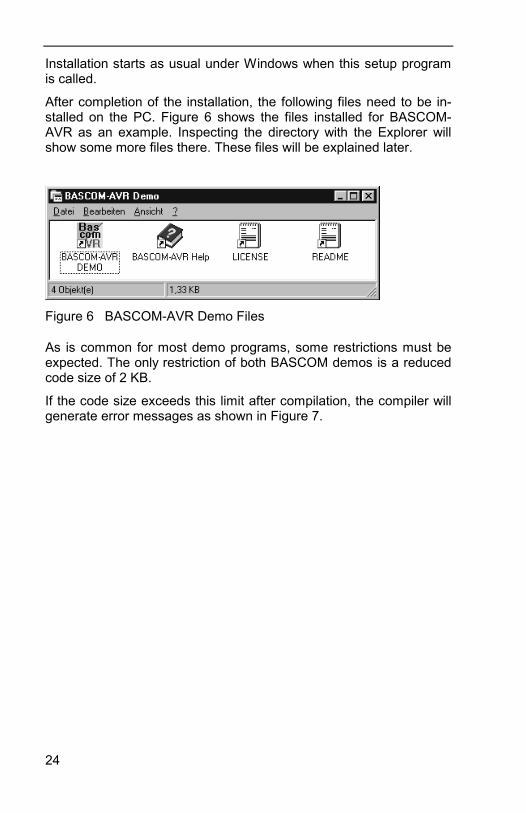
After completion of the installation, the following files need to be in-stalled on the PC. Figure 6 shows the files installed for BASCOM-AVR as an example. Inspecting the directory with the Explorer willshow some more files there. These files will be explained later.
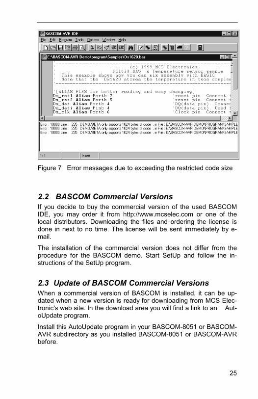
As is common for most demo programs, some restrictions must beexpected. The only restriction of both BASCOM demos is a reducedcode size of 2 KB.
If the code size exceeds this limit after compilation, the compiler willgenerate error messages as shown in Figure 7.
Figure 6 BASCOM-AVR Demo Files
25
2.2 BASCOM Commercial VersionsIf you decide to buy the commercial version of the used BASCOMIDE, you may order it from http://www.mcselec.com or one of thelocal distributors. Downloading the files and ordering the license isdone in next to no time. The license will be sent immediately by e-mail.
The installation of the commercial version does not differ from theprocedure for the BASCOM demo. Start SetUp and follow the in-structions of the SetUp program.
2.3 Update of BASCOM Commercial VersionsWhen a commercial version of BASCOM is installed, it can be up-dated when a new version is ready for downloading from MCS Elec-tronic's web site. In the download area you will find a link to an Aut-oUpdate program.
Install this AutoUpdate program in your BASCOM-8051 or BASCOM-AVR subdirectory as you installed BASCOM-8051 or BASCOM-AVRbefore.
Figure 7 Error messages due to exceeding the restricted code size


![Bascom AVR Programming [Basic]](https://img.pdfslide.net/doc/110x75/544a8b55b1af9f0f568b4d6d/bascom-avr-programming-basic.jpg)