Embed Size (px)
Citation preview
KIT# 3151-1A02/02/12
KSR
O
A
D
M
A
S
T
E
R,
I
N
C.
ROADMASTER, Inc. 6110 NE 127th Ave. Vancouver, WA 98682 360-896-0407 fax 360-735-9300 www.roadmasterinc.com
BASEPLATE KIT INSTALLATION INSTRUCTIONS
1
2 3
4
5
6
7
8
9 10
11
12
13
14
15
16
17
18
19
20
28 12 "± 1
2 "
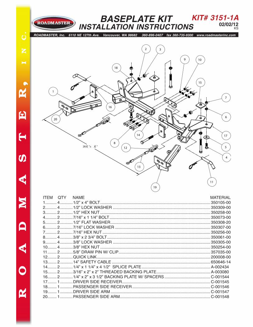
ITEM QTY NAME MATERIAL1.......... 4 ...........1/2” x 4” BOLT ................................................................................................ 350105-002.......... 4 ...........1/2” LOCK WASHER ..................................................................................... 350309-003.......... 2 ...........1/2” HEX NUT ................................................................................................ 350258-004.......... 2 ...........7/16” x 1 1/4” BOLT ........................................................................................ 350073-005.......... 2 ...........1/2” FLAT WASHER ....................................................................................... 350308-206.......... 2 ...........7/16” LOCK WASHER ................................................................................... 350307-007.......... 2 ...........7/16” HEX NUT .............................................................................................. 350256-008.......... 4 ...........3/8” x 2 3/4” BOLT .......................................................................................... 350061-009.......... 4 ...........3/8” LOCK WASHER ..................................................................................... 350305-0010........ 4 ...........3/8” HEX NUT ................................................................................................ 350254-0011 ........ 2 ...........5/8” DRAW PIN W/ CLIP ................................................................................ 357035-0012........ 2 ...........QUICK LINK ................................................................................................... 200008-0013........ 2 ...........14” SAFETY CABLE ...................................................................................... 650646-1414........ 2 ...........1/4” x 1 1/4” x 4 1/2” SPLICE PLATE ............................................................ A-00243415........ 2 ...........3/16” x 2” x 2” THREADED BACKING PLATE ............................................... A-00308016........ 2 ...........1/4” x 2” x 3 1/2” BACKING PLATE W/ SPACERS ........................................ C-00154417........ 1 ...........DRIVER SIDE RECEIVER ............................................................................. C-00154518........ 1 ...........PASSENGER SIDE RECEIVER .................................................................... C-00154619........ 1 ...........DRIVER SIDE ARM ....................................................................................... C-00154720........ 1 ...........PASSENGER SIDE ARM............................................................................... C-001548
KIT# 3151-1A02/02/12
KS
BASEPLATE KIT INSTALLATION INSTRUCTIONS
ROADMASTER, Inc. 6110 NE 127th Ave. Vancouver, WA 98682 360-896-0407 fax 360-735-9300 www.roadmasterinc.com
Fig.A
Fig.B
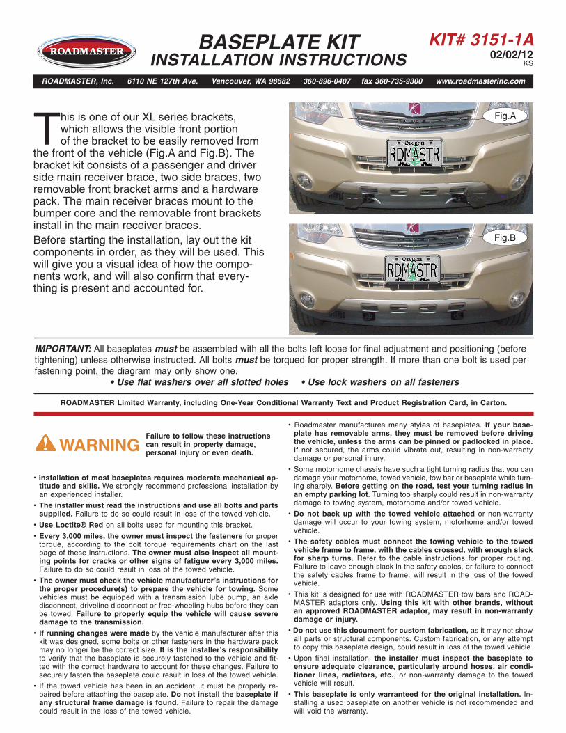
This is one of our XL series brackets, which allows the visible front portion of the bracket to be easily removed from
the front of the vehicle (Fig.A and Fig.B). The bracket kit consists of a passenger and driver side main receiver brace, two side braces, two removable front bracket arms and a hardware pack. The main receiver braces mount to the bumper core and the removable front brackets install in the main receiver braces.Before starting the installation, lay out the kit components in order, as they will be used. This will give you a visual idea of how the compo-nents work, and will also confirm that every-thing is present and accounted for.
IMPORTANT: All baseplates must be assembled with all the bolts left loose for final adjustment and positioning (before tightening) unless otherwise instructed. All bolts must be torqued for proper strength. If more than one bolt is used per fastening point, the diagram may only show one.
• Use flat washers over all slotted holes • Use lock washers on all fasteners
• Installation of most baseplates requires moderate mechanical ap-titude and skills. We strongly recommend professional installation byan experienced installer.
• The installer must read the instructions and use all bolts and partssupplied. Failure to do so could result in loss of the towed vehicle.
• Use Loctite® Red on all bolts used for mounting this bracket.
• Every 3,000 miles, the owner must inspect the fasteners for propertorque, according to the bolt torque requirements chart on the lastpage of these instructions. The owner must also inspect all mount-ing points for cracks or other signs of fatigue every 3,000 miles.Failure to do so could result in loss of the towed vehicle.
• The owner must check the vehicle manufacturer's instructions forthe proper procedure(s) to prepare the vehicle for towing. Somevehicles must be equipped with a transmission lube pump, an axledisconnect, driveline disconnect or free-wheeling hubs before they canbe towed. Failure to properly equip the vehicle will cause severedamage to the transmission.
• If running changes were made by the vehicle manufacturer after thiskit was designed, some bolts or other fasteners in the hardware packmay no longer be the correct size. It is the installer’s responsibilityto verify that the baseplate is securely fastened to the vehicle and fit-ted with the correct hardware to account for these changes. Failure tosecurely fasten the baseplate could result in loss of the towed vehicle.
• If the towed vehicle has been in an accident, it must be properly re-paired before attaching the baseplate. Do not install the baseplate ifany structural frame damage is found. Failure to repair the damagecould result in the loss of the towed vehicle.
ROADMASTER Limited Warranty, including One-Year Conditional Warranty Text and Product Registration Card, in Carton.
• Roadmaster manufactures many styles of baseplates. If your base-plate has removable arms, they must be removed before drivingthe vehicle, unless the arms can be pinned or padlocked in place.If not secured, the arms could vibrate out, resulting in non-warrantydamage or personal injury.
• Some motorhome chassis have such a tight turning radius that you candamage your motorhome, towed vehicle, tow bar or baseplate while turn-ing sharply. Before getting on the road, test your turning radius inan empty parking lot. Turning too sharply could result in non-warrantydamage to towing system, motorhome and/or towed vehicle.
• Do not back up with the towed vehicle attached or non-warrantydamage will occur to your towing system, motorhome and/or towedvehicle.
• The safety cables must connect the towing vehicle to the towedvehicle frame to frame, with the cables crossed, with enough slackfor sharp turns. Refer to the cable instructions for proper routing.Failure to leave enough slack in the safety cables, or failure to connectthe safety cables frame to frame, will result in the loss of the towedvehicle.
• This kit is designed for use with ROADMASTER tow bars and ROAD-MASTER adaptors only. Using this kit with other brands, withoutan approved ROADMASTER adaptor, may result in non-warrantydamage or injury.
• Do not use this document for custom fabrication, as it may not showall parts or structural components. Custom fabrication, or any attemptto copy this baseplate design, could result in loss of the towed vehicle.
• Upon final installation, the installer must inspect the baseplate toensure adequate clearance, particularly around hoses, air condi-tioner lines, radiators, etc., or non-warranty damage to the towedvehicle will result.
• This baseplate is only warranteed for the original installation. In-stalling a used baseplate on another vehicle is not recommended andwill void the warranty.
Failure to follow these instructions can result in property damage, personal injury or even death.WARNING
KIT# 3151-1A02/02/12
KS
Fig.C Fig.D Fig.E
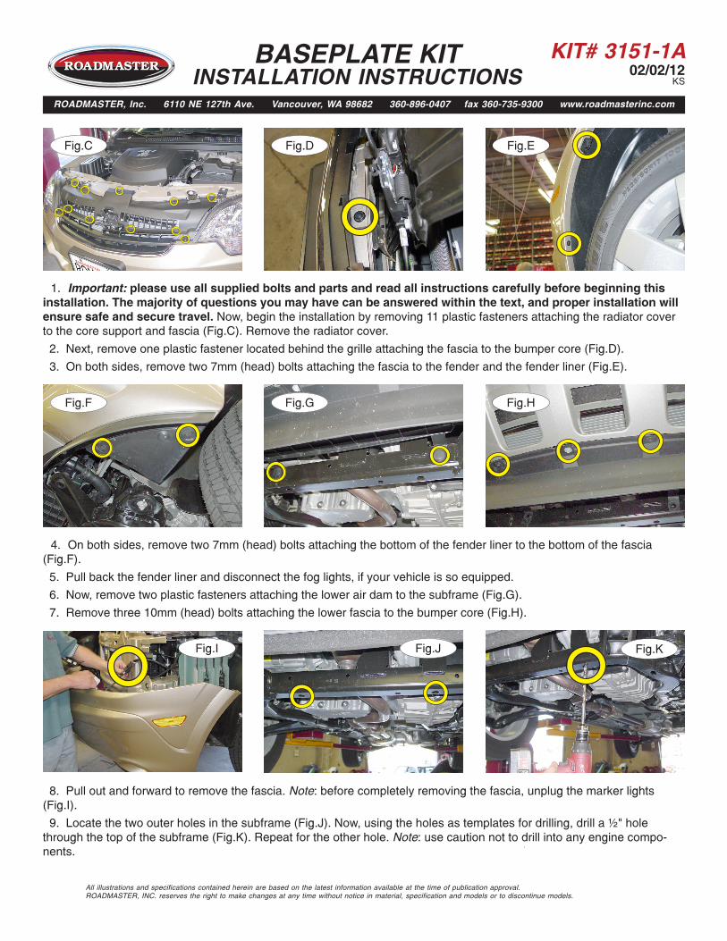
1. Important: please use all supplied bolts and parts and read all instructions carefully before beginning this installation. The majority of questions you may have can be answered within the text, and proper installation will ensure safe and secure travel. Now, begin the installation by removing 11 plastic fasteners attaching the radiator cover to the core support and fascia (Fig.C). Remove the radiator cover.
2. Next, remove one plastic fastener located behind the grille attaching the fascia to the bumper core (Fig.D).
3. On both sides, remove two 7mm (head) bolts attaching the fascia to the fender and the fender liner (Fig.E).
Fig.G Fig.HFig.F
4. On both sides, remove two 7mm (head) bolts attaching the bottom of the fender liner to the bottom of the fascia (Fig.F).
5. Pull back the fender liner and disconnect the fog lights, if your vehicle is so equipped.
6. Now, remove two plastic fasteners attaching the lower air dam to the subframe (Fig.G).
7. Remove three 10mm (head) bolts attaching the lower fascia to the bumper core (Fig.H).
Fig.I Fig.J
8. Pull out and forward to remove the fascia. Note: before completely removing the fascia, unplug the marker lights (Fig.I).
9. Locate the two outer holes in the subframe (Fig.J). Now, using the holes as templates for drilling, drill a ½" hole through the top of the subframe (Fig.K). Repeat for the other hole. Note: use caution not to drill into any engine compo-nents.
Fig.K
BASEPLATE KIT INSTALLATION INSTRUCTIONS
ROADMASTER, Inc. 6110 NE 127th Ave. Vancouver, WA 98682 360-896-0407 fax 360-735-9300 www.roadmasterinc.com
All illustrations and specifications contained herein are based on the latest information available at the time of publication approval. ROADMASTER, INC. reserves the right to make changes at any time without notice in material, specification and models or to discontinue models.
KIT# 3151-1A02/02/12
KS
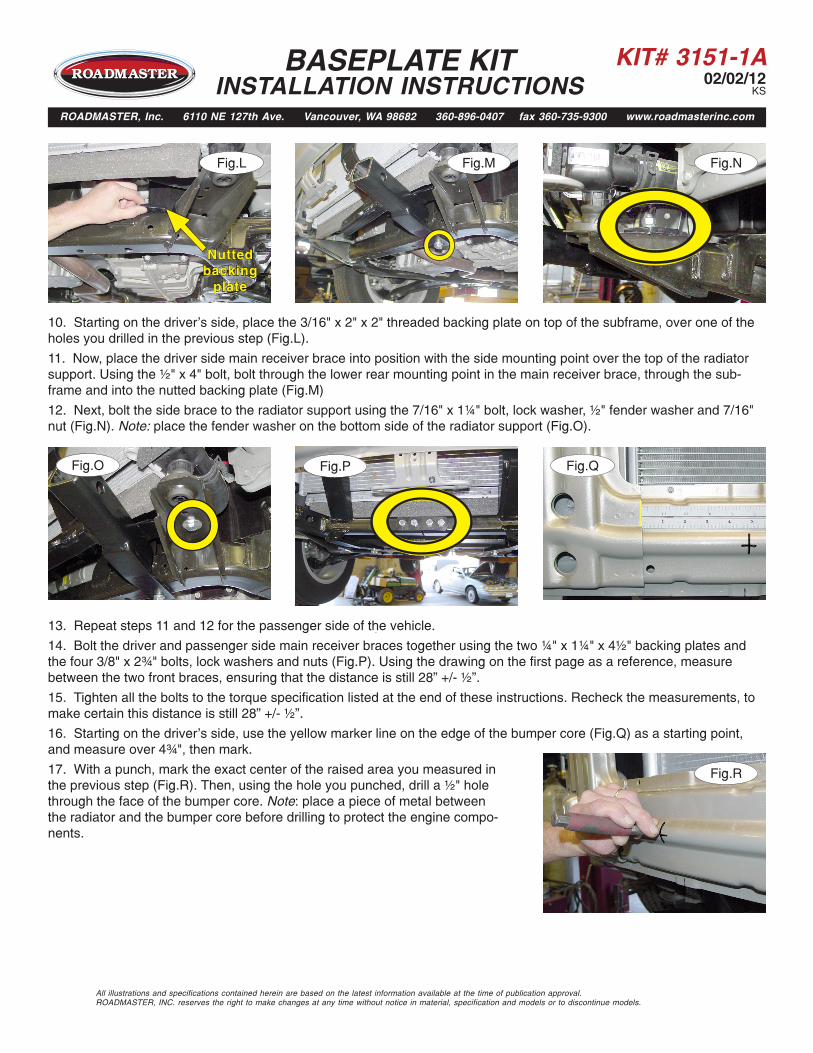
13. Repeat steps 11 and 12 for the passenger side of the vehicle.
14. Bolt the driver and passenger side main receiver braces together using the two ¼" x 1¼" x 4½" backing plates and the four 3/8" x 2¾" bolts, lock washers and nuts (Fig.P). Using the drawing on the first page as a reference, measure between the two front braces, ensuring that the distance is still 28” +/- ½”.
15. Tighten all the bolts to the torque specification listed at the end of these instructions. Recheck the measurements, to make certain this distance is still 28” +/- ½”.
16. Starting on the driver's side, use the yellow marker line on the edge of the bumper core (Fig.Q) as a starting point, and measure over 4¾", then mark.
17. With a punch, mark the exact center of the raised area you measured in the previous step (Fig.R). Then, using the hole you punched, drill a ½" hole through the face of the bumper core. Note: place a piece of metal between the radiator and the bumper core before drilling to protect the engine compo-nents.
Fig.MFig.L Fig.N
10. Starting on the driver's side, place the 3/16" x 2" x 2" threaded backing plate on top of the subframe, over one of the holes you drilled in the previous step (Fig.L).
11. Now, place the driver side main receiver brace into position with the side mounting point over the top of the radiator support. Using the ½" x 4" bolt, bolt through the lower rear mounting point in the main receiver brace, through the sub-frame and into the nutted backing plate (Fig.M)
12. Next, bolt the side brace to the radiator support using the 7/16" x 1¼" bolt, lock washer, ½" fender washer and 7/16" nut (Fig.N). Note: place the fender washer on the bottom side of the radiator support (Fig.O).
Fig.PFig.O Fig.Q
Fig.R
All illustrations and specifications contained herein are based on the latest information available at the time of publication approval. ROADMASTER, INC. reserves the right to make changes at any time without notice in material, specification and models or to discontinue models.
BASEPLATE KIT INSTALLATION INSTRUCTIONS
ROADMASTER, Inc. 6110 NE 127th Ave. Vancouver, WA 98682 360-896-0407 fax 360-735-9300 www.roadmasterinc.com
Nutted backing
plate
KIT# 3151-1A02/02/12
KS
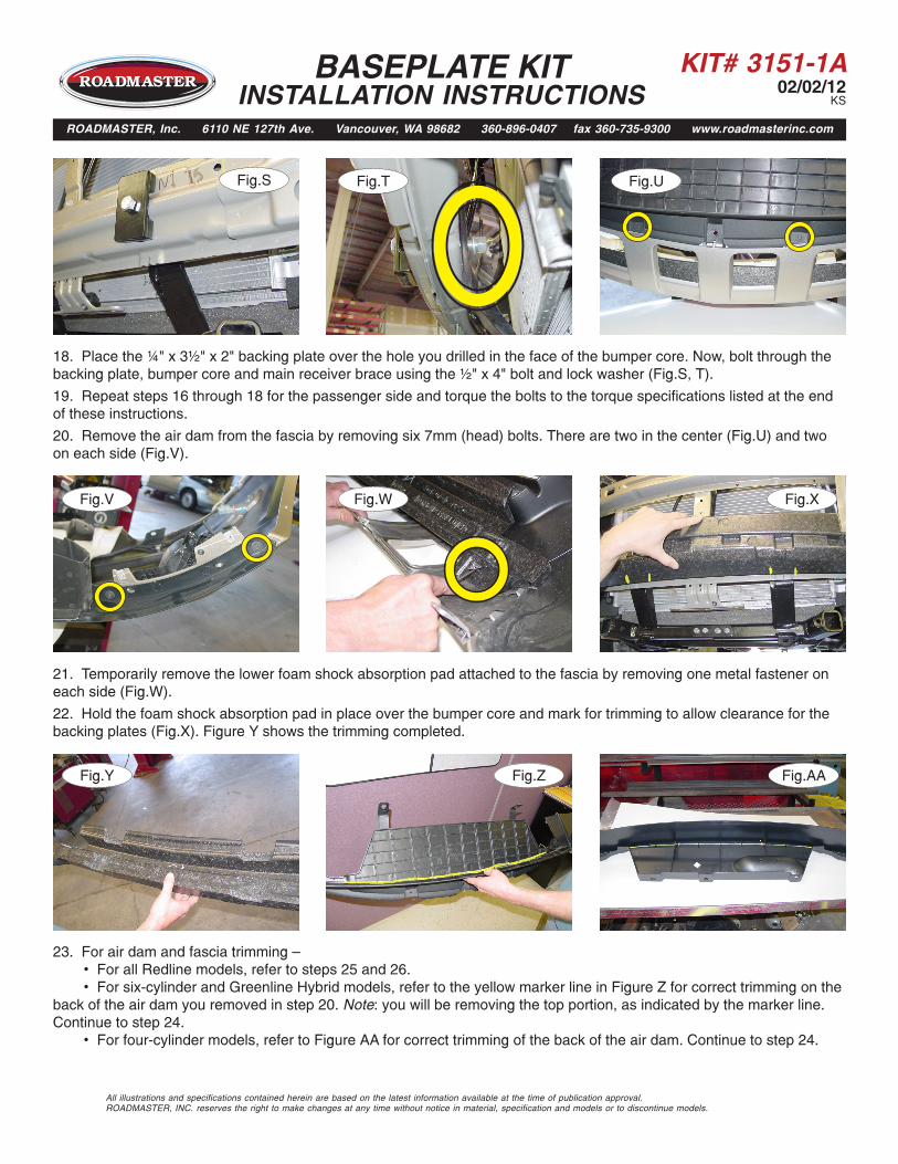
18. Place the ¼" x 3½" x 2" backing plate over the hole you drilled in the face of the bumper core. Now, bolt through the backing plate, bumper core and main receiver brace using the ½" x 4" bolt and lock washer (Fig.S, T).
19. Repeat steps 16 through 18 for the passenger side and torque the bolts to the torque specifications listed at the end of these instructions.
20. Remove the air dam from the fascia by removing six 7mm (head) bolts. There are two in the center (Fig.U) and two on each side (Fig.V).
Fig.TFig.S Fig.U
Fig.V Fig.W
21. Temporarily remove the lower foam shock absorption pad attached to the fascia by removing one metal fastener on each side (Fig.W).
22. Hold the foam shock absorption pad in place over the bumper core and mark for trimming to allow clearance for the backing plates (Fig.X). Figure Y shows the trimming completed.
Fig.X
Fig.Y Fig.Z Fig.AA
23. For air dam and fascia trimming — • For all Redline models, refer to steps 25 and 26. • For six-cylinder and Greenline Hybrid models, refer to the yellow marker line in Figure Z for correct trimming on the back of the air dam you removed in step 20. Note: you will be removing the top portion, as indicated by the marker line. Continue to step 24. • For four-cylinder models, refer to Figure AA for correct trimming of the back of the air dam. Continue to step 24.
All illustrations and specifications contained herein are based on the latest information available at the time of publication approval. ROADMASTER, INC. reserves the right to make changes at any time without notice in material, specification and models or to discontinue models.
BASEPLATE KIT INSTALLATION INSTRUCTIONS
ROADMASTER, Inc. 6110 NE 127th Ave. Vancouver, WA 98682 360-896-0407 fax 360-735-9300 www.roadmasterinc.com
KIT# 3151-1A02/02/12
KS
Fig.FF
All illustrations and specifications contained herein are based on the latest information available at the time of publication approval. ROADMASTER, INC. reserves the right to make changes at any time without notice in material, specification and models or to discontinue models.
Fig.EE
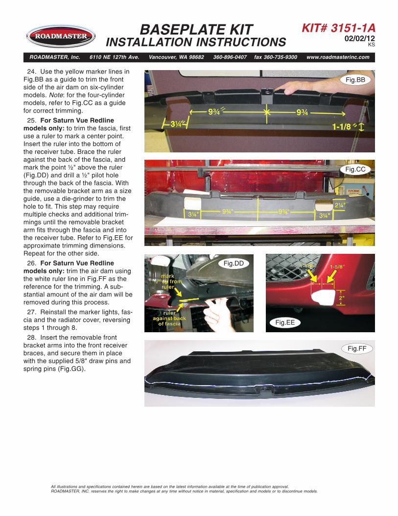
24. Use the yellow marker lines in Fig.BB as a guide to trim the front side of the air dam on six-cylinder models. Note: for the four-cylinder models, refer to Fig.CC as a guide for correct trimming.
25. For Saturn Vue Redline models only: to trim the fascia, first use a ruler to mark a center point. Insert the ruler into the bottom of the receiver tube. Brace the ruler against the back of the fascia, and mark the point ½" above the ruler (Fig.DD) and drill a ½" pilot hole through the back of the fascia. With the removable bracket arm as a size guide, use a die-grinder to trim the hole to fit. This step may require multiple checks and additional trim-mings until the removable bracket arm fits through the fascia and into the receiver tube. Refer to Fig.EE for approximate trimming dimensions. Repeat for the other side.
26. For Saturn Vue Redline models only: trim the air dam using the white ruler line in Fig.FF as the reference for the trimming. A sub-stantial amount of the air dam will be removed during this process.
27. Reinstall the marker lights, fas-cia and the radiator cover, reversing steps 1 through 8.
28. Insert the removable front bracket arms into the front receiver braces, and secure them in place with the supplied 5/8" draw pins and spring pins (Fig.GG).
BASEPLATE KIT INSTALLATION INSTRUCTIONS
ROADMASTER, Inc. 6110 NE 127th Ave. Vancouver, WA 98682 360-896-0407 fax 360-735-9300 www.roadmasterinc.com
Fig.ZFig.BB
Fig.DD
Fig.CC
KIT# 3151-1A02/02/12
KS
All illustrations and specifications contained herein are based on the latest information available at the time of publication approval. ROADMASTER, INC. reserves the right to make changes at any time without notice in material, specification and models or to discontinue models.
BOLT TORQUE REQUIREMENTS
METRIC BOLTSThread Size Grade Plated / Unplated12mm-1.25 ........8.8 ............70 ft./lb. 65 ft./lb. 12mm-1.5 ..........8.8 ............66 ft./lb. 61 ft./lb.12mm-1.75 ........8.8 ...........65 ft./lb. 60 ft./lb.14mm-2.0 ..........8.8 .........104 ft./lb. 97 ft./lb.
METRIC BOLTSThread Size Grade Plated / Unplated 8mm-1.0 ............8.8 ............20 ft./lb. 18 ft./lb. 8mm-1.25 .........8.8 ............19 ft./lb. 18 ft./lb.10mm-1.25 ........8.8 ...........38 ft./lb. 36 ft./lb.10mm-1.5 ..........8.8 ...........37 ft./lb. 35 ft./lb.
STANDARD BOLTSThread Size Grade Torque5/16..................... 5 ........................... 13 ft./lb. 3/8....................... 5 ........................... 23 ft./lb.7/16..................... 5 ........................... 37 ft./lb.1/2....................... 5 ........................... 56 ft./lb.5/8....................... 5 ......................... 150 ft./lb.
Note: The torque values represented below are intended as general guidelines. Torque requirements for specific applications may vary. Roadmaster does not warrant this information to be accurate for all applications and disclaims all liability for any claims or damages which may result from its use.
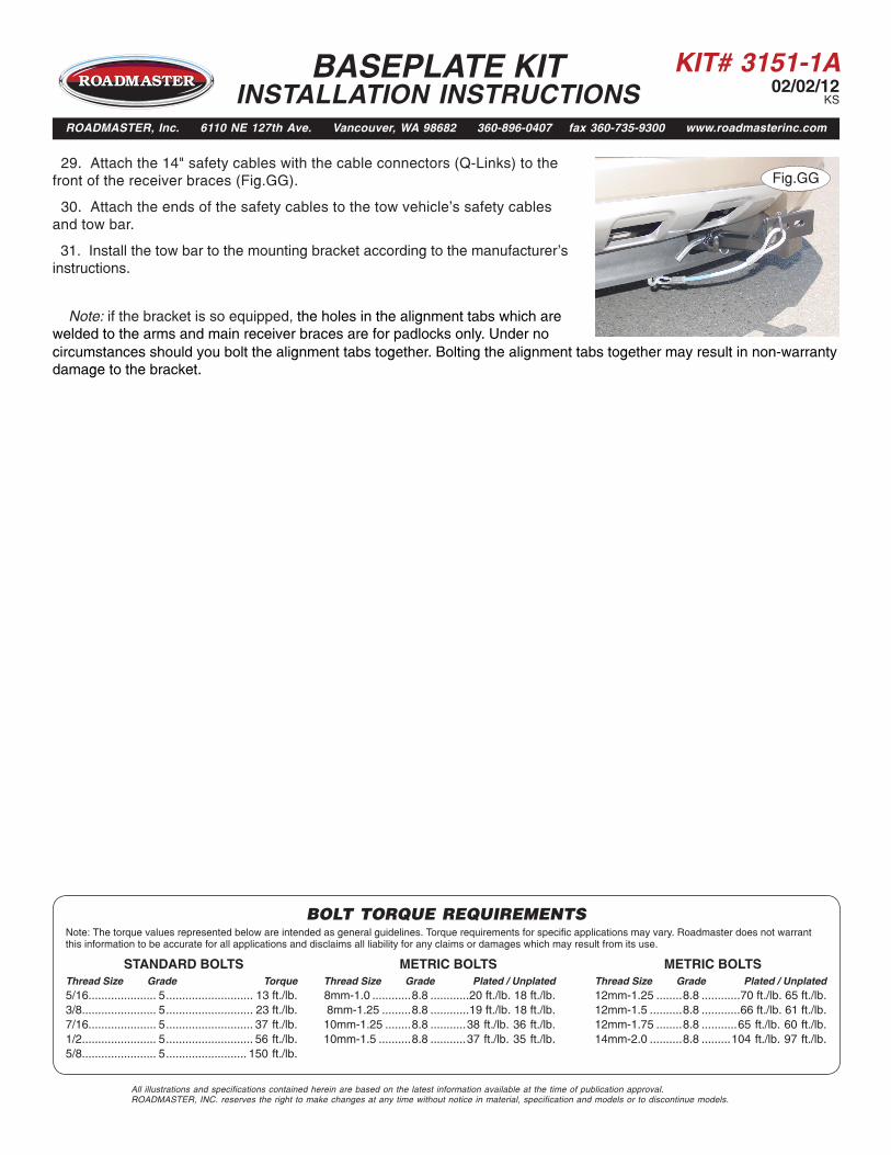
Fig.GG 29. Attach the 14" safety cables with the cable connectors (Q-Links) to the front of the receiver braces (Fig.GG).
30. Attach the ends of the safety cables to the tow vehicle's safety cables and tow bar.
31. Install the tow bar to the mounting bracket according to the manufacturer's instructions.
Note: if the bracket is so equipped, the holes in the alignment tabs which are welded to the arms and main receiver braces are for padlocks only. Under no
BASEPLATE KIT INSTALLATION INSTRUCTIONS
ROADMASTER, Inc. 6110 NE 127th Ave. Vancouver, WA 98682 360-896-0407 fax 360-735-9300 www.roadmasterinc.com
circumstances should you bolt the alignment tabs together. Bolting the alignment tabs together may result in non-warranty damage to the bracket.