Embed Size (px)
Citation preview
Basic Cyclone Design
Bill Heumann
Introduction
• Brief history• What is a cyclone?
– A device that separates particulate from gas (fluid) by centrifugal force
– Works simply by the kinetic energy of the incoming mixture (flow stream) and the geometry of the cyclone

How Cyclones Work:
Nomenclature
Outlet Pipe/Vortex Finder
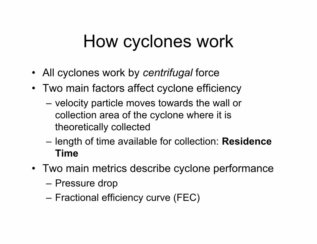
How cyclones work• All cyclones work by centrifugal force• Two main factors affect cyclone efficiency
– velocity particle moves towards the wall or collection area of the cyclone where it is theoretically collected
– length of time available for collection: Residence Time
• Two main metrics describe cyclone performance– Pressure drop– Fractional efficiency curve (FEC)
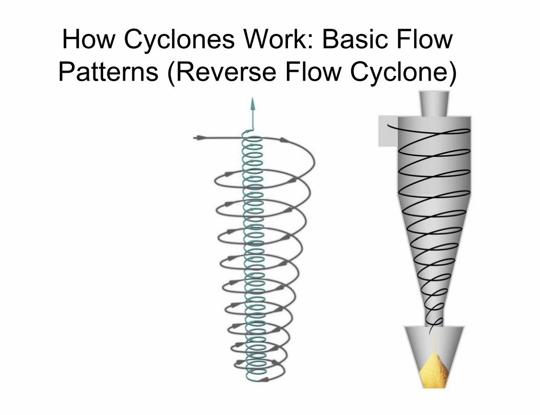
How Cyclones Work: Basic Flow Patterns (Reverse Flow Cyclone)

Another Kind of Cyclone

How Cyclones Work: Basic Flow/Pressure Patterns
Tangential Velocity
Axial Velocity
Static Pressure
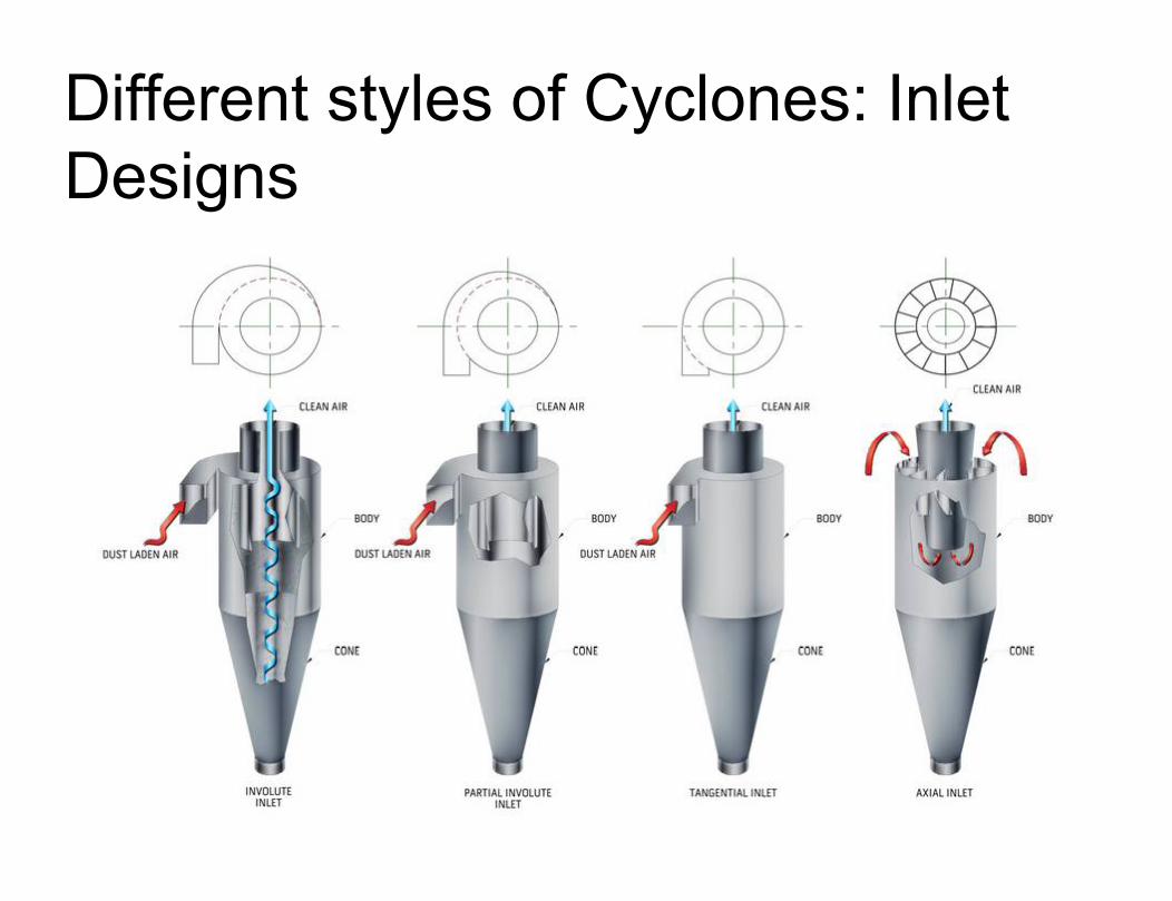
Different styles of Cyclones: Inlet Designs
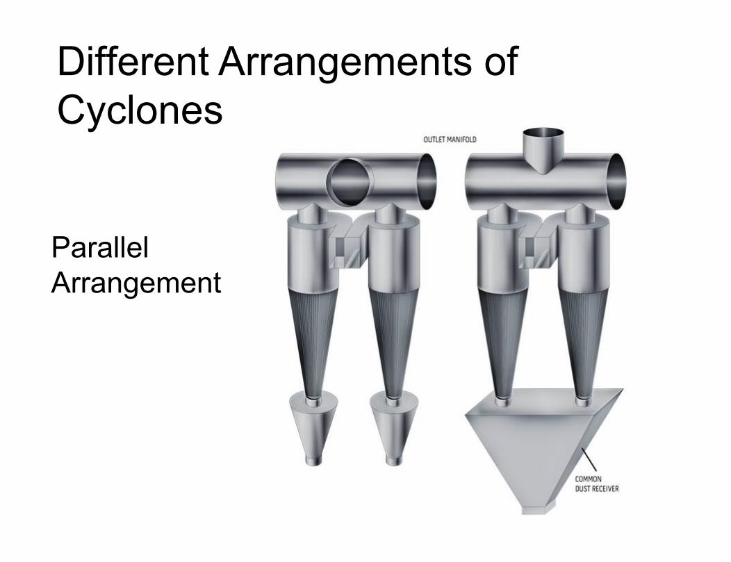
Different Arrangements of Cyclones
Parallel Arrangement

Different Arrangements of Cyclones: Series
Arrangement
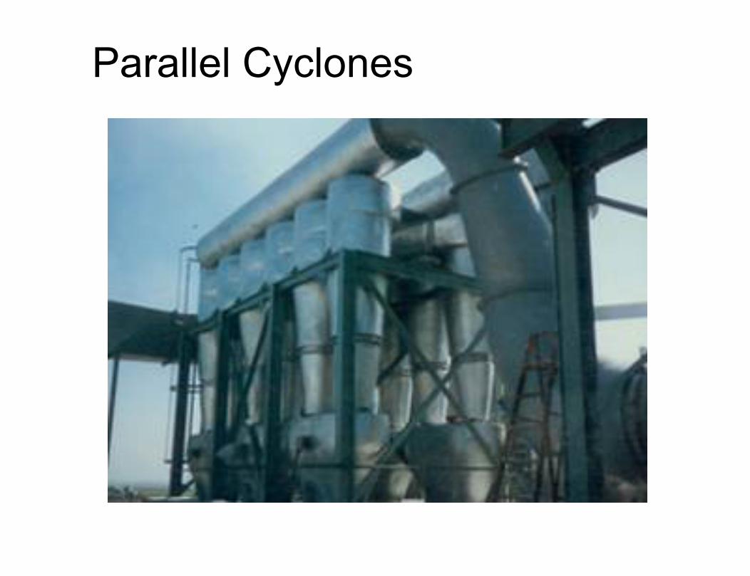
Parallel Cyclones
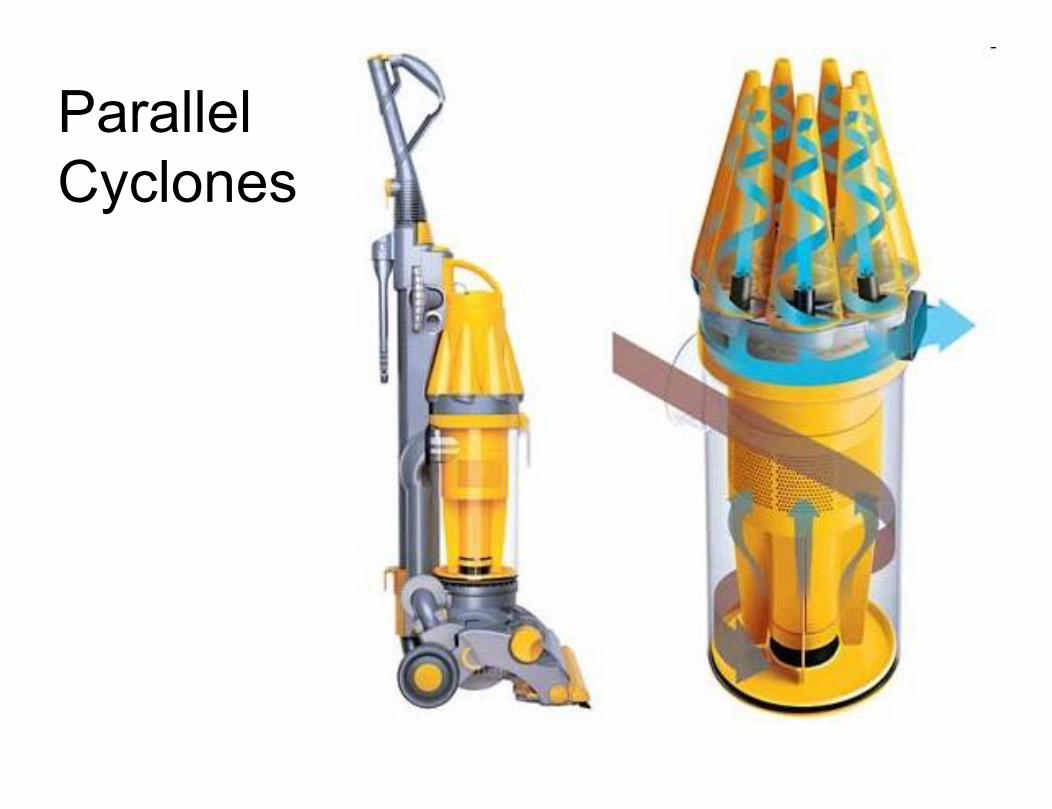
Parallel Cyclones
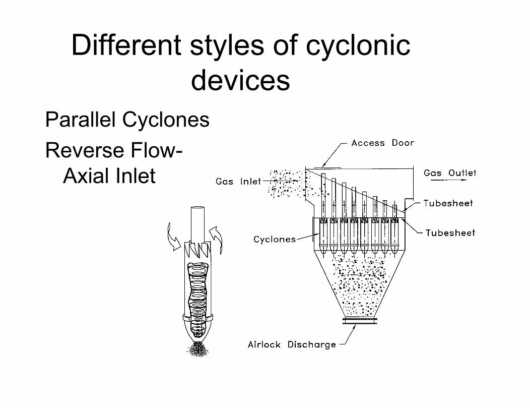
Different styles of cyclonic devices
Parallel CyclonesReverse Flow-
Axial Inlet
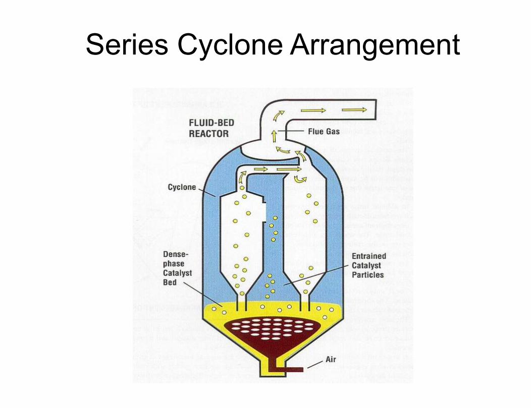
Series Cyclone Arrangement
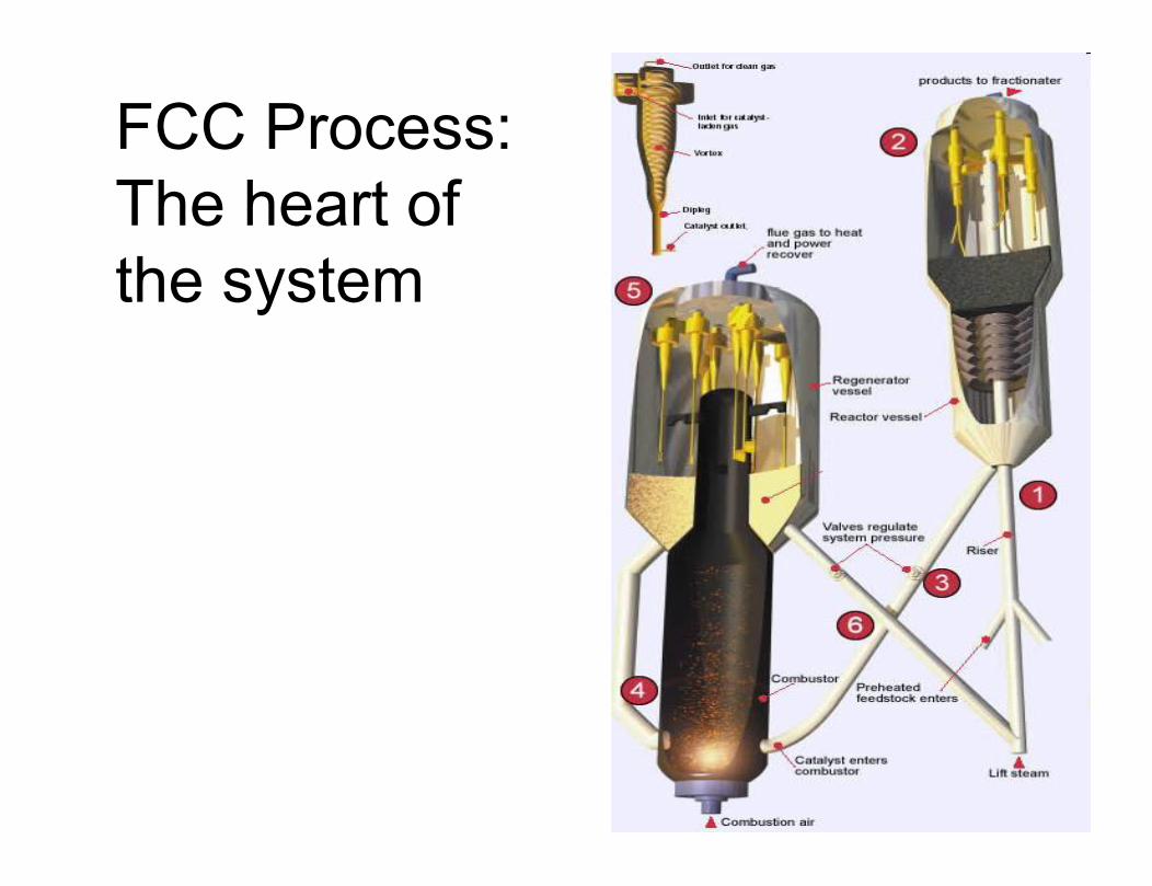
FCC Process: The heart of the system
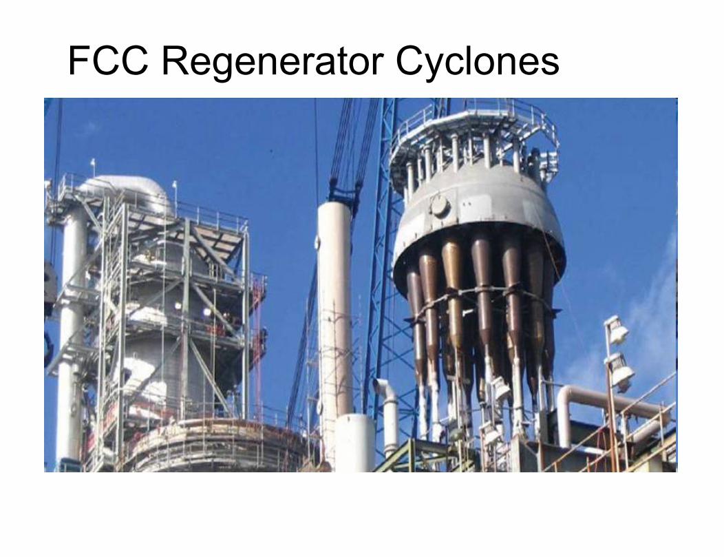
FCC Regenerator Cyclones
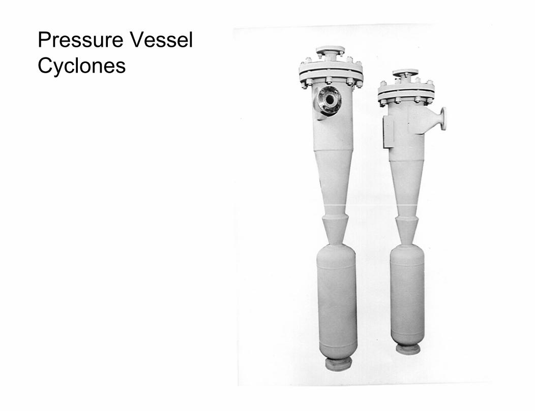
Pressure Vessel Cyclones
A cyclone picture of another sort..
Why Use Cyclones?
• Dry• No moving parts• Robust Construction• Can be easily designed for very severe
duty (examples)• Low cost (sometimes)• Safety
When do you use a cyclone?
• When it is the most economical solution!– Capital Costs– Installation Costs– Operating Expenses– Maintenance Expense– Depreciation (life expectancy)– Safety and liability issue– Product recovery– System operability– Effects on downstream equipment and process
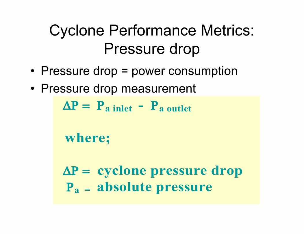
Cyclone Performance Metrics: Pressure drop
• Pressure drop = power consumption• Pressure drop measurement
a inlet - a outlet
where;
cyclone pressure dropa = absolute pressure
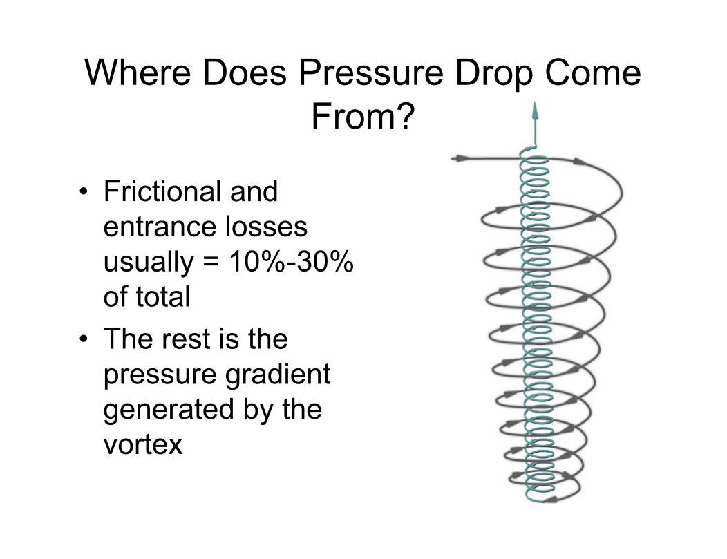
Where Does Pressure Drop Come From?
• Frictional and entrance losses usually = 10%-30% of total
• The rest is the pressure gradient generated by the vortex

Pressure drop @ no load• Basic pressure drop equation
( Q2/Q1)E(/1)
where;
Q = gas flow rateE = geometry exponent (1.9-2.3) = gas density
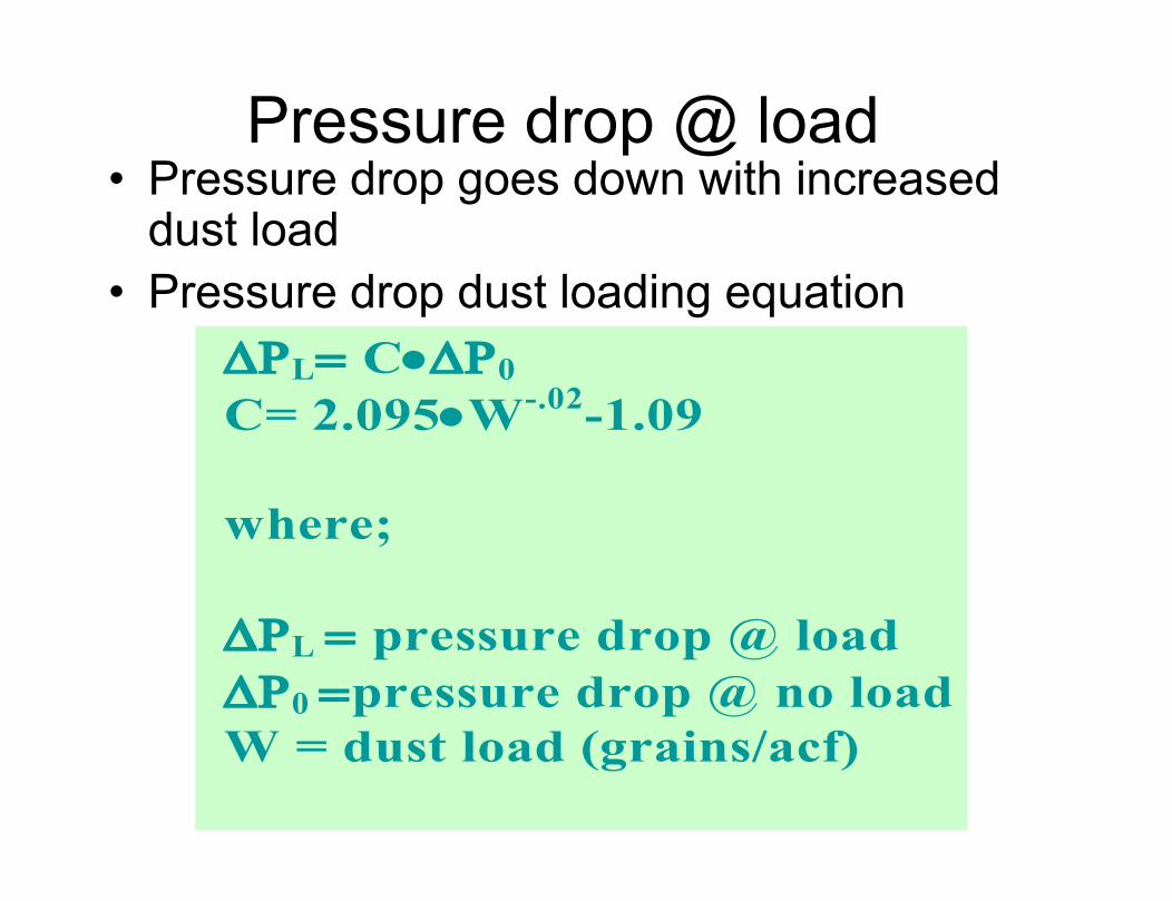
Pressure drop @ load• Pressure drop goes down with increased
dust load• Pressure drop dust loading equation
L C0C= 2.095W-.02-1.09
where;
L pressure drop @ load0 pressure drop @ no loadW = dust load (grains/acf)

Fractional efficiencies
• collection efficiency @ various particle sizes
• fractional or size efficiency curve• may be graphical or tabular

Example Size Efficiency Curve
Particle Diameter (microns)
% collection (B.W)
1 5
3 74
5 92
10 98.74
30 99.4
50 99.8
100 99.99
FEC Variables
• Cyclone Geometry• Cyclone Velocities• Particle Density• Gas Viscosity• Dust Load
Cyclone Total Collection Efficiency
• Function of the cyclone FEC and incoming Particle Size Distribution (PSD)
• Cyclone Total Collection Efficiency can vary greatly but it may be doing exactly the same thing!
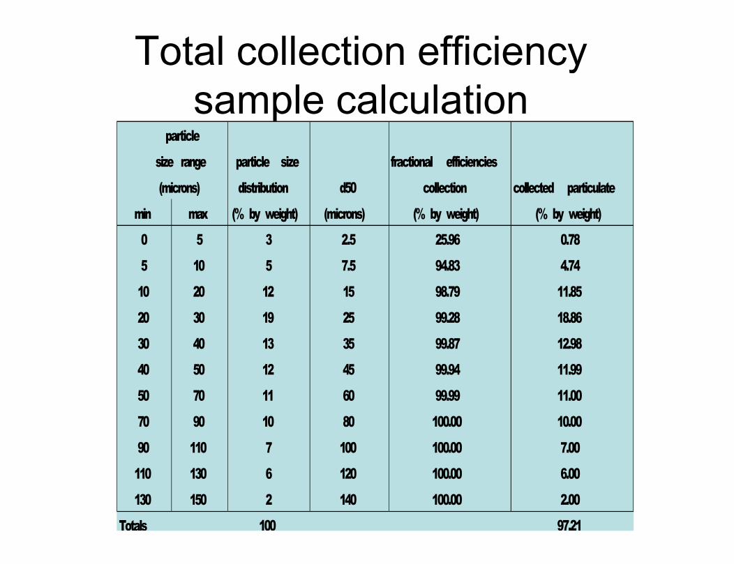
Total collection efficiency sample calculation
particle
size range particle size fractional efficiencies
(microns) distribution d50 collection collected particulate
min max (% by weight) (microns) (% by weight) (% by weight)
0 5 3 2.5 25.96 0.78
5 10 5 7.5 94.83 4.74
10 20 12 15 98.79 11.85
20 30 19 25 99.28 18.86
30 40 13 35 99.87 12.98
40 50 12 45 99.94 11.99
50 70 11 60 99.99 11.00
70 90 10 80 100.00 10.00
90 110 7 100 100.00 7.00
110 130 6 120 100.00 6.00
130 150 2 140 100.00 2.00
Totals 100 97.21

• Inlet configuration and ratio• Cyclone L/D Ratio• Outlet pipe penetration• Dust receiver • Residence time
Tools for Increased Cyclone Efficiency: Cyclone Geometry Variables

Tools for Increased Cyclone Efficiency: High Residence Time
High Capacity/Low Residence Time
High Residence Time/Low Capacity
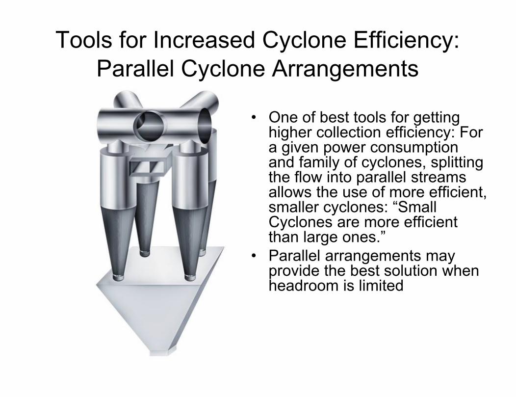
Tools for Increased Cyclone Efficiency:Parallel Cyclone Arrangements
• One of best tools for getting higher collection efficiency: For a given power consumption and family of cyclones, splitting the flow into parallel streams allows the use of more efficient, smaller cyclones: “Small Cyclones are more efficient than large ones.”
• Parallel arrangements may provide the best solution when headroom is limited
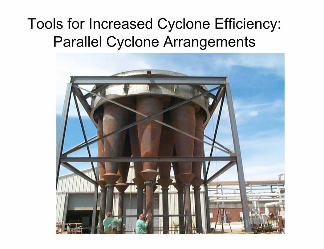
Tools for Increased Cyclone Efficiency:Parallel Cyclone Arrangements

Tools for Increased Cyclone Efficiency:Series Cyclone Arrangements
• Can provide higher collection efficiency for a limited inlet velocity because of the cumulative efficiency: 90% @ 5 micron + 90% @ 5 micron= 99% @ 5 micron
• May provide for redundancy in the event of system upsets
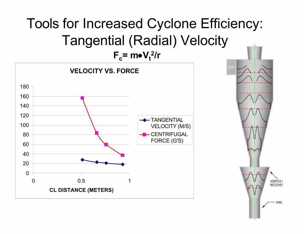
VELOCITY VS. FORCE
0
20
40
60
80
100
120
140
160
180
0 0.5 1
CL DISTANCE (METERS)
TANGENTIALVELOCITY (M/S)CENTRIFUGALFORCE (G'S)
Tools for Increased Cyclone Efficiency:Tangential (Radial) Velocity
Fc= mVt2/r
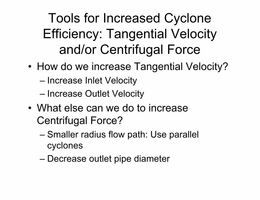
• How do we increase Tangential Velocity?– Increase Inlet Velocity– Increase Outlet Velocity
• What else can we do to increase Centrifugal Force?– Smaller radius flow path: Use parallel
cyclones– Decrease outlet pipe diameter
Tools for Increased Cyclone Efficiency: Tangential Velocity
and/or Centrifugal Force
Other Tools for Increased Efficiency: Geometry
• L/D Ratio • Inlet Design• Optimum Outlet Pipe Length• Dust Receivers

Other Tools for Increased Efficiency: Arrangement
• Cyclones in Parallel– Takes advantage of rule that says “for
cyclones of the same family (geometrically proportional) at the same operating conditions, smaller cyclones are more efficient than larger ones
• Cyclones in Series– Redundant chances for particle collection
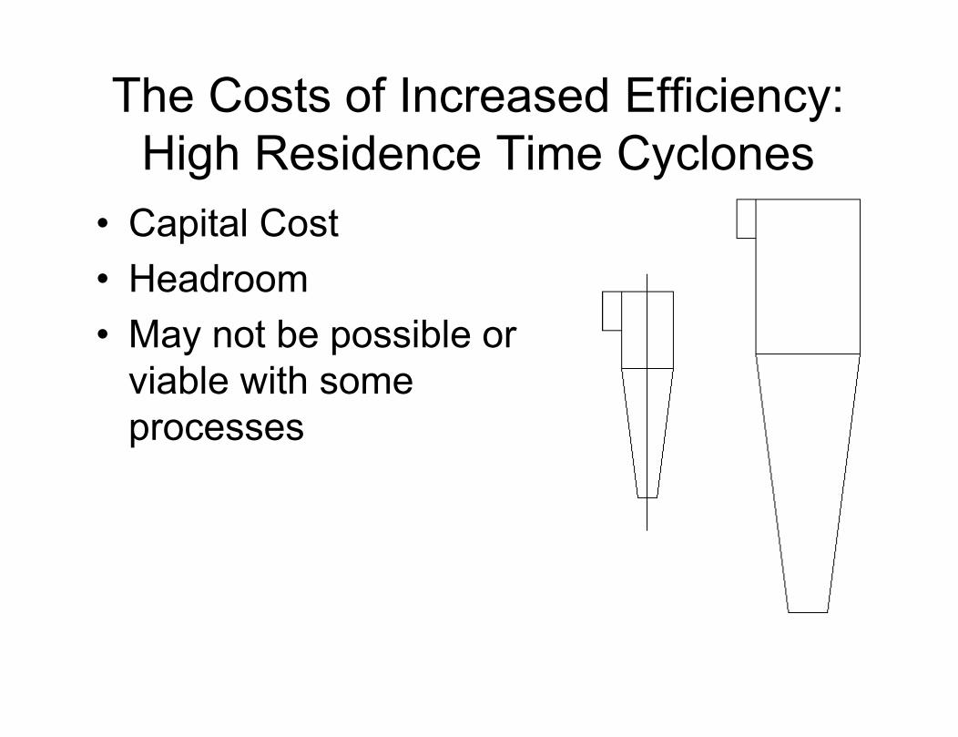
The Costs of Increased Efficiency: High Residence Time Cyclones
• Capital Cost• Headroom • May not be possible or
viable with some processes

• Capital Costs• Manifolding can be expensive and difficult• Pneumatic isolation can be difficult or cost
prohibitive• More horizontal space required
The Costs of Increased Efficiency: Parallel Cyclones

• Capital Costs• Manifolding can be expensive and difficult• More horizontal space required• Pressure Drop is Cumulative• Diminished benefit as PSD gets smaller
The Costs of Increased Efficiency: Series Cyclones
• Pressure Drop (Power Consumption)• Erosion• Particle Attrition• Re-entrainment• At very high velocities may have
acoustical and/or Ranque-Hilsch effects
The Costs of Increased Efficiency: Increased Velocity
How Cyclones Fail
• Improperly Designed– Incorrect or inaccurate design data– Lack of know how by cyclone designer- after all,
“anyone can build a cyclone”• Leakage into the cyclone• Plugged cyclones• Cyclones wear out too quickly
How Cyclones Fail: Design/ Fabrication Errors
• No dust receiver• Short outlet pipes• Dished heads• Poor or non existent airlocks• Instruments or access ports installed into
cyclonic flow streams• Related equipment not designed for cyclonic
flow• Inlet elbows, transitions, or other obstructions

• For More Information Visit www.heumannenviro.com
• Contact:Bill Heumann4898 Brownsboro Road, Suite 300Louisville, KY 40207PH: 502.742.9677Mobile: [email protected]