Embed Size (px)
Citation preview

Basic Electricity Principles & Boiler Wiring
Fundamentals
Presented by Steve Connor
April 20, 2016

2
Today’s Topics
Some basics & historical background
Electricity and its “current” types
The advantages and disadvantages
Terms and definitions you need to know
Basic Circuits and control devices; then
applied to a boiler wiring circuit
1
2
3
4• Importance of Training
• Summary and Q&A

First law of Thermodynamics
3
First Law:
• The energy of the universe is constant; it can be neither
created or destroyed, but only transferred and
transformed.
• The energy can be harnessed to produce work.
The Atom Elements
4
-Free Electron
+
+
-

Illuminating America 1878
5
Thomas Edison
Nikola Tesla

Direct Current Power
6
• Electric light bulb
• Phonograph
• Motion pictures
• Vote Recorder
• Iron ore separator
All DC powered

DC power Generator
7
DC Generator
Steam Boiler

Alternating Current Power
8

9
AC Generator
Steam Boiler

The Investor “Sharks” 1878/79
10
Edison
JP Morgan
Cornelius Vanderbilt

Edison electrifies Menlo Park
11

Edison electrifies the Columbia
12

Investment “Shark” 1884
13
Tesla
George Westinghouse

War of the Currents
14

Chicago Worlds Fair, 1893
15
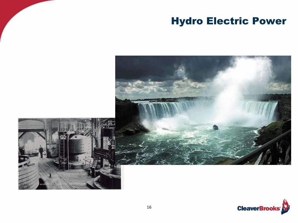
Hydro Electric Power
16
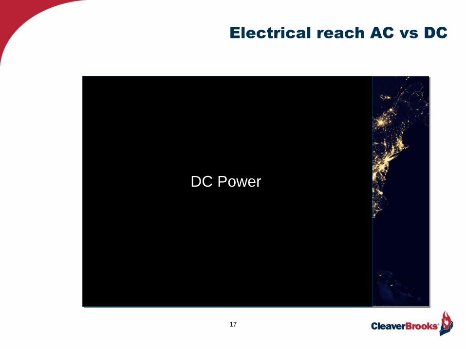
Electrical reach AC vs DC
17
DC Power

18
AC Power
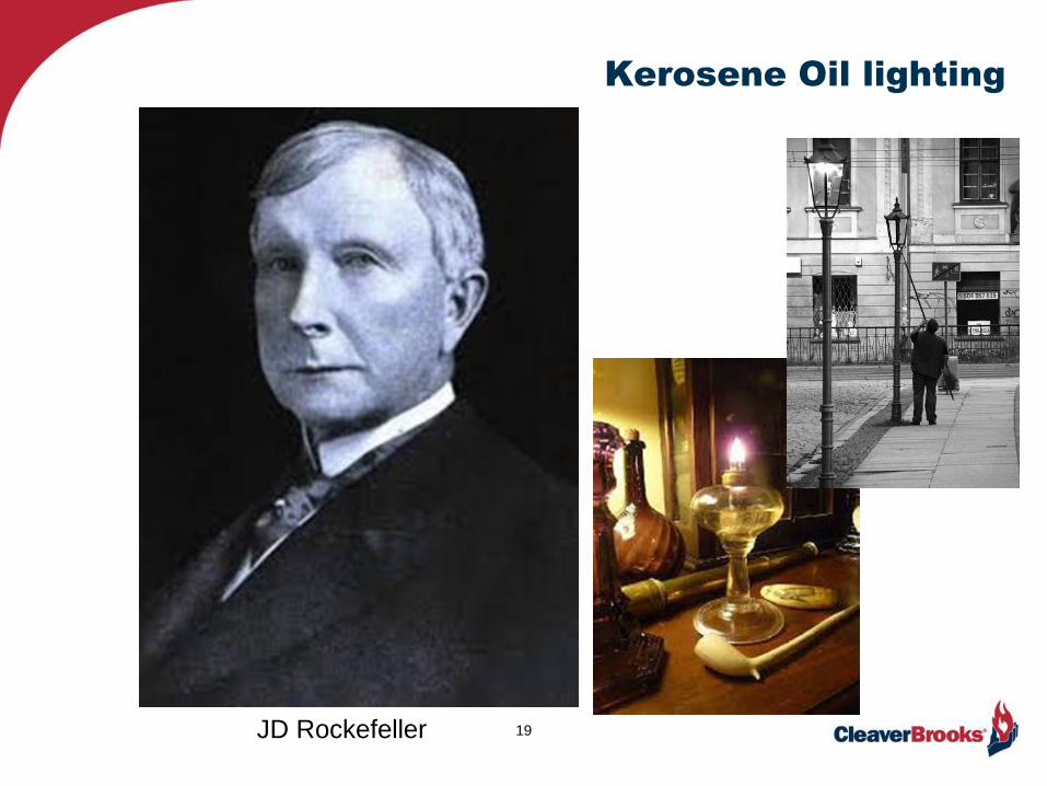
Kerosene Oil lighting
19JD Rockefeller

What is AC & DC Current?
20

Old steam turbine & Hydro power
21

DC Power Generator
22

Alternating Current
23
Sinusoidal Flow
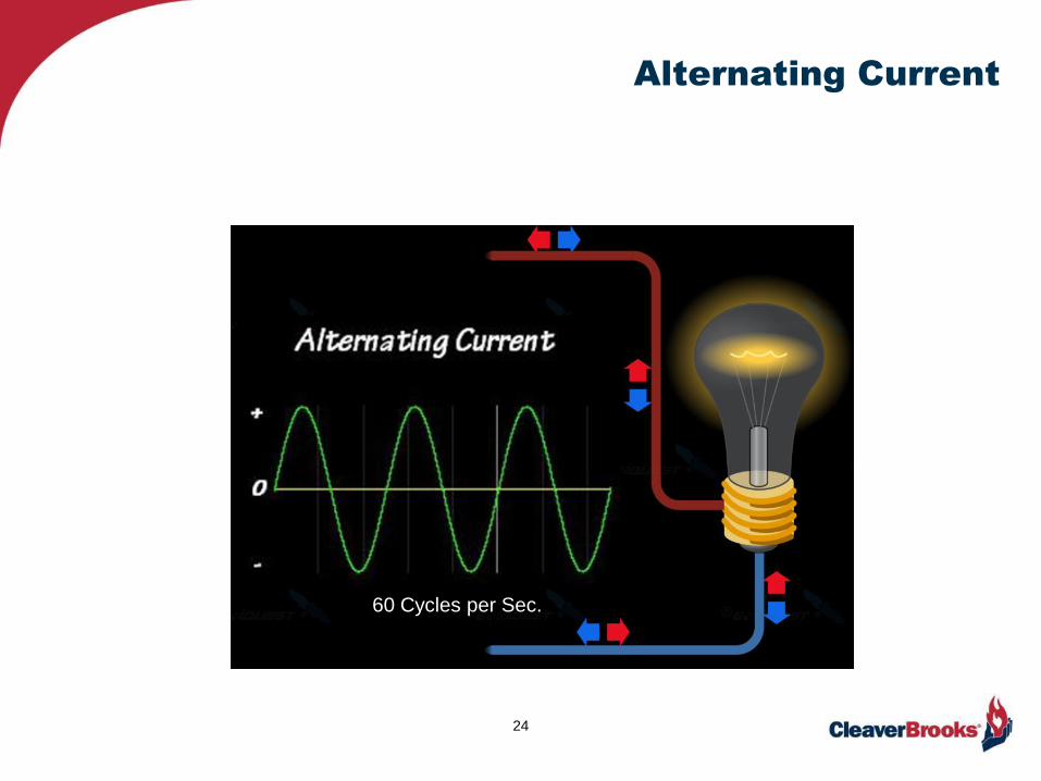
Alternating Current
24
60 Cycles per Sec.
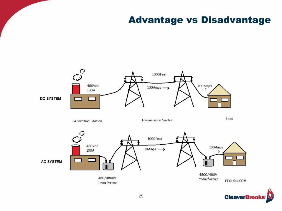
Advantage vs Disadvantage
25

Transforming AC Power
26
High Voltage Boosting TransformerPower Reducing Transformer
Line to house

Converting AC to DC
27

AC vs DC Voltage
28
DC AC

Terminology
29
• Ampere: The flow of an electrical charge through 1 ohm by force of 1 volt
• Current: Electrical flow measured in Amperes (Amps)
• Watt: The total power of a circuit at any given moment. [Volts X Amps = Watts]
• Kilowatt: One thousand Watts
• Hertz: Unit of frequency equaling one cycle per second (Hz)
• Voltage: Electrical potential difference between two points: Electromotive Force (EMF)
• Ohm: Resistance overcome by 1 volt pushing1 Amp.
• Ohm’s Law: The electric potential difference between 2 points (Voltage) is the product of the
current (Amps) X Resistance [E = I . R]
• Single Phase: The distribution of alternating current where voltages vary in unison
• Three Phase: A polyphase system for large loads; voltages reaching peak values sequentially
• Ground: A direct physical connection to earth for safety purposes. Should not carry current.
• Neutral: Known as “common,” completes the circuit, allowing current to flow back and forth
within both neutral and hot wires.

3 phase vs single phase
30
3 phase
Single phase
Polyphase
31
• Basic circuits
• Common devices

Series circuit
32
V = I.R
Ohm’s Law for voltage solving
450 Ohms total
I = V/R
Finding amperage
[9/450 = .02 Amps]
[.02 X 450 = 9 Volts]
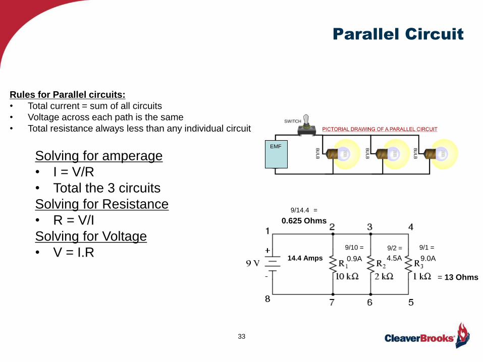
Parallel Circuit
33
EMF
0.9A 4.5A 9.0A14.4 Amps
0.625 Ohms
Solving for amperage
• I = V/R
• Total the 3 circuits
Solving for Resistance
• R = V/I
Solving for Voltage
• V = I.R
Rules for Parallel circuits:
• Total current = sum of all circuits
• Voltage across each path is the same
• Total resistance always less than any individual circuit
= 13 Ohms
9/10 = 9/2 = 9/1 =
9/14.4 =

Starters & Contactors
34
Starter Contactor

Relays & Timers
35
Relays
Timer

Transformers
36
220/120V
120/24V
10,000V

The Burner Management System (BMS)
37

Switchman
38

Burner Management System
39
• Switchman
• Train engineer

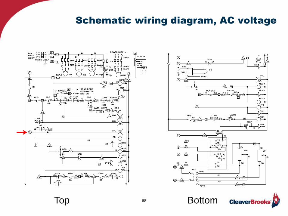
Schematic wiring diagram, AC voltage
40Top Bottom
Hot
sideNeutral
Side

Flame Safeguard System
Sequence
“The Switchman”
Control circuit power applied.…………………...Circuits 4 & 5
Power enters…………………….……………………...4,L2
Limit circuit………………………………………………4,6
Pre-ignition interlock…………………..………….....4,20
Blower motor coil energized……………………….5
Modulating damper motor closed proof.……….13,14
Drive damper full open….…………………………….13,12
Combustion air proof…………………………………..7
Drive damper to low fire position………………….13,14
Ignition pilot………….……………………………………8
Flame proven (10 sec proof)..……………………….F,G
Open main gas valve(s)………………………………..9
Release to modulation………………………………..13,15
Alarms……………………………………………………….3
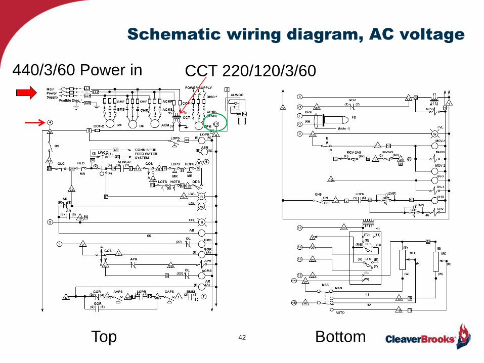
Schematic wiring diagram, AC voltage
42Top Bottom
440/3/60 Power in CCT 220/120/3/60

Burner Management System
Sequence
Control circuit power applied.…………………...Circuits 4 & 5
Power enters…………………….……………………...4,L2
Limit circuit………………………………………………4,6
Pre-ignition interlock…………………..………….....4,20
Blower motor coil energized……………………….5
Modulating damper motor closed proof.……….13,14
Drive damper full open….…………………………….13,12
Combustion air proof…………………………………..7
Drive damper to low fire position………………….13,14
Ignition pilot………….……………………………………8
Flame proven (10 sec proof)..……………………….F,G
Open main gas valve(s)………………………………..9
Release to modulation………………………………..13,15
Alarms……………………………………………………….3

Schematic wiring diagram, AC voltage
44Top Bottom
Limit circuit

Burner Management System
Sequence
Control circuit power applied.…………………...Circuits 4 & 5
Power enters…………………….……………………...4,L2
Limit circuit………………………………………………4,6
Pre-ignition interlock…………………..………….....4,20
Blower motor coil energized……………………….5
Modulating damper motor closed proof.……….13,14
Drive damper full open….…………………………….13,12
Combustion air proof…………………………………..7
Drive damper to low fire position………………….13,14
Ignition pilot………….……………………………………8
Flame proven (10 sec proof)..……………………….F,G
Open main gas valve(s)………………………………..9
Release to modulation………………………………..13,15
Alarms……………………………………………………….3
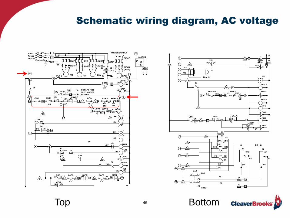
Schematic wiring diagram, AC voltage
46Top Bottom

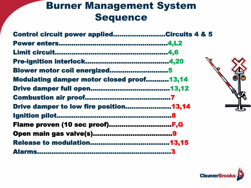
Burner Management System
Sequence
Control circuit power applied.…………………...Circuits 4 & 5
Power enters…………………….……………………...4,L2
Limit circuit………………………………………………4,6
Pre-ignition interlock…………………..………….....4,20
Blower motor coil energized……………………….5
Modulating damper motor closed proof.……….13,14
Drive damper full open….…………………………….13,12
Combustion air proof…………………………………..7
Drive damper to low fire position………………….13,14
Ignition pilot………….……………………………………8
Flame proven (10 sec proof)..……………………….F,G
Open main gas valve(s)………………………………..9
Release to modulation………………………………..13,15
Alarms……………………………………………………….3
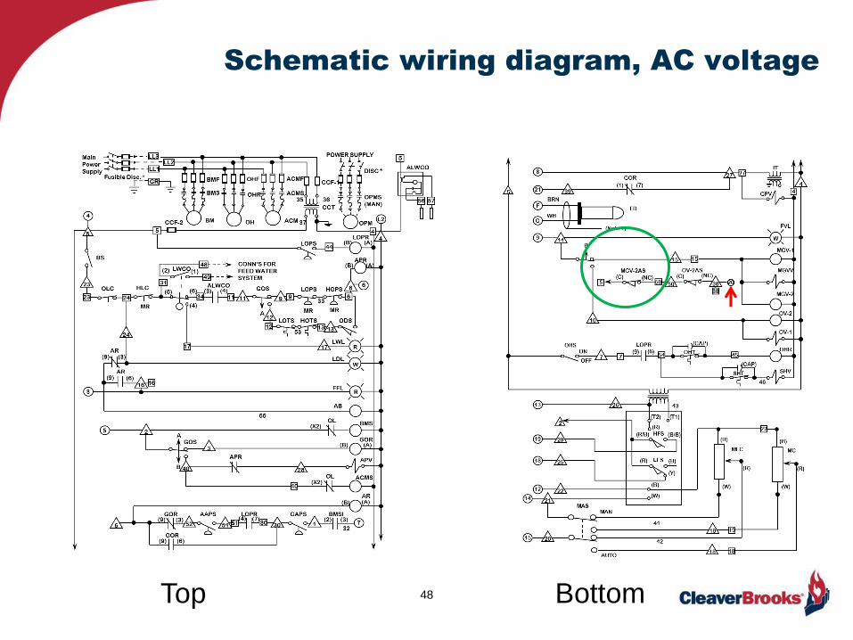
Schematic wiring diagram, AC voltage
48Top Bottom

Burner Management System
Sequence
Control circuit power applied.…………………...Circuits 4 & 5
Power enters…………………….……………………...4,L2
Limit circuit………………………………………………4,6
Pre-ignition interlock…………………..………….....4,20
Blower motor coil energized……………………….5
Modulating damper motor closed proof.……….13,14
Drive damper full open….…………………………….13,12
Combustion air proof…………………………………..7
Drive damper to low fire position………………….13,14
Ignition pilot………….……………………………………8
Flame proven (10 sec proof)..……………………….F,G
Open main gas valve(s)………………………………..9
Release to modulation………………………………..13,15
Alarms……………………………………………………….3

Schematic wiring diagram, AC voltage
50Top Bottom

Burner Management System
Sequence
Control circuit power applied.…………………...Circuits 4 & 5
Power enters…………………….……………………...4,L2
Limit circuit………………………………………………4,6
Pre-ignition interlock…………………..………….....4,20
Blower motor coil energized……………………….5
Modulating damper motor closed proof.……….13,14
Drive damper full open….…………………………….13,12
Combustion air proof…………………………………..7
Drive damper to low fire position………………….13,14
Ignition pilot………….……………………………………8
Flame proven (10 sec proof)..……………………….F,G
Open main gas valve(s)………………………………..9
Release to modulation………………………………..13,15
Alarms……………………………………………………….3

Schematic wiring diagram, AC voltage
52Top Bottom
120/24V

Burner Management System
Sequence
Control circuit power applied.…………………...Circuits 4 & 5
Power enters…………………….……………………...4,L2
Limit circuit………………………………………………4,6
Pre-ignition interlock…………………..………….....4,20
Blower motor coil energized……………………….5
Modulating damper motor closed proof.……….13,14
Drive damper full open….…………………………….13,12
Combustion air proof…………………………………..7
Drive damper to low fire position………………….13,14
Ignition pilot………….……………………………………8
Flame proven (10 sec proof)..……………………….F,G
Open main gas valve(s)………………………………..9
Release to modulation………………………………..13,15
Alarms……………………………………………………….3
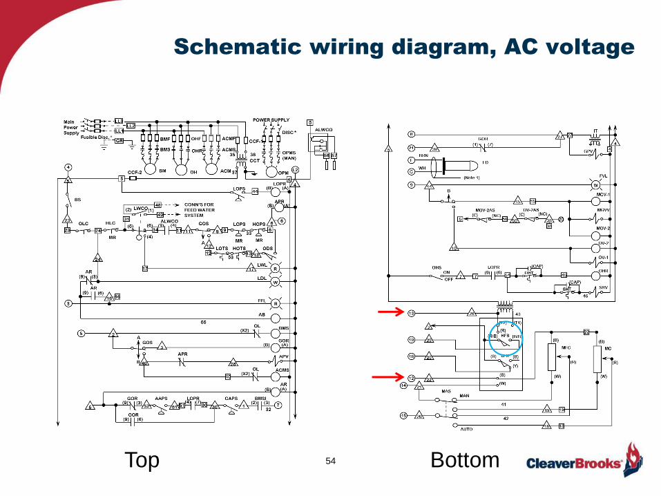
Schematic wiring diagram, AC voltage
54Top Bottom
Burner Management System
Sequence
Control circuit power applied.…………………...Circuits 4 & 5
Power enters…………………….……………………...4,L2
Limit circuit………………………………………………4,6
Pre-ignition interlock…………………..………….....4,20
Blower motor coil energized……………………….5
Modulating damper motor closed proof.……….13,14
Drive damper full open….…………………………….13,12
Combustion air proof…………………………………..7
Drive damper to low fire position………………….13,14
Ignition pilot………….……………………………………8
Flame proven (10 sec proof)..……………………….F,G
Open main gas valve(s)………………………………..9
Release to modulation………………………………..13,15
Alarms……………………………………………………….3

Schematic wiring diagram, AC voltage
56Top Bottom

Burner Management System
Sequence
Control circuit power applied.…………………...Circuits 4 & 5
Power enters…………………….……………………...4,L2
Limit circuit………………………………………………4,6
Pre-ignition interlock…………………..………….....4,20
Blower motor coil energized……………………….5
Modulating damper motor closed proof.……….13,14
Drive damper full open….…………………………….13,12
Combustion air proof…………………………………..7
Drive damper to low fire position………………….13,14
Ignition pilot………….……………………………………8
Flame proven (10 sec proof)..……………………….F,G
Open main gas valve(s)………………………………..9
Release to modulation………………………………..13,15
Alarms……………………………………………………….3
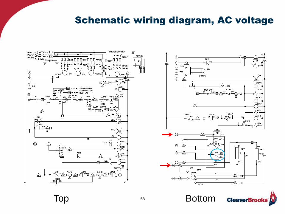
Schematic wiring diagram, AC voltage
58Top Bottom
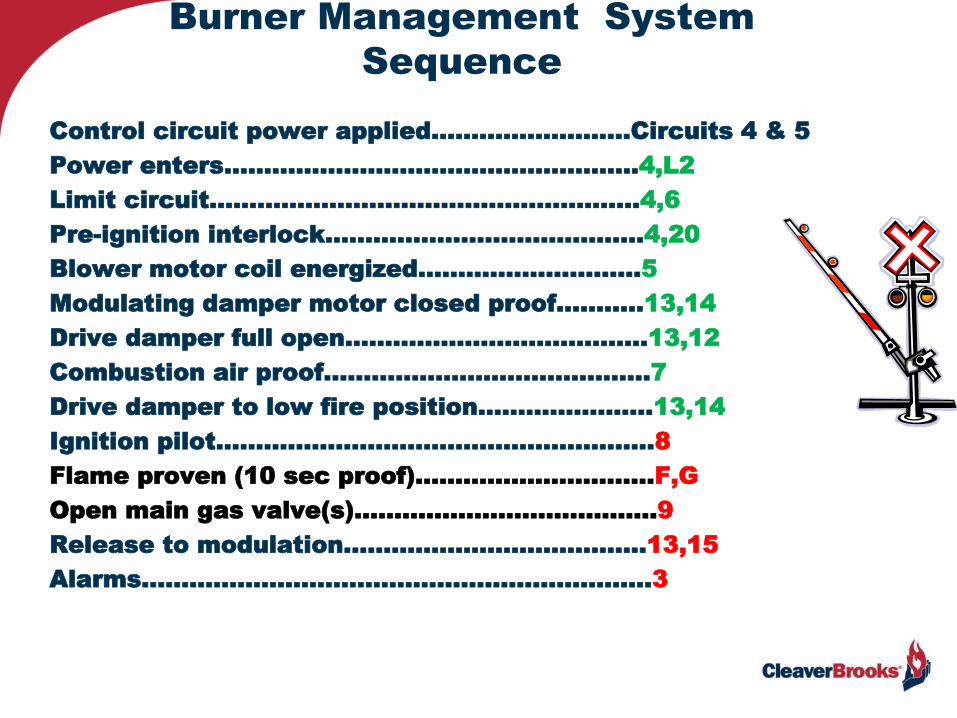
Burner Management System
Sequence
Control circuit power applied.…………………...Circuits 4 & 5
Power enters…………………….……………………...4,L2
Limit circuit………………………………………………4,6
Pre-ignition interlock…………………..………….....4,20
Blower motor coil energized……………………….5
Modulating damper motor closed proof.……….13,14
Drive damper full open….…………………………….13,12
Combustion air proof…………………………………..7
Drive damper to low fire position………………….13,14
Ignition pilot………….……………………………………8
Flame proven (10 sec proof)..……………………….F,G
Open main gas valve(s)………………………………..9
Release to modulation………………………………..13,15
Alarms……………………………………………………….3
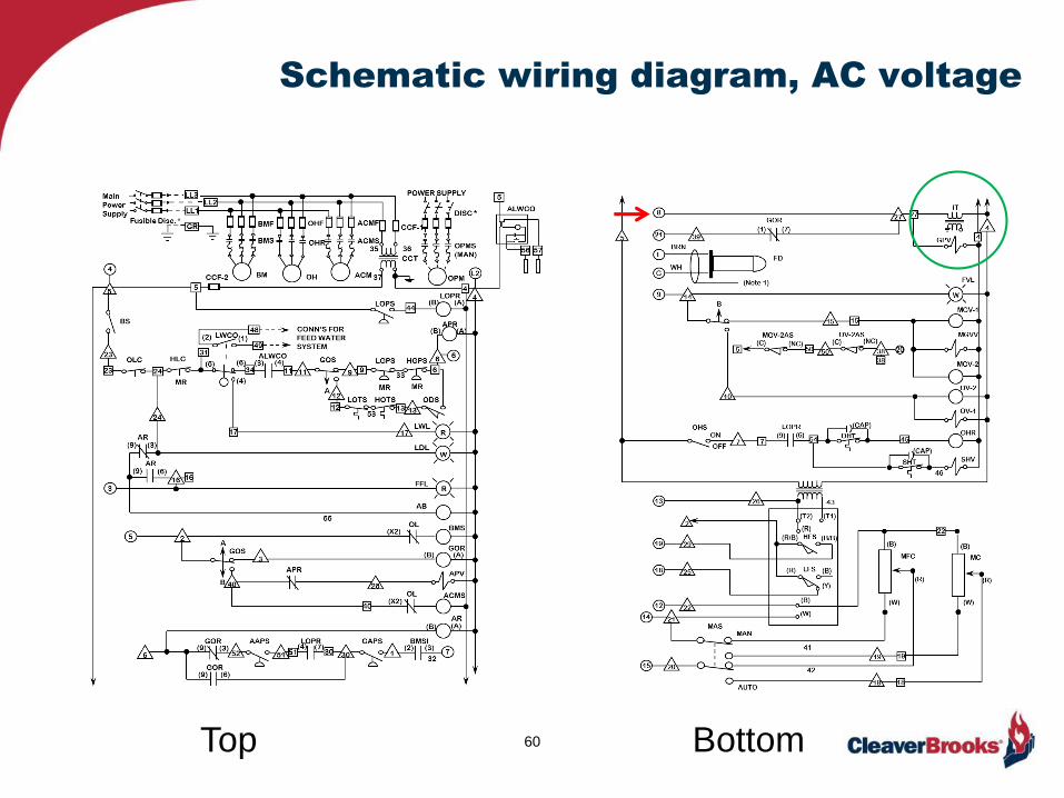
Schematic wiring diagram, AC voltage
60Top Bottom

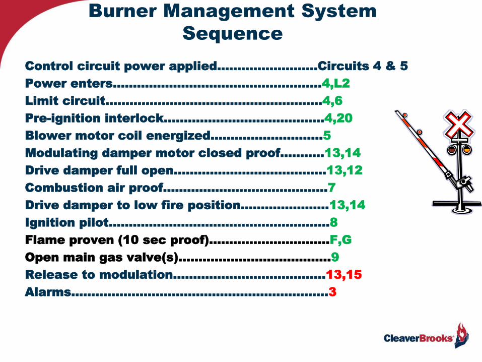
Burner Management System
Sequence
Control circuit power applied.…………………...Circuits 4 & 5
Power enters…………………….……………………...4,L2
Limit circuit………………………………………………4,6
Pre-ignition interlock…………………..………….....4,20
Blower motor coil energized……………………….5
Modulating damper motor closed proof.……….13,14
Drive damper full open….…………………………….13,12
Combustion air proof…………………………………..7
Drive damper to low fire position………………….13,14
Ignition pilot………….……………………………………8
Flame proven (10 sec proof)..……………………….F,G
Open main gas valve(s)………………………………..9
Release to modulation………………………………..13,15
Alarms……………………………………………………….3

Schematic wiring diagram, AC voltage
62Top Bottom

Burner Management System
Sequence
Control circuit power applied.…………………...Circuits 4 & 5
Power enters…………………….……………………...4,L2
Limit circuit………………………………………………4,6
Pre-ignition interlock…………………..………….....4,20
Blower motor coil energized……………………….5
Modulating damper motor closed proof.……….13,14
Drive damper full open….…………………………….13,12
Combustion air proof…………………………………..7
Drive damper to low fire position………………….13,14
Ignition pilot………….……………………………………8
Flame proven (10 sec proof)..……………………….F,G
Open main gas valve(s)………………………………..9
Release to modulation………………………………..13,15
Alarms……………………………………………………….3

Schematic wiring diagram, AC voltage
64Top Bottom
Burner Management System
Sequence
Control circuit power applied.…………………...Circuits 4 & 5
Power enters…………………….……………………...4,L2
Limit circuit………………………………………………4,6
Pre-ignition interlock…………………..………….....4,20
Blower motor coil energized……………………….5
Modulating damper motor closed proof.……….13,14
Drive damper full open….…………………………….13,12
Combustion air proof…………………………………..7
Drive damper to low fire position………………….13,14
Ignition pilot………….……………………………………8
Flame proven (10 sec proof)..……………………….F,G
Open main gas valve(s)………………………………..9
Release to modulation………………………………..13,15
Alarms……………………………………………………….3

Schematic wiring diagram, AC voltage
66Top Bottom

Burner Management System
Sequence
Control circuit power applied.…………………...Circuits 4 & 5
Power enters…………………….……………………...4,L2
Limit circuit………………………………………………4,6
Pre-ignition interlock…………………..………….....4,20
Blower motor coil energized……………………….5
Modulating damper motor closed proof.……….13,14
Drive damper full open….…………………………….13,12
Combustion air proof…………………………………..7
Drive damper to low fire position………………….13,14
Ignition pilot………….……………………………………8
Flame proven (10 sec proof)..……………………….F,G
Open main gas valve(s)………………………………..9
Release to modulation………………………………..13,15
Alarms……………………………………………………….3
Schematic wiring diagram, AC voltage
68Top Bottom

24
(5)
LW/FFA with Alarm Silencing Switch
Boiler On Line 4
4
FFL
LWL
AB
R
LDLW
R
CR-1(6)(9)
CR-1(9)(3)
17
17
3
3149
24
OLC HLC
MR
(2) (1)
(4)
(6)
48LWCO
CONN’S FOR
FEED WATER
SYSTEM
34
16
CR-1(B) (A)
55
CR-2
(3)(9)
CR-2
(6)(9)
CR-2(B) (A)
ASS
(mom)

24
(5)
LW/FFA with Alarm Silencing Switch
Boiler Off Line 4
4
FFL
LWL
AB
R
LDLW
R
CR-1(6)(9)
CR-1(9)(3)
17
17
3
3149
24
OLC HLC
MR
(2) (1)
(4)
(6)
48LWCO
CONN’S FOR
FEED WATER
SYSTEM
34
16
CR-1(B) (A)
55
CR-2
(3)(9)
CR-2
(6)(9)
CR-2(B) (A)
ASS
(mom)

24
(5)
LW Alarm4
4
FFL
LWL
AB
R
LDLW
R
CR-1(6)(9)
CR-1(9)(3)
17
17
3
3149
24
OLC HLC
MR
(2) (1)
(4)
(6)
48LWCO
CONN’S FOR
FEED WATER
SYSTEM
34
16
CR-1(B) (A)
55
CR-2
(3)(9)
CR-2
(6)(9)
CR-2(B) (A)
ASS
(mom)
Relay

24
(5)
LW with Alarm 4
4
FFL
LWL
AB
R
LDLW
R
CR-1(6)(9)
CR-1(9)(3)
17
17
3
3149
24
OLC HLC
MR
(2) (1)
(4)
(6)
48LWCO
CONN’S FOR
FEED WATER
SYSTEM
34
16
CR-1(B) (A)
55
CR-2
(3)(9)
CR-2
(6)(9)
CR-2(B) (A)
ASS
(mom)
Relay

Schematic wiring diagram, AC voltage
73Top Bottom
Hot
sideNeutral
Side

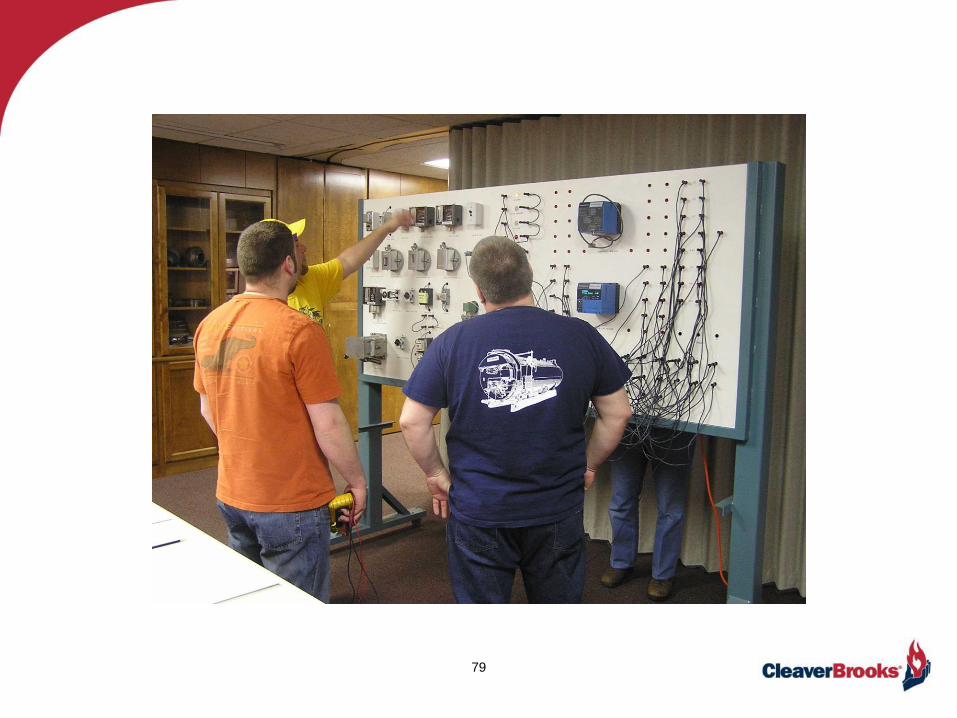
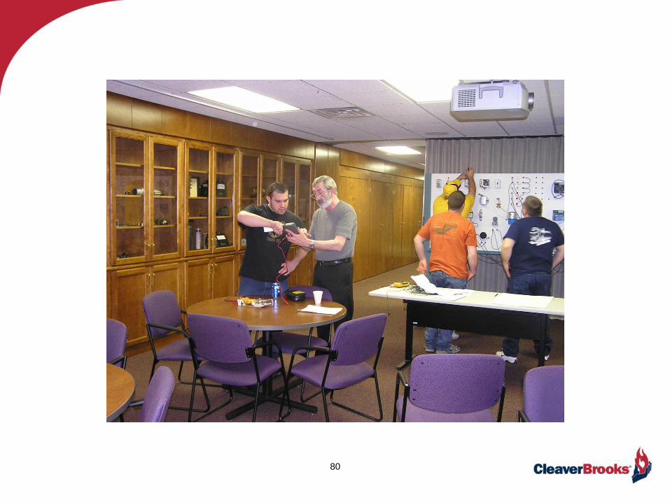
Knowledge is Power
Boiler outage & Un$cheduled downtime!

75
Knowledge is Power!

76
• At our facility
• At your facility
• On-line

77

78
79
80

81
Summary
• Electricity is the flow of electrons from more to less potential.
• Direct current is unidirectional and cannot be transformed.
• Alternating current moves in both directions above and below the zero volt horizontal
in a sinusoidal curve.
• AC can be transformed to increase and decrease voltage.
• Voltage is the electrical potential difference between two points and also referred to as
Electromotive Force (EMF).
• An ampere is the measurement unit used to determine the flow of current.
• Watt is the standard of unit power where a current of 1 ampere flows across a potential
difference of 1 volt.
• Ohm’s law for voltage is E = I.R
• Neutral is also known as the “common” which completes the circuit.
• Ground is a direct physical connection to earth for safety purposes and should not carry
current.
• Three phase power is also known as polyphase with 3 separate current supplies coming
into one connector.
• A schematic wiring diagram shows point to point connections, but not the logic of the
sequencing.
• The BMS provides the sequence for energizing the proper circuits for safe and reliable
boiler operation.
• Electricity is complicated, and requires training for adequate understanding.