Embed Size (px)
Citation preview
BRAJANATH DEY
(Meter Testing Laboratory)
TATA Power - DDL
23rd Nov. 2017
Basic Energy Metering
TYPES OF METERS AND ITS Testing
Meter Tampering

What is Energy METER ?
An electricity energy meter is a device that measures the
amount of ELECTRIC ENERGY consumed by any premises .
Energy meter operates by continuous measuring of the
instantaneous electrical parameters like VOLTAGE,
CURRENT, PF, Frequency etc. and calculate them to give
instantaneous ELECTRIC POWER which is then
INTEGRATED against time to give an ENERGY consumption.
Energy meters are typically calibrated in term of billing units
that is most commonly known as kilowatt hour.
kWh is equal to the amount of energy consumed by a load of
one kilowatt over a period of one hour that is equal to 1000
watt or 3,600,000 joules or 01 unit or 01 kWh
P = V I Cosθ ;
E = ∫ V I Cosθ.∂t

RTC
Voltage
Sensor
Current
Sensor
Multi
plierADC
Block Diagram of Electronic Energy Meter
DISPLAY
Memory
Micro
Controller
Analog to digital converter Optical Port Push Button

Review of fundamental electrical concepts
Active Energy (unit kWh)
V X I X Cos θ
Reactive Energy (unit kVArh)
V X I X Sinθ
Apparent Energy (unit kVAh)
V X I
Where,
V is line volt,
I is line current ,
θ is phase angle between volt and current ,
Cos θ is power factor
Single Phase
• Vp X Ip X cos θ
Three Phase
• 3 Phase 4 Wire 3 x Vp X Ip X cos θ
• 3 Phase 3 Wire √3 x VL X IL X cos θ

Methods of Sensing of Voltage & Current for Energy Measurement

Single Phase Electronic Whole Current Meters
Shunt Circuit (Voltage Coil)/CT Circuit (Current Coil) Meter without CT

3-Ph, 4-Wire CT Unit & Meter / Whole Current Meter
Incoming Terminals
Outgoing Terminals
Modem
Resin Cast CT Unit
Optical Port
Meter Display
Calibration LED
Name Plate
Terminal Block

CT Unit
8
CT & PTPins
CTRatio
Modem Connection
Outing Terminals
Incoming Terminals

Indoor type HT Metering Cubicle with inbuilt resin cast CT & PT
Control Cables
CT PT Unit

Outdoor type HT Metering Cubicle with CT PT Unit

SPECIFICATION STATIC METERS CONVENTIONAL ELECTRO-
MECHANICAL METERS
Life Sustainable accuracy life-over 5 years Limited life
Wear & Tear No wear & tear Lot of wear & tear Meter becomes
slow with time
Hanging of Meter Measures accurately under any conditions. Accuracy is effected with change in
angle of hanging
Protection Fully protected in case of wrong connection Get damaged with wrong
connections
Tampered Measures accurately in various Tampered
conditions
- Reverse Tamper
- Earth Tamper
- Immune to DC influence
- Distributed phase sequence
Meters either do not records in
tampered conditions or even
start running in reverse
condition
Power Loss in voltage
Circuit is continuous
& is unmetered
Loss in Voltage Circuit of Electronic meter is
low
Loss in Voltage circuit of
Conventional Meters is high
WHY ELECTRONIC METERS ???
Types of meters & Ratings of Energy
Meters
Type of Meter
Installed
Class Rating of Conventional
Meters Installed
Applied Load
Factor
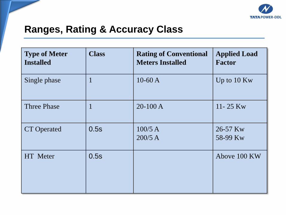
Single phase 1 10-60 A Up to 10 Kw
Three Phase 1 20-100 A 11- 25 Kw
CT Operated 0.5s 100/5 A
200/5 A
26-57 Kw
58-99 Kw
HT Meter 0.5s Above 100 KW
Ranges, Rating & Accuracy Class
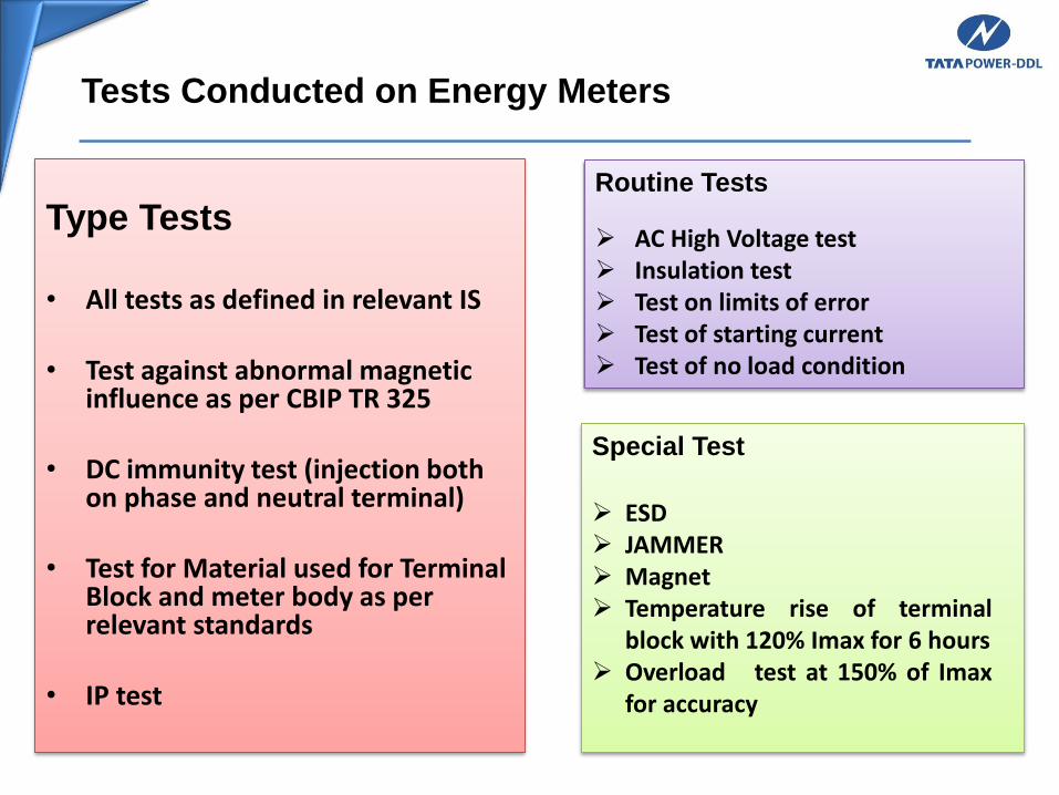
Tests Conducted on Energy Meters
Type Tests
• All tests as defined in relevant IS
• Test against abnormal magnetic influence as per CBIP TR 325
• DC immunity test (injection both on phase and neutral terminal)
• Test for Material used for Terminal Block and meter body as per relevant standards
• IP test
Routine Tests
AC High Voltage test Insulation test Test on limits of error Test of starting current Test of no load condition
Special Test
ESD JAMMER Magnet Temperature rise of terminal
block with 120% Imax for 6 hours Overload test at 150% of Imax
for accuracy

Tests Conducted on Energy Meters
120% I max(120A) I max (100A) Ib(20A) 0.5 Ib (10A) 0.1Ib (2A) 0.05Ib (1A)
UPF, 0.8 lead and
0.5 lag
UPF, 0.8 lead
and 0.5 lag
UPF, 0.8 lead
and 0.5 lag
UPF, 0.8 lead
and 0.5 lag
UPF, 0.8 Lead and
0.5 lag
UPF
Acceptance Test
AC High Voltage test
Insulation test
Test on limits of error with following loads
Test of meter constant
Test of starting current
Test of no load condition
Test of repeatability of error.
Test of power consumption.
Test for Immunity against external influencing signal as per the TATA POWER-DDL specification
Test for Immunity against DC Immunity as per the TATA POWER-DDL specification
Test for Immunity against Tamper conditions 38 tampers as per the TATA POWER-DDL specification
Error measurements with all abnormal condition along with ESD and magnet
Test to Influence of Harmonics
Supply voltage and frequency variation test
Testing of self-diagnostic features
All tamper tests, count increment and logging with date and time

Different types of meters & Modems

Type of Energy Meters
1-ph, 2 Wire Meter Whole Current Meter
3-ph, 4-Wire Whole Current Meter
3-ph, 4-Wire CT Operated Meter
3-ph, 3- Wire HT Meter
3-ph, 4-Wire HT Meter
DT Meter
Feeder Meter
Consumer Meter
Pre-Paid Meter
Post Paid Meter
Smart Meter
Net Meter

Evaluation of Single Phase Whole Current Electronic or Static
Energy Meters
Liquid Crystal Display (LCD)Semi-digital
Latest Postpaid Meters Pre-paid metering

Meter Reading Instruments & Modems Used in TPDDL
DMRI
CMRI
Modem

Static Energy Meter with data
transfer capabilities
Components Used for AMR & Individual Meter Vendor Software
TRANSMISSION
MEDIUM
MODEM
Software &
Systems
for data
Collection
and
processing
BCS
L&T ABBSECURE
GSM
Modem
GSM
Modem
GSM
Modem
L&TSECURE ABB

Dishonest Abstraction of Energy (DAE) – Theft by meter tampering and
its detection
DAE and its detection
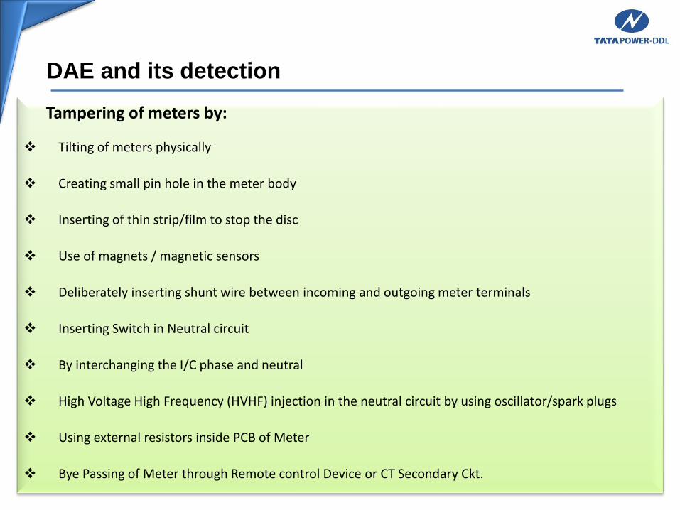
Tampering of meters by:
Tilting of meters physically
Creating small pin hole in the meter body
Inserting of thin strip/film to stop the disc
Use of magnets / magnetic sensors
Deliberately inserting shunt wire between incoming and outgoing meter terminals
Inserting Switch in Neutral circuit
By interchanging the I/C phase and neutral
High Voltage High Frequency (HVHF) injection in the neutral circuit by using oscillator/spark plugs
Using external resistors inside PCB of Meter
Bye Passing of Meter through Remote control Device or CT Secondary Ckt.

Physical Tampering – Double Shunt
PHYSICAL TAMPERING IN SINGLE PHASE METERS BY INSERTING SHUNT WIRE
SHUNTS IMPLANTED AT THE REAR OF SP STATIC METER

Physical Tampering – Single Shunt
PHYSICAL TAMPERING IN SINGLE PHASE METERS BY INSERTING SHUNT WIRE
SINGLE SHUNT NEUTRAL WIRE OF METER REMOVED AND EARTHED

Physical Tampering
PHYSICAL TAMPERING IN SINGLE PHASE METERS BY EARTHING THE NEUTRAL WIRE
IN SINGLE SHUNT CASES, NEUTRAL IS GROUNDED VIA A TWO WAY SWITCH

Physical Tampering – Resistors with PCB
PHYSICAL TAMPERING IN SINGLE PHASE METERS BY INSERTING EXTERNAL RESISTORS
EXTERNAL RESISTORS IN METER PCB CIRCUIT

Physical Tampering – Re-Soldering on PCB
PHYSICAL TAMPERING IN SINGLE PHASE & THREE PHASE METERS BY RE-SOLDERING ON PCB
RESISTOR REMOVED AND RE-FIXED; RE-SET SOLDER MARKS

TAMPERING IN SINGLE PHASE METERS BY INSERTING MAGNETIC SENSOR
MAGNETIC PROXIMITY SENSOR SWITCH WAS DETECTED.
A MAGNETIC PROXIMITY SWITCH IS A DEVICE WHICH SWITCHES ON IN THE PRESENCE OF A MAGNET.
IN THIS CASE, THE SWITCH WAS DISCONNECTING THE POWER SUPPLY TO THE METER CIRCUIT
Physical Tampering

Physical Tampering – Hole on Meter Body
PHYSICAL TAMPERING IN SINGLE PHASE METERS BY CREATING HOLE ON METER BODY
HOLES ON DIFFERENT PARTS OF THE METER BODY
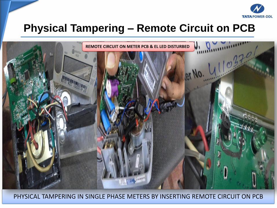
Physical Tampering – Remote Circuit on PCB
PHYSICAL TAMPERING IN SINGLE PHASE METERS BY INSERTING REMOTE CIRCUIT ON PCB
REMOTE CIRCUIT ON METER PCB & EL LED DISTURBED

Dishonest Abstraction of Energy (DAE)
METER DATA TAMPERING
TAMPERING IN THREE PHASE METERS BY JAMMER CIRCUIT
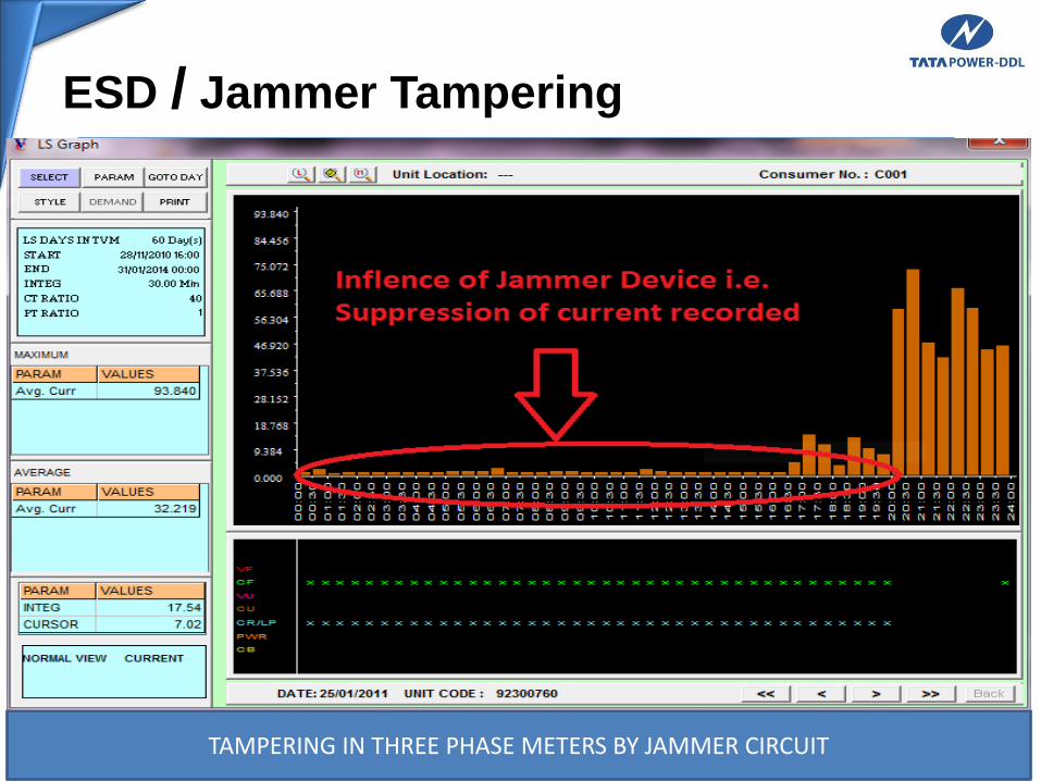
ESD / Jammer Tampering
TAMPERING IN THREE PHASE METERS BY JAMMER CIRCUIT
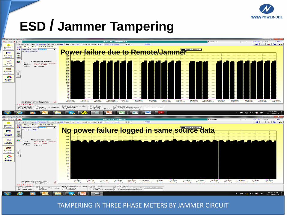
ESD / Jammer Tampering
Power failure due to Remote/Jammer
No power failure logged in same source data
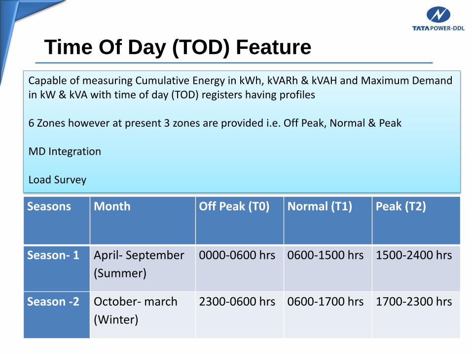
Time Of Day (TOD) Feature
Seasons Month Off Peak (T0) Normal (T1) Peak (T2)
Season- 1 April- September
(Summer)
0000-0600 hrs 0600-1500 hrs 1500-2400 hrs
Season -2 October- march
(Winter)
2300-0600 hrs 0600-1700 hrs 1700-2300 hrs
Capable of measuring Cumulative Energy in kWh, kVARh & kVAH and Maximum Demand in kW & kVA with time of day (TOD) registers having profiles
6 Zones however at present 3 zones are provided i.e. Off Peak, Normal & Peak
MD Integration
Load Survey

Metering Standard:
IS13779:1999: AC Static Watthour Meters, Class 1.0 and 2.0
IS14697:1999: AC Static Transformer operated Watthour and VAR hour meters, Class 0.2 and 0.5
IS16444:2015: AC Static Direct Connected Watthour Smart Meter Class 1 & 2 –Specification
IS15884:2010: AC direct connected static Prepayment Meter for active Energy
CBIP-88/304/325: CBIP specification of ac Static Electricity Energy Meter
IS15959:2011: Data exchange for electricity meter reading, tariff and load control-companion specification
IS12346: Testing Equipment for AC Electrical Energy Meters
IS15707: Testing, Evaluation, installation and maintenance