Embed Size (px)
Citation preview
BASIC INSTRUCTIONS
“SHIFTER” KZ1 / KZ2 e “X30 SHIFTER-TaG”
1
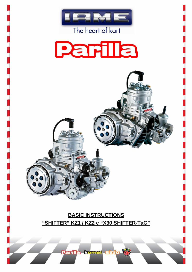
• FEEDING: by fuel mixture 98NO (min. 95NO) and 4% oil (CIK homologated).
ATTENTION: the engine is supplied without oil in the gearbox.
• GEARBOX OIL CHARGING: before using, fill with approx. 300÷330ml SAE 10W50 oil, through
the charging hole (A). • GEARBOX OIL DISCHARGING: remove the drain plug (B) to discharge the oil, and inspect the
magnet in the plug for the presence of consistent metallic particles • COOLING SYSTEM CONNECTIONS:
Once the system is filled (with pure water), check the proper air breathing. We recommend the use of a 3 way-thermostat (as shown on the fig.). It is though possible to make a direct connection, removing the thermostat and the T-pipe fitting. ATTENTION: water cooling operation temperature limits: min. 50°C / max. 58°C
FROM HEAD PIPE FITTING
TO THE CRANKCASE
A
B
2
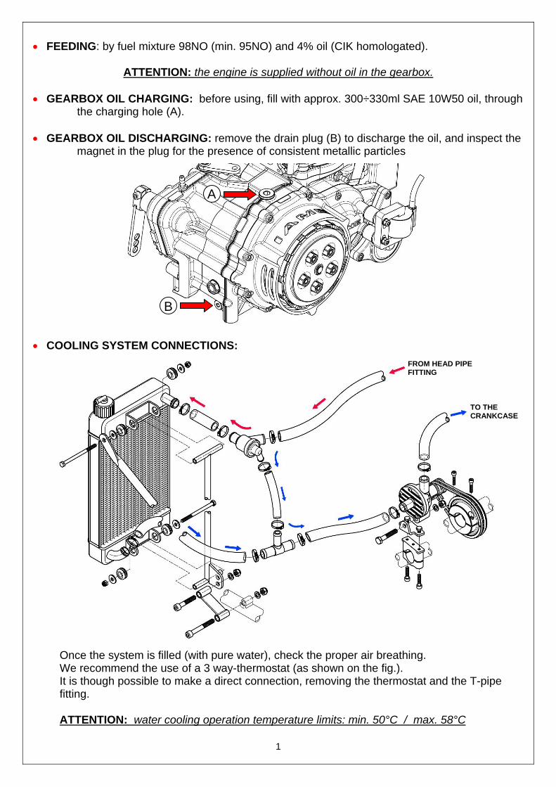
• ELECTRIC CONNECTIONS (X30 SHIFTER - TaG):
Wiring ground
Ignition connector
Coil ground
Coil connector Starter
connector
3
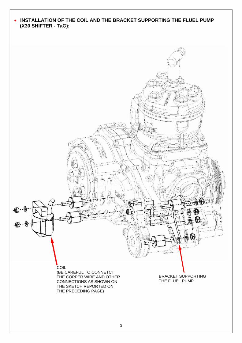
• INSTALLATION OF THE COIL AND THE BRACKET SUPPORTING THE FLUEL PUMP (X30 SHIFTER - TaG):
COIL (BE CAREFUL TO CONNETCT THE COPPER WIRE AND OTHER CONNECTIONS AS SHOWN ON THE SKETCH REPORTED ON THE PRECEDING PAGE)
BRACKET SUPPORTING THE FLUEL PUMP
4
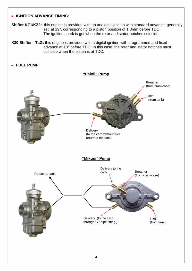
• IGNITION ADVANCE TIMING: Shifter KZ1/KZ2: this engine is provided with an analogic ignition with standard advance, generally set at 19°, corresponding to a piston position of 1.8mm before TDC. The ignition spark is got when the rotor and stator notches coincide. X30 Shifter - TaG: this engine is provided with a digital ignition with programmed and fixed
advance at 18° before TDC. In this case, the rotor and stator notches must coincide when the piston is at TDC.
• FUEL PUMP:
“Paioli” Pump
“Mikuni” Pump
Delivery (to the carb without fuel return to the tank)
Inlet (from tank)
Breather (from crankcase)
Breather (from crankcase)
Delivery to the carb.
inlet (from tank)
Delivery (to the carb. through "Y" pipe fitting )
Return to tank
5
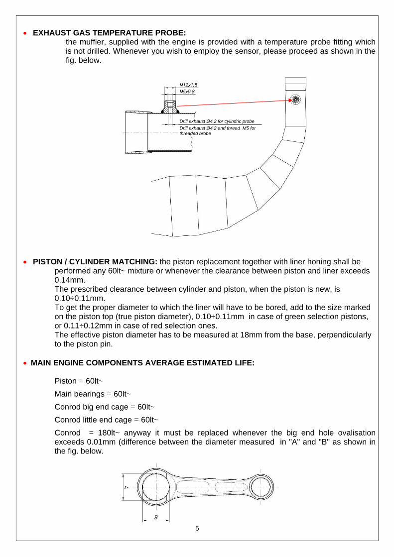
• EXHAUST GAS TEMPERATURE PROBE:
the muffler, supplied with the engine is provided with a temperature probe fitting which is not drilled. Whenever you wish to employ the sensor, please proceed as shown in the fig. below.
• PISTON / CYLINDER MATCHING: the piston replacement together with liner honing shall be
performed any 60lt~ mixture or whenever the clearance between piston and liner exceeds 0.14mm. The prescribed clearance between cylinder and piston, when the piston is new, is 0.10÷0.11mm. To get the proper diameter to which the liner will have to be bored, add to the size marked on the piston top (true piston diameter), 0.10÷0.11mm in case of green selection pistons, or 0.11÷0.12mm in case of red selection ones. The effective piston diameter has to be measured at 18mm from the base, perpendicularly to the piston pin.
• MAIN ENGINE COMPONENTS AVERAGE ESTIMATED LIFE:
Piston = 60lt~
Main bearings = 60lt~
Conrod big end cage = 60lt~
Conrod little end cage = 60lt~
Conrod = 180lt~ anyway it must be replaced whenever the big end hole ovalisation exceeds 0.01mm (difference between the diameter measured in "A" and "B" as shown in the fig. below.
Drill exhaust Ø4.2 for cylindric probe
Drill exhaust Ø4.2 and thread M5 for threaded probe
6
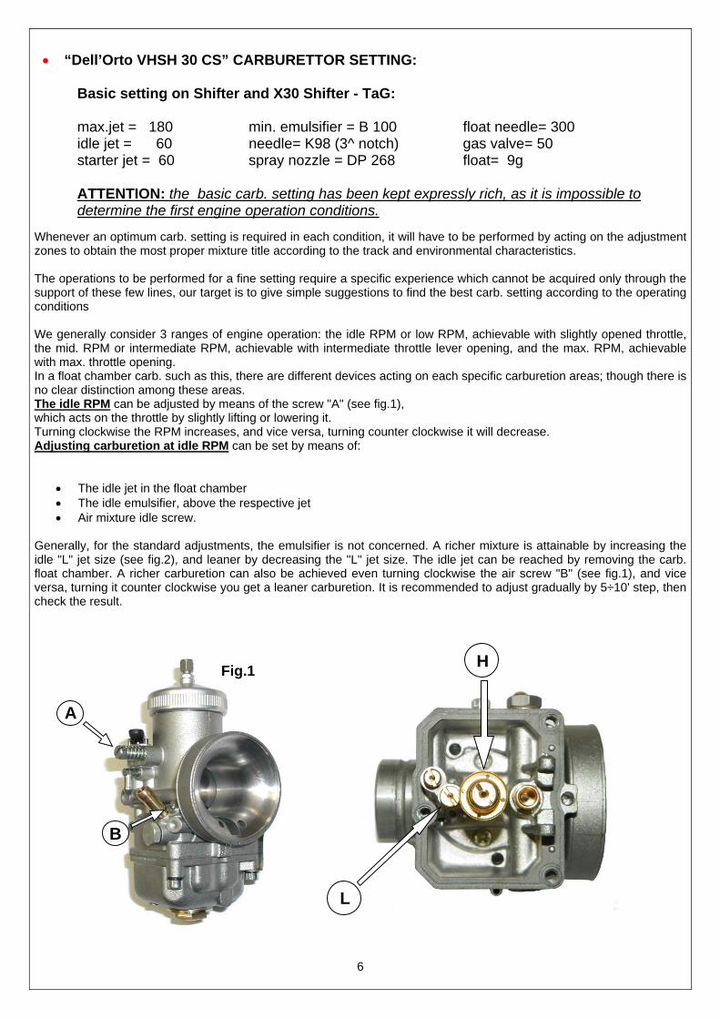
• “Dell’Orto VHSH 30 CS” CARBURETTOR SETTING: Basic setting on Shifter and X30 Shifter - TaG: max.jet = 180 min. emulsifier = B 100 float needle= 300 idle jet = 60 needle= K98 (3^ notch) gas valve= 50 starter jet = 60 spray nozzle = DP 268 float= 9g
ATTENTION: the basic carb. setting has been kept expressly rich, as it is impossible to determine the first engine operation conditions. Whenever an optimum carb. setting is required in each condition, it will have to be performed by acting on the adjustment zones to obtain the most proper mixture title according to the track and environmental characteristics. The operations to be performed for a fine setting require a specific experience which cannot be acquired only through the support of these few lines, our target is to give simple suggestions to find the best carb. setting according to the operating conditions We generally consider 3 ranges of engine operation: the idle RPM or low RPM, achievable with slightly opened throttle, the mid. RPM or intermediate RPM, achievable with intermediate throttle lever opening, and the max. RPM, achievable with max. throttle opening. In a float chamber carb. such as this, there are different devices acting on each specific carburetion areas; though there is no clear distinction among these areas. The idle RPM can be adjusted by means of the screw "A" (see fig.1), which acts on the throttle by slightly lifting or lowering it. Turning clockwise the RPM increases, and vice versa, turning counter clockwise it will decrease. Adjusting carburetion at idle RPM can be set by means of:
• The idle jet in the float chamber • The idle emulsifier, above the respective jet • Air mixture idle screw.
Generally, for the standard adjustments, the emulsifier is not concerned. A richer mixture is attainable by increasing the idle "L" jet size (see fig.2), and leaner by decreasing the "L" jet size. The idle jet can be reached by removing the carb. float chamber. A richer carburetion can also be achieved even turning clockwise the air screw "B" (see fig.1), and vice versa, turning it counter clockwise you get a leaner carburetion. It is recommended to adjust gradually by 5÷10' step, then check the result.
A
Fig.1
B
L
H
7
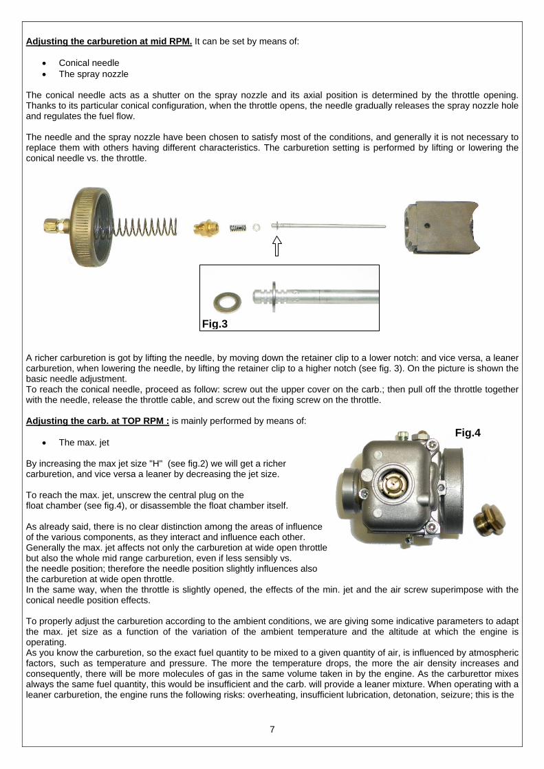
Adjusting the carburetion at mid RPM. It can be set by means of:
• Conical needle • The spray nozzle
The conical needle acts as a shutter on the spray nozzle and its axial position is determined by the throttle opening. Thanks to its particular conical configuration, when the throttle opens, the needle gradually releases the spray nozzle hole and regulates the fuel flow. The needle and the spray nozzle have been chosen to satisfy most of the conditions, and generally it is not necessary to replace them with others having different characteristics. The carburetion setting is performed by lifting or lowering the conical needle vs. the throttle. A richer carburetion is got by lifting the needle, by moving down the retainer clip to a lower notch: and vice versa, a leaner carburetion, when lowering the needle, by lifting the retainer clip to a higher notch (see fig. 3). On the picture is shown the basic needle adjustment. To reach the conical needle, proceed as follow: screw out the upper cover on the carb.; then pull off the throttle together with the needle, release the throttle cable, and screw out the fixing screw on the throttle. Adjusting the carb. at TOP RPM : is mainly performed by means of:
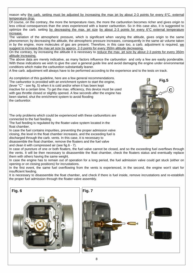
• The max. jet By increasing the max jet size "H" (see fig.2) we will get a richer carburetion, and vice versa a leaner by decreasing the jet size. To reach the max. jet, unscrew the central plug on the float chamber (see fig.4), or disassemble the float chamber itself. As already said, there is no clear distinction among the areas of influence of the various components, as they interact and influence each other. Generally the max. jet affects not only the carburetion at wide open throttle but also the whole mid range carburetion, even if less sensibly vs. the needle position; therefore the needle position slightly influences also the carburetion at wide open throttle. In the same way, when the throttle is slightly opened, the effects of the min. jet and the air screw superimpose with the conical needle position effects. To properly adjust the carburetion according to the ambient conditions, we are giving some indicative parameters to adapt the max. jet size as a function of the variation of the ambient temperature and the altitude at which the engine is operating. As you know the carburetion, so the exact fuel quantity to be mixed to a given quantity of air, is influenced by atmospheric factors, such as temperature and pressure. The more the temperature drops, the more the air density increases and consequently, there will be more molecules of gas in the same volume taken in by the engine. As the carburettor mixes always the same fuel quantity, this would be insufficient and the carb. will provide a leaner mixture. When operating with a leaner carburetion, the engine runs the following risks: overheating, insufficient lubrication, detonation, seizure; this is the
Fig.4
Fig.3
8
reason why the carb, setting must be adjusted by increasing the max jet by about 2-3 points for every 6°C. external temperature drop. Of course, on the contrary, the more the temperature rises, the more the carburetion becomes richer and gives origin to less critical consequences than the ones experienced with a leaner carburetion. So in this case also, it is suggested to optimize the carb. setting by decreasing the max. jet size by about 2-3 points for every 6°C external temperature increase. The variation of the atmospheric pressure, which is significant when varying the altitude, gives origin to the same phenomenon; by decreasing the altitude, the atmospheric pressure increases, consequently in the same air volume taken in by the engine, more molecules of gas are present. Therefore, in this case too, a carb. adjustment is required, we suggest to increase the max jet size by approx 2-3 points for every 350m altitude decreasing. On the contrary, by increasing the altitude it is necessary to reduce the max. jet size by about 2-3 points for every 350m altitude increasing. The above data are merely indicative, as many factors influence the carburetion and only a few are easily ponderable. With these indications we wish to give the user a general guide line and avoid damaging the engine under environmental conditions which make the carburetion substantially leaner. A fine carb. adjustment will always have to be performed according to the experience and to the tests on track. As completion of this guideline, here are a few general recommendations. The carburettor is provided with an enrichment system to start the engine, (lever "C" - see fig. 5) when it is cold and/or when it has been kept inactive for a certain time. To get the max. efficiency, this device must be used with gas throttle closed or slightly opened. A few seconds after the engine has been started, shut the enrichment system to avoid flooding the carburettor. The only problems which could be experienced with these carburettors are connected to the fuel feeding. The fuel feeding is regulated by the floater-valve system located in the float chamber. In case the fuel contains impurities, preventing the proper admission valve closing, the level in the float chamber increases, and the exceeding fuel is discharged through the carb. vents. In this case, it is necessary to disassemble the float chamber, remove the floaters and the fuel valve and clean it with compressed air (see fig.6 - 7). In case of puncture of one or both floaters, the fuel valve cannot be closed, and so the exceeding fuel overflows through the vents. It will be then necessary to disassemble the float chamber, check the floaters status and eventually replace them with others having the same weight. In case the engine has to remain out of operation for a long period, the fuel admission valve could get stuck (either on opening or on closing positions) for incrustations. In the first event, the same fuel overflowing from the vents is experienced, in the second, the engine won't start for insufficient feeding. It is necessary to disassemble the float chamber, and check if there is fuel inside, remove incrustations and re-establish the proper fuel admission through the floater-valve assembly.
Fig.5
C
Fig. 6 Fig. 7
9
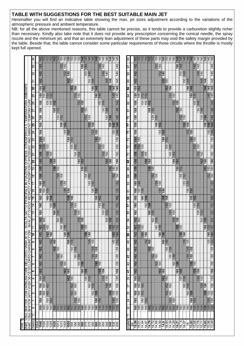
TABLE WITH SUGGESTIONS FOR THE BEST SUITABLE MAIN JET Hereinafter you will find an indicative table showing the max. jet sizes adjustment according to the variations of the atmospheric pressure and ambient temperature. NB: for all the above mentioned reasons, this table cannot be precise, as it tends to provide a carburetion slightly richer than necessary. Kindly also take note that it does not provide any prescription concerning the conical needle, the spray nozzle and the minimum jet, and that an extremely lean adjustment of these parts may void the safety margin provided by the table. Beside that, the table cannot consider some particular requirements of those circuits where the throttle is mostly kept full opened.