Embed Size (px)
Citation preview
Basic Laws
Instructor: Chia-Ming Tsai
Electronics Engineering
National Chiao Tung University
Hsinchu, Taiwan, R.O.C.

Contents
• Ohm’s Law (resistors)
• Nodes, Branches, and Loops
• Kirchhoff’s Laws
• Series Resistors and Voltage Division
• Parallel Resistors and Current Division
• Wye-Delta Transformations
• Applications
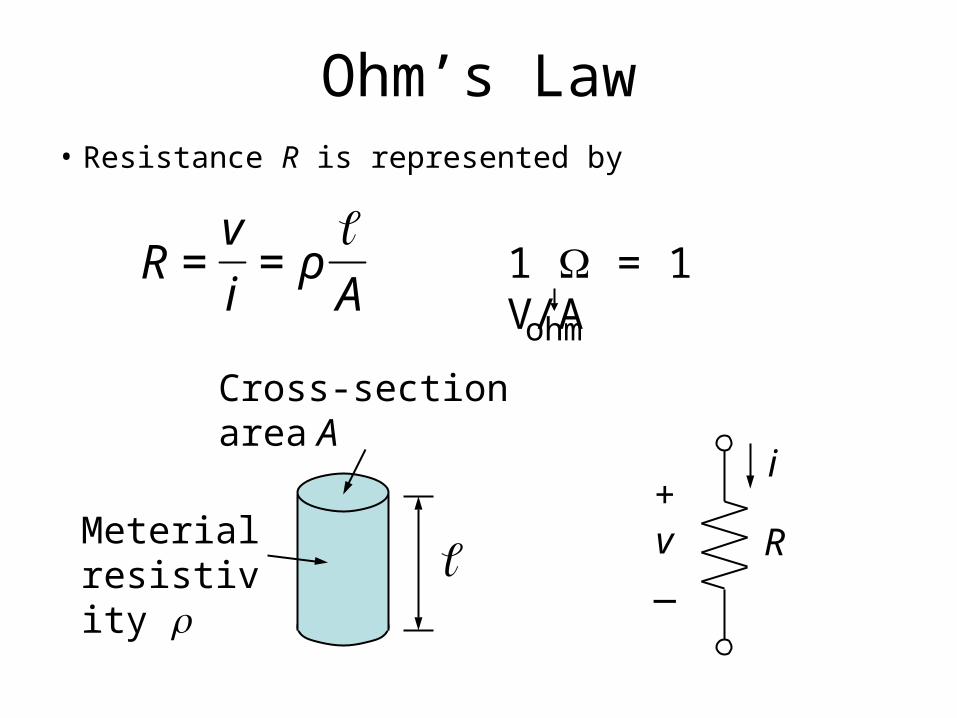
Ohm’s Law
• Resistance R is represented by
Aρ
i
vR
==
Rv+
_
i
1 = 1 V/A
Cross-sectionarea A
Meterialresistivity
ohm
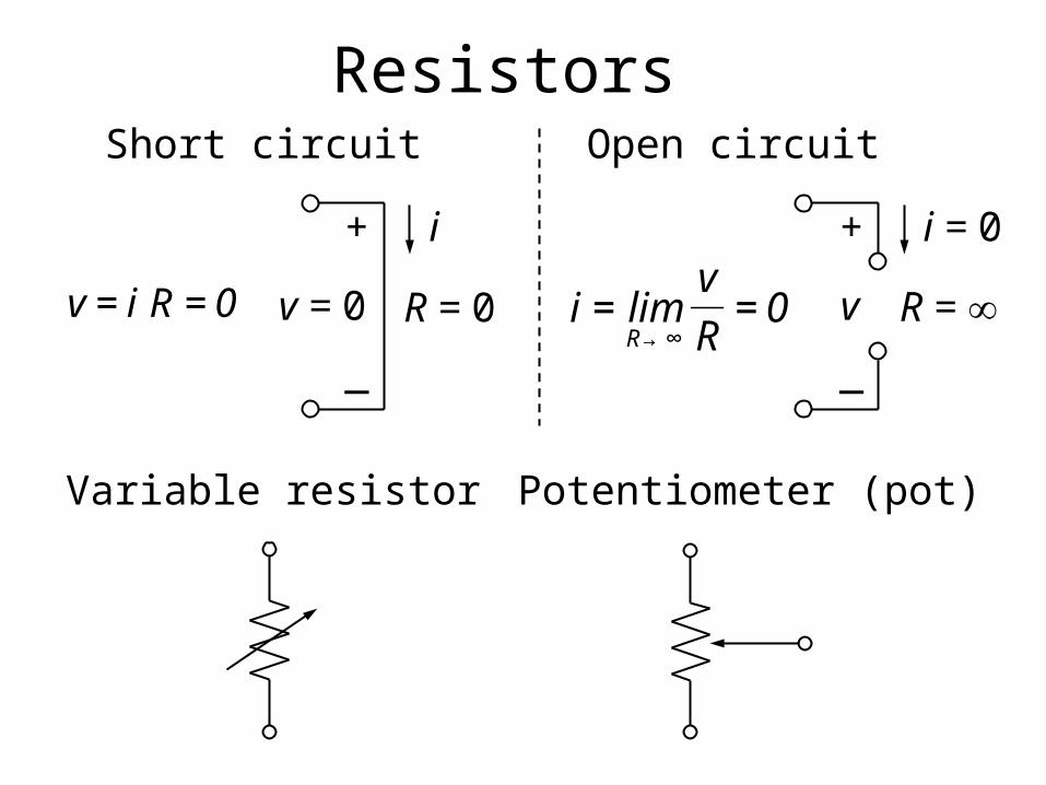
Resistors
0Riv == R = 0v = 0
+
_
i
R = v
+
_
i = 0
0R
vlimiR
==∞→
Variable resistor Potentiometer (pot)
Open circuitShort circuit
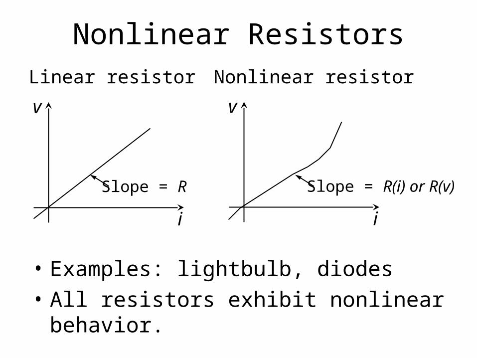
Nonlinear Resistors
i
v
Slope = R
v
i
Slope = R(i) or R(v)
Linear resistor Nonlinear resistor
• Examples: lightbulb, diodes
• All resistors exhibit nonlinear behavior.
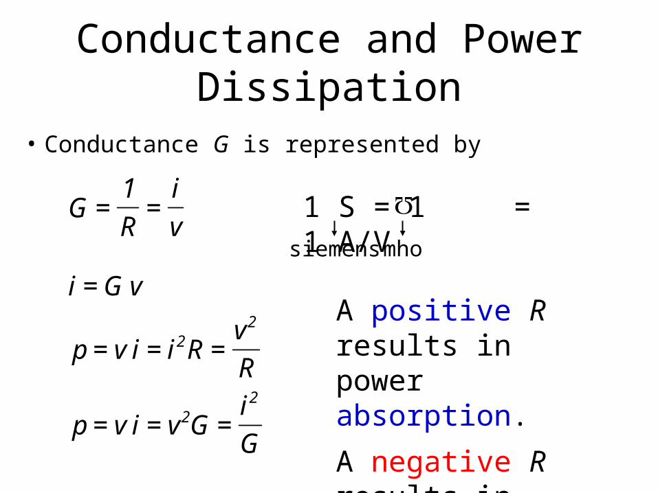
Conductance and Power Dissipation
• Conductance G is represented by
v
i
R
1G == 1 S = 1 = 1 A/V
siemens mho
G
iGvivp
R
vRiivp
vGi
22
22
===
===
=
A positive R results in power absorption.
A negative R results in power generation.
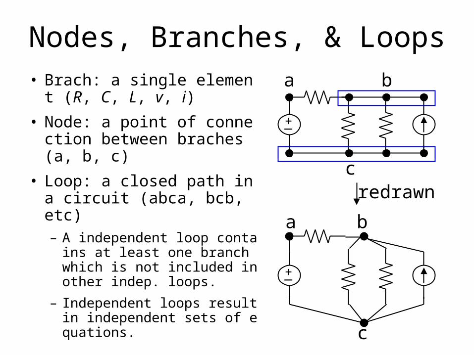
Nodes, Branches, & Loops• Brach: a single element (R,
C, L, v, i)
• Node: a point of connection between braches (a, b, c)
• Loop: a closed path in a circuit (abca, bcb, etc)– A independent loop contains a
t least one branch which is not included in other indep. loops.
– Independent loops result in independent sets of equations.
+_
a
c
b
+_
c
ba
redrawn
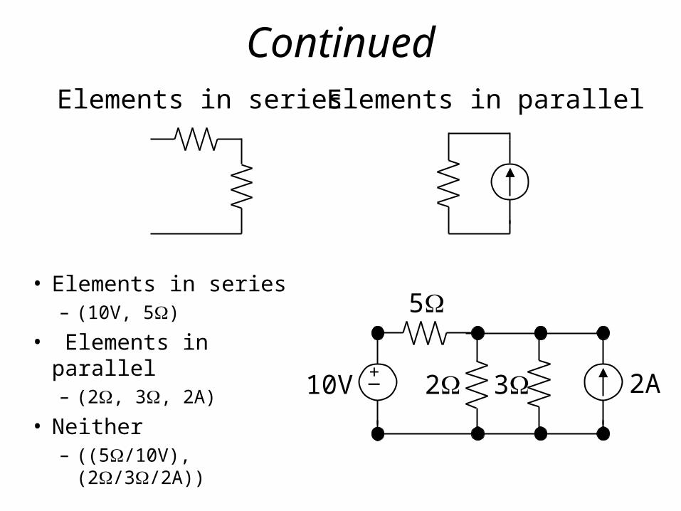
ContinuedElements in parallelElements in series
• Elements in series– (10V, 5)
• Elements in parallel– (2, 3, 2A)
• Neither– ((5/10V), (2/3/2A))
10V
5
2 3 2A+_
Kirchhoff’s Laws
• Introduced in 1847 by German physicist G. R. Kirchhoff (1824-1887).
• Combined with Ohm’s law, we have a powerful set of tools for analyzing circuits.
• Two laws included, Kirchhoff’s current law (KCL) and Kirchhoff’s votage law (KVL)
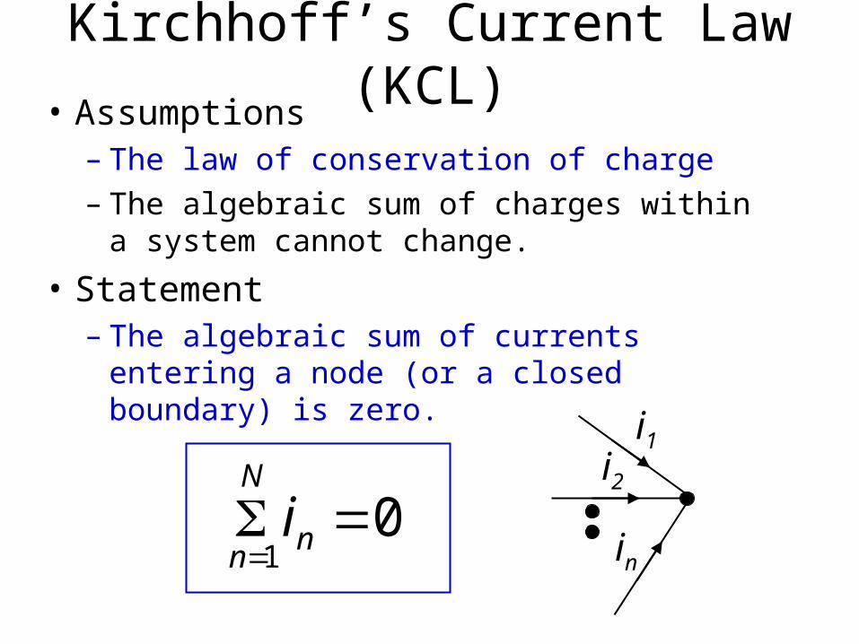
Kirchhoff’s Current Law (KCL)
i1
i2
in
01
n
N
ni
• Assumptions– The law of conservation of charge– The algebraic sum of charges within a system
cannot change.
• Statement– The algebraic sum of currents entering a node
(or a closed boundary) is zero.
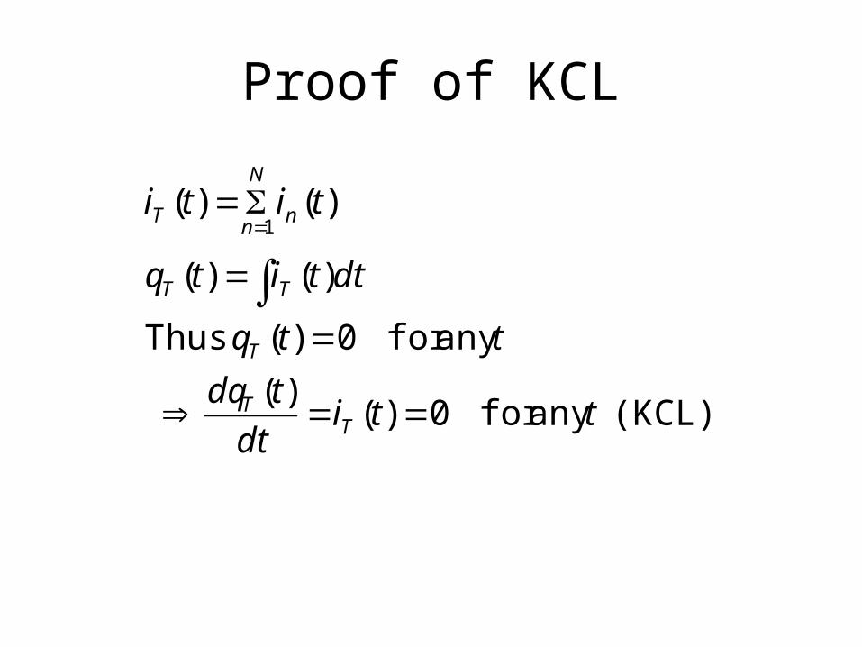
Proof of KCL
(KCL) any for 0)()(
any for 0)( Thus
)()(
)()(1
ttidt
tdq
ttq
dttitq
titi
TT
T
TT
n
N
nT
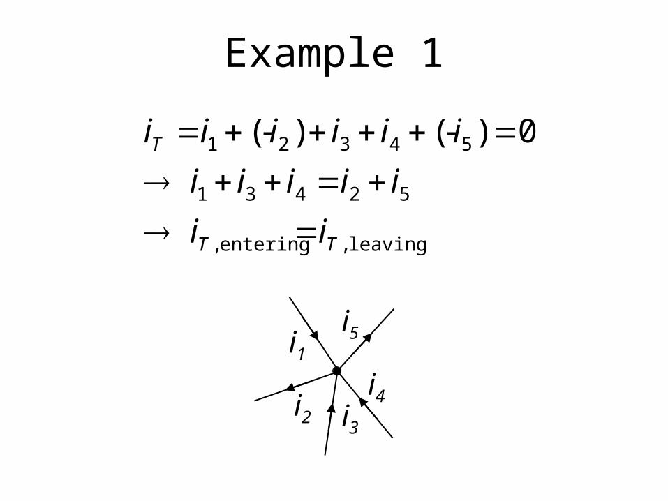
Example 1
i1
i3i2
i4
i5
leaving ,entering ,
52431
54321
0)-()-(
TT
T
ii
iiiii
iiiiii
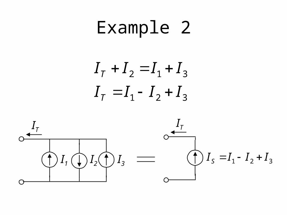
Example 2
321
312
IIII
IIII
T
T
I1 I2 I3
ITIT
321 IIIIS
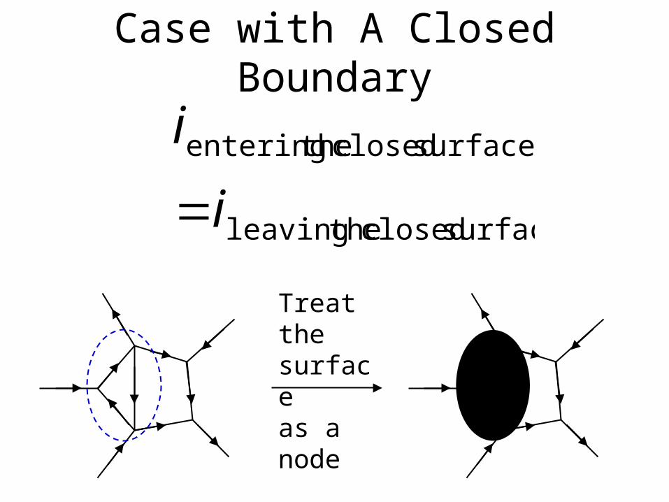
Case with A Closed Boundary
surface closed theleaving
surface closed theentering
i
i
Treat the surfaceas a node
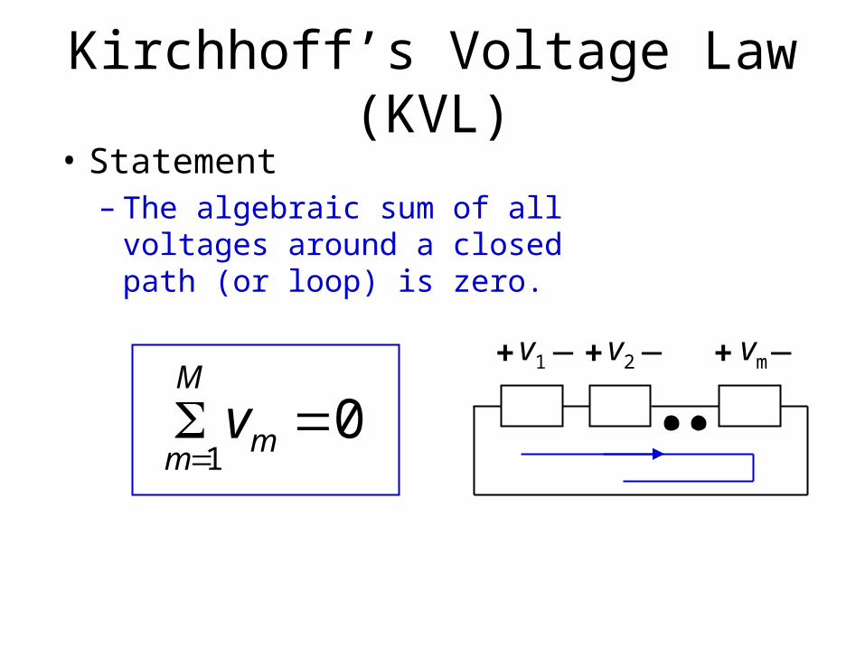
Kirchhoff’s Voltage Law (KVL)
01
m
M
mv
• Statement– The algebraic sum of all voltages
around a closed path (or loop) is zero.
v1+ _ v2+ _ vm+ _
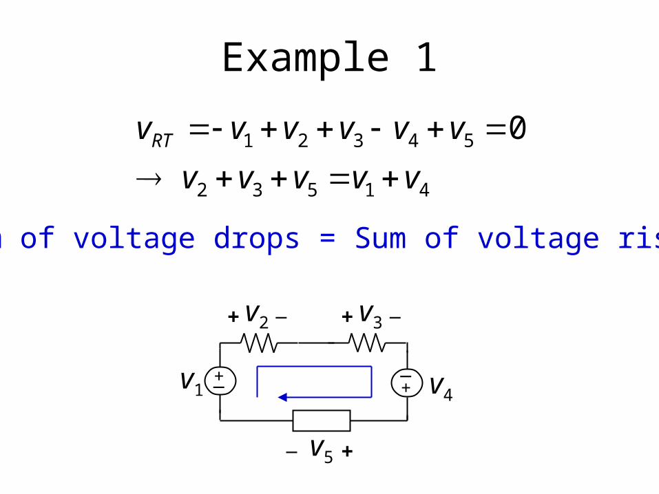
Example 1
41532
54321
0
vvvvv
vvvvvvRT
v4v1
v5
+_ +_
+_
v2+ _ v3+ _
Sum of voltage drops = Sum of voltage rises
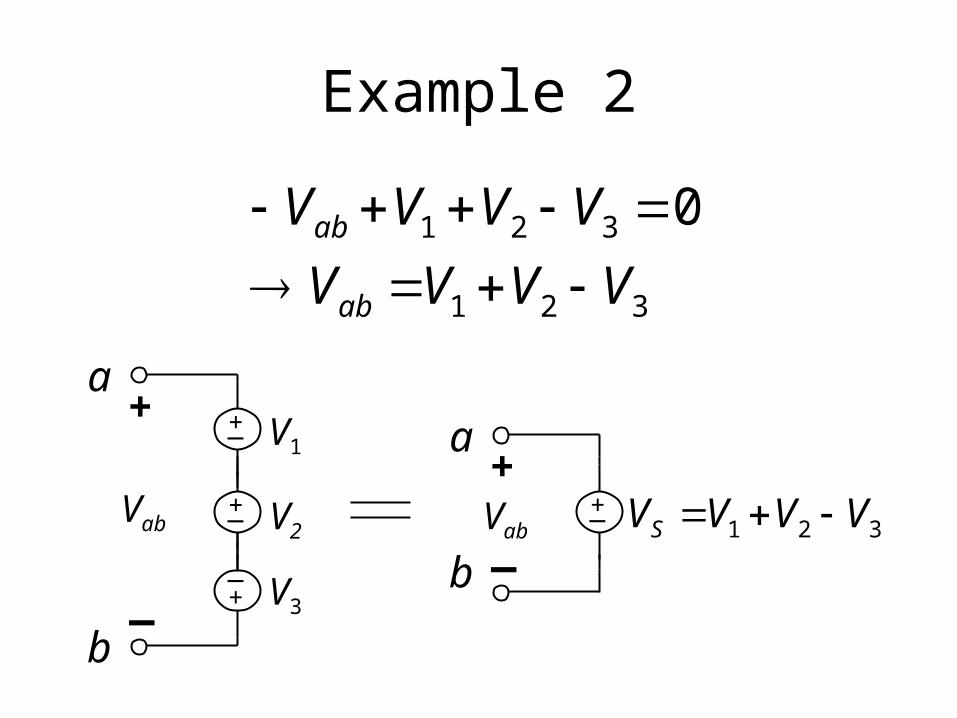
Example 2
321
321 0
VVVV
VVVV
ab
ab
V3
V2
V1
Vab
+_
+_
+_
+
_
a
b
Vab+_
+
_
a
b321 VVVVS
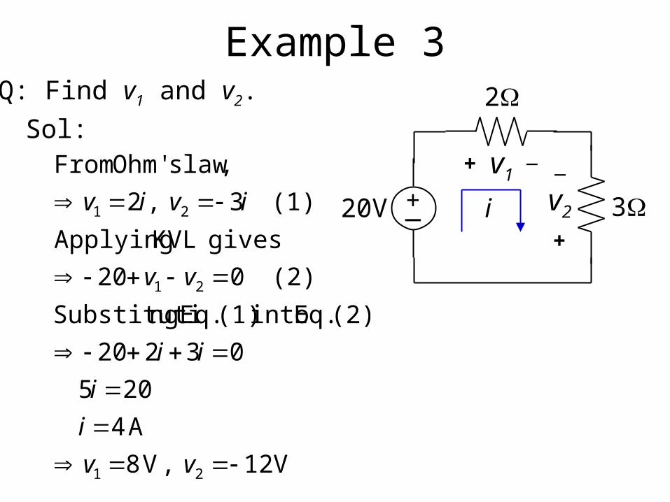
Example 3Q: Find v1 and v2.
Sol:
V 12 ,V 8
A 4
205
03220
(2), Eq. into (1) Eq. ngSubstituti
(2) 020
gives KVL Applying
(1) 3 ,2
,law sOhm' From
21
21
21
vv
i
i
ii
vv
iviv
v1+ _
v2
+
_
20V
2
3+_ i
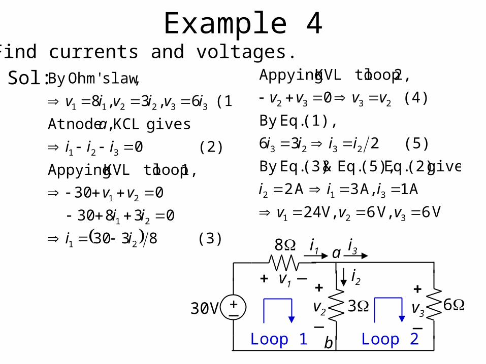
Example 4Q: Find currents and voltages.
Sol:
(3) 8330
03830
030
1, loop toKVL Appying
(2) 0
gives KCL , nodeAt
(1) 6 ,3 ,8
,law sOhm'By
21
21
21
321
332211
ii
ii
vv
iii
a
iviviv
V 6 V, 6 V, 24
A 1 A, 3A 2
gives (2) Eq. (5), Eq. & (3) Eq.By
(5) 236
(1), Eq.By
(4) 0
2, loop toKVL Appying
321
312
2323
2332
vvv
iii
iiii
vvvv
v1+ _
30V
8
3+_
i1
6+
_v3
i3
i2
Loop 1 Loop 2
a
+
_v2
b
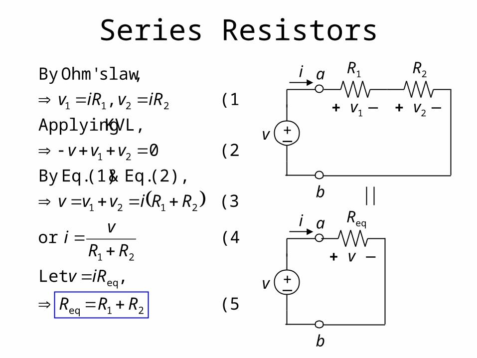
Series Resistors
(5)
, Let
(4) or
(3)
(2), Eq.&(1) Eq.By
(2) 0
KVL, Applying
(1) ,
,law sOhm'By
21eq
eq
21
2121
21
2211
RRR
iRv
RR
vi
RRivvv
vvv
iRviRv
v1+ _
v
R1
+_
i
v2+ _
R2a
b
v +_
i
v+ _
Reqa
b
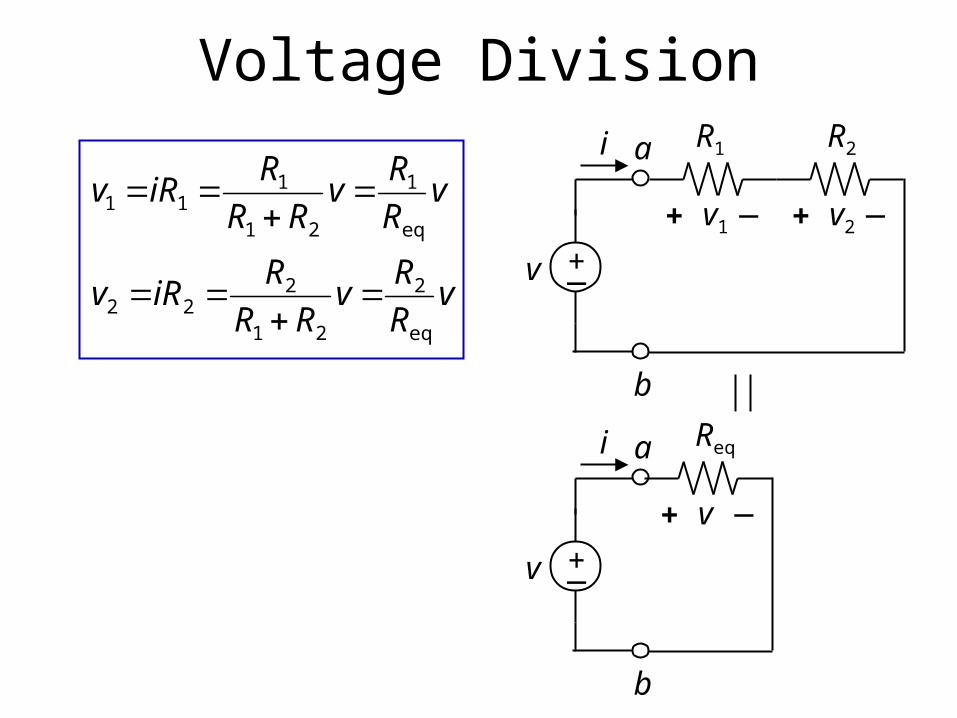
Voltage Division
vR
Rv
RR
RiRv
vR
Rv
RR
RiRv
eq
2
21
222
eq
1
21
111
v1+ _
v
R1
+_
i
v2+ _
R2a
b
v +_
i
v+ _
Reqa
b
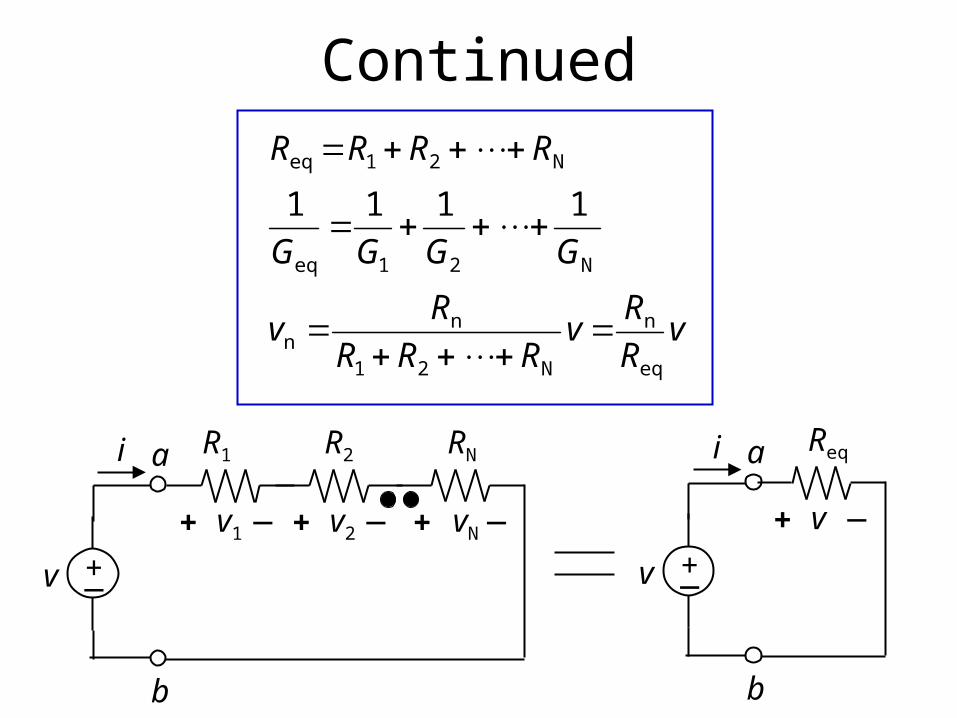
Continued
vR
Rv
RRR
Rv
GGGG
RRRR
eq
n
N21
nn
N21eq
N21eq
1111
v +_
i
v+ _
Reqa
b
v1+ _
v
R1
+_
i
v2+ _
R2a
b
vN+ _
RN
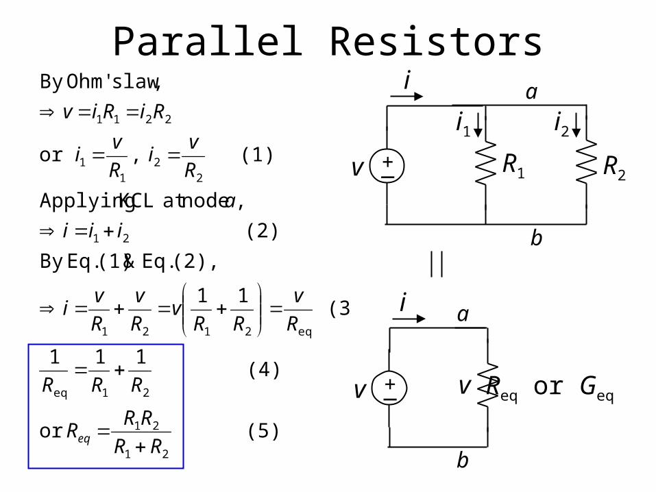
Parallel Resistors
(5) or
(4) 111
(3) 11
(2), Eq.&(1) Eq.By
(2)
, nodeat KCL Applying
(1) ,or
,law sOhm'By
21
21
21eq
eq2121
21
22
11
2211
RR
RRR
RRR
R
v
RRv
R
v
R
vi
iii
a
R
vi
R
vi
RiRiv
eq
i a
b
R1+_ R2v
i1 i2
i a
b
Req or Geq +_v v
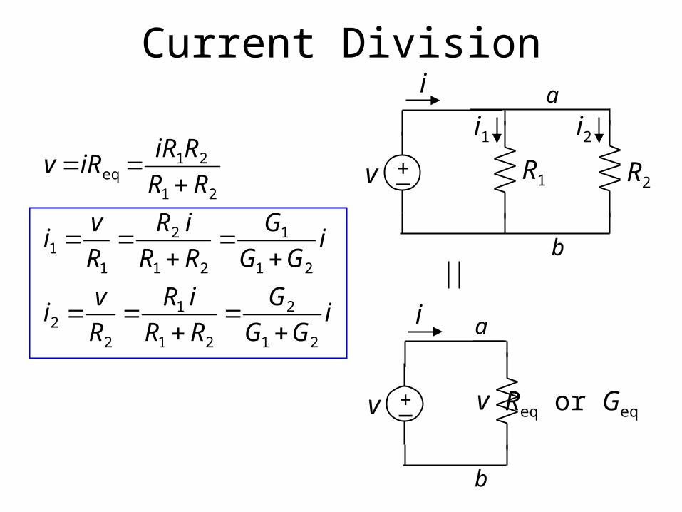
Current Division
iGG
G
RR
iR
R
vi
iGG
G
RR
iR
R
vi
RR
RiRiRv
21
2
21
1
22
21
1
21
2
11
21
21eq
i a
b
R1+_ R2v
i1 i2
i a
b
Req or Geq +_v v
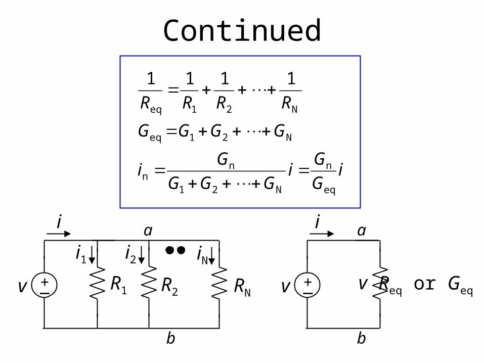
Continued
iG
Gi
GGG
Gi
GGGG
RRRR
eq
n
N21
nn
N21eq
N21eq
1111
i a
b
Req or Geq +_v v
i a
b
R1+_ R2v
i1 i2
RN
iN
iG
Gi
GGG
Gi
GGGG
RRRR
eq
n
N21
nn
N21eq
N21eq
1111
vR
Rv
RRR
Rv
GGGG
RRRR
eq
n
N21
nn
N21eq
N21eq
1111
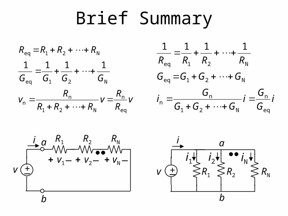
Brief Summary
i a
b
R1+_ R2v
i1 i2
RN
iNv1+ _v
R1
+_
i
v2+ _
R2a
b
vN+ _
RN
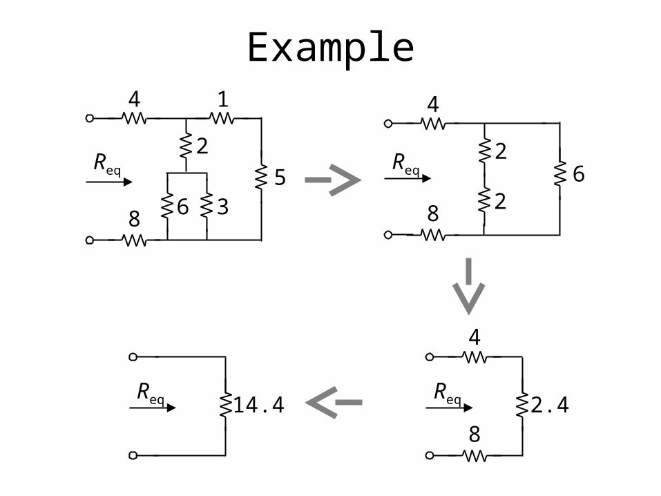
Example
Req
6 35
8
2
4 1
Req
26
8
2
4
Req 2.48
4
Req 14.4
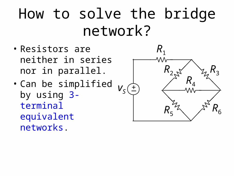
How to solve the bridge network?
R1
+_vS
R2 R3
R4
R5R6
• Resistors are neither in series nor in parallel.
• Can be simplified by using 3-terminal equivalent networks.
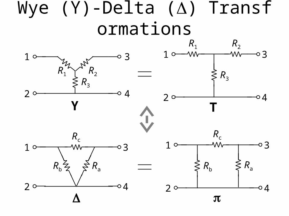
Wye (Y)-Delta () Transformations
R3
R1 R2
1
2
3
4
R3
R1 R2
3
4
1
2
Rb
Rc
1
2
3
4
RaRb
Rc
1
2
3
4
Ra
Y T
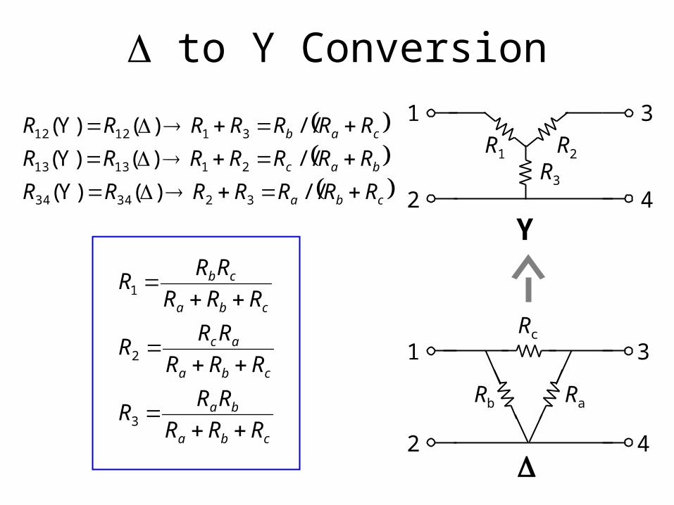
to Y Conversion
cba
bac
cab
RRRRRRR
RRRRRRR
RRRRRRR
//)()Y(
//)()Y(
//)()Y(
323434
211313
311212
cba
ba
cba
ac
cba
cb
RRR
RRR
RRR
RRR
RRR
RRR
3
2
1
R3
R1 R2
3
4
1
2
Y
Rb
Rc
1
2
3
4
Ra
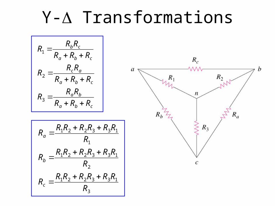
Y- Transformations
3
133221
2
133221
1
133221
R
RRRRRRR
R
RRRRRRR
R
RRRRRRR
c
b
a
cba
ba
cba
ac
cba
cb
RRR
RRR
RRR
RRR
RRR
RRR
3
2
1
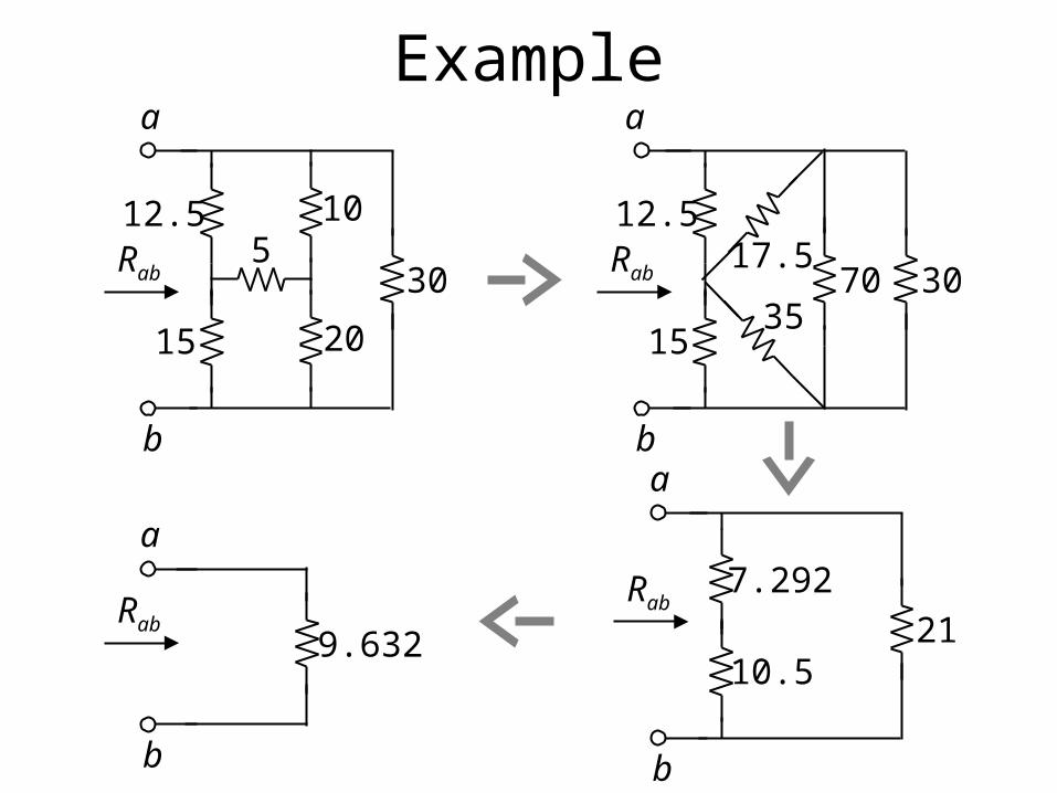
Example
Rab
12.5
15
510
30
20
a
b
Rab
12.5
15
17.570 30
a
b
35
Rab7.292
10.521
a
b
Rab9.632
a
b
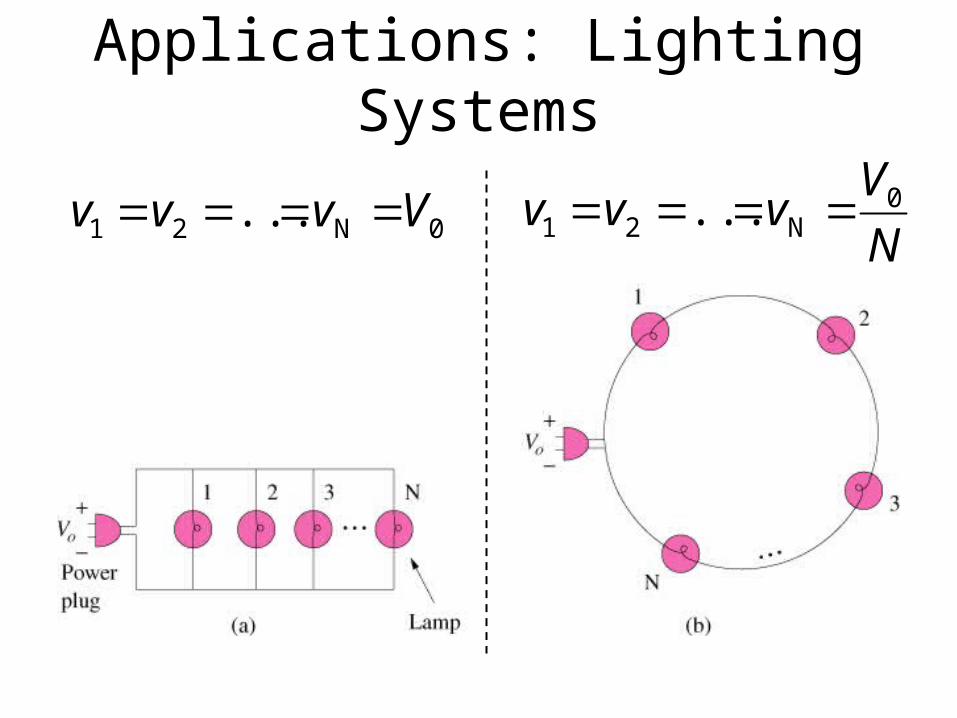
Applications: Lighting Systems
0N21 ... Vvvv N
Vvvv 0
N21 ...
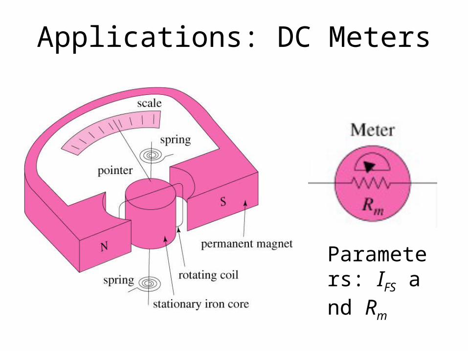
Applications: DC Meters
Parameters: IFS and Rm
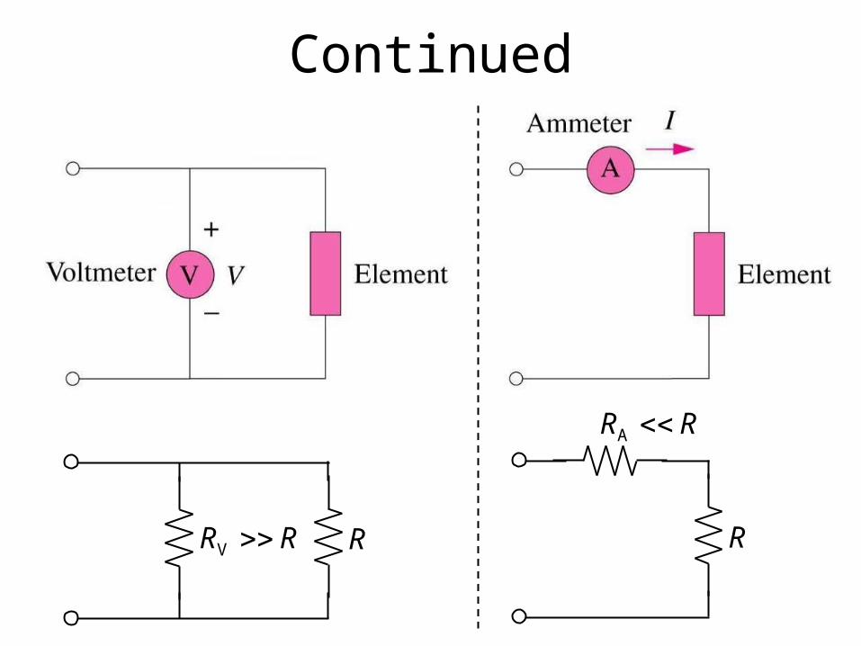
Continued
RR V R
RR A
R
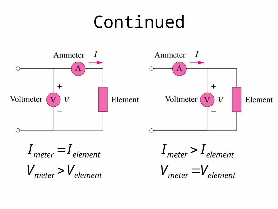
Continued
elementmeter
elementmeter
VV
II
elementmeter
elementmeter
VV
II
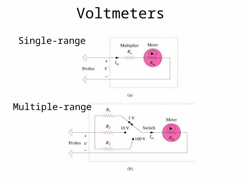
Voltmeters
Single-range
Multiple-range
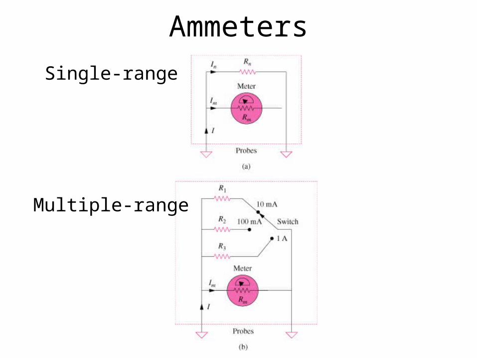
Ammeters
Single-range
Multiple-range