Embed Size (px)
Citation preview
The World Leader in High Performance Signal Processing Solutions
Basic Microcontroller
Integration Using Sigma Studio
Wilfrido Sierra
November 2010
Overview
This document will describe how to program a microcontroller to emulate SigmaStudio to communicate with a SigmaDSP IC in a real production system.
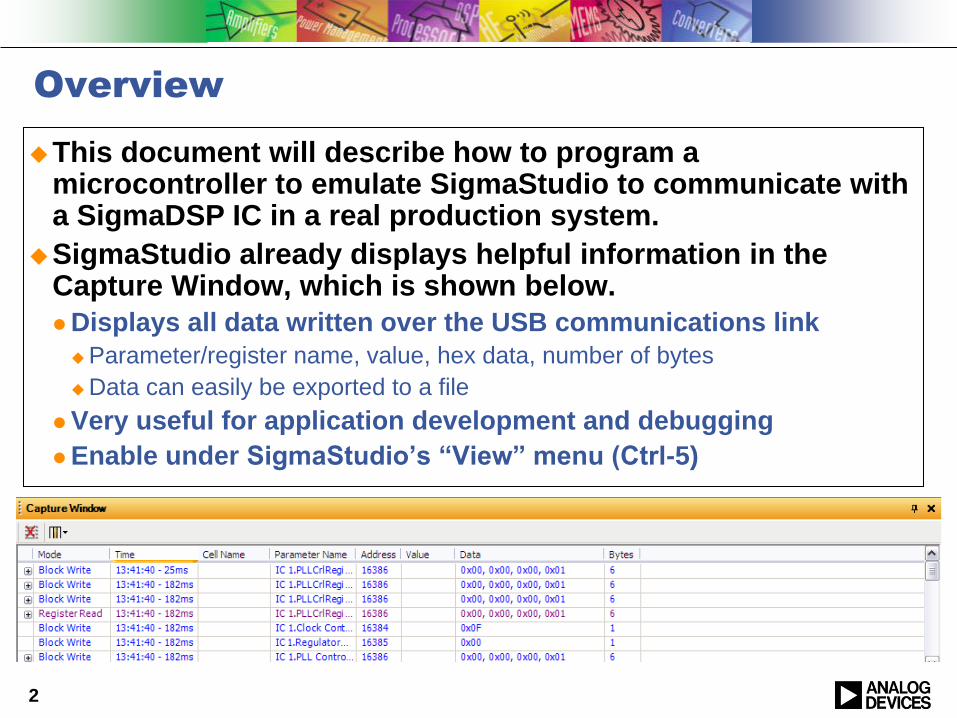
SigmaStudio already displays helpful information in the Capture Window, which is shown below.
Displays all data written over the USB communications link
Parameter/register name, value, hex data, number of bytes
Data can easily be exported to a file
Very useful for application development and debugging
Enable under SigmaStudio‟s “View” menu (Ctrl-5)
2
Sigma Studio Overview
3
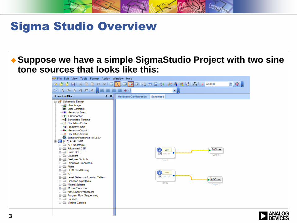
Suppose we have a simple SigmaStudio Project with two sine tone sources that looks like this:
Sigma Studio Overview (cont…)
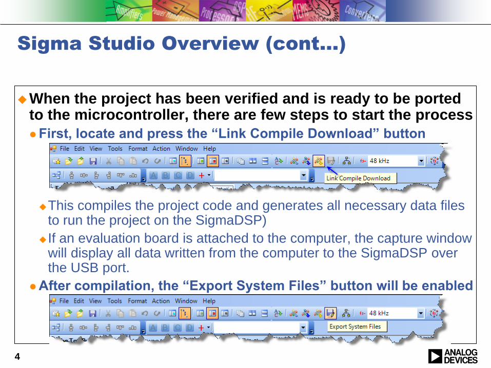
When the project has been verified and is ready to be ported to the microcontroller, there are few steps to start the process
First, locate and press the “Link Compile Download” button
This compiles the project code and generates all necessary data files to run the project on the SigmaDSP)
If an evaluation board is attached to the computer, the capture window will display all data written from the computer to the SigmaDSP over the USB port.
After compilation, the “Export System Files” button will be enabled
4
Sigma Studio Overview (cont…)
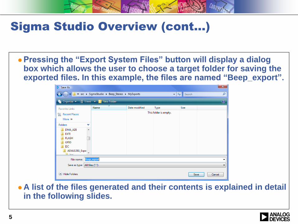
Pressing the “Export System Files” button will display a dialog box which allows the user to choose a target folder for saving the exported files. In this example, the files are named “Beep_export”.
A list of the files generated and their contents is explained in detail in the following slides.
5
Sigma Studio Overview (cont…)
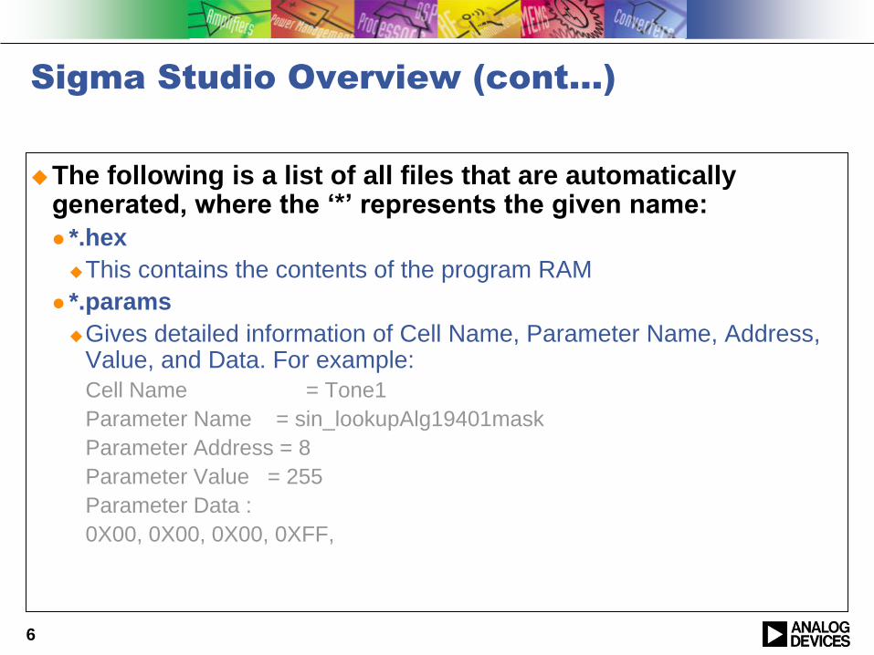
The following is a list of all files that are automatically generated, where the „*‟ represents the given name:
*.hex
This contains the contents of the program RAM
*.params
Gives detailed information of Cell Name, Parameter Name, Address, Value, and Data. For example:
Cell Name = Tone1
Parameter Name = sin_lookupAlg19401mask
Parameter Address = 8
Parameter Value = 255
Parameter Data :
0X00, 0X00, 0X00, 0XFF,
6
Sigma Studio Overview (cont…)
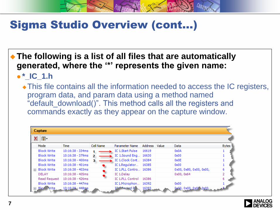
The following is a list of all files that are automatically generated, where the „*‟ represents the given name:
*_IC_1.h
This file contains all the information needed to access the IC registers, program data, and param data using a method named “default_download()”. This method calls all the registers and commands exactly as they appear on the capture window.
7
Sigma Studio Overview (cont…)
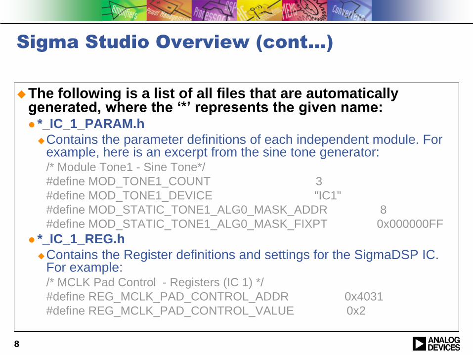
The following is a list of all files that are automatically generated, where the „*‟ represents the given name: *_IC_1_PARAM.h
Contains the parameter definitions of each independent module. For example, here is an excerpt from the sine tone generator:/* Module Tone1 - Sine Tone*/
#define MOD_TONE1_COUNT 3
#define MOD_TONE1_DEVICE "IC1"
#define MOD_STATIC_TONE1_ALG0_MASK_ADDR 8
#define MOD_STATIC_TONE1_ALG0_MASK_FIXPT 0x000000FF
*_IC_1_REG.h
Contains the Register definitions and settings for the SigmaDSP IC. For example:/* MCLK Pad Control - Registers (IC 1) */
#define REG_MCLK_PAD_CONTROL_ADDR 0x4031
#define REG_MCLK_PAD_CONTROL_VALUE 0x2
8
Sigma Studio Overview (cont…)
The following is a list of all files that are automatically generated, where the „*‟ represents the given name: defines.h
This is rather a legacy header file that defines the total number of transactions (i.e. writes to the I2C/SPI control port) already defined on our *_IC_1.h file. It also contains the total buffer size expressed in bytes. The “defines.h” is now seldom used, along with the “NumBytes_IC_1.dat” and “TxBuffer_IC_1.dat” files. Together, these three files duplicate the download sequence similar to default_download(). These files are still generated to maintain backwards-compatibility with older systems.
NumBytes_IC_1.dat
Contains an array, size of the total number of commands. Each element will let the microcontroller know how many bytes will be written in the transaction.
TxBuffer_IC_1.dat
Contains the actual data for the download transactions, which consists of address byte(s) followed by data.
9
Sigma Studio Overview (cont…)
SigmaStudioFW.h is the only file that is not automatically generated.
It is located in the base SigmaStudio installation folder (by default, this is [Program Files]\Analog Devices\Sigma Studio 3.x).
It contains a template with pre defined macros. The user has to implement these macros manually to be used with the desired microcontroller family.
One macro that is very helpful is the command “SIGMA_WRITE_REGISTER_BLOCK (int devAddress, int address, int length, ADI_REG_TYPE *pData ) ”, which contains basic information such as device address, instruction address and length, and instruction data.
10
Microcontroller Implementation
Now that the files have successfully been exported from SigmaStudio, microcontroller code can be developed.
This example uses the ARM Cortex M3 series and Keilintegrated development environment.
The user should define the basic microcontroller configuration such System Clocks, NVIC, GPIO, and the communication protocol configurations (in our case I2C) before continuing with this tutorial.
11
Microcontroller Implementation
First, open the “main.c” file.
In this file, the following header files must be included:
SigmaStudioFW.h (Assuming that the macros have been already defined by the user)
*_IC_1.h
*_IC_1_PARAM.h
12
Microcontroller implementation
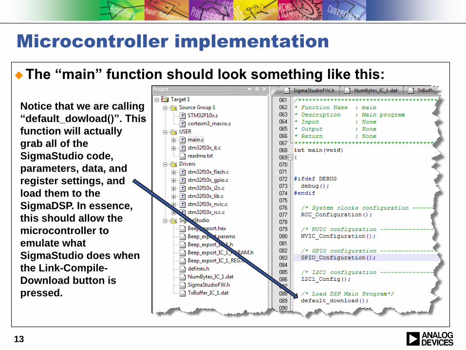
The “main” function should look something like this:
13
Notice that we are calling
“default_dowload()”. This
function will actually
grab all of the
SigmaStudio code,
parameters, data, and
register settings, and
load them to the
SigmaDSP. In essence,
this should allow the
microcontroller to
emulate what
SigmaStudio does when
the Link-Compile-
Download button is
pressed.
Microcontroller implementation (cont…)
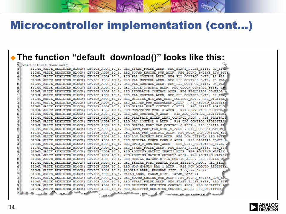
The function “default_download()” looks like this:
14
Microcontroller implementation (cont…)
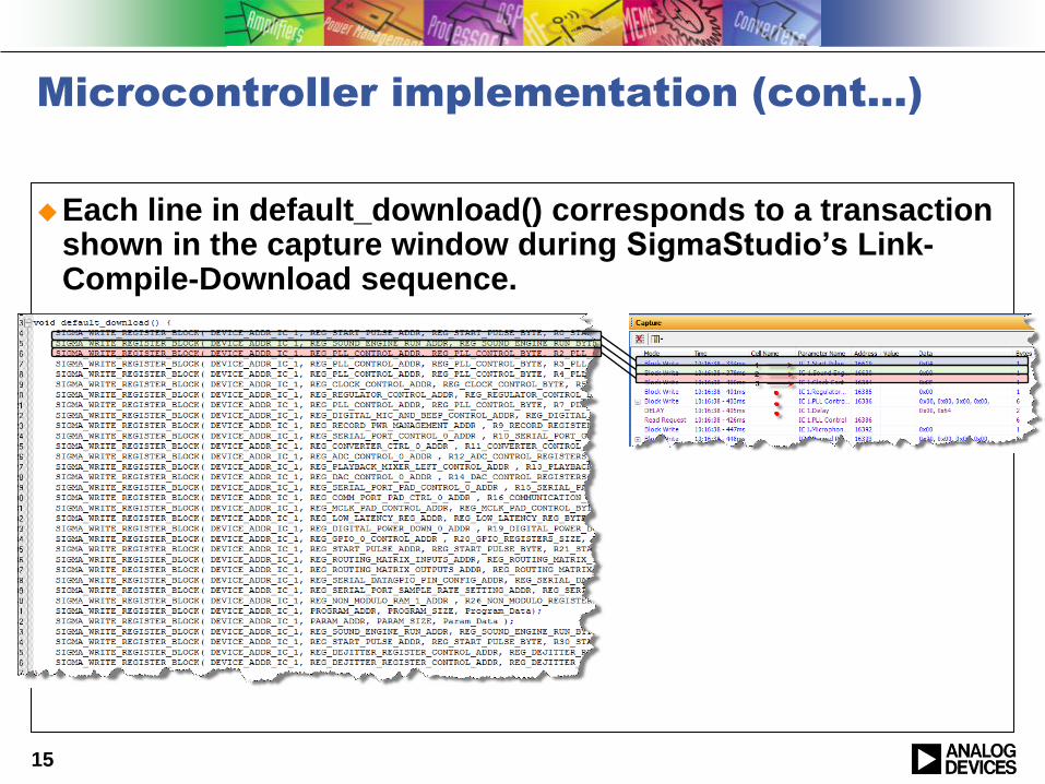
Each line in default_download() corresponds to a transaction shown in the capture window during SigmaStudio‟s Link-Compile-Download sequence.
15
Microcontroller implementation (cont…)
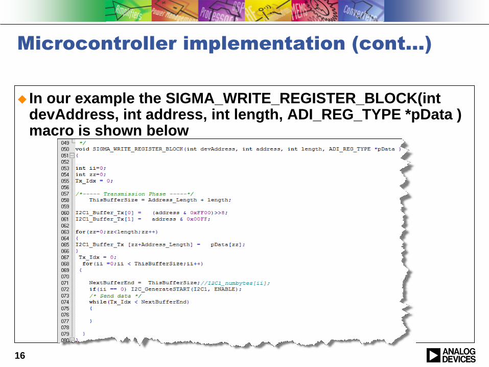
In our example the SIGMA_WRITE_REGISTER_BLOCK(intdevAddress, int address, int length, ADI_REG_TYPE *pData ) macro is shown below
16
Microcontroller implementation (cont…)
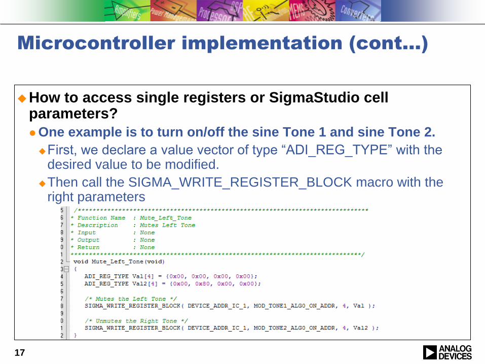
How to access single registers or SigmaStudio cell parameters?
One example is to turn on/off the sine Tone 1 and sine Tone 2.
First, we declare a value vector of type “ADI_REG_TYPE” with the desired value to be modified.
Then call the SIGMA_WRITE_REGISTER_BLOCK macro with the right parameters
17
Using the Sequencer Window
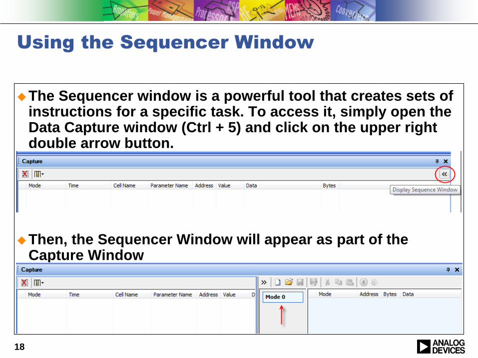
The Sequencer window is a powerful tool that creates sets of instructions for a specific task. To access it, simply open the Data Capture window (Ctrl + 5) and click on the upper right double arrow button.
Then, the Sequencer Window will appear as part of the Capture Window
18
Using the Sequencer Window (cont…)
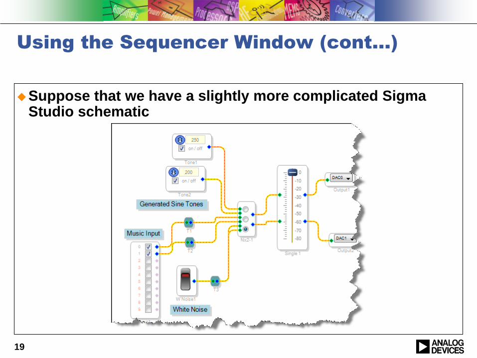
Suppose that we have a slightly more complicated Sigma Studio schematic
19
Using the Sequencer Window (cont…)
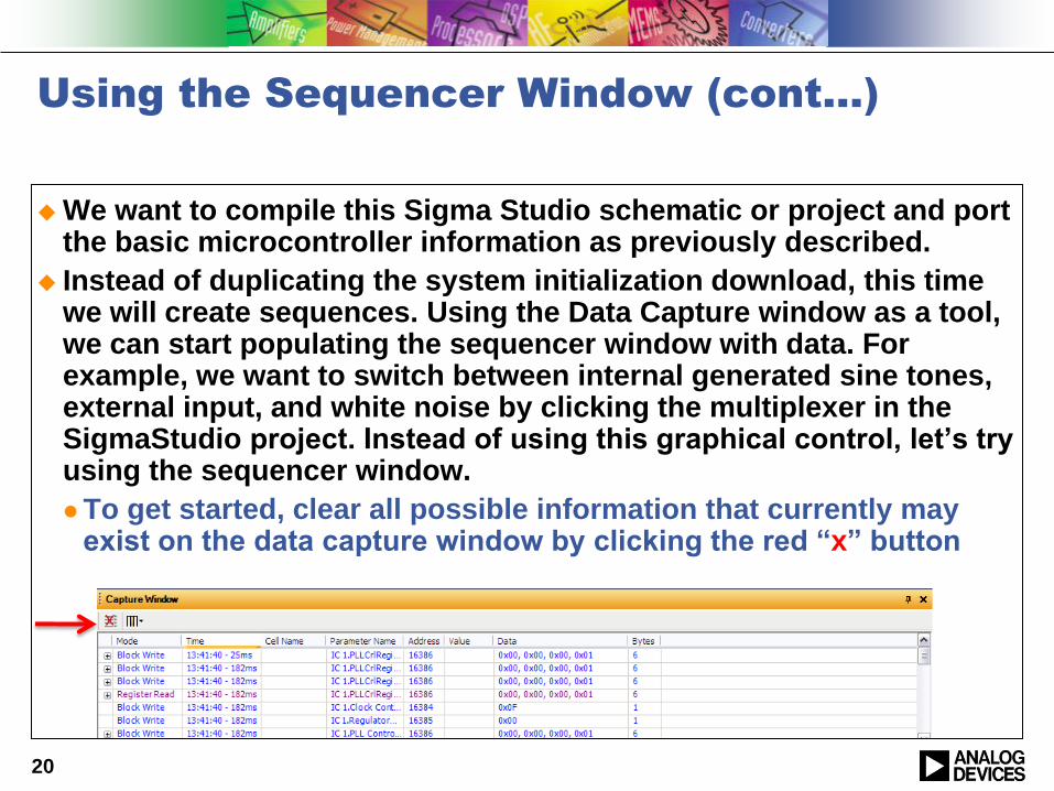
We want to compile this Sigma Studio schematic or project and port the basic microcontroller information as previously described.
Instead of duplicating the system initialization download, this time we will create sequences. Using the Data Capture window as a tool, we can start populating the sequencer window with data. For example, we want to switch between internal generated sine tones, external input, and white noise by clicking the multiplexer in the SigmaStudio project. Instead of using this graphical control, let‟s try using the sequencer window.
To get started, clear all possible information that currently may exist on the data capture window by clicking the red “x” button
20
Using the Sequencer Window (cont…)
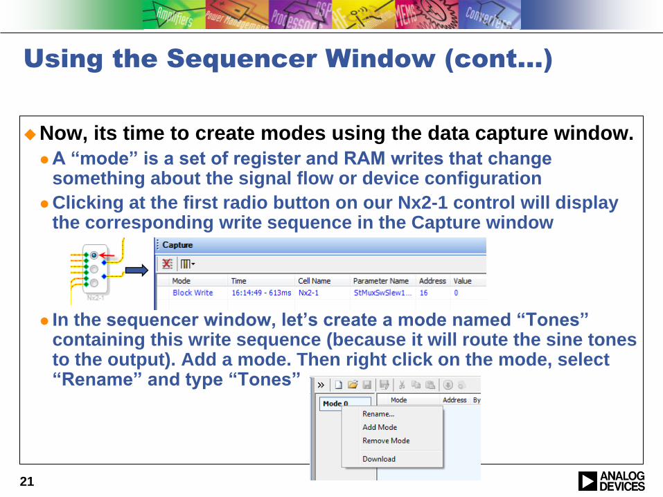
Now, its time to create modes using the data capture window.
A “mode” is a set of register and RAM writes that change something about the signal flow or device configuration
Clicking at the first radio button on our Nx2-1 control will display the corresponding write sequence in the Capture window
In the sequencer window, let‟s create a mode named “Tones” containing this write sequence (because it will route the sine tones to the output). Add a mode. Then right click on the mode, select “Rename” and type “Tones”
21
Using the Sequencer Window (cont…)
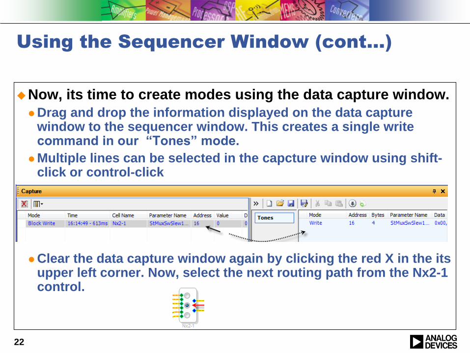
Now, its time to create modes using the data capture window.
Drag and drop the information displayed on the data capture window to the sequencer window. This creates a single write command in our “Tones” mode.
Multiple lines can be selected in the capcture window using shift-click or control-click
Clear the data capture window again by clicking the red X in the its upper left corner. Now, select the next routing path from the Nx2-1 control.
22
Using the Sequencer Window (cont…)
Now, its time to create modes using the data capture window.
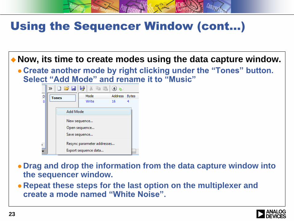
Create another mode by right clicking under the “Tones” button. Select “Add Mode” and rename it to “Music”
Drag and drop the information from the data capture window into the sequencer window.
Repeat these steps for the last option on the multiplexer and create a mode named “White Noise”.
23
Using the Sequencer Window (cont…)
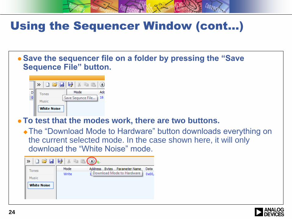
Save the sequencer file on a folder by pressing the “Save Sequence File” button.
To test that the modes work, there are two buttons.
The “Download Mode to Hardware” button downloads everything on the current selected mode. In the case shown here, it will only download the “White Noise” mode.
24
Using the Sequencer Window (cont…)
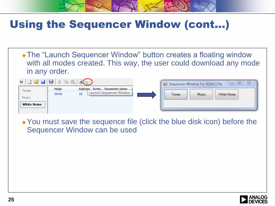
The “Launch Sequencer Window” button creates a floating window with all modes created. This way, the user could download any mode in any order.
You must save the sequence file (click the blue disk icon) before the Sequencer Window can be used
25
Exporting Sequences to a microcontroller
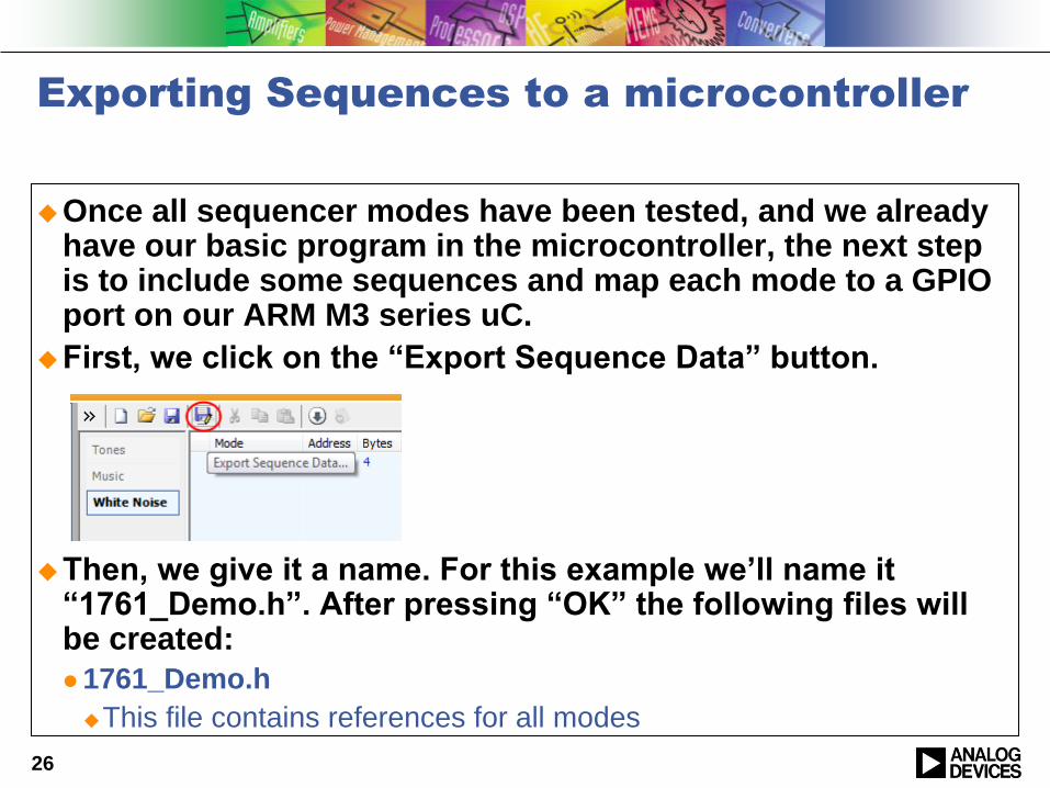
Once all sequencer modes have been tested, and we already have our basic program in the microcontroller, the next step is to include some sequences and map each mode to a GPIO port on our ARM M3 series uC.
First, we click on the “Export Sequence Data” button.
Then, we give it a name. For this example we‟ll name it “1761_Demo.h”. After pressing “OK” the following files will be created:
1761_Demo.h
This file contains references for all modes
26
Exporting Sequences to a microcontroller
(cont…)
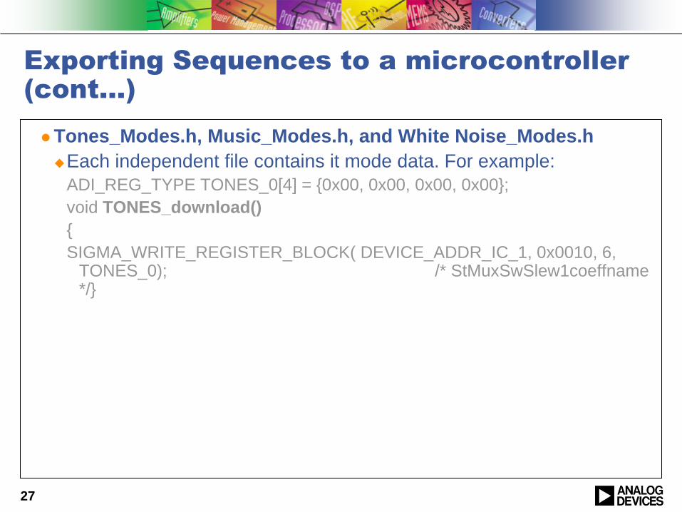
Tones_Modes.h, Music_Modes.h, and White Noise_Modes.h
Each independent file contains it mode data. For example:
ADI_REG_TYPE TONES_0[4] = {0x00, 0x00, 0x00, 0x00};
void TONES_download()
{
SIGMA_WRITE_REGISTER_BLOCK( DEVICE_ADDR_IC_1, 0x0010, 6, TONES_0); /* StMuxSwSlew1coeffname */}
27
Accessing Sequencer Modes
On the “main.c” file, we include the “1761_Demo.h” file.
We create another c file named “1761Demo_seq.c”.
Within this file we just simply call the function by its name. Using the example above, we just type in “TONES_download();” and that‟s all.
28
For reference
See the example files that were created for an ADAU1761 and an ARM Cortex M3
ADAU1761_Demo.zip
SigmaDSP Overview - October, 200929
Conclusion
Porting and using SigmaStudio header files for microcontrollers is as easy as pressing the “Export System Files” button.
The user needs to modify the SigmaStudioFW.h file to enable the pre configured macros within the microcontroller environment.
All SigmaDSP register and program information is automatically generated and ready to be used.
The Sequencer window is a powerful tool to access specific data within our SigmaDSP ICs.
30