Embed Size (px)
DESCRIPTION
portal design
Citation preview
Project No. FP6-004265
CoreGRID
European Research Network on Foundations, Software Infrastructures andApplications for large scale distributed, GRID and Peer-to-Peer Technologies
Network of Excellence
GRID-based Systems for solving complex problems
D.ETS.03 – Basic Portal’s Design Methodology and UserScenarios
Due date of deliverable: 31st August 2005Actual submission date: 14th October 2005
Start date of project: 1 September 2004 Duration: 48 months
Organisation name of lead contractor for this deliverable:Cardiff University
Revision: Final
Project co-funded by the European Commission within the Sixth Framework Programme(2002–2006)
Dissemination levelPU Public PU
Keyword list: Design methodologies, component model, tools/system compo-nents, Problem Solving Environments, portal components
CoreGRID FP6-004265 1
Contents
1 Introduction 2
2 User Scenario and Mapping Template 22.1 Grid-Awareness . . . . . . . . . . . . . . . . . . . . . . . . . . . . 32.2 User Interface . . . . . . . . . . . . . . . . . . . . . . . . . . . . . 32.3 Infrastructure Used . . . . . . . . . . . . . . . . . . . . . . . . . . 32.4 Middleware Used . . . . . . . . . . . . . . . . . . . . . . . . . . . 32.5 Service Representation . . . . . . . . . . . . . . . . . . . . . . . . 32.6 Workflow Requirements . . . . . . . . . . . . . . . . . . . . . . . 42.7 Runtime Requirements . . . . . . . . . . . . . . . . . . . . . . . . 4
3 User Scenarios 43.1 Bioinformatics applications using BLAST(INRIA) . . . . . . . . 43.2 Weather Forecast Application (UoW, SZTAKI) . . . . . . . . . . 53.3 Urban Traffic Simulation. (UoW, SZTAKI) . . . . . . . . . . . . 73.4 Grid-based e-Marketplace. (UoW, SZTAKI) . . . . . . . . . . . . 93.5 Library Level Legacy Code Wrapping. (UWC, FORTH-ICS) . . 103.6 Dynamic Data Driven Application Scenario for Pipeline Model-
ing. (UWC) . . . . . . . . . . . . . . . . . . . . . . . . . . . . . . 123.7 Molecular Dynamics Simulation. (HLRS) . . . . . . . . . . . . . 133.8 GRID superscalar applications using BLAST. (UPC) . . . . . . . 153.9 Chemical application - using GAMESS. (UPC) . . . . . . . . . . 163.10 Performance Analysis Scenario. (UPC) . . . . . . . . . . . . . . . 183.11 Hospital Information System. (UoW) . . . . . . . . . . . . . . . . 183.12 Legacy Systems as Grid Services. (CYFRONET) . . . . . . . . . 21
4 From User Requirement to Portal Design 224.1 Workflow Execution and Representation . . . . . . . . . . . . . . 234.2 Cross VO integration . . . . . . . . . . . . . . . . . . . . . . . . . 234.3 Middleware Flexibility/Choice - Insulation from Middleware . . . 234.4 Dynamic Steering . . . . . . . . . . . . . . . . . . . . . . . . . . . 244.5 Dynamic Deployment . . . . . . . . . . . . . . . . . . . . . . . . 244.6 Portal Design . . . . . . . . . . . . . . . . . . . . . . . . . . . . . 24
5 Conclusion 26
CoreGRID - Network of Excellence
CoreGRID FP6-004265 2
1 Introduction
An effective portal interface is more than just following a set of rules. It requiresa user-centered attitude and design methodology. It also requires early planningof the interface and continued work throughout the development process. Inthis document therefore, we present the design methodology for a portal byexamining the requirements from a collection of user scenarios, which have beenprepared according to a specific template that was designed to facilitate themapping between the application primitives and the underlying Grid tools andservices. In the following section, we describe the mapping template that shapedthe user scenarios. The scenarios themselves are given in Section 3. We thenpresent how these can be mapped into the specification for the Portal design inSection 4.
2 User Scenario and Mapping Template
In the Work package 7 Barcelona meeting, we discussed in detail a number ofapplication or user scenarios that the various partners could provide. From thesediscussions, we extracted a template, which could be used to serve as a guidelinefor points that needed to be addressed when constructing such scenarios. Wewere careful to pay particular attention so that the scenario authors consideredthe mapping from their scenarios to the available tools and middleware. Thistemplate is used as a basis therefore to be able to extract the commonalitiesin usage patterns and therefore forms the preliminary taxonomy for the designmethodology for next-generation portals. This format consisted of two mainsections, with points for authors to address within each section, as follows:
1. Scientific User Scenario: Here, the scenario is given from the scientist’sperspective. The scenario author should set out the problem paying par-ticular attention to which distributed aspects they require for execution.the author should also specify the Quality of Service (QoS) requirementsthat are expected to be gained from such a mapping across the distributedresources.
2. Mapping to the underlying infrastructure: Here, the technical mappingfrom the given user scenario to the underlying infrastructure should begiven, paying particular attention to describing the following aspects:
• Is the application Grid aware or unaware?
• User Interface
• Identify type of infrastructure used (e.g. Grid or P2P)
• Technologies used e.g. GT, GAT, Unicore etc
• Service representation.
• Workflow requirements (representation)
• What kind of monitoring/steering id required?
CoreGRID - Network of Excellence
CoreGRID FP6-004265 3
Each of these categories are expanded upon, in the following subsections.
2.1 Grid-Awareness
A major issue is whether the application the user wishes to run is Grid awareor not. From the users perspective, most would argue, this difference shouldbe transparent. In some cases legacy applications need to to gridified withoutchanging the behaviour from the users point of view. In other cases they mayneed to be wrapped entirely, for example as a Web services.
2.2 User Interface
As Grid scenarios become more sophisticated, so the user interfaces must keeppace. These need to cope with various underlying resource/service/workflowdescription technologies, many of which are still evolving, in order to rendergrid entities. Interfaces need to be flexible but also intuitive and simple in orderto handle different user types (for example grid aware users may wish to definethings such as resources to use while others may not). The design of resourcedescription mechanisms therefore needs to take these issues into consideration.
2.3 Infrastructure Used
Users may expect differing grid infrastructures depending on the scenario. Forexample certain applications may require highly dynamic and distributed dis-covery environments. Others may require server-centric data repositories. Theability to behave flexibly according to users needs in this regard is an importantaspect of developing a scalable, generic grid environment.
2.4 Middleware Used
Many existing applications already rely on a middleware layer that may begrid enabled in some way. Users and developers will be reluctant to dismantleexisting capabilties in order to experiement with new technologies. It is impor-tant therefore to be able to integrate these into an inclusive grid environment,enabling diverse views of a grid to co-exist.
2.5 Service Representation
With new Grid technologies moving towards the service oriented paradigm,shared views of service representation need to be developed. Furthermore, whilethere are existing standards of service representation and communication witha broad base of acceptance (WSDL and SOAP for example), this area is still inan evolutionary phase. Emerging technologies which are either richer or moreefficient need to be able to be integrated when they achieve maturity.
CoreGRID - Network of Excellence
CoreGRID FP6-004265 4
2.6 Workflow Requirements
Workflow is becoming more and more important in Grid user scenarios, in partdue to the adoption of SOA which views the network as discreet entities pro-viding well defined services. Understanding the workflow requirements of usersscenarios will help in defining generic mechanisms for describing and implement-ing them.
2.7 Runtime Requirements
The ability to monitor/steer/migrate running applications is paramount in op-timising not only application performance, but user performance as well. Theserequirements become more complex to implement as the underlying distributedtopology becomes more complex and more dynamic. For example new work-flows may be programatically spawned as a result of previous output, or userpreference, and these workflows may themselves be constructed from diverse re-sources and systems. The interface to this runtime environment must be capableof handling this kind of dynamic activity.
3 User Scenarios
In this section the scenarios received from institutions and projects are listedand, where appropriate, how they relate to the underlying infrastructure.
3.1 Bioinformatics applications using BLAST(INRIA)
Projects: ProActive [21], OASIS [18]
BLAST (Basic Local Alignment Search Tool) [1] is by far the most widelyused algorithm for rapid sequence comparison. However, sequence databasesare growing at an exponential rate - currently doubling in about 14 months -exceeding Moore’s Law for hardware acceleration which is about 18 months.Consequently, sequence comparison against these ever-growing databases is in-creasingly becoming computationally challenging. To meet these demands, highperformance parallel computing methodologies should be applied. However, sin-gle query or batch query mode is still used primarily.
There are several freely available softwares which allow users to search thesimilarity of one biological sequence against others by employing the BLASTalgorithm. However, one particular implementation of BLAST developed byNCBI (National Center for Biotechnology Information) [17] stands out of thecrowd and remains as an ad-hoc standard till date.
We developed GeB, a GRID-enabled parallel version of NCBI BLAST basedon ProActive. The implementation is based on ProActive Group Communica-tion, and uses the standard, unmodified, NCBI software. So the scientist justhas to use the normal software, and moreover, when a new version of NCBIBLAST is developed, he or she can just use the new one with ProActive and
CoreGRID - Network of Excellence
CoreGRID FP6-004265 5
the Grid to benefit from the new algorithmic advances.
Mapping to the underlying infrastructure
1. Grid aware or unaware application - Grid unaware
2. Type of infrastructure used - ProActive environment. We chose the tradi-tional master-slave approach for GeB where the master does most of thenon-calculative jobs (like sending the queries to different nodes, mergingand building of final results etc.) while the slave nodes do the calculationsand return results back to the master.
3. Technologies used - The Java code being developed takes advantage of theProActive deployment infrastructure. Using the notion of Virtual Node,and the capacity to deploy on many protocols and platforms (ssh, rsh,RMI/ssh Tunneling, Globus [8] GT2, GT3, and GT4, sshGSI, LSF, PBS,Sun Grid Engine [25], Unicore [28], EGEE gLite [4], etc.), we can deployin cluster, Grid, P2P environments.
3.2 Weather Forecast Application (UoW, SZTAKI)
Projects: GEMLCA [7], P-Grade Portal [20]
The main objective of a meteorological nowcasting system is to analyse andpredict in the ultra short range (up to 6 hours) those weather phenomena, whichmight be dangerous for life and property. Typically such events are snow storms,freezing rain, fog, convective storms, etc. The MEsoscale Analysis Nowcastingand DEcision Routines, (MEANDER), developed by the Hungarian Meteoro-logical Service, are the core software components of a nowcasting system.
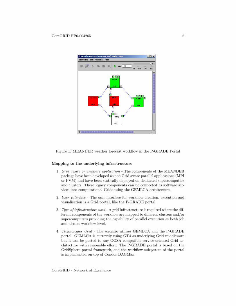
The MEANDER package consists of five different algorithms. Each calcula-tion algorithm is computation intensive and implemented as a parallel programcontaining C/C++ and FORTRAN sequential code. The programs are depend-ing on each other, thus the whole MEANDER simulation can be represented bya workflow as it can be seen in Figure 1. An important constraint for the simu-lation is that the analysis and the 6 hour forecasting should be available within20 minutes after the measurement time. In order to meet this strict requirementthe parallel components must be executed on dedicated, high-availability clus-ters orchestrated by an automated workflow engine that is capable to performthe execution and the data transfer processes automatically.
The advantage of the workflow approach is that it introduces parallelismat two levels. The top level parallelism comes from the workflow concept, i.e.,independent branches of a workflow can be executed simultaneously on differentclusters. The bottom level parallelism is the consequence of the fact that thenodes of the workflow are themselves parallel programs.
CoreGRID - Network of Excellence
CoreGRID FP6-004265 6
Figure 1: MEANDER weather forecast workflow in the P-GRADE Portal
Mapping to the underlying infrastructure
1. Grid aware or unaware application - The components of the MEANDERpackage have been developed as non Grid aware parallel applications (MPIor PVM) and have been statically deployed on dedicated supercomputersand clusters. These legacy components can be connected as software ser-vices into computational Grids using the GEMLCA architecture.
2. User Interface - The user interface for workflow creation, execution andvisualisation is a Grid portal, like the P-GRADE portal.
3. Type of infrastructure used - A grid infrastructure is required where the dif-ferent components of the workflow are mapped to different clusters and/orsupercomputers providing the capability of parallel execution at both joband also at workflow level.
4. Technologies Used - The scenario utilises GEMLCA and the P-GRADEportal. GEMLCA is currently using GT4 as underlying Grid middlewarebut it can be ported to any OGSA compatible service-oriented Grid ar-chitecture with reasonable effort. The P-GRADE portal is based on theGridSphere portal framework, and the workflow subsystem of the portalis implemented on top of Condor DAGMan.
CoreGRID - Network of Excellence
CoreGRID FP6-004265 7
5. Service Representation - GEMLCA presents each parallel program as aGrid/Web service (a GT4 service in the current implementation) that canbe accessed through a standard WSDL interface.
6. Workflow requirements (representation) - Once the programs of the ME-ANDER package are made accessible as Grid services, the different compo-nents can be connected into a workflow by using an appropriate developertool, such as the P GRADE Portal. Although the workflow developmentprocess requires significantly less effort than the development of the indi-vidual parallel components did, it still assumes some basic programmingknowledge. However, once the workflow definition is uploaded to the P-GRADE Portal server, the simulation can be started and controlled bythe real users (i.e. the meteorologists) who know where the up to dateenvironmental data (collected by radars, satellites and balloons) can befound.
7. Runtime requirements - The whole workflow execution can be monitoredthrough the graphical GUI of the P GRADE Portal. After the simulationterminated the results can be downloaded onto the desktop computer andcan be browsed by special editors or visualization tools.
3.3 Urban Traffic Simulation. (UoW, SZTAKI)
Projects: GEMLCA [7], P-Grade [20]
A traffic simulation application is typically built from different functionalbuilding blocks. For example one module generates a road network file that de-scribes the topology of a road network and the allowed junction manoeuvres onthe roads. A second component, the actual simulator, simulates car movementsin time using the previous network file as input. The results of the simulation,typically a trace file, can be loaded into different visualiser and analyser tools.In a realistic scenario traffic analysts wish to run several simulations to anal-yse the effects of changing network parameters, like traffic light patterns, oneway streets or the effects of increased traffic on particular roads. They createa workflow where the results of the road network generator are fed into sev-eral simulator components, and then the outputs are sent to analyser/visualisercomponents. This requires parameter study like execution of several simulationsand their subsequent analysis. Distribution appears at two different levels. Thecomponents of the workflow could be either sequential or parallel applicationsthat require a computer cluster. Also, some components of the workflow can beexecuted parallel to each other on different Grid resources. The added value forthe end-user of making the legacy applications Grid enabled:
• Workflow can be easily created where the execution of the different com-ponents is synchronised according to the workflow execution graph, andthe input/output files are automatically transferred between the differentsites.
CoreGRID - Network of Excellence
CoreGRID FP6-004265 8
• Different instances of the same application can run on remote clus-ters/supercomputers at the same time with different input parametersspeeding up parameter studies.
• The traffic analyst can utilise simulators running on remote resources. Asimple laptop/desktop is enough to run the simulation and retrieve results.
• Using a collaborative portal solution allows different traffic analysts ondifferent locations to create workflows together each adding the componentand resource she is authorised to use.
Mapping to the underlying infrastructure
1. Grid aware or unaware application - The components of the above de-scribed workflow were typically written as non Grid aware applicationsand are usually massive MPI or PVM parallel codes that run on super-computers or clusters. The installation process of these applications canbe rather demanding and they use proprietary interfaces for communi-cation. These legacy components of the workflow have to be deployedon several Grid sites and exposed as Grid services using GEMLCA. Thesource codes of these legacy applications are typically not available (espe-cially if we are talking about commercial products) resulting in a need forcoarse grained black-box type wrapping.
2. User Interface - The user interface for workflow creation, execution andvisualisation is a Grid portal, like the P-GRADE portal.
3. Type of infrastructure used - A grid infrastructure is required where the dif-ferent components of the workflow are mapped to different clusters and/orsupercomputers providing the capability of parallel execution at both joband also at workflow level.
4. Technologies Used - The scenario utilises GEMLCA and the P-GRADEportal. GEMLCA is currently using GT4 as underlying Grid middlewarebut it can be ported to any OGSA compatible service-oriented Grid ar-chitecture with reasonable effort. The P-GRADE portal is based on theGridSphere portal framework, and the workflow subsystem of the portalis implemented on top of Condor DAGMan.
5. Service Representation - The legacy applications are represented as Grid/Webservices according to the service representation offered by the underlyingGrid infrastructure (e.g. GT4 services in the current implementation).
6. Workflow requirements (representation) - Once the components are ex-pressed as Grid services workflow can be created using the workflow en-gine of the P-GRADE portal, for example. The different components ofthe workflow can be mapped either statically (in the current solution) atworkflow creation time, or dynamically (once GEMLCA is extended witha broker and automatic service deployment) at run-time to the available
CoreGRID - Network of Excellence
CoreGRID FP6-004265 9
resources. The communication between workflow components is scheduledby Condor DAGMan and executed as file transfers between the sites.
7. Runtime requirements - The success or failure of a particular job haveto be monitored. If the execution of a job failed the user can map theexecution into another resource (in the current solution), or the job isautomatically migrated into another site (once the system is extendedwith an appropriate broker).
3.4 Grid-based e-Marketplace. (UoW, SZTAKI)
Projects: GEMLCA [7]
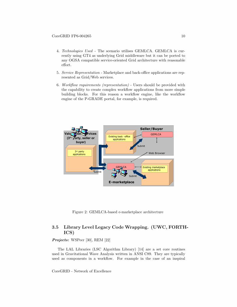
An e-marketplace is an internet site where potential business partners cancome together in order to exchange goods and services. Although offering sub-stantial business advantages such as reduced transaction costs, integrated pro-cesses in supply chains, shortened purchase cycles, greater transparency andlower administrative costs, e-marketplaces are still facing significant technicaldifficulties. Integrating legacy back-office applications and ERP (Enterprise Re-source Planning) systems with marketplaces is a complex, and expensive task,but one which is necessary in order to utilise fully the opportunities of exchangesites. Today, e-marketplaces offer only limited functionality due to the diffi-culties in integrating existing value-added services. These services often alsorequire large computational power such as logistics optimisation algorithms. Inthis scenario back-office, marketplace and third party applications are all pre-sented as Grid services allowing the seamless integration of these applicationsindependently of the hardware and software platforms they are running on. Thisprovides marketplace operators to more easily integrate already existing valueadded services to the marketplace, and marketplace participants to more easilyconnect their back-office applications to marketplace services.
Mapping to the underlying infrastructure
1. Grid aware or unaware application - Both Marketplace and back-officeapplications are typically legacy components that are not Grid aware.The source codes of these legacy applications are typically not available(especially if we are talking about commercial products) resulting in aneed for coarse grained black-box type wrapping provided by GEMLCA.However, the integration with specifically written Grid aware applicationsis also a requirement.
2. User Interface - The user interface is an e-marketplace portal that can beextended with Grid specific functionalities and a workflow engine.
3. Type of infrastructure used - A grid infrastructure is required where the dif-ferent components of the workflow are mapped to different clusters and/orsupercomputers providing the capability of parallel execution at both joband also at workflow level.
CoreGRID - Network of Excellence
CoreGRID FP6-004265 10
4. Technologies Used - The scenario utilises GEMLCA. GEMLCA is cur-rently using GT4 as underlying Grid middleware but it can be ported toany OGSA compatible service-oriented Grid architecture with reasonableeffort.
5. Service Representation - Marketplace and back-office applications are rep-resented as Grid/Web services.
6. Workflow requirements (representation) - Users should be provided withthe capability to create complex workflow applications from more simplebuilding blocks. For this reason a workflow engine, like the workflowengine of the P-GRADE portal, for example, is required.
GEMLCAGEMLCA
Seller/Buyer
E-marketplace
Value added services
(3rd party, seller or
buyer)
Existing back -office
applications
GEMLCA Existing marketplace applications
3rd party
applications
Submit
Web Browser
Submit
Submit
Figure 2: GEMLCA-based e-marketplace architecture
3.5 Library Level Legacy Code Wrapping. (UWC, FORTH-ICS)
Projects: WSPeer [30], REM [22]
The LAL Libraries (LSC Algorithm Library) [14] are a set core routinesused in Gravitational Wave Analysis written in ANSI C89. They are typicallyused as components in a workflow. For example in the case of an inspiral
CoreGRID - Network of Excellence
CoreGRID FP6-004265 11
search (searching an inspiralling compact binary system consisting of a pair ofdense, compact objects - either neutron stars or black holes - orbiting aroundeach other) a bank of ‘templates’ which represent theoretically possible patternspresent in the raw detector data, is initally calculated. Typically there may beseveral thousands of templates in a bank, and the data stretch may be severalyears long, sampled at 16KHz. These templates are then searched for in theraw data using a correlation. This correlation algorithm runs for each templatein the bank and can be run in parallel. Furthermore the correlation itself mayalso be able to be broken into workflow components and likewise run in parallel.The outputs from the correlations are stored for subsequent analysis.
A physicist wants to compose a series of LAL routines into a workflow andfeed raw detector data into this workflow. These routines should be remotelyaccessible (i.e. the libraries should not have to be installed locally), as shouldthe - potentially large - data sets.
Mapping to the underlying infrastructure
1. Grid aware or unaware application - Grid-unaware
2. User Interface - Graphical workflow engine, e.g. Triana [27] within aportal framework with capabilities for monitoring process output. Froma service provision side, the ability to wrap and deploy legacy code.
3. Type of infrastructure used - The infrastructure is grid based, employinga single or multiple servers that supply LAL routines as Web services, a’template generator’ service that initialises the bank of templates and adatabase exposed as a grid resource to store the final output.
4. Technologies used - WSPeer for invoking Web services, library-level legacycode wrapping technology to expose LAL function calls as Web services.FORTH-ICS has incorporated the SWIG [26] code generation tool in aprototype called REM - Remote Execution and Monitoring - that allowsremote installation of C application programs, and their subsequent execu-tion via a web browser interface. The program to be installed is packagedas a .zip file that includes C source files and an interface definition file thatexposes functions for which a Java language binding is to be generated.The web browser interface allows users to initiate the execution of long-running invocations (via SOAP request/response sequences). Invocationsmay use data provided in files that can be uploaded by the web browserinterface.
5. Service representation - Either Web service or WSRF [31] service
6. Workflow requirements (representation) - Graphical workflow engine (Tri-ana). There is a requirement for the data to travel directly throughthe workflow - from component to component - rather than via the lo-cal machine. This might require technologies such as Styx Grid Services(SGS) [13] which are wrapped as Web services and allow for streaming of
CoreGRID - Network of Excellence
CoreGRID FP6-004265 12
large data sets, and/or WS specs such as WS-Routing [29] which specifiesa path for input and output.
7. Runtime requirements - Monitoring of wrapped legacy codes on remoteexecution hosts. Using REM, it is possible to inquire about the progressof a long-running invocation, by issuing a SOAP request that results in aresponse that descibes the resource consumption by this invocation (met-rics like elapsed time, percentage of time in user vs kernel-space, residentmemory size, etc - similar to the output of the ps utility). Also possiblySGS could used which allow monitoring and retrieval of output files.
3.6 Dynamic Data Driven Application Scenario for PipelineModeling. (UWC)
Projects: Triana [27], Cactus [2]
Extraction of natural gas from oil/gas fields generally requires the presenceof several oilrigs (for subsea fields) or wells, which feed gas at high pressure intoa gas collection network which delivers the gas to a processing plant where itis split into components for shipping or piping to end-users, e.g. a domesticnatural gas distribution system for cooking and heating.
Each source (oilrig or well) on the network produces gas of different com-position, e.g. different hydrocarbon fractions and presence of impurities suchas hydrogen sulphide, and pipeline operators require to know what compositionto expect to deliver to the processing plant at any particular time in order tosetup appropriate facilities or to control the quality of the gas delivered to theplant. This has lead to the construction of sophisticated simulation software,e.g. TGNet and RTFlow, which can use live data, such as pressure, temperature,flow-rate, and composition, from instruments on source and delivery termini ofthe network and model the gas flow and predict composition.
These models are of immense use to pipeline operators both for predictingcomposition and thus guiding them in the operation of the pipeline, but also inalerting them to significant events, such as discrepencies between predicted andmeasured flow, indicating a blockage or a leak in a pipeline, or the approach ofa slug of gas with a particular composition.
Such systems are widely deployed in modern pipeline systems, and form agood example of a practical dynamically data-driven application scenario.
Modern component and grid based technologies have great potential to sig-nificantly enhance these systems, e.g.
• Allowing the integration of several models, such as reservoir models, pipelineflow models, pig and leak location models.
• Spawning of one or more look ahead simulations to predict what wouldhappen in the future with the current flow-regime or any modification toit.
CoreGRID - Network of Excellence
CoreGRID FP6-004265 13
• Integration of agent-based technologies to trigger such a set of look-aheadsimulations and present an operator with a set of options and advice.
• Easier configuration, selection and composition of the underlying modelsto be used.
• Integration of SMS, instant-messaging, and other technologies to alertoperators of unusual or specified conditions.
• Secure remote access to monitor and control the software and the under-lying pipelines.
• Combinations of these basic scenarios lead to even more exciting possibil-ities, such as integration of environmental, ocean, or coastal flow modelsto predict the dispersal and effects of oil or gas from a pipeline leak.
Note that while the above was written specifically with gas collection pipelinesin mind, the same technologies are in use or may be of use to liquid or liquid-gaspipelines, and to gas, oil or water distribution networks.
Mapping to the underlying infrastructure
1. Grid aware or unaware application - Grid-unaware
2. User Interface - Advanced Portal, with intelligent resource brokers, costingQoS and workflow capabilities.
3. Workflow requirements (representation) -
This application needs highly dynamic and re-configurable workflows. Theworkflows are highly data dependent so they should be able to be con-structed on-the-fly depending on the type of analysis that is required.
4. Runtime requirements -
Component-level logging and debugging capabilities. Workflow steeringthrough human interaction to make decisions based on current state ofthe system or data.
3.7 Molecular Dynamics Simulation. (HLRS)
Projects: SEGL [23] [24]
The problem is to establish a general, generic molecular model that describesthe substrate specificity of enzymes and predicts short- and long-range effectsof mutations on structure, dynamics, and biochemical properties of the protein.A molecular system includes the enzyme, the substrate and the surroundingsolvent. Multiple simulations of each enzyme-substrate combination need tobe performed with ten different initial velocity distributions. To generate themodel, a total of up to of 3000 (30 variants x 10 substrates x 10 velocity distri-butions) MD simulations must be set up, performed and analyzed.
CoreGRID - Network of Excellence
CoreGRID FP6-004265 14
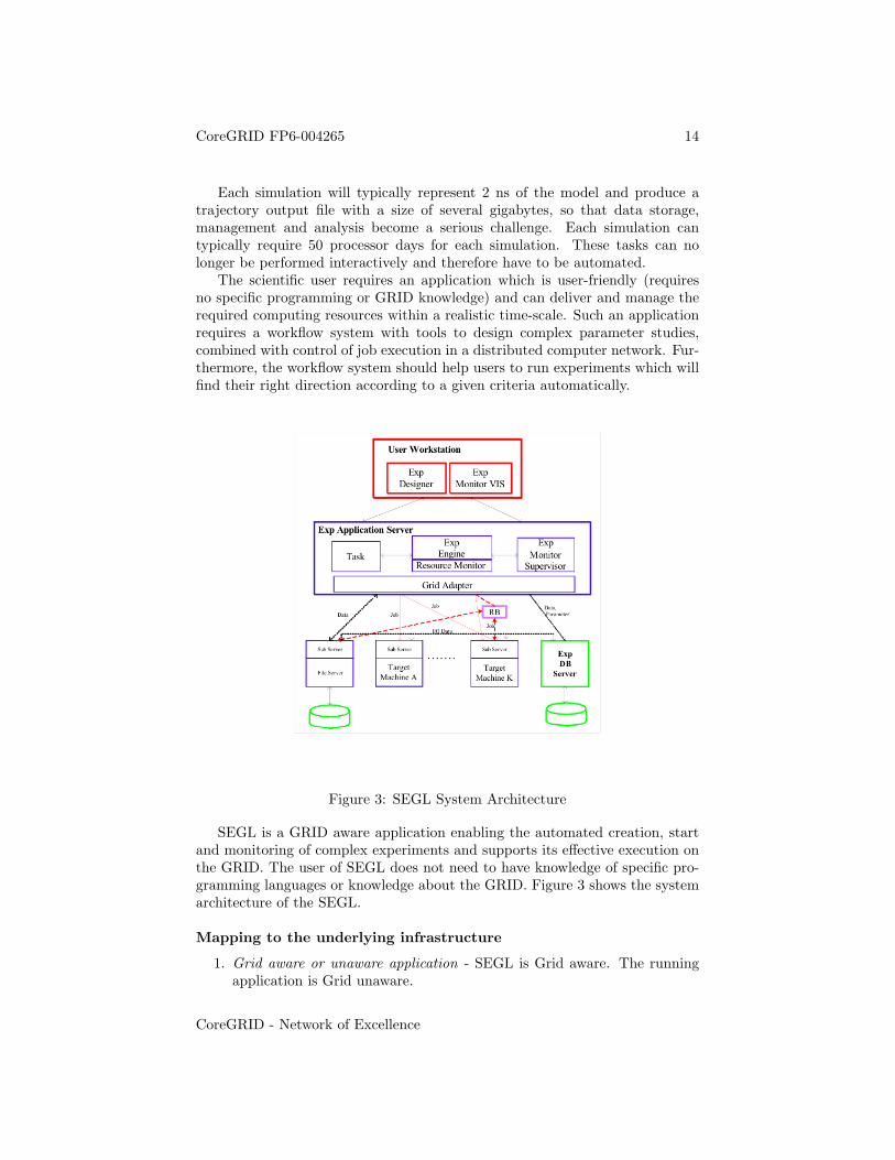
Each simulation will typically represent 2 ns of the model and produce atrajectory output file with a size of several gigabytes, so that data storage,management and analysis become a serious challenge. Each simulation cantypically require 50 processor days for each simulation. These tasks can nolonger be performed interactively and therefore have to be automated.
The scientific user requires an application which is user-friendly (requiresno specific programming or GRID knowledge) and can deliver and manage therequired computing resources within a realistic time-scale. Such an applicationrequires a workflow system with tools to design complex parameter studies,combined with control of job execution in a distributed computer network. Fur-thermore, the workflow system should help users to run experiments which willfind their right direction according to a given criteria automatically.
Figure 3: SEGL System Architecture
SEGL is a GRID aware application enabling the automated creation, startand monitoring of complex experiments and supports its effective execution onthe GRID. The user of SEGL does not need to have knowledge of specific pro-gramming languages or knowledge about the GRID. Figure 3 shows the systemarchitecture of the SEGL.
Mapping to the underlying infrastructure
1. Grid aware or unaware application - SEGL is Grid aware. The runningapplication is Grid unaware.
CoreGRID - Network of Excellence
CoreGRID FP6-004265 15
2. User Interface - Java graphical system of icons and nested windows torepresent workflow.
3. Type of infrastructure used - A Grid infrastructure is used.
4. Technologies Used - SEGL consists of three main components: the UserWorkstation (Client), the ExpApplicationServer (Server) and the ExpDB-Server (OODB). The system operates according to a Client-Server-Modelin which the ExpApplicationServer interacts with remote target computersusing a Grid Middleware Service such as UNICORE [28] and SSH. Inte-gration with Globus [8] is planned for the future. The implementation isbased on the Java 2 Platform Enterprise Edition (J2EE) [12] specificationand JBOSS Application Server [11]. The database used is an Object Ori-ented Database (OODB) with a library tailored to the application domainof the experiment.
5. Workflow requirements (representation) - The application will have work-flows between the calls to different codes Workflow is expressed using theGUI.
6. Runtime requirements - Is able to monitor the status of the applications.
3.8 GRID superscalar applications using BLAST. (UPC)
Projects: GRID Superscalar [9]
The application is algorithmically speaking simple, although complex interms of data size and required computation time. The objective is to com-pare - one by one - two sets of DNA (the mouse set with the human set). Toperform this comparison, both DNAs are split in several files and then each filein the mouse set is compared with each file of the human set using BLAST. Theapplication was initially designed in Perl using specific LoadLeveler functionali-ties. This application does not have special requirements regarding the resourcedistribution. The application can be run on a cluster or on a computationalgrid. The input files can be mirrored in different servers or sent to each serveron demand when required. Although the application may show performancereduction due to these file transfers, the cpu time consumed by the BLASTtask is coarse enough to hide the transfer time (overlapping file transfers withtask executions).
The original application was ported to the GRID superscalar version inc/c++ (this application is earlier for the development of the GRID superscalarPerl interface).
The use of GRID superscalar has simplified the programming of the appli-cation. the number of lines of the application has been reduced down to 10% ofthe original Perl application. Also, the development time was reduced by half,including the GRID superscalar learning process.
Mapping to the underlying infrastructure
CoreGRID - Network of Excellence
CoreGRID FP6-004265 16
1. Grid aware or unaware application - The original Perl application was‘cluster aware’. Most of the Perl scripts of the application were used toorganize the data, monitor which tasks have finished, which were pending,queuing new tasks, etc. The scripts were based on the prologue and epi-logue that can be run before/after each task submitted to a LoadLevelerqueuing system. The GRID superscalar application in c/c++ is grid un-aware. It can be run sequentially in a single cpu machine or exploit thetask concurrency in a computational grid. The GRID superscalar runtimetakes care of the file transfers, task-flow control and of all the grid relatedaspects.
2. User Interface - The user interface in the original program was a set of Perlscripts. In the final version, is a sequential program in c/c++. The callto the BLAST binary is wrapped in a function by means of the ‘system’call.
3. Type of infrastructure used - Original program, cluster. Final version,Grid.
4. Technologies used - For this case, the GRID superscalar version was usingGlobus 2.4.
5. Workflow requirements (representation) - The application defines a flatset of tasks without data/control dependencies (all BLAST evaluationsare independent of each other). However, potentially the user may wantto add a summarising task that depends on the finalisation of all theother tasks. Therefore, the requirements for workflow representation inthis application are very low.
6. Runtime requirements - The Biologists where interested in being able toknow the progress of the application. Being able to know the numberof tasks that have finished, the number of tasks being executed and thepending tasks is enough.
3.9 Chemical application - using GAMESS. (UPC)
Projects: GRID Superscalar [9]
The goal of the application in this case is the determination of molecularpotential energy hypersurfaces from the results of electronic structure calcula-tions.
This application is of interest in some areas of computational chemistry.Until recently the approach was to hire a student responsible of generating thedifferent input data and calling the electronic structure package one by one ina desktop computer.
As can be observed, this is highly inefficient. A group of researchers of theUniversidad de Castilla La Mancha (UCLM, SPAIN) has being collaborating
CoreGRID - Network of Excellence
CoreGRID FP6-004265 17
with the UPC during last two years in the application of Grid techniques totheir research and specially to their application.
to this end, a GRID superscalar application has been developed to solvethe problem of the generation of molecular potential energy hypersurfaces on acomputational Grid. The process is organized in three steps.
1. Molecular structure generation: this step consists of the generation ofthe set of molecular structures defining the potential energy hypersurface.The result is a large number of data files in format required by the desiredelectronic structure package.
2. Electronic structure calculation: one evaluation with the electronic struc-ture package is executed for each of the data files generated in step 1.Since the output of each of these evaluations is a large output file, a filter-ing process that obtains the required information (molecular coordinatesand total energy) is applied.
3. Data integration: the data generated by each of the calculations in step 2is integrated in a single ASCII file.
While steps 1 and 3 are not computationally intensive, the evaluation of thedifferent data of step 2 would have taken a long time in a sequential machine.
The application does not have any special requirement regarding the dis-tribution of the resources. Basically the data should be distributed from theclient machine to the servers and the results collected at the end of the execution.
Mapping to the underlying infrastructure
1. Grid aware or unaware application - The application is Grid unaware.
2. User Interface - Sequential application in c/c++. Calls to the GAMESSbinary are wrapped in a function by means of the ‘system’ call.
3. Type of infrastructure used - A Grid infrastructure is used.
4. Technologies used - For this case, the GRID superscalar version was usingGlobus 2.4.
5. Runtime requirements - It would be useful to have a monitoring/steeringinterface that allows one to observe the progress of the GAMESS exe-cutions and also to be able to interrupt some of the executions (for someinput data, GAMESS may not converge and the execution time lasts muchlonger than average. These evaluations are of no interest because are out-layers and therefore it is desirable to stop them).
Although a small monitoring tool has been designed by the UCLM team,the possibility of stopping outlayer evaluations is still not supported.
CoreGRID - Network of Excellence
CoreGRID FP6-004265 18
3.10 Performance Analysis Scenario. (UPC)
Projects: GRID Superscalar [9]
In this case the aim is to develop an automatic performance analysis tool for alarge (in number of CPUS and in terms of CPU consumption) MPI applications.
The performance analysis tools developped at UPC - Paraver, Dimemas, andParamedir - will be used together with other mathematical tools e.g. Mathe-matica.
The input to the application will be a Paraver tracefile of the MPI applica-tion to be analysed. The objective is to identify with an automatic process thepossible performance problems of the application (loss of performance in a givenCPU, loss of network performance, bottlenecks due to the data dependencies ofthe application, etc). It should be taken into account that the input tracefilecan be huge. The application is still under development at UPC by a PhDstudent with a mathematical background. The application may have networkbandwidth QoS requirements when visualizing shots of the Paraver file whereit has been identified as a problem.
Mapping to the underlying infrastructure
1. Grid aware or unaware application - The application is Grid unaware.
2. User Interface - C/C++ sequential application with functions wrappingcalls to external tools (Dimemas, paramedir,...) with the ‘system’ call.
3. Type of infrastructure used - A Grid infrastructure is used.
4. Technologies used - For this case, the GRID superscalar version was usingGlobus 2.4.
5. Workflow requirements (representation) - The application will have work-flows between the calls to different tools. However, no special representa-tion is initially required.
6. Runtime requirements - Currently not supported. However it will be usefulto be able to monitor the status of the applications and include possibleuser interaction through a steering interface.
3.11 Hospital Information System. (UoW)
Flexible Hospital Information system to make collection of patient data, patientmonitoring, allocation of staff around the hospital area, monitoring of staff andrecord updating (among other) easier and more efficient.
The management centre in each hospital presents the ideal entry point tothe whole system and will be the head of the higher-level virtual cluster forthis hospital [32]. Different virtual clusters are created for the different typesof users: doctors, nurses, hospital staff, security staff and so on. Each member
CoreGRID - Network of Excellence
CoreGRID FP6-004265 19
of the hospital team carries a lightweight mobile device like PDA or smart-phone. These devices are personalized for the specific person and have thenecessary platform components installed along with a set of metadata describingthe end user. Virtual clusters can also be established at the highest level betweenhospitals depending on the trust relationships. Note: in the rest of this textby saying cluster we mean the virtual cluster consisting of limited and mobiledevices not necessarily a cluster in its traditional form.
Doctors have access to large and possibly distributed across the departmentsdatabases of patient history. Doctors can update the patient records as well astheir own status locally and the main database is automatically updated pullingdata in a predefined way without the need for constant reporting. In the case ofintegrated sensor equipment for the measurement of vital patient measurements(like pulse, pressure, temperature and so on) some devices can act as proxiesfacilitating a special/proprietary communication protocol to retrieve sensor in-formation. The application to support the retrieval of data can be Grid unawareand there is no need for location and other details for the devices: the singleaggregator interface that provides the collection of data can be invoked using amirror function that will enable the collection of all data automatically. Nursesand practice doctors can have access to restricted views of the patient records,knowledge database to assist in diagnosis and more. Doctors and nurses canalso ask for help from other staff, providing information (like comments, photos,graphs etc.) and the system will automatically forward the request to all staffthat is experienced, skilful and available at that moment to answer the question.When an answer arrives again back at the proxy, it is automatically forwardedto the client with minimal human intervention. Applications to support staffallocation and management can also be Grid unaware as the relevant interfacecan be invoked with collective operation functionality in order to get locations,staff details (expertise, availability etc.), current status and other dynamic stateinformation, according to a supplied template. This way emergency situationscan be dealt with more efficiently and the overall hospital management is noweasier. Failures of any kind may trigger automatic staff reallocation accordingto the monitoring information, in order to have the best possible coverage andfastest response to situations. Available staff that can deal with the failure areautomatically informed in order to rectify the situation as soon as possible. Hu-man intervention in the management and allocation processes is kept in a verylow level, resulting in very fast responses.
On the highest level, trust relationships between the organizations definethe mobility support paradigms that will be used, for example, migration ofdata between the sites and the more specific virtual clusters. Mobility betweenvirtual clusters may trigger possible migrations depending on the applicationrequirements and the policies in use. Frequent checkpoints are cached in theproxy especially when a failure is predicted. Mobility also triggers proxy-to-proxy communication in this case so that the connection can remain with themobile node of interest unless a virtual cluster in the new domain doesnt existin which case checkpointing and migration will be used, again depending on theapplied policies. Client applications can access resources and services in a trans-
CoreGRID - Network of Excellence
CoreGRID FP6-004265 20
parent way not generally concerned with possible failure and location details.
Mapping to the underlying infrastructure
1. Grid aware or unaware application - There is grid unawareness for theapplication developer as the complexity of the virtual clusters is hiddenbehind the proxy. Possible distribution of job can be done automatically(assuming a suitable parallel/distributed programming model); interfacesfor mirrored and/or parallel execution are automatically made available;failures are detected internally and rectified immediately when this is pos-sible providing the illusion of a relatively reliable and stable environmenteven though the underlying core fabric layer is not really reliable but ratheris error-prone; critical data can be forwarded to a proxy cache in case ofa failure prediction or in predefined time intervals.
2. User Interface - The virtual cluster administrator interface consists oflocal as well as remote secure visual clients that make management ofaggregated services easy. Client user interface may consist of typical Gridportals and tools for job submission, service invocation, job monitoringand management.
3. Type of infrastructure used - Main infrastructure (if it exists) is a tradi-tional Grid system. Behind the proxy a virtual cluster of possibly mobileand wireless devices like PDAs, smart-phones, laptops, and possibly sen-sors (with an extra support for sensor connectivity and retrieving sensordata using proxies). The whole virtual cluster is only viewed as a one-hopextension to the Grid complete abstraction.A number of virtual clusters are created depending on the different userrequirements, credentials, service level agreements etc. Virtual clustersmay well be deployed in a hierarchical manner allowing for federations ofclusters, depending again on the usage, trust and security policies.Supporting the virtual cluster middleware, a component based core plat-form as specified by the CoreGRID component model and task WP7.1.The platform is reconfigurable and adaptable to changes in the executionenvironment.
4. Service representation - Virtual services that aggregate the underlyingresources may be exposed either as Web Services, WSRF Services, RMIactive objects or following the component model specified by CoreGRID.Services behind the proxy are exposed through component interfaces. Op-tionally they can be exposed as Web Services deployed in lightweight WSframeworks specially designed for limited devices (this is difficult as en-veloping XML request in SOAP can be expensive and not very efficient inthis case).
5. Workflow requirements (representation) - Dynamic, distributed workflowsthat may access many distributed data sources and cross many VO bound-aries.
CoreGRID - Network of Excellence
CoreGRID FP6-004265 21
6. Runtime requirements - Monitoring is based on the monitoring frameworkof our platform, consisting of installed agents in the cluster devices to mon-itor and report on all possible aspects like hardware, energy, software, de-pendencies, open connections and so on. Lower level steering is dealt withby the failure recovery and prediction system that can predict, detect, di-agnose and mask failures internal in the cluster, provide checkpointing andmigration support as well as logging and reporting. Application steeringis provided by the underlying components based platform. The platformis adaptable and reconfigurable so as to respond to higher-level changesin application requirements by reconfiguring application composition andoptimizing the components as well as the composition itself.
3.12 Legacy Systems as Grid Services. (CYFRONET)
Projects: Legacy-to-Grid Adaptation Framework [15]
In some scenarios, at some point of computation access to an external sys-tem such as a database, an external analysis system, a monitoring system, etc.,is necessary, for example, to fetch input, store output or perform analysis ofcollected information. Examples of such scenarios are the Gravitational WaveAnalysis (section 3.5) where the final output is stored in a database, the Molec-ular Dynamics Scenario 3.7 in which simulations generate huge amounts of datato be stored in databases, the Hospital Information System 3.11 where informa-tion about patients are stored in large databases and accessed or updated whennecessary. To enable flexible construction of workflows in such cases, legacy sys-tems need to be exposed as grid services. This can be achieved using the LGFLegacy-to-Grid Adaptation Framework. Using LGF, with minimum assistancefrom the developer, a legacy system, such as database, can be deployed as aweb/grid service and accessed through a WS-interface. In case of databases, itis important that the WS-interface for the database supports transactional in-teraction with a database. LGF supports transactional processing by exposinga standard set of WS-methods for transactional interactions if this is requested.Once a WSDL description for this interface is available and the service is de-ployed, the integration with a portal (in the sense of composing the legacysystem into a workflow) will be straightforward.
Mapping to the underlying infrastructure
1. Grid aware or unaware application - legacy system usually unaware.
2. User Interface - workflow composition tool from a grid portal.
3. Type of infrastructure used - Grid.
4. Service Representation - web service or WSRF
CoreGRID - Network of Excellence
CoreGRID FP6-004265 22
4 From User Requirement to Portal Design
In simple terms, a Grid Portal is a Web interface to the Grid. It provides a(secure) Web-based user interface to a collection of tools and services, whichsimplify how a user interacts with Grid primitives. Most current portal imple-mentations perform relatively primitive Grid capabilities, that is they are essen-tially execution and monitoring environments. Core portal capabilities typicallyinclude environment management, such as: authentication, profile personaliza-tion, administration of the creation of users and groups, and Grid functional-ity, such as: job submission, file management, information services, remote filebrowsing and job monitoring services. From the user scenarios above, we cansee a wide diversity and complexity of requirements not currently supportedmy most portals. We believe therefore that portals must support capabilitiesusually associated with Problem Solving Environments. This development willrequire more sophisticated user interfaces. From a non-functional perspective,it is required that these interfaces should conform to ISO standards for HCI andusability.
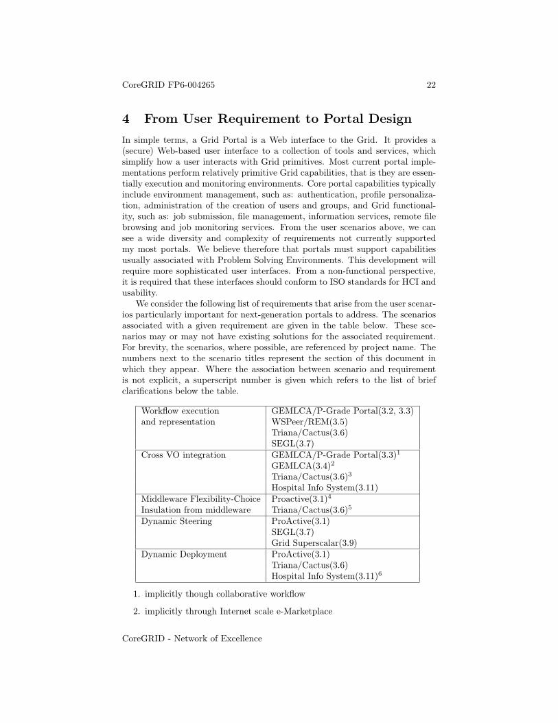
We consider the following list of requirements that arise from the user scenar-ios particularly important for next-generation portals to address. The scenariosassociated with a given requirement are given in the table below. These sce-narios may or may not have existing solutions for the associated requirement.For brevity, the scenarios, where possible, are referenced by project name. Thenumbers next to the scenario titles represent the section of this document inwhich they appear. Where the association between scenario and requirementis not explicit, a superscript number is given which refers to the list of briefclarifications below the table.
Workflow execution GEMLCA/P-Grade Portal(3.2, 3.3)and representation WSPeer/REM(3.5)
Triana/Cactus(3.6)SEGL(3.7)
Cross VO integration GEMLCA/P-Grade Portal(3.3)1
GEMLCA(3.4)2
Triana/Cactus(3.6)3
Hospital Info System(3.11)Middleware Flexibility-Choice Proactive(3.1)4
Insulation from middleware Triana/Cactus(3.6)5
Dynamic Steering ProActive(3.1)SEGL(3.7)Grid Superscalar(3.9)
Dynamic Deployment ProActive(3.1)Triana/Cactus(3.6)Hospital Info System(3.11)6
1. implicitly though collaborative workflow
2. implicitly through Internet scale e-Marketplace
CoreGRID - Network of Excellence
CoreGRID FP6-004265 23
3. implicitly through dynamic creation of workflow - i.e. search and discoveryof resources
4. implicitly through the ProActive deployment infrastructure
5. implicitly through dynamic creation of workflow - i.e. search and discoveryof resources
6. implicitly through migration
We elucidate each requirement below and offer some suggestions on howresearch efforts and further collaborations within CoreGrid can help addressthem.
4.1 Workflow Execution and Representation
Most portal implementations do not have the capacity to represent or executeworkflow. The collaboration between GEMLCA and the P-Grade portal is anotable exception. The research and lessons learnt in this collaboration need tofeed into the next stage of portal design. This process should be conducted inline with developments in the GGF Workflow Management Research Group toensure that the design specification follows emerging standards.
4.2 Cross VO integration
Most Grid activity currently operates within single VOs. This will have tochange if the vision of the Grid is to become a reality. However there are anumber of issues which arise from this, for example security and resource man-agement. SZTAKI has been conducting research into the latter (cross VO re-source management). This work needs to be considered. Likewise research intomore dynamic security models needs to be examined and conducted. The cur-rent GSI is too restrictive and static for some of the scenarios listed in Section 3,for example the scenario described in 3.6 which requires dynamic deploymentacross grids, and the scenario in 3.11 which requires security across mobile de-vices without static IP addresses.
4.3 Middleware Flexibility/Choice - Insulation from Mid-dleware
Most portals contain bindings to a specific middleware tools, e.g. Condor [3],Globus, etc but some of our user scenarios require the flexibility of switching orchoosing the type of middleware depending on the particular task or application.We therefore need to bridge this missing link between the application level andthe various grid middleware packages through the use of an application-orientedinterface to abstract the portal from needing to adjust its software to provideimplementation to changing grid resources, and middleware packages.
CoreGRID - Network of Excellence
CoreGRID FP6-004265 24
One example of such an interface is the GAT [6], which is designed to be easyto use for application developers, supports different programming languages andgrid middleware, and is oriented towards dynamic and adaptive grid-aware ap-plications. The developers of the GAT (GridLab [10]) have also been a key driverbehind the Simple API for Grid Applications (SAGA) group, a GGF standard-ization activity, to access a range grid capabilities, such as job submission, filemovement and registry of files in logical file servers.
4.4 Dynamic Steering
Real-world Dynamic Data-Driven Application Systems (DDDAS) are pervasivein the modern world. Applications range from industrial processes such aschemical plants or pipeline networks, engine modelling and control, through toscientific data analysis tasks within complex astrophysics experiments. DDDASsystems, such as our pipeline modeling scenario, described in Section 3.6, requirea flexible infrastructure to be able to make on-the-fly decisions about workflowand the reconfiguration of components. Future generation portals need to ad-dress these aspects to be able to allow the re-configurability of workflow andcomponents based on certain properties, typically from the current data con-tent. Further, users will need more interactivity with the executing componentsor workflow so that they can steer its direction based on expert knowledge i.e.the user will need to form part of that workflow. This area is particularly opento more research.
4.5 Dynamic Deployment
A major issue arising from the scenarios is the question of dynamic deployment.This raises issues again of security, and what constitutes a grid node (i.e. whatis expected of in terms of operating system, configuration etc). Work under-taken at UPC as well as new developments at FORTH-ICS, which allow thebundling and deployment of legacy codes need to be considered in the portaldesign. INRIA also have some experience with deploying Java code dynami-cally. Furthermore UoW have begun work on defining a dynamic deploymentstrategy. This area is as yet not subject to any standarisation. Therefore thesevarious approaches developed within CoreGrid institutes need to be analysedfor similarities and differences to enable the development of a generic dynamicdeployment interface. This may in itself lead to proposals regarding standardi-sation.
4.6 Portal Design
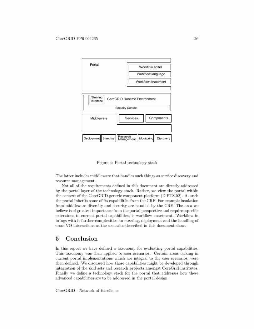
Figure 4 shows the proposed technology stack of the next-generation portal. Itis designed to integrate with the generic component platform architecture as de-fined in CoreGRID deliverable D.ETS.02. The primary gateway for the portal’scommunication with Grid components is through the CoreGRID Runtime Envi-ronment (here referred to as CRE) proposed in the generic component platform
CoreGRID - Network of Excellence
CoreGRID FP6-004265 25
(D.ETS.02). The stack addresses the advanced issues described in this section,either directly or through the CRE. In particular the issues of security, steeringand insulation from middleware are handled as part of the CRE.
The top layer defines the current portal capabilities - user log-in, job sub-mission and monitoring. Integrated into this layer is the workflow component.The portal acts as an interface to the layers below, in particular the CRE, forsimple, non-workflow based operations as well as more complex scenarios whichmake use of the workflow components.
The workflow sub-component is itself constructed of:
1. Workflow editor - this component consists of graphical elements that as awhole can be integrated into the web-based portal user-interface.
2. Workflow language - this component defines the workflow. The workflowis likely to be defined in XML. There are a number languages in existence- all are similar although some are more control-oriented, and others aremore data-oriented. While the Grid community may arrive at a standardworkflow language, this has not happened at the time of writing. There-fore, this component should also contain a translation module to handlemultiple definition languages.
3. Enactment engine. This component does the actual work of handling theworkflow. It must communicate this enactment back to the portal in orderfor the portal to pass data to the CRE discussed below.
The CRE acts as the glue between various underlying middleware capabili-ties. As shown in figure 4, a steering interface and security context are explicitlydefined by the runtime environment which the portal will make use of. For ex-ample, in handling cross VO workflow enactment, the portal will be able to usethe security context of the runtime environment to prepare certificate proxiesrepresenting identities mapping to different VOs. Because this security con-text is part of the runtime environment, it sits between the top layers and theunderlying middleware allowing messaging from the portal to the underlyingmiddleware to pass through this security sub-component. Depending on themiddleware target, this sub-component may either perform actual security re-lated operations such as handshaking or encryption, or may be entirely bypassedby the runtime environment. This approach allows security overhead to only beadded when required or requested.
The integration of the steering component into the CRE will give the portaldirect access to these capabilities. Therefore the portal needs to support thisfunctionality both directly in terms of user requests and in terms of dynamicchanges to the workflow sub-components.
Insulation from middleware implementations is provided by the CRE. Thisincludes the differing technologies used to expose capabilities such as service ori-ented representations and component oriented representations as well as func-tionality related to network characteristics such as node reliability and topology.
CoreGRID - Network of Excellence
CoreGRID FP6-004265 26
CoreGRID Runtime Environment
Services
PortalWorkflow editor
Workflow language
Workflow enactment
Components
Deployment Steering ResourceManagement Monitoring Discovery
Middleware
Steeringinterface
Security Context
Figure 4: Portal technology stack
The latter includes middleware that handles such things as service discovery andresource management.
Not all of the requirements defined in this document are directly addressedby the portal layer of the technology stack. Rather, we view the portal withinthe context of the CoreGRID generic component platform (D.ETS.02). As suchthe portal inherits some of its capabilities from the CRE. For example insulationfrom middleware diversity and security are handled by the CRE. The area webelieve is of greatest importance from the portal perspective and requires specificextensions to current portal capabilities, is workflow enactment. Workflow inbrings with it further complexities for steering, deployment and the handling ofcross VO interactions as the scenarios described in this document show.
5 Conclusion
In this report we have defined a taxonomy for evaluating portal capabilities.This taxonomy was then applied to user scenarios. Certain areas lacking incurrent portal implementations which are integral to the user scenarios, werethen defined. We discussed how these capabilities might be developed throughintegration of the skill sets and research projects amongst CoreGrid institutes.Finally we define a technology stack for the portal that addresses how theseadvanced capabilities are to be addressed in the portal design.
CoreGRID - Network of Excellence
CoreGRID FP6-004265 27
References
[1] BLAST - Basic Local Alignment Search Tool, seehttp://www.sp.uconn.edu/ mcb232vc/blast.html
[2] Cactus see http://www.cactuscode.org/
[3] The Condor Project see http://www.cs.wisc.edu/pkilab/condor/
[4] EGEE GLite see http://glite.web.cern.ch/glite/
[5] GAMESS - The General Atomic and Molecular Electronic Structure Sys-tem, see http://www.msg.ameslab.gov/GAMESS/GAMESS.html
[6] Gabrielle Allen, Kelly Davis, Tom Goodale, Andrei Hutanu, HartmutKaiser, Thilo Kielmann, Andre Merzky, Rob van Nieuwpoort, AlexanderReinefeld, Florian Schintke, Thorsten Schutt, Ed Seidel, Brygg Ullmer. TheGrid Application Toolkit: Towards Generic and Easy Application Program-ming Interfaces for the Grid. Proceedings of the IEEE, Vol. 93, No. 3, pp.534–550, March 2005.
[7] GEMLCA: Grid Execution Management for Legacy Code Architecture, seehttp://www.cpc.wmin.ac.uk/gemlca/
[8] The Globus Alliance url:http://www.globus.org
[9] Rosa M. Badia, Jesus Labarta, Raul Sirvent, Josep M. Perez, Jose M. Celaand Rogeli Grima, Programming Grid Applications with GRID SuperscalarJournal of Grid Computing, Vol. 1, No. 2, 2003, pp. 151 - 170.
[10] Allen G, Davis K, Dolkas K, Doulamis N, Goodale T, Kielmann T, MerzkyA, Nabrzyski J, Pukacki J, Radke T, Russell M, Seidel E, Shalf J and TaylorI (2003). Enabling Applications on theGrid: A GridLab Overview, JHPCASpecial issue on Grid Computing: Infrastructure and Applications, August2003.
[11] JBOSS Application Server see http://www.jboss.com/products/jbossas
[12] J2EE - Java 2 Platform Enterprise Editionseehttp://java.sun.com/j2ee/index.jsp
[13] JStyx - Reading e-Science Centre, UK, see http://jstyx.sourceforge.net
[14] LAL - LSC Algorithm Library, see http://www.lsc-group.phys.uwm.edu/daswg/projects/lal.html
[15] B. Balis, M. Bubak, and M. Wegiel. A Solution for Adaptating LegacyCode as Web Services. In Proc. Workshop on Component Models andSystems for Grid Applications. 18th Annual ACM International Con-ference on Supercomputing, Saint-Malo, France, July 2004. Kluwer. seehttp://www.icsr.agh.edu.pl/lgf
CoreGRID - Network of Excellence
CoreGRID FP6-004265 28
[16] MEANDER - The MEsoscale Analysis Nowcasting and DEcision Routines,A. Horvath: Nowcasting System of the Hungarian Meteorological Servce,Fifth European Conference on Applications of Meterorology, OMSZ Bu-dapest, 2001, pp.13.
[17] NCBI National Center for Biotechnology Information seehttp://www.ncbi.nlm.nih.gov/
[18] OASIS Open see http://www.oasis-open.org
[19] Foster I, Kesselman C, Nick J and Tuecke S (2002) The Physiology ofthe Grid: An Open Grid Services Architecture for Distributed SystemsIntegration, see http://www.globus.org/research/papers/ogsa.pdf
[20] P-Grade Portal , see http://www.lpds.sztaki.hu/pgportal/
[21] ProActive, see http://www-sop.inria.fr/oasis/ProActive/ (2002) The Phys-iology of the Grid: An Open Grid Services Architecture for DistributedSystems Integration, see http://www.globus.org/research/papers/ogsa.pdf
[22] REM - Remote Execution and Monitoring http://carv.ics.forth.gr
[23] Natalia Currle-Linde, Fabian Bs, Peggy Lindner , Jurgen Pleiss, MichaelM. Resch , A Management System for Complex Parameter Studies and Ex-periments in Grid Computing,accepted for publication PDCS 2004 - Inter-national Conference on Parallel and Distributed Computing and Systems’,MIT Cambridge, MA, 2004.
[24] Natalia Currle-Linde, Uwe Kuester, Michael M. Resch, Benedetto Risio:Science Experimental Grid Laboratory (SEGL) Dynamic Parameter Studyin Distributed Systems, accepted for ParCo -Parallel Computing, Spain2005.
[25] GridEngine see http://gridengine.sunsource.net/
[26] SWIG - Simple Wrapper Interface Generator see http://www.swig.org/
[27] Triana, see http://www.trianacode.org
[28] UNICORE see http://www.unicore.org/
[29] WS-Routing see msdn.microsoft.com/library/ en-us/dnglobspec/html/ws-routing.asp
[30] WSPeer, see http://www.wspeer.org/
[31] The WS-Resource Framework home page, see http://www.globus.org/wsrf/
[32] Isaiadis, S. and Getov, V., A Lightweight Platform for Integration of MobileDevices into Pervasive Grids, in L.T.Yang et al. (Eds.): 1st InternationlConference on High Performance Computing and Communications, Sor-rento, Italy, Sep 2005, LNCS 3726, pp. 1058-1063, Springer-Verlag, 2005
CoreGRID - Network of Excellence