Embed Size (px)
Citation preview
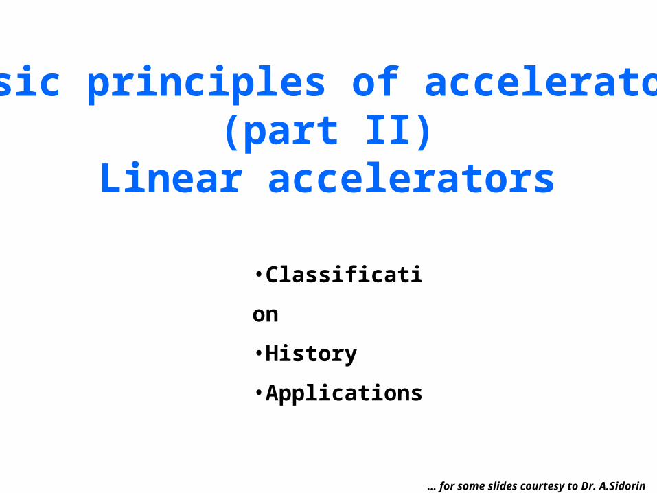
Basic principles of accelerators(part II)
Linear accelerators
•Classification
•History
•Applications
… for some slides courtesy to Dr. A.Sidorin
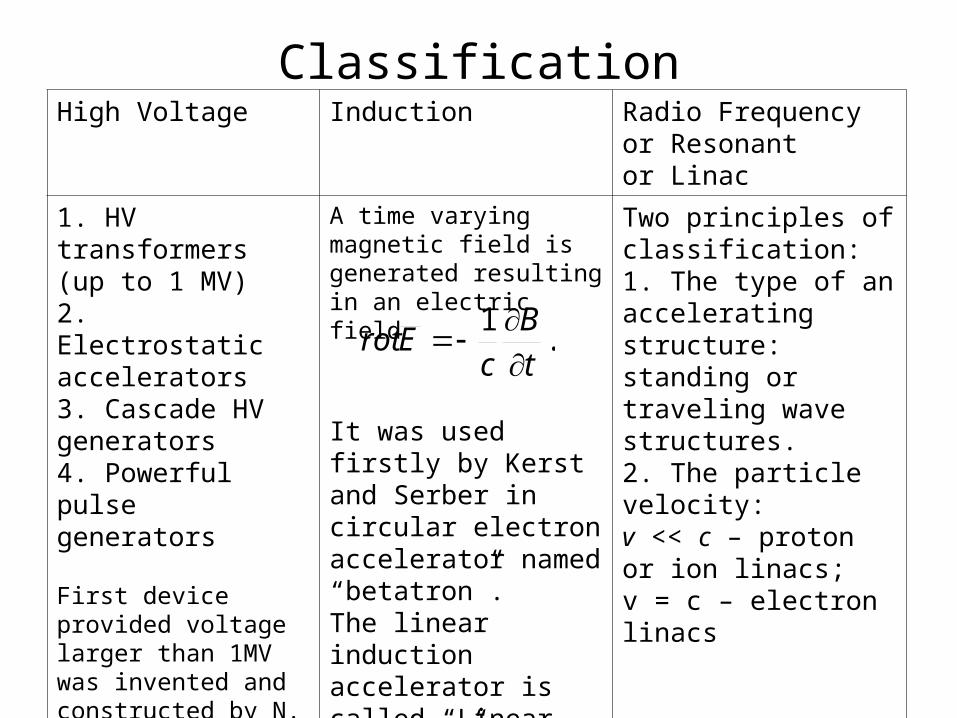
ClassificationHigh Voltage Induction Radio Frequency
or Resonantor Linac
1. HV transformers (up to 1 MV)2. Electrostatic accelerators3. Cascade HV generators4. Powerful pulse generators
First device provided voltage larger than 1MV was invented and constructed by N. Tesla in 1896.
A time varying magnetic field is generated resulting in an electric field
It was used firstly by Kerst and Serber in circular electron accelerator named “betatron”.The linear induction accelerator is called “Linear betatron”
Two principles of classification:1. The type of an accelerating structure: standing or traveling wave structures.2. The particle velocity:v << c – proton or ion linacs;v = c – electron linacs
.1
t
B
cErot
3
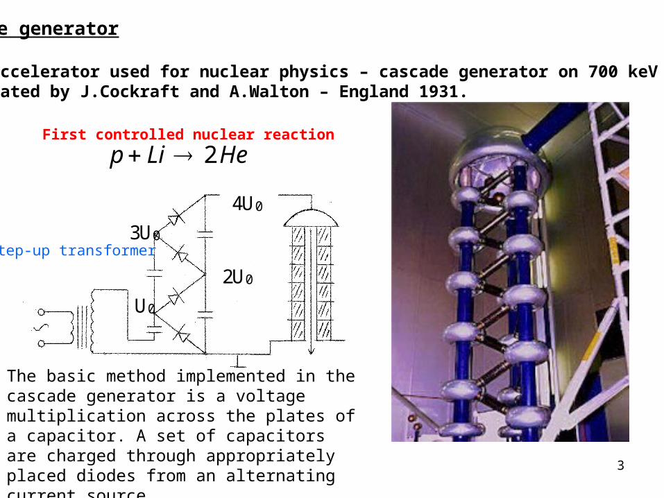
Cascade generator
First accelerator used for nuclear physics – cascade generator on 700 keV energywas created by J.Cockraft and A.Walton – England 1931.
U0
2U0
3U0
4U0
HeLip 2First controlled nuclear reaction
Step-up transformer
The basic method implemented in the cascade generator is a voltage multiplication across the plates of a capacitor. A set of capacitors are charged through appropriately placed diodes from an alternating current source
4
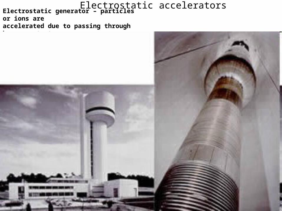
Van de Graaf (1931) generator
Electrostatic generator – particles or ions are accelerated due to passing through huge constant potential V (which reach magnitude up to 20 MV). Particle having charge Ze takes in such an accelerator kinetic energy T=ZeV. The great advantage of such a machine – continuous very intensive and very stable in energy (0,01 %) accelerated beam. Beam current is about several mA.
metal brush takes electrons from the high voltage electrode
moving rubber tape delivers positive charge
positively chargedmetal brush takes electrons from the tape
Voltage source
negatively chargedmetal plate
Isolatingcolumn
1937, St. Bartholomew’s Hospital, London, 1 MeV HV accelerator
Electrostatic accelerators
First medicine application
5
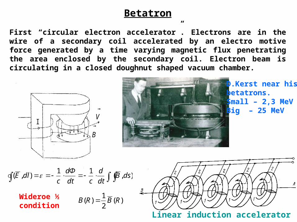
Betatron
First “circular electron accelerator”. Electrons are in the wire of a secondary coil accelerated by an electro motive force generated by a time varying magnetic flux penetrating the area enclosed by the secondary coil. Electron beam is circulating in a closed doughnut shaped vacuum chamber.
I V
B
D.Kerst near hisbetatrons.Small – 2,3 MeVBig – 25 MeV
),(11
),( dsBdt
d
cdt
dФ
cdlE
)(2
1)( RBRB Wideroe ½
conditionLinear induction accelerator
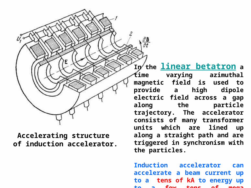
Accelerating structure of induction accelerator.
In the linear betatron a time varying azimuthal magnetic field is used to provide a high dipole electric field across a gap along the particle trajectory. The accelerator consists of many transformer units which are lined up along a straight path and are triggered in synchronism with the particles.
Induction accelerator can accelerate a beam current up to a tens of kA to energy up to a few tens of mega electron volts.
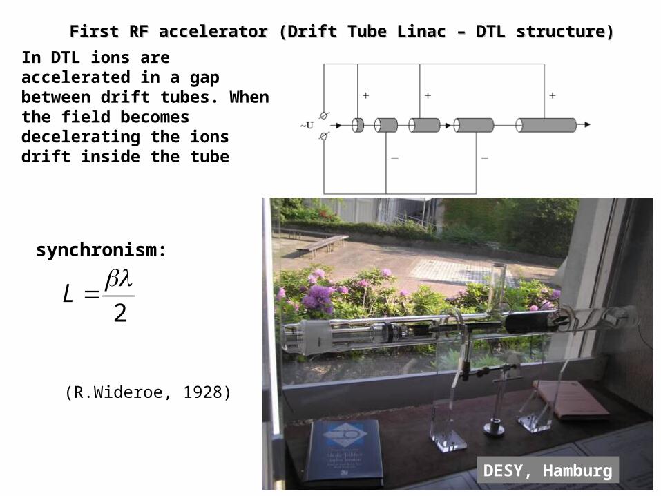
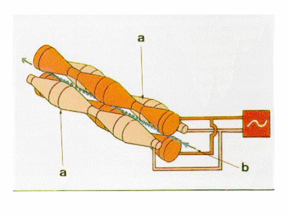
First RF accelerator (Drift Tube Linac – DTL structure)First RF accelerator (Drift Tube Linac – DTL structure)
In DTL ions are accelerated in a gap between drift tubes. When the field becomes decelerating the ions drift inside the tube
2
L
synchronism:
DESY, Hamburg
(R.Wideroe, 1928)
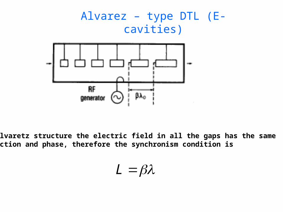
Alvarez – type DTL (E-cavities)
In Alvaretz structure the electric field in all the gaps has the same direction and phase, therefore the synchronism condition is
L
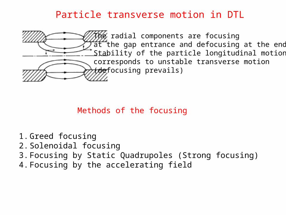
The radial components are focusing at the gap entrance and defocusing at the end.Stability of the particle longitudinal motioncorresponds to unstable transverse motion(defocusing prevails)
Particle transverse motion in DTL
1. Greed focusing2. Solenoidal focusing3. Focusing by Static Quadrupoles (Strong focusing)4. Focusing by the accelerating field
Methods of the focusing
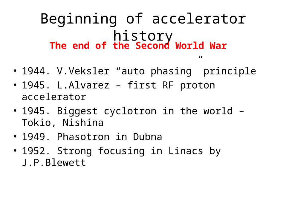
Beginning of accelerator history
• 1944. V.Veksler “auto phasing” principle• 1945. L.Alvarez – first RF proton accelerator • 1945. Biggest cyclotron in the world – Tokio,
Nishina• 1949. Phasotron in Dubna• 1952. Strong focusing in Linacs by J.P.Blewett
The end of the Second World War
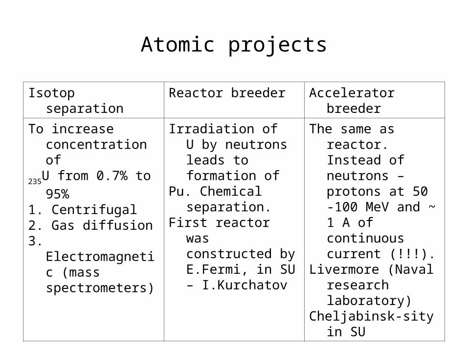
Atomic projects
Isotop separation Reactor breeder Accelerator breeder
To increase concentration of
235U from 0.7% to 95%
1. Centrifugal2. Gas diffusion3. Electromagnetic
(mass spectrometers)
Irradiation of U by neutrons leads to formation of
Pu. Chemical separation.First reactor was
constructed by E.Fermi, in SU – I.Kurchatov
The same as reactor. Instead of neutrons – protons at 50 -100 MeV and ~ 1 A of continuous current (!!!).
Livermore (Naval research laboratory)
Cheljabinsk-sity in SU
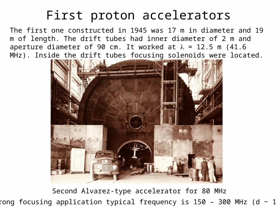
First proton acceleratorsThe first one constructed in 1945 was 17 m in diameter and 19 m of length. The drift tubes had inner diameter of 2 m and aperture diameter of 90 cm. It worked at = 12.5 m (41.6 MHz). Inside the drift tubes focusing solenoids were located.
Second Alvarez-type accelerator for 80 MHz
After strong focusing application typical frequency is 150 – 300 MHz (d ~ 1.5 – 3 m)
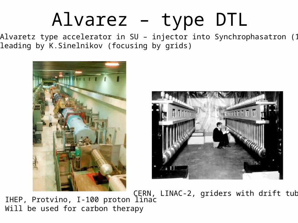
Alvarez – type DTL
CERN, LINAC-2, griders with drift tubes.IHEP, Protvino, I-100 proton linacWill be used for carbon therapy
First Alvaretz type accelerator in SU – injector into Synchrophasatron (1957)under leading by K.Sinelnikov (focusing by grids)
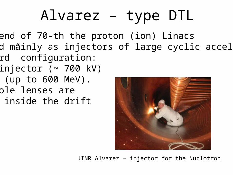
Alvarez – type DTLTo the end of 70-th the proton (ion) Linacs are used mainly as injectors of large cyclic accelerators.“Standard” configuration:HV foreinjector (~ 700 kV)Alvarez (up to 600 MeV).Quadrupole lenses arelocated inside the drifttubes
JINR Alvarez – injector for the Nuclotron
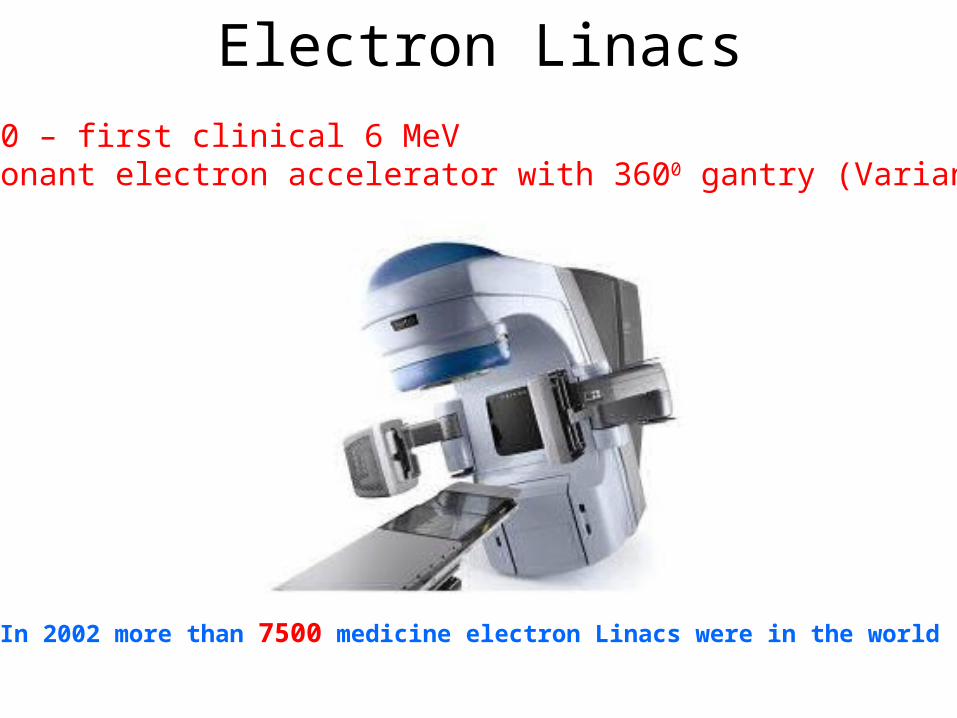
Electron Linacs1960 – first clinical 6 MeV resonant electron accelerator with 3600 gantry (Varian)
In 2002 more than 7500 medicine electron Linacs were in the world
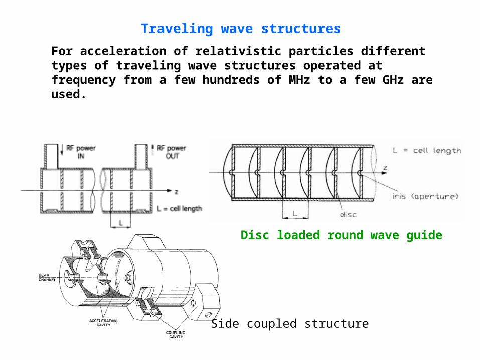
Disc loaded round wave guide
Traveling wave structures
For acceleration of relativistic particles different types of traveling wave structures operated at frequency from a few hundreds of MHz to a few GHz are used.
Side coupled structure
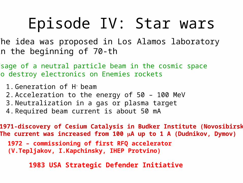
Episode IV: Star warsThe idea was proposed in Los Alamos laboratory in the beginning of 70-th
1. Generation of H- beam 2. Acceleration to the energy of 50 – 100 MeV3. Neutralization in a gas or plasma target4. Required beam current is about 50 mA
Usage of a neutral particle beam in the cosmic space to destroy electronics on Enemies rockets
1971-discovery of Cesium Catalysis in Budker Institute (Novosibirsk):The current was increased from 100 A up to 1 A (Dudnikov, Dymov)
1972 – commissioning of first RFQ accelerator (V.Tepljakov, I.Kapchinsky, IHEP Protvino)
1983 USA Strategic Defender Initiative
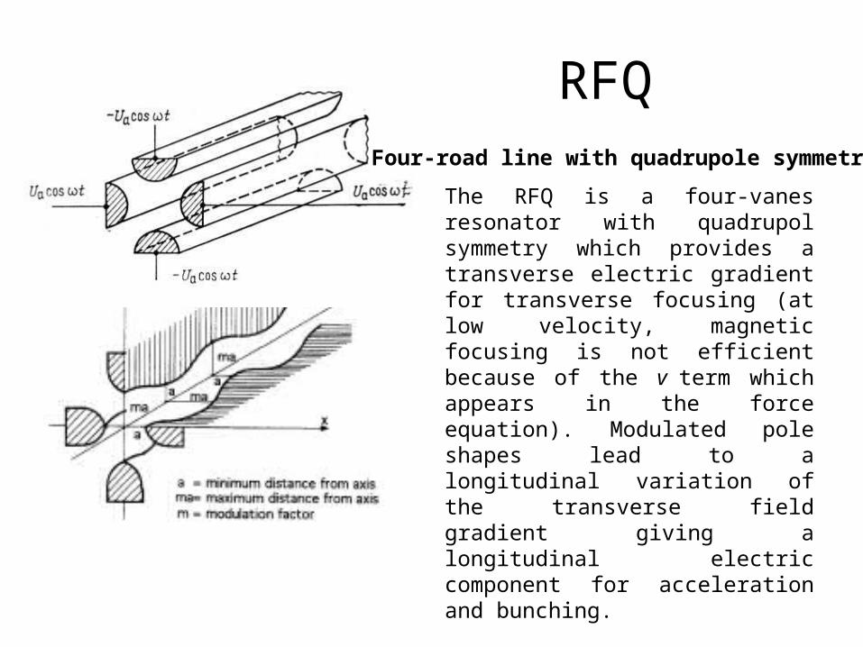
RFQFour-road line with quadrupole symmetry
The RFQ is a four-vanes resonator with quadrupol symmetry which provides a transverse electric gradient for transverse focusing (at low velocity, magnetic focusing is not efficient because of the v term which appears in the force equation). Modulated pole shapes lead to a longitudinal variation of the transverse field gradient giving a longitudinal electric component for acceleration and bunching.
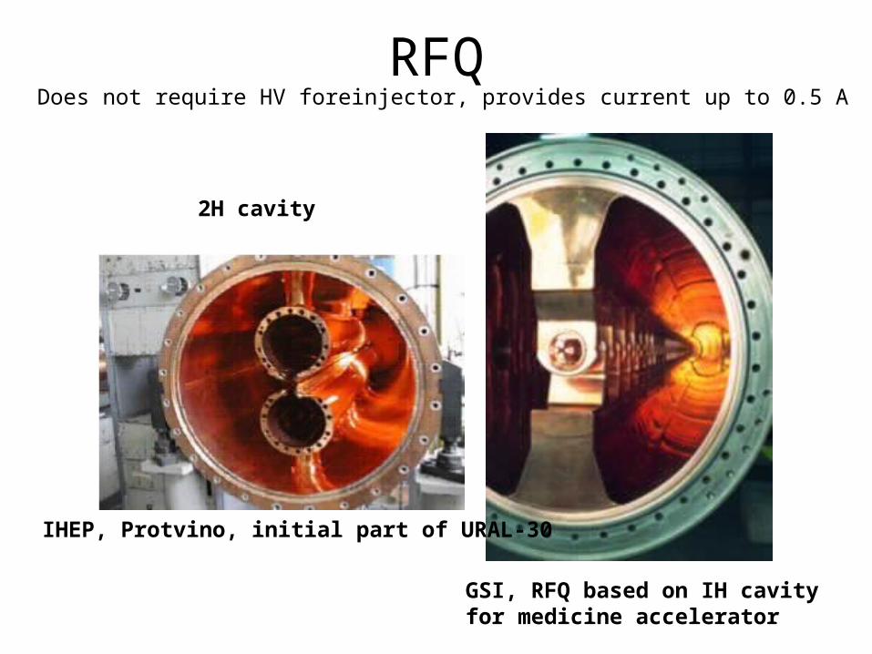
RFQ
IHEP, Protvino, initial part of URAL-30
GSI, RFQ based on IH cavityfor medicine accelerator
2H cavity
Does not require HV foreinjector, provides current up to 0.5 A
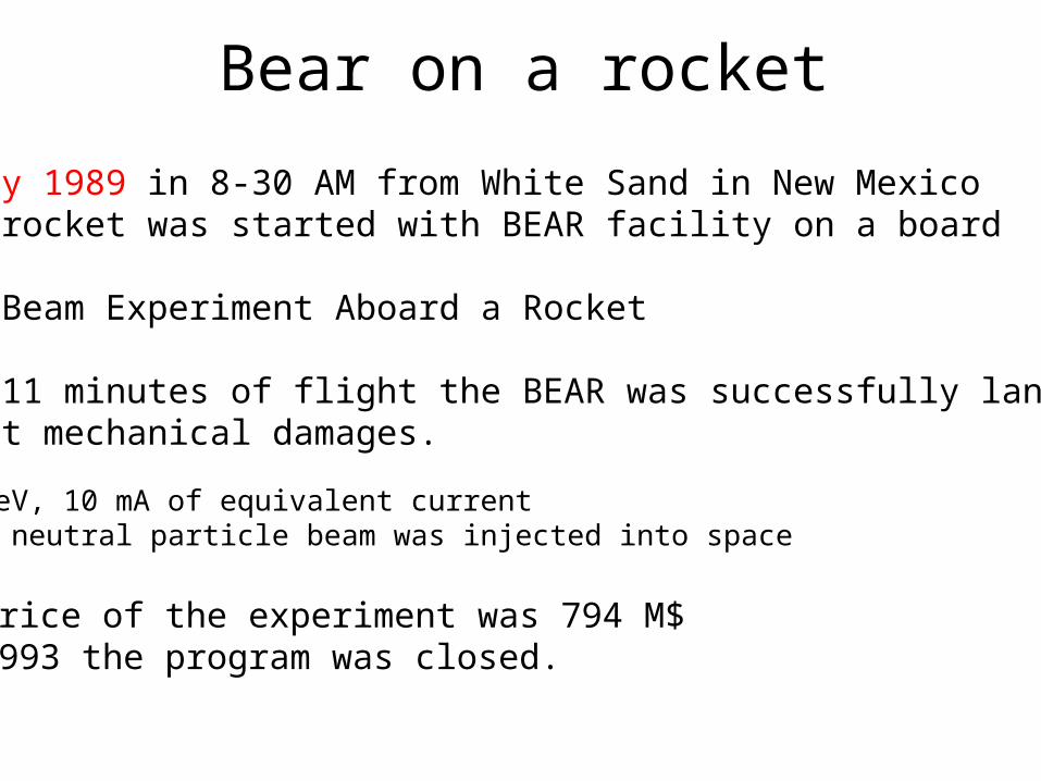
Bear on a rocket
13 July 1989 in 8-30 AM from White Sand in New Mexico Areas rocket was started with BEAR facility on a board
BEAR –Beam Experiment Aboard a Rocket
After 11 minutes of flight the BEAR was successfully landed without mechanical damages.
1 MeV, 10 mA of equivalent current the neutral particle beam was injected into space
Price of the experiment was 794 M$1993 the program was closed.
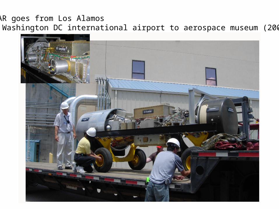
BEAR goes from Los Alamosto Washington DC international airport to aerospace museum (2006)
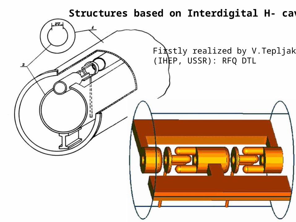
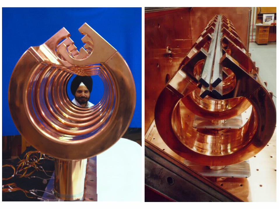
Structures based on Interdigital H- cavity
Firstly realized by V.Tepljakov(IHEP, USSR): RFQ DTL
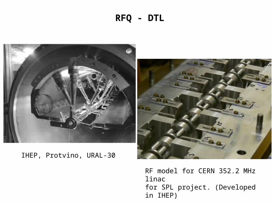
RFQ - DTL
IHEP, Protvino, URAL-30
RF model for CERN 352.2 MHz linac for SPL project. (Developed in IHEP)
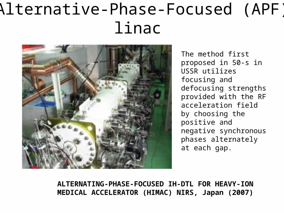
Alternative-Phase-Focused (APF) linac
ALTERNATING-PHASE-FOCUSED IH-DTL FOR HEAVY-IONMEDICAL ACCELERATOR (HIMAC) NIRS, Japan (2007)
The method first proposed in 50-s in USSR utilizes focusing and defocusing strengths provided with the RF acceleration field by choosing the positive and negative synchronous phases alternately at each gap.
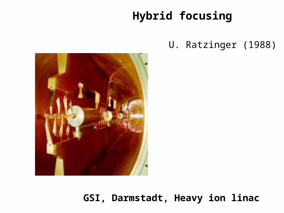
GSI, Darmstadt, Heavy ion linac
Hybrid focusing
U. Ratzinger (1988)
28
電場
(陽 )電子
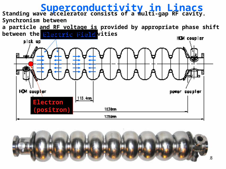
Superconductivity in Linacs
Electric Field
Electron (positron)
Standing wave accelerator consists of a multi-gap RF cavity. Synchronism between a particle and RF voltage is provided by appropriate phase shift between the fields in the cavities
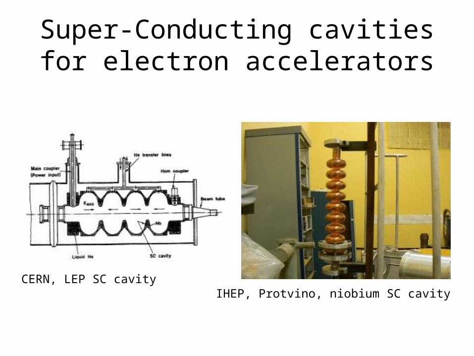
Super-Conducting cavities for electron accelerators
CERN, LEP SC cavityIHEP, Protvino, niobium SC cavity
30
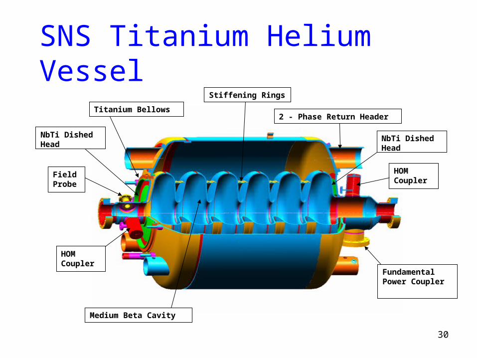
SNS Titanium Helium Vessel
Medium Beta Cavity
Fundamental Power Coupler
HOM Coupler
HOM Coupler
Field Probe
NbTi Dished Head
Titanium Bellows
NbTi Dished Head
Stiffening Rings
2 - Phase Return Header
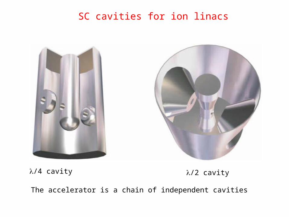
/4 cavity /2 cavity
SC cavities for ion linacs
The accelerator is a chain of independent cavities
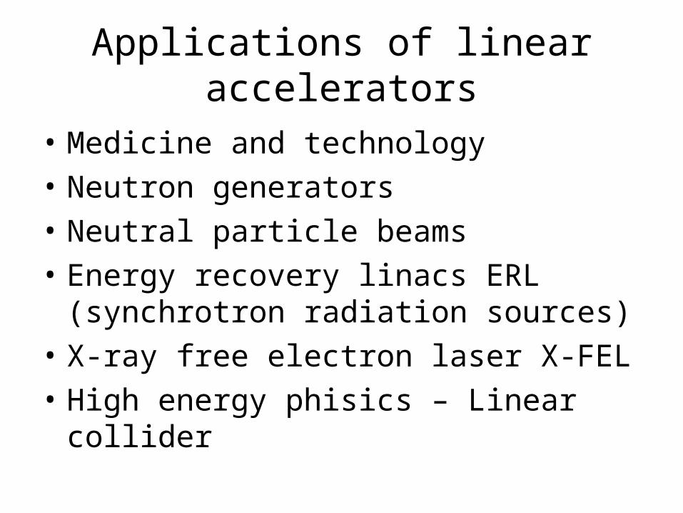
Applications of linear accelerators
• Medicine and technology
• Neutron generators
• Neutral particle beams
• Energy recovery linacs ERL (synchrotron radiation sources)
• X-ray free electron laser X-FEL
• High energy phisics – Linear collider
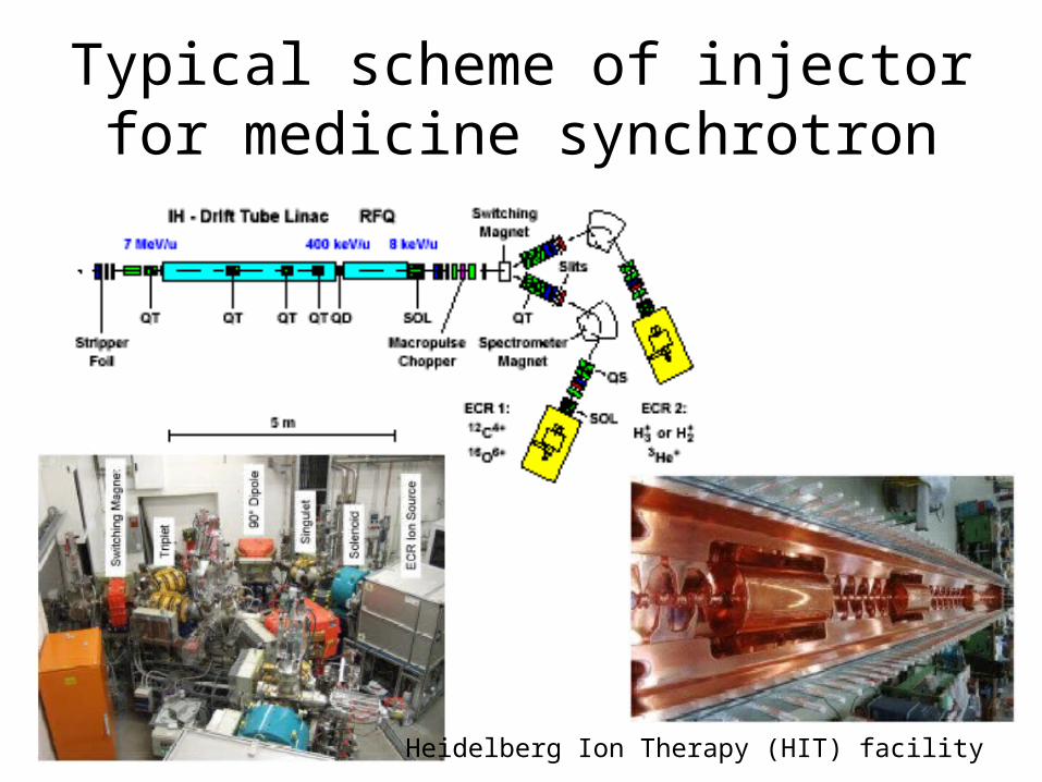
Typical scheme of injector for medicine synchrotron
Heidelberg Ion Therapy (HIT) facility
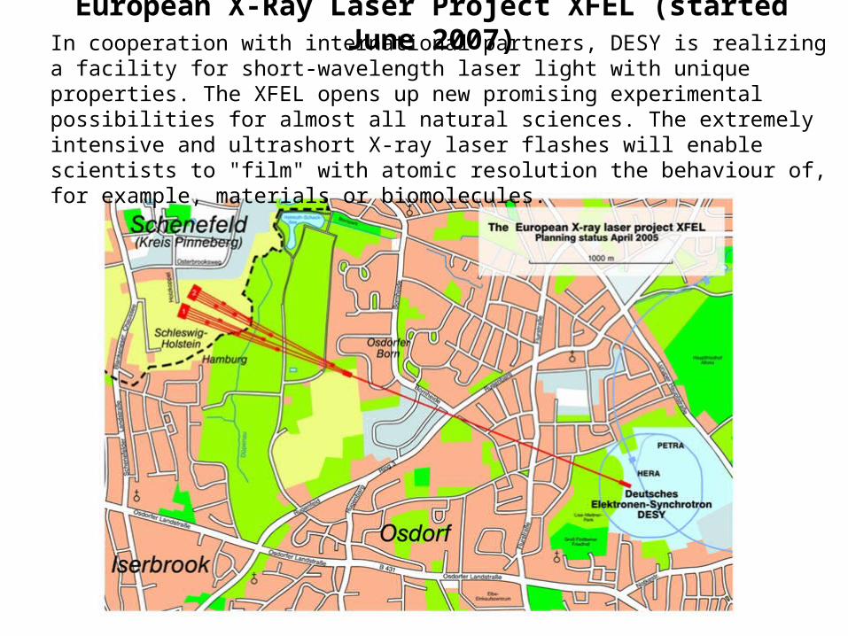
European X-Ray Laser Project XFEL (started June 2007)
In cooperation with international partners, DESY is realizing a facility for short-wavelength laser light with unique properties. The XFEL opens up new promising experimental possibilities for almost all natural sciences. The extremely intensive and ultrashort X-ray laser flashes will enable scientists to "film" with atomic resolution the behaviour of, for example, materials or biomolecules.
Linear colliders
• Stanford Linear Collider - SLC
• CLIC – Compact Linear Collider
• ILC – International Linear Collider
36
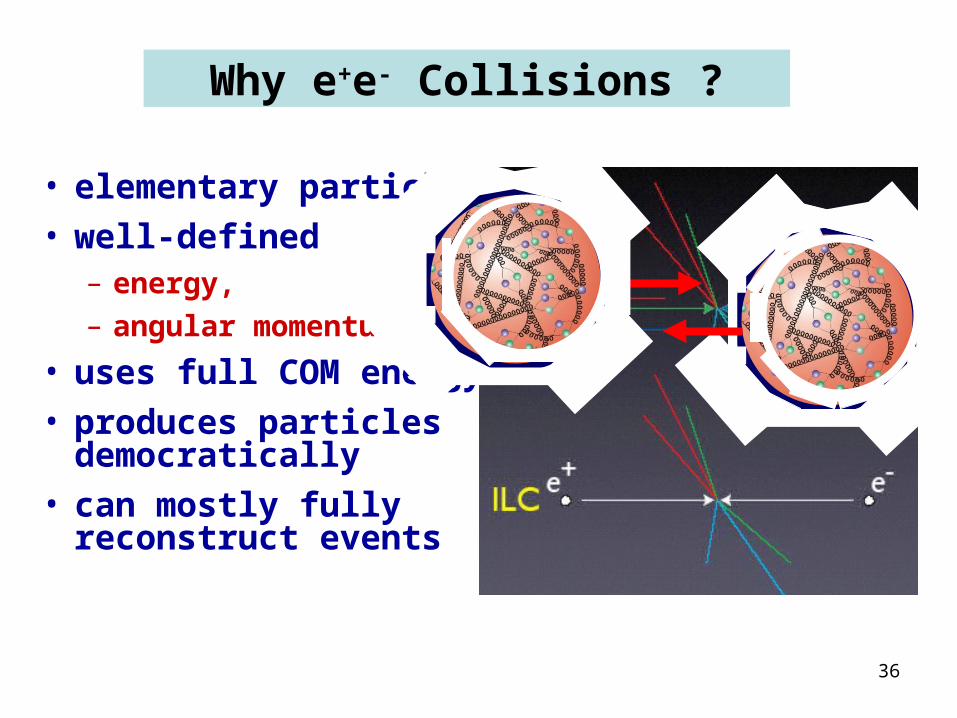
Why e+e- Collisions ?
• elementary particles
• well-defined – energy,
– angular momentum
• uses full COM energy
• produces particles democratically
• can mostly fully reconstruct events
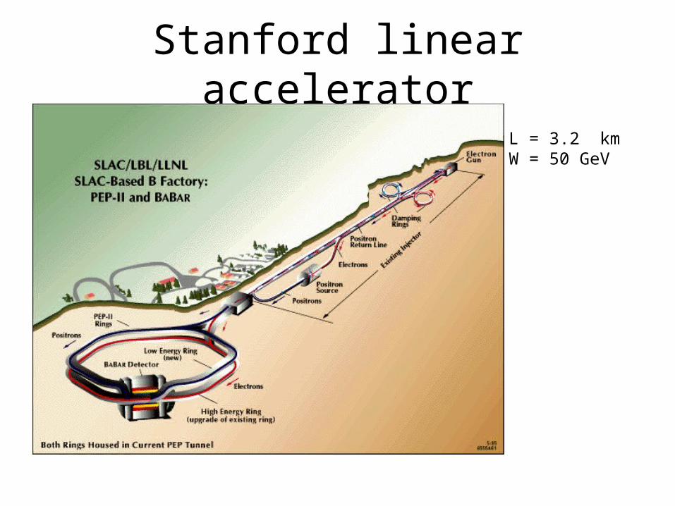
Stanford linear accelerator
L = 3.2 kmW = 50 GeV
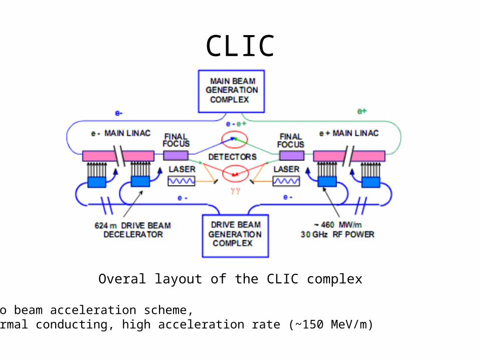
CLIC
Overal layout of the CLIC complex
Two beam acceleration scheme, normal conducting, high acceleration rate (~150 MeV/m)
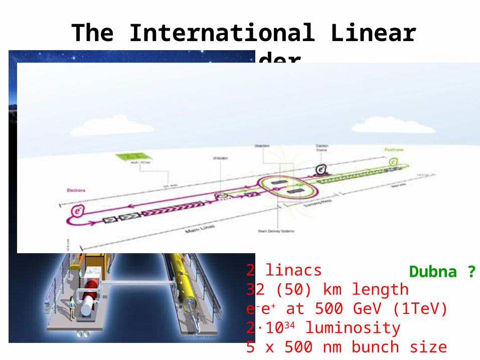
The International Linear Collider
2 linacs32 (50) km lengthe-e+ at 500 GeV (1TeV)2·1034 luminosity5 x 500 nm bunch size
Dubna ?
40
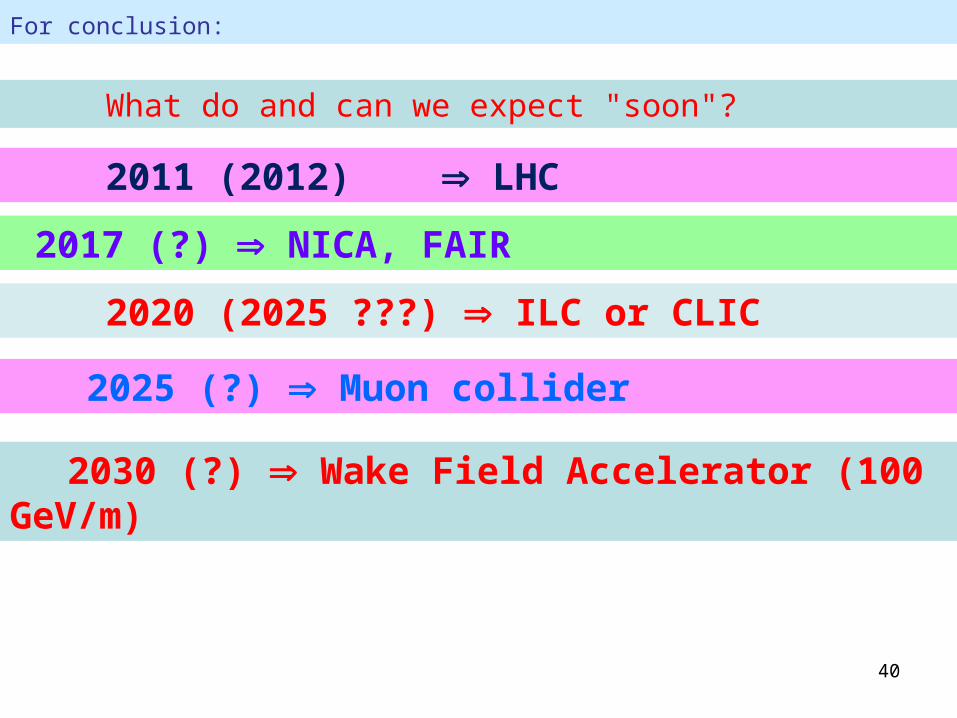
For conclusion:
What do and can we expect "soon"?
2011 (2012) LHC
2017 (?) NICA, FAIR
2020 (2025 ???) ILC or CLIC
2025 (?) Muon collider
2030 (?) Wake Field Accelerator (100 GeV/m)
41
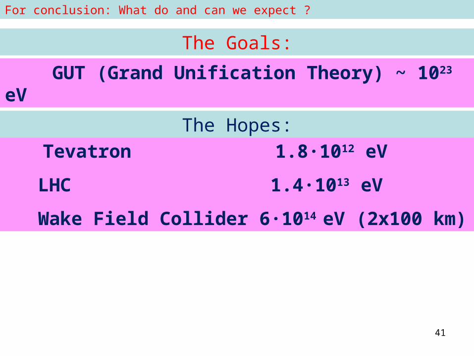
The Goals:
GUT (Grand Unification Theory) ~ 1023 eV
Tevatron 1.8·1012 eV
LHC 1.4·1013 eV
Wake Field Collider 6·1014 eV (2x100 km)
The Hopes:
For conclusion: What do and can we expect ?