Embed Size (px)
Citation preview
12
GeoScience Engineering Volume LXIV (2018), No. 2
http://gse.vsb.cz p. 12-21, ISSN 1802-5420
BASIC PRINCIPLES OF HYDROSTATIC LEVELLING
Jiří POSPÍŠIL, Rostislav DANDOŠ
Department of Geodesy and Mine Surveying, Faculty of Mining and Geology, VŠB-TU Ostrava,
17. listopadu 15, Ostrava-Poruba, tel. (+420) 597 323 208
e-mail: [email protected]
ABSTRACT
The paper aims to introduce the distribution, history and the basic physical principles hydrostatic
levelling. The principle of this method is based on known law of connected vessels filled with fluid. Well
known equipment is surface water level, the height of the surface is deducted on millimetre scale. There
are currently used devices that allow deducting with accuracy of 0.01 mm.
Keywords: levelling, height, hydrostatic pressure
1 INTRODUCTION
Hydrostatic levelling is one of many methods used for definition of elevation. This term is usually used
for all systems using for the elevation definition fluids in connected vessels. These methods are divided as:
hydrostatic,
hydrodynamic,
hydromechanical.
All stated methods are based on the same principles of hydrostatics and hydrodynamics. The methods
vary in the way of realization of a measuring process.
Hydrostatic levelling observes surface of still fluid. These systems measure elevation in a scope of circa
10 cm, they have high accuracy from 0.05 mm to 0.01 mm. Nowadays the height of surface is mostly defined
automatically by various types of sensors, contact, capacity, ultrasound or floating.
Hydrodynamic levelling uses for the definition of elevation flowing fluid based on Bernoulli quotation.
Measuring systems may be similar to systems for hydrostatic levelling. Equipment for hydrodynamic levelling
reaches accuracy 0.01 mm to 2.5 mm. This category may cover also levelling defining elevation based on sea
surface elevation among land and the closest islands. This way may be used for transferring the heights for tens
of kilometers distance. The method was used e.g. at height connection of British continent over English Channel.
The method of hydromechanical levelling defines elevation based on hydrostatic pressure in fluid column
in connected vessels. Deriving the hydrostatic pressure quotation, described into more details in the following
chapter, it can be stated the hydrostatic pressure is independent on the value of the fluid in a vessel but on a
height of a water column. The accuracy of these systems states with a determinative deviation 1 cm in which
states accuracy of 2.2 cm. [1, 2]
The usage of hydrometric levelling states e.g. when measuring roads, piping, power line, geodetical
control of a volume of ground works, measuring of relieve of densely constructed and forested areas.
Hydromechanical levelling is of a relative vast extend of measured elevation (to several meters), and in labour
productivity significantly overcome majority of other levelling methods.
Hydrostatic and hydrodynamic systems recorded the largest development in the last decades of the last
century when there started to be used electrical systems for surface deduction and automatic report of processed
results by computers.
2 HISTORY
Historically is the hydrostatic height levelling dated back to the time of ancient Egypt when constructing
vast irrigational sewers. As states it was so called first water levelling device used 2 500 years ago while
constructing Pharao´s sewers connecting the Nile and the Red Sea. The first devices using still water levels was
Chorobates. This device levelled itself into water level according to water filled up in the groove on the upper
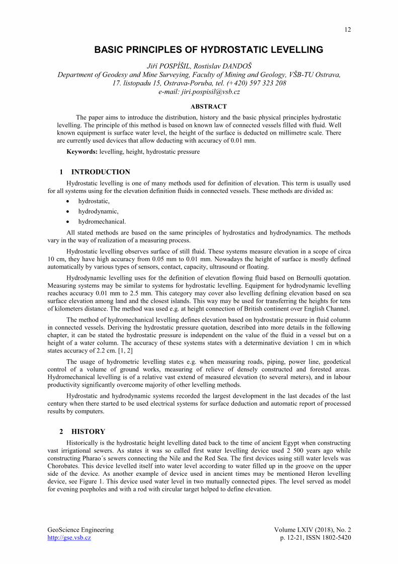
side of the device. As another example of device used in ancient times may be mentioned Heron levelling
device, see Figure 1. This device used water level in two mutually connected pipes. The level served as model
for evening peepholes and with a rod with circular target helped to define elevation.
13
GeoScience Engineering Volume LXIV (2018), No. 2
http://gse.vsb.cz p. 12-21, ISSN 1802-5420
Fig. 1. Heron´s levelling device [3]
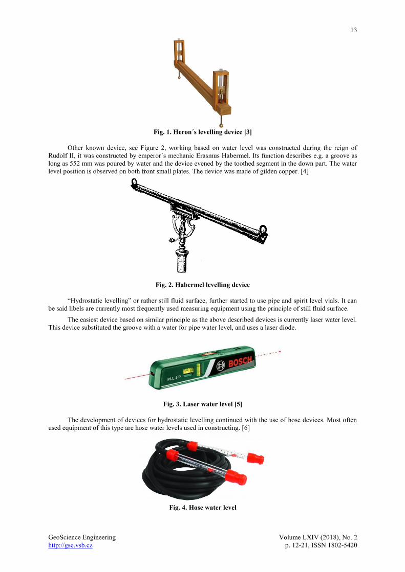
Other known device, see Figure 2, working based on water level was constructed during the reign of
Rudolf II, it was constructed by emperor´s mechanic Erasmus Habermel. Its function describes e.g. a groove as
long as 552 mm was poured by water and the device evened by the toothed segment in the down part. The water
level position is observed on both front small plates. The device was made of gilden copper. [4]
Fig. 2. Habermel levelling device
“Hydrostatic levelling” or rather still fluid surface, further started to use pipe and spirit level vials. It can
be said libels are currently most frequently used measuring equipment using the principle of still fluid surface.
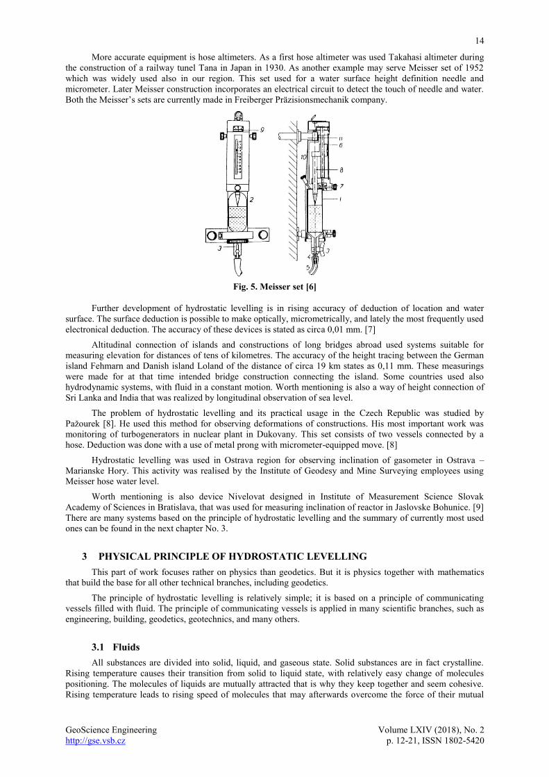
The easiest device based on similar principle as the above described devices is currently laser water level.
This device substituted the groove with a water for pipe water level, and uses a laser diode.
Fig. 3. Laser water level [5]
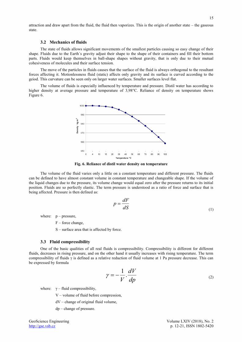
The development of devices for hydrostatic levelling continued with the use of hose devices. Most often
used equipment of this type are hose water levels used in constructing. [6]
Fig. 4. Hose water level
14
GeoScience Engineering Volume LXIV (2018), No. 2
http://gse.vsb.cz p. 12-21, ISSN 1802-5420
More accurate equipment is hose altimeters. As a first hose altimeter was used Takahasi altimeter during
the construction of a railway tunel Tana in Japan in 1930. As another example may serve Meisser set of 1952
which was widely used also in our region. This set used for a water surface height definition needle and
micrometer. Later Meisser construction incorporates an electrical circuit to detect the touch of needle and water.
Both the Meisser’s sets are currently made in Freiberger Präzisionsmechanik company.
Fig. 5. Meisser set [6]
Further development of hydrostatic levelling is in rising accuracy of deduction of location and water
surface. The surface deduction is possible to make optically, micrometrically, and lately the most frequently used
electronical deduction. The accuracy of these devices is stated as circa 0,01 mm. [7]
Altitudinal connection of islands and constructions of long bridges abroad used systems suitable for
measuring elevation for distances of tens of kilometres. The accuracy of the height tracing between the German
island Fehmarn and Danish island Loland of the distance of circa 19 km states as 0,11 mm. These measurings
were made for at that time intended bridge construction connecting the island. Some countries used also
hydrodynamic systems, with fluid in a constant motion. Worth mentioning is also a way of height connection of
Sri Lanka and India that was realized by longitudinal observation of sea level.
The problem of hydrostatic levelling and its practical usage in the Czech Republic was studied by
Pažourek [8]. He used this method for observing deformations of constructions. His most important work was
monitoring of turbogenerators in nuclear plant in Dukovany. This set consists of two vessels connected by a
hose. Deduction was done with a use of metal prong with micrometer-equipped move. [8]
Hydrostatic levelling was used in Ostrava region for observing inclination of gasometer in Ostrava –
Marianske Hory. This activity was realised by the Institute of Geodesy and Mine Surveying employees using
Meisser hose water level.
Worth mentioning is also device Nivelovat designed in Institute of Measurement Science Slovak
Academy of Sciences in Bratislava, that was used for measuring inclination of reactor in Jaslovske Bohunice. [9]
There are many systems based on the principle of hydrostatic levelling and the summary of currently most used
ones can be found in the next chapter No. 3.
3 PHYSICAL PRINCIPLE OF HYDROSTATIC LEVELLING
This part of work focuses rather on physics than geodetics. But it is physics together with mathematics
that build the base for all other technical branches, including geodetics.
The principle of hydrostatic levelling is relatively simple; it is based on a principle of communicating
vessels filled with fluid. The principle of communicating vessels is applied in many scientific branches, such as
engineering, building, geodetics, geotechnics, and many others.
3.1 Fluids
All substances are divided into solid, liquid, and gaseous state. Solid substances are in fact crystalline.
Rising temperature causes their transition from solid to liquid state, with relatively easy change of molecules
positioning. The molecules of liquids are mutually attracted that is why they keep together and seem cohesive.
Rising temperature leads to rising speed of molecules that may afterwards overcome the force of their mutual
15
GeoScience Engineering Volume LXIV (2018), No. 2
http://gse.vsb.cz p. 12-21, ISSN 1802-5420
attraction and draw apart from the fluid, the fluid then vaporizes. This is the origin of another state – the gaseous
state.
3.2 Mechanics of fluids
The state of fluids allows significant movements of the smallest particles causing so easy change of their
shape. Fluids due to the Earth´s gravity adjust their shape to the shape of their containers and fill their bottom
parts. Fluids would keep themselves in ball-shape shapes without gravity, that is only due to their mutual
cohesiveness of molecules and their surface tension.
The move of the particles in fluids causes that the surface of the fluid is always orthogonal to the resultant
forces affecting it. Motionlessness fluid (static) affects only gravity and its surface is curved according to the
geiod. This curvature can be seen only on larger water surfaces. Smaller surfaces level flat.
The volume of fluids is especially influenced by temperature and pressure. Distil water has according to
higher density at average pressure and temperature of 3,98°C. Reliance of density on temperature shows
Figure 6.
Fig. 6. Reliance of distil water density on temperature
The volume of the fluid varies only a little on a constant temperature and different pressure. The fluids
can be defined to have almost constant volume in constant temperature and changeable shape. If the volume of
the liquid changes due to the pressure, its volume change would equal zero after the pressure returns to its initial
position. Fluids are so perfectly elastic. The term pressure is understood as a ratio of force and surface that is
being affected. Pressure is then defined as:
dS
dFp
(1)
where: p – pressure,
F – force change,
S – surface area that is affected by force.
3.3 Fluid compressibility
One of the basic qualities of all real fluids is compressibility. Compressibility is different for different
fluids, decreases in rising pressure, and on the other hand it usually increases with rising temperature. The term
compressibility of fluids γ is defined as a relative reduction of fluid volume at 1 Pa pressure decrease. This can
be expressed by formula
dp
dV
V.1
(2)
where: γ – fluid compressibility,
V – volume of fluid before compression,
dV – change of original fluid volume,
dp – change of pressure.
16
GeoScience Engineering Volume LXIV (2018), No. 2
http://gse.vsb.cz p. 12-21, ISSN 1802-5420
3.4 Pascal´s law
Pascal´s law describes spread of pressure in fluids and it says according “A change in pressure at any
point in an enclosed fluid at rest is transmitted undiminished to all points in the fluid.” That means when
affected by the external pressure the hydrostatic pressure in fluid decreases equally, and the difference of
hydrostatic pressures in different height of a water column remain unchanged.
3.5 Hydrostatic pressure
Hydrostatic pressure is understood any pressure in fluid, it is caused by the weight of fluid and external
force. In case of free surface of fluid, the only external force acting on the fluid is barometric pressure. In other
horizontal level every fluid particle is acting by force caused by surrounding particles in all directions. The
pressure is so submitted and affects the sides of the vessel by perpendicular forces (perpendicular pressures), or
the surface of dived object.
The relation for hydrostatic pressure can be derived from the Newton laws of motion. When the second
law can be defined as:
dt
dvmF
(3)
where: F – force acting on object,
m – weight of object,
dv – decrease object speed,
dt – duration of force acting on object.
This formula may be applied if the weight m of the object is constant. Adding the formula the
acceleration element the object gains through the acting of force F:
dt
dva
(4)
Then we get a relation:
amF (5)
Considering the hydrostatic pressure being caused by the weight of fluid and external force, then the
weight of the fluid may be defined.
gmG
(6)
where: g – gravitational acceleration.
The weight of the fluid object in depth h can be defined as
ShVm
(7)
where: m – weight of fluid object,
V – volume of fluid object,
ρ – fluid density,
h – depth of base under the surface (height object),
S – area of fluid object base.
The previous relations then define a relation for figure of hydrostatic pressure p in depth h:
ghS
gSh
S
Gp
(8)
where: p – hydrostatic pressure.
17
GeoScience Engineering Volume LXIV (2018), No. 2
http://gse.vsb.cz p. 12-21, ISSN 1802-5420
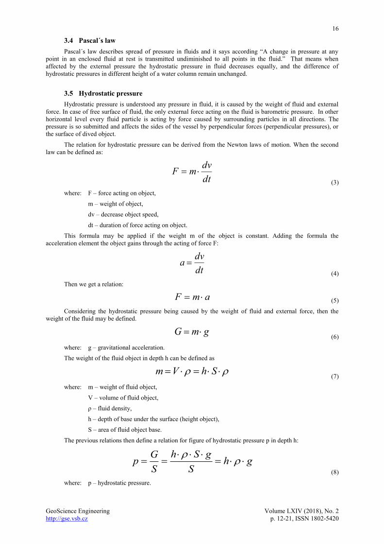
Fig. 7. Reliance of hydrostatic pressure on depth
Hydrostatic pressure caused by weight depends only on depth h under the surface, that is why it is even in
the whole horizontal level, see Figure 7. In connected vessels of a big enough diameter (not to show the surface
tension) the surface calms and the pressure evens in all levels. In case both the surfaces are affected by the same
external pressure, they are in the same horizontal level.
Some sources state as base of hydrostatic levelling the Bernoulli's equation in fluid dynamics. Using the
Bernoulli formula for quoting the figure of pressure at zero flow speed, the pressure equals hydrostatic pressure.
3.6 Surface tension
Fluids act as their surface was covered with very thin and elastic layer trying to tighten the surface of the
fluid to the smallest possible area. In case the fluid was not affected by any external forces it would be of a ball-
shaped shape, because it is the ball that has the smallest shape out of all solids of the same volume. The reason of
the surface tension is a capillary phenomenon.
This phenomenon can be demonstrated on soap water in a wire loop (bubble blower), the fluid creates
thin film and tightens so it has the smallest surface. Surface tension σ and capillary phenomena are explained by
mutual effect of attractive forces of molecules, so called cohesive forces. The result of effect of cohesive forces
is cohesive pressure. Cohesive pressure cannot be measured directly it can be estimated based on theoretical
data.
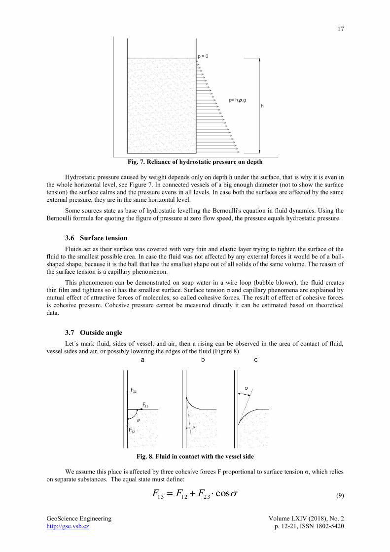
3.7 Outside angle
Let´s mark fluid, sides of vessel, and air, then a rising can be observed in the area of contact of fluid,
vessel sides and air, or possibly lowering the edges of the fluid (Figure 8).
Fig. 8. Fluid in contact with the vessel side
We assume this place is affected by three cohesive forces F proportional to surface tension σ, which relies
on separate substances. The equal state must define:
cos231213 FFF (9)

18
GeoScience Engineering Volume LXIV (2018), No. 2
http://gse.vsb.cz p. 12-21, ISSN 1802-5420
then
13
2312
13
2312cos
F
FF (10)
where: F – cohesive force,
σ – surface tension between substances,
ʋ – fluid edge angle.
ʋ angle is called edge (side) angle. If it is a case of a contact of the same three settings, the edge angle is
the same. The value of the edge angle in contact with water, glass, and air is very small, approximately 8°.
3.8 Capillary phenomena
The surface of fluid in a tight pipe (capillary) is not always flat, the above stated shows that the surface
bends. As an example, there can be used small glass plate dipped in the water, Figure 9. Its dipping causes the
same elevation as in the case of the vessel sides. When moving the small plate close enough to the vessel side,
there occurs so called capillary elevation and the water surface rises higher than the surrounding surface.
Fig. 9. Capillary phenomena
The opposite example is capillary depression. The values of elevation or depression of the surface in
capillary can be calculated out of equal cohesive forces and gravitational force of fluid in capillary. The surface
height in a capillary then equals:
gr
h..
.2
(11)
where: h – difference of surfaces,
σ – surface tension,
r – capillary radius,
ρ – fluid density,
g – gravitation acceleration.
The formula (11) shows the surface difference is inversely proportionated to the capillary radius.
3.9 Summary of physical principles
The principle of hydrostatic levelling and the construction of measuring devices is based on all stated
physical laws. It is important to realize that hydrostatic levelling observes free surface of connected vessels with
zero hydrostatic pressure. The surfaces of the vessels must be affected by even external (atmospheric) pressure
and even weight acceleration. The effect of same external pressure and weight acceleration is possible to assume
when observing small-sized objects.
The other important condition is a homogenous fluid temperature having effect on its density and its
volume afterwards. Different fluid temperature and effect on its density can be mathematically defined and the
results may be corrected. The fluid temperature should be in ideal case measured continuously along with the
19
GeoScience Engineering Volume LXIV (2018), No. 2
http://gse.vsb.cz p. 12-21, ISSN 1802-5420
whole height of the pipe between devices for their difference. The praxis measures the fluid temperature only at
certain points of the pipe bringing so a certain inaccuracy into calculations.
The accuracy of measuring may even be affected by the construction of deductive devices. The deductive
devices should be same and their measures should be chosen the way the results would not be influenced by the
capillary phenomena.
The hydrostatic levelling devices used for further distances (several kilometres) are necessary to consider
elasticity of fluid and pipe, changes of atmospheric pressure and tides. [10]
4 CURRENT HYDROSTATIC SYSTEMS
This chapter shortly describes ways of surface height registration. The next part briefly describes most
frequently used systems in the Czech Republic and the whole world. Overview of the system is brief because
currently exists of more than one hundred of hydrostatic systems
Most frequently are currently used hydrostatic systems enabling very accurate definition of moves and
deformation of observed objects. They are stationary and fully automatic systems.
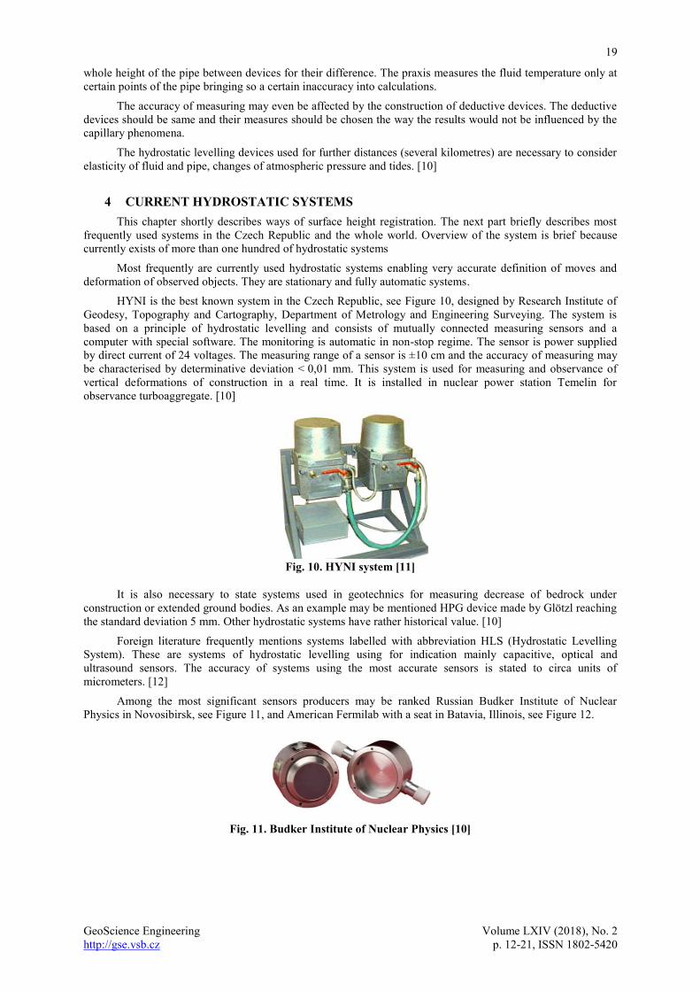
HYNI is the best known system in the Czech Republic, see Figure 10, designed by Research Institute of
Geodesy, Topography and Cartography, Department of Metrology and Engineering Surveying. The system is
based on a principle of hydrostatic levelling and consists of mutually connected measuring sensors and a
computer with special software. The monitoring is automatic in non-stop regime. The sensor is power supplied
by direct current of 24 voltages. The measuring range of a sensor is ±10 cm and the accuracy of measuring may
be characterised by determinative deviation < 0,01 mm. This system is used for measuring and observance of
vertical deformations of construction in a real time. It is installed in nuclear power station Temelin for
observance turboaggregate. [10]
Fig. 10. HYNI system [11]
It is also necessary to state systems used in geotechnics for measuring decrease of bedrock under
construction or extended ground bodies. As an example may be mentioned HPG device made by Glötzl reaching
the standard deviation 5 mm. Other hydrostatic systems have rather historical value. [10]
Foreign literature frequently mentions systems labelled with abbreviation HLS (Hydrostatic Levelling
System). These are systems of hydrostatic levelling using for indication mainly capacitive, optical and
ultrasound sensors. The accuracy of systems using the most accurate sensors is stated to circa units of
micrometers. [12]
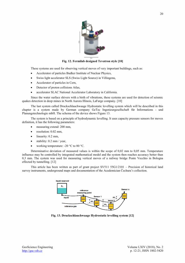
Among the most significant sensors producers may be ranked Russian Budker Institute of Nuclear
Physics in Novosibirsk, see Figure 11, and American Fermilab with a seat in Batavia, Illinois, see Figure 12.
Fig. 11. Budker Institute of Nuclear Physics [10]
20
GeoScience Engineering Volume LXIV (2018), No. 2
http://gse.vsb.cz p. 12-21, ISSN 1802-5420
Fig. 12. Fermilab designed Tevatron style [10]
These systems are used for observing vertical moves of very important buildings, such as:
Accelerator of particles Budker Institute of Nuclear Physics,
Swiss light accelerator SLS (Swiss Light Source) in Villingenu,
Accelerator of particles in Cern,
Detector of proton collisions Atlas,
accelerator SLAC National Accelerator Laboratory in California.
Since the water surface shivers with a birth of vibrations, these systems are used for detection of seismic
quakes detection in deep mines in North Aurora Illinois, LaFarge company. [10]
The last system called Druckschlauchwaage Hydrostatic levelling system which will be described in this
chapter is a system made by German company GeTec Ingenieurgesellschaft für Informations - und
Planungstechnologie mbH. The schema of the device shows Figure 13.
The system is based on a principle of hydrodynamic levelling. It uses capacity pressure sensors for moves
definition, it has the following parameters:
measuring extend: 200 mm,
resolution: 0.02 mm,
linearity: 0.2 mm,
stability: 0.2 mm / year,
working temperature: -20 °C to 80 °C.
Determinative deviation of measured values is within the scope of 0,02 mm to 0,05 mm. Temperature
influence may be controlled by integrated mathematical model and the system then reaches accuracy better than
0,3 mm. The system was used for measuring vertical moves of a railway bridge Ponte Vecchio in Bologna
effected by tunnelling. [12]
This article has been written as part of grant project SV511 55G1/2101 – Precision of historical land
survey instruments, underground maps and documentation of the Academician Čechura’s collection.
Fig. 13. Druckschlauchwaage Hydrostatic levelling system [12]
21
GeoScience Engineering Volume LXIV (2018), No. 2
http://gse.vsb.cz p. 12-21, ISSN 1802-5420
5 SUMMARY
Finally, it should be mentioned that the current use of hydrostatic levelling systems is very limited in the
Czech Republic. From a geodetic aspect it is only a HYNI system. Wider use of these systems is found in
geotechnics where they have become a commonly used geotechnical monitoring method.
This fact may be due to a certain lack of knowledge about this issue because hydrostatic levelling is mentioned
very briefly in most textbooks and usually only the principle of connected vessels is mentioned. In the best case,
the Bernoulli equation is given and briefly mentions the use and accuracy of the method. In most expert
textbooks, we do not know anything about the principles of hydrodynamic and hydromechanical levelling even
though this height measurement method is one of the oldest and today has relatively large potential in terms of
accuracy and speed of the measurement.
REFERENCES
[1] LECHNER, J. On the Question of Measuring Vertical Movements Using the Principle of Hydrostatic
Levelling. Geodetický a kartografický obzor. 1990. 36/78, vol. 12, p. 304-310. Available from:
http://archivnimapy.cuzk.cz/zemvest/texty/Rok1990.pdf.
[2] VASJUTINSKIJ, I. J. Gidrostatičeskoje nivelirovanije. Moscow: Nedra 1984.
[3] The dioptra of Heron. Kotsanas Museum of the Ancient Greek Technology. [online] Ilia [cited 2017-
12-20] Available from: http://kotsanas.com/gb/exh.php?exhibit=1301002.
[4] STAŇKOVÁ, H. and P. ČERNOTA. A principle of forming and developing geodetic bases in the
Czech Republic, Geodesy and Cartography. 2010, 36(03) pp. 103–112. ISSN: 1392-1541.
[5] ROBERT BOSCH GmbH, Power tools Division, PLL 1 P Available from: https://www.bosch-do-
it.de/de/de/bosch-elektrowerkzeuge/werkzeuge/pll-1-p-3165140710862-199931.jsp#tab_technical.
[6] JADVIŠČOK, P., R. DANDOŠ and T. JIROUŠEK. Measurement of verticality construction of
bushings for laboratory construction materials. Geodesy and Cartography. 2014. 40(04) pp. 171–174.
ISSN: 1392-1541.
[7] SLADKOVÁ, D. Měření výšek (Measuring heights). [online] VŠB-TUO 2002. [cited 2017-12-20]
Available from: http://igdm.vsb.cz/igdm/materialy/Mereni_vysek.pdf.
[8] PAŽOUREK, J. Závislost výsledků hydrostatické nivelace na rozdílné teplotě vody v přístrojích.
Geodetický a kartografický obzor. 1982, 28/70, vol. 10, p. 277-281.
[9] MICHALČÁK, O., Ľ. ONDRIŠ and Š. MANKOVICKÝ. Nové přístroje na presné merianie náklonu
objektou (New apparati for precise measurements of tilt). Geodetický a kartografický obzor. 1993,
39/81, vol. 11, p. 234-238.
[10] VOLK, J. T. HLS systems at Fermilab and DUSEL. [online] Fermi National Accelerator Laboratory,
Fermilab Computing Sector [cited 2017-12-20].
Available from: http://indico.cern.ch/event/54777/session/1/contribution/15/attachments/978796/13910
86/FERMI.pdf.
[11] VÚGTK. Research Institute of Geodesy, Topography and Cartography, v.v.i. Research department of
Metrology and Engineering Geodesy [online]. [cited 2017-12-20] Available from:
http://www.vugtk.cz/odd25/ind25.html.
[12] JAKOBS, M., C. KUMMERER and V. MARCHIONNI. The application of a hydrostatic levelling
system under extreme temperature conditions for the control of a protective measure for the tunelling
under a railway bridge in Italy [online]. Fermi National Accelerator Laboratory, Fermilab Computing
Sector. GeTec Ingenieurgesellschaft für Informations- und Planungstechnologie mbH. [cited 2017-12-
20] Available from: http://www.getec-ac.de/download/en/pdf/GeTec06-12E.pdf