Embed Size (px)
Citation preview
Feasibility Study Project for the JCM (2015FY)
(Basic Study on Support for promoting
JCM-related policies and measures
in the Islamic Republic of Iran)
March 2016
Mizuho Research Institute, Ltd.

[Table of Contents]
1.Background and purpose of this project .......................................................................................... 1
2.Identification of the project candidates suitable for the JCM scheme .............................................. 2
2.1 Technological requirement and industrial trends in Iran .............................................................. 2
2.2 Possibility of contribution of Japanese companies ....................................................................... 4
2.3 Identification of high priority types ............................................................................................. 4
3.Study of the business opportunity and financial environment .......................................................... 6
3.1 Study of the business opportunity ................................................................................................ 6
3.2 Study of the financial environment ............................................................................................ 15
4.Draft of JCM methodology and estimate of GHG emission reductions ......................................... 18
4.1 Flare Gas Recovery ................................................................................................................... 18
4.2 Conversion of the Gas-Fired Power Plant from Simple to Combined Cycle .............................. 21
4.3 Low-loss transmission / distribution line ................................................................................... 25
5.Analysis of the Benefit of both countries ....................................................................................... 30
5.1 Flare Gas Recovery ................................................................................................................... 30
5.2 Conversion of the Gas-Fired Power Plant from Simple to Combined Cycle .............................. 31
5.3 Low-loss transmission / distribution line ................................................................................... 32
6.Steps towards the JCM Projects .................................................................................................... 33


1
1.Background and purpose of this project
In the Islamic Republic of Iran, energy consumption is expected to increase in the near
future. Expansion of power generation capacity by introducing high efficiency power
system and renewable energy is required. JCM scheme making use of Japanese energy
efficiency and low-carbon technologies will be one of the promising alternatives for the
solution.
In this project, we will identify the high priority industry sectors for JCM projects
making use of low-carbon technologies from the Iranian economic, industrial and policy
perspectives and will promote an understanding of Iranian government about JCM
scheme in conducting studies on the necessary actions (e.g. policy recommendations,
financial support) for JCM projects and the rough estimation of expected GHG emission
reductions.
2
2.Identification of the project candidates suitable for the JCM scheme
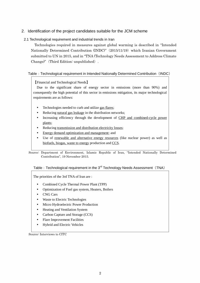
2.1 Technological requirement and industrial trends in Iran
Technologies required in measures against global warming is described in “Intended
Nationally Determined Contribution (INDC)”(2015/11/19)which Iranian Government
submitted to UN in 2015, and in “TNA (Technology Needs Assessment to Address Climate
Change)”(Third Edition: unpublished).
Table:Technological requirement in Intended Nationally Determined Contribution(INDC)
【Financial and Technological Needs】
Due to the significant share of energy sector in emissions (more than 90%) and
consequently the high potential of this sector in emissions mitigation, its major technological
requirements are as follows:
Technologies needed to curb and utilize gas flares;
Reducing natural gas leakage in the distribution networks;
Increasing efficiency through the development of CHP and combined-cycle power
plants;
Reducing transmission and distribution electricity losses;
Energy demand optimization and management; and
Use of renewable and alternative energy resources (like nuclear power) as well as
biofuels, biogas, waste to energy production and CCS.
Source: Department of Environment, Islamic Republic of Iran, “Intended Nationally Determined
Contribution”, 19 November 2015.
Table:Technological requirement in the 3rd
Technology Needs Assessment(TNA)
The priorities of the 3rd TNA of Iran are :
Combined Cycle Thermal Power Plant (TPP)
Optimization of Fuel gas system, Heaters, Boilers
CNG Cars
Waste to Electric Technologies
Micro Hydroelectric Power Production
Heating and Ventilation System
Carbon Capture and Storage (CCS)
Flare Improvement Facilities
Hybrid and Electric Vehicles
Source: Interviews to CITC

3
According to the technology requirements in INDC and TNA, Iran has the needs for
energy savings in the field of oil and natural gas, energy conservation, energy
transmission, energy demand and CCS. These fields largely cover the industrial fields
whose potentials for energy savings and CO2 reductions are high.
Table:Technology requirements in INDC and TNA
Sector Project Type INDC (2015) 3rd
TNA (2016)
1 Oil & Gas Gas flare Curb and utilization Improvement
2 Gas leakage Reduction in the
distribution networks -
3 Energy
conversion
Thermal power CHP
Combined Cycle
Combined Cycle
Optimization of Fuel
gas system
4 Heater / Boiler -
Optimization of
Heaters and Boilers
5 Renewable / alternative
energy
Biofuels
Biogas
Waste to Energy
Nuclear
Waste to Energy
Micro Hydropower
6 Energy
transmission
Electricity loss Reduction in the
transmission and
distribution
-
7 Energy
demand
Demand optimization
and management
Demand optimization
and management
Heating and
Ventilation System
8 Transportation
-
CNG Cars
Hybrid and Electric
Vehicles
9 CCS CCS CCS
Source: INDC and interviews to CITC.
In addition, it was found that the organizations and companies were actually involved
in the energy projects such as power generation including renewable energy, waste heat
recovery system, fuel conversion to natural gas and biogas recovery. These projects are
generally consistent with the fields where CDM projects have been conducted in Iran.
4
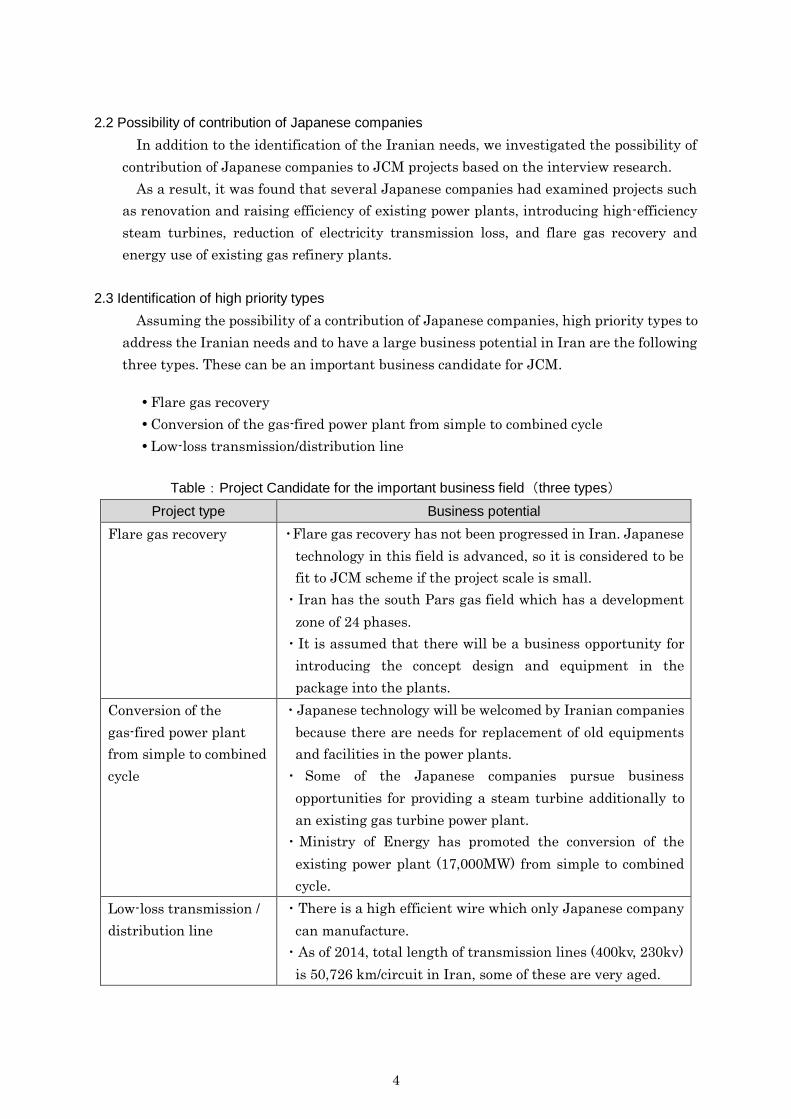
2.2 Possibility of contribution of Japanese companies
In addition to the identification of the Iranian needs, we investigated the possibility of
contribution of Japanese companies to JCM projects based on the interview research.
As a result, it was found that several Japanese companies had examined projects such
as renovation and raising efficiency of existing power plants, introducing high-efficiency
steam turbines, reduction of electricity transmission loss, and flare gas recovery and
energy use of existing gas refinery plants.
2.3 Identification of high priority types
Assuming the possibility of a contribution of Japanese companies, high priority types to
address the Iranian needs and to have a large business potential in Iran are the following
three types. These can be an important business candidate for JCM.
Flare gas recovery
Conversion of the gas-fired power plant from simple to combined cycle
Low-loss transmission/distribution line
Table:Project Candidate for the important business field(three types)
Project type Business potential
Flare gas recovery ・Flare gas recovery has not been progressed in Iran. Japanese
technology in this field is advanced, so it is considered to be
fit to JCM scheme if the project scale is small.
・Iran has the south Pars gas field which has a development
zone of 24 phases.
・It is assumed that there will be a business opportunity for
introducing the concept design and equipment in the
package into the plants.
Conversion of the
gas-fired power plant
from simple to combined
cycle
・Japanese technology will be welcomed by Iranian companies
because there are needs for replacement of old equipments
and facilities in the power plants.
・ Some of the Japanese companies pursue business
opportunities for providing a steam turbine additionally to
an existing gas turbine power plant.
・Ministry of Energy has promoted the conversion of the
existing power plant (17,000MW) from simple to combined
cycle.
Low-loss transmission /
distribution line
・There is a high efficient wire which only Japanese company
can manufacture.
・As of 2014, total length of transmission lines (400kv, 230kv)
is 50,726 km/circuit in Iran, some of these are very aged.

5
In addition to these three types, waste to energy, waste heat recovery in cement
factories, waste heat recovery in paper mills, and geothermal power plants, and
small-scale CHP can be a project candidate for JCM considering Iranian needs and
Japanese technologies.
Table:Other candidates for JCM
Project type Views of Iranian organization and Japanese companies
Waste to Energy ・A large amount of waste is generated in the large cities in
northern area. Introduction of an efficient incineration
system contributes to reduce CO2 emissions and solve
the problem of waste management.
・In Teheran, 7,000t/day waste is generated.
Waste heat recovery in
cement factory
・A high priority fields of introducing the heat recovery
system are cement, steel and chemical.
・There are more then 50 factories which are owned by
private sector.
Waste heat recovery in
paper mill
・Electricity is generated by a boiler in paper mills. The
introduction of a high efficiency boiler made by Japanese
high technologies can be a JCM project candidate.
Geothermal power plant ・There is a geothermal power plant project at the foot of
Mt. Savalan.
Small-scale CHP ・ The project to introduce 2~3 MW CHP per one
government facility can be a JCM project candidate. The
total potential of introducing small-scale CHP is 800MW.
In the following sections, we investigate the three project types in detail, which we
selected as important business fields for JCM scheme.
6
3.Study of the business opportunity and financial environment
3.1 Study of the business opportunity
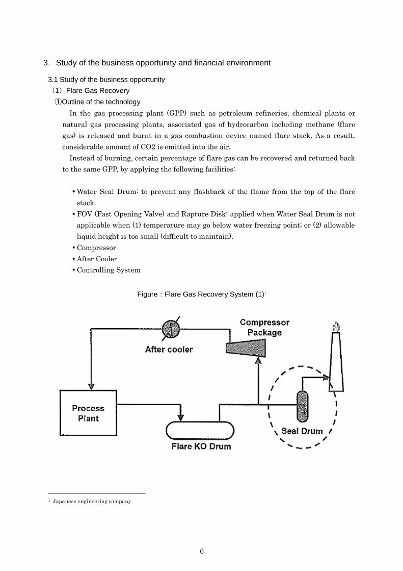
(1)Flare Gas Recovery
①Outline of the technology
In the gas processing plant (GPP) such as petroleum refineries, chemical plants or
natural gas processing plants, associated gas of hydrocarbon including methane (flare
gas) is released and burnt in a gas combustion device named flare stack. As a result,
considerable amount of CO2 is emitted into the air.
Instead of burning, certain percentage of flare gas can be recovered and returned back
to the same GPP, by applying the following facilities:
Water Seal Drum: to prevent any flashback of the flame from the top of the flare
stack.
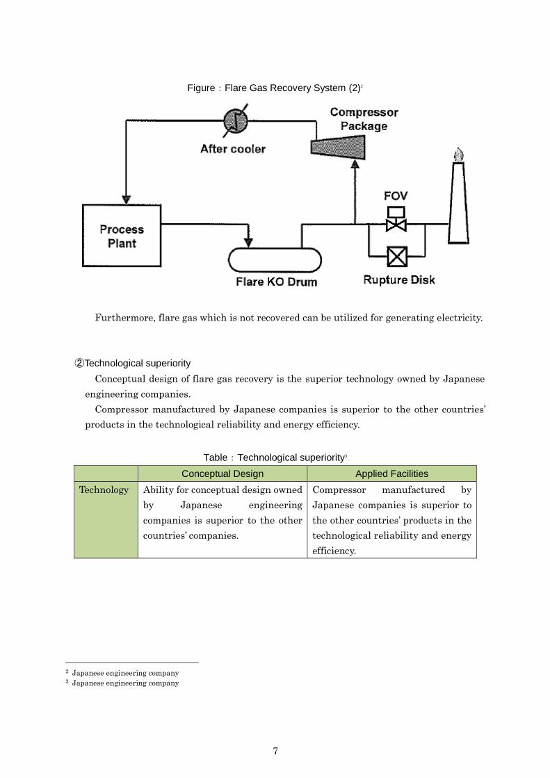
FOV (Fast Opening Valve) and Rapture Disk: applied when Water Seal Drum is not
applicable when (1) temperature may go below water freezing point; or (2) allowable
liquid height is too small (difficult to maintain).
Compressor
After Cooler
Controlling System
Figure:Flare Gas Recovery System (1)1
1 Japanese engineering company
7
Figure:Flare Gas Recovery System (2)2
Furthermore, flare gas which is not recovered can be utilized for generating electricity.
②Technological superiority
Conceptual design of flare gas recovery is the superior technology owned by Japanese
engineering companies.
Compressor manufactured by Japanese companies is superior to the other countries’
products in the technological reliability and energy efficiency.
Table:Technological superiority3
Conceptual Design Applied Facilities
Technology Ability for conceptual design owned
by Japanese engineering
companies is superior to the other
countries’ companies.
Compressor manufactured by
Japanese companies is superior to
the other countries’ products in the
technological reliability and energy
efficiency.
2 Japanese engineering company 3 Japanese engineering company
8
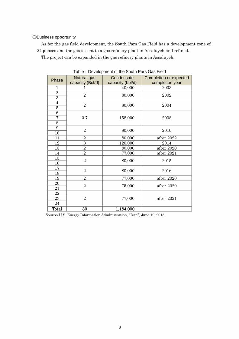
③Business opportunity
As for the gas field development, the South Pars Gas Field has a development zone of
24 phases and the gas is sent to a gas refinery plant in Assaluyeh and refined.
The project can be expanded in the gas refinery plants in Assaluyeh.
Table:Development of the South Pars Gas Field
Phase Natural gas
capacity (Bcf/d) Condensate
capacity (bbl/d) Completion or expected
completion year
1 1 40,000 2003
2 2 80,000 2002
3
4 2 80,000 2004
5
6
3.7 158,000 2008 7
8
9 2 80,000 2010
10
11 2 80,000 after 2022
12 3 120,000 2014
13 2 80,000 after 2020
14 2 77,000 after 2021
15 2 80,000 2015
16
17 2 80,000 2016
18
19 2 77,000 after 2020
20 2 75,000 after 2020
21
22
2 77,000 after 2021 23
24
Total 30 1,184,000
Source: U.S. Energy Information Administration, “Iran”, June 19, 2015.
9
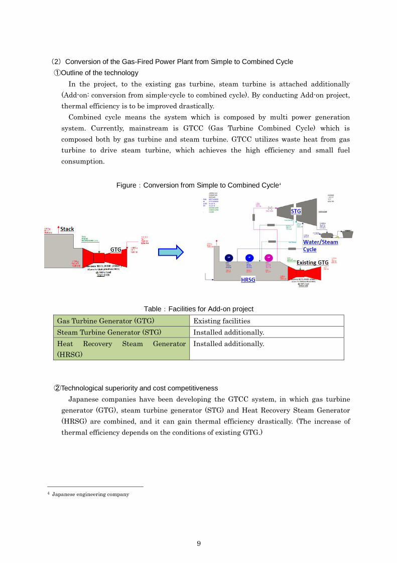
(2)Conversion of the Gas-Fired Power Plant from Simple to Combined Cycle
①Outline of the technology
In the project, to the existing gas turbine, steam turbine is attached additionally
(Add-on: conversion from simple-cycle to combined cycle). By conducting Add-on project,
thermal efficiency is to be improved drastically.
Combined cycle means the system which is composed by multi power generation
system. Currently, mainstream is GTCC (Gas Turbine Combined Cycle) which is
composed both by gas turbine and steam turbine. GTCC utilizes waste heat from gas
turbine to drive steam turbine, which achieves the high efficiency and small fuel
consumption.
Figure:Conversion from Simple to Combined Cycle4
Table:Facilities for Add-on project
Gas Turbine Generator (GTG) Existing facilities
Steam Turbine Generator (STG) Installed additionally.
Heat Recovery Steam Generator
(HRSG)
Installed additionally.
②Technological superiority and cost competitiveness
Japanese companies have been developing the GTCC system, in which gas turbine
generator (GTG), steam turbine generator (STG) and Heat Recovery Steam Generator
(HRSG) are combined, and it can gain thermal efficiency drastically. (The increase of
thermal efficiency depends on the conditions of existing GTG.)
4 Japanese engineering company

10
Table:Technological superiority and initial cost5
Technological
Superiority
Matching technology of the facility components to achieve
high thermal efficiency.
Initial cost Approximately 10 billion JPY for the Add-on to the existing
gas-fired power plant (simple-cycle) that has capacity of
30-50 MW.
③Business opportunity
Based on our interview research with Iranian organisations, Iranian government
wants to proceed conversion of existing simple-cycle gas-fired power plants (total capacity
17,000MW) to combined-cycle ones as soon as possible.
It is considered that there may be business opportunities in these conversion projects.
5 Japanese engineering company

11
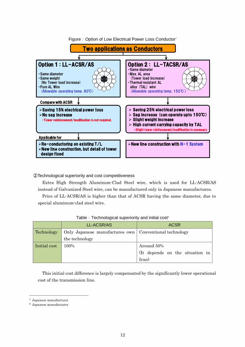
(3)Low-loss transmission / distribution line
①Outline of the technology
Low-loss transmission / distribution line is called as LL-ACSR/AS: Low Electrical
Power Loss Aluminum Conductors, Aluminum-Clad Steel Reinforced, which have lower
transmission loss compared to ACSR by increasing the area of conductive component
(hereinafter called “Low Loss Conductor”).
By installing that type of energy-efficient technology, transmission losses can be
reduced by roughly 10-25% compared with conventional conductors.
Option 1: Reduce power loss by roughly 10-15 %
Option 2: Reduce power loss by roughly 20-25 %
Figure:Cross sectional view and Key component6
6 Japanese manufacturer
Cross sectional view
Conventional Conductor (ACSR)
Low Electrical Power Loss Conductor
Aluminumwire
GalvanizedSteel wire
Aluminum Clad Steel wire
OPTION 1
Thermal ResistantAluminum Alloy wire
OPTION 2
Key component for Low Electrical Power Loss ConductorAluminum Clad Steel Wire
Aluminum Clad Steel wire・ Conductivity : 14% IACS・ Tensile Strength : 1770MPa
Aluminum
Steel
12
Figure:Option of Low Electrical Power Loss Conductor7
②Technological superiority and cost competitiveness
Extra High Strength Aluminum-Clad Steel wire, which is used for LL-ACSR/AS
instead of Galvanized Steel wire, can be manufactured only in Japanese manufactures.
Price of LL-ACSR/AS is higher than that of ACSR having the same diameter, due to
special aluminum-clad steel wire.
Table:Technological superiority and initial cost8
LL-ACSR/AS ACSR
Technology Only Japanese manufactures own
the technology
Conventional technology
Initial cost 100%
Around 50%
(It depends on the situation in
Iran)
This initial cost difference is largely compensated by the significantly lower operational
cost of the transmission line.
7 Japanese manufacturer 8 Japanese manufacturer
Two applications as Conductors
Saving 15% electrical power lossNo sag increase・Tower reinforcement/modification is not required.
Saving 25% electrical power loss Sag increase (can operate upto 150℃) Slight weight increase High current carrying capacity by TAL
・Slight tower reinforcement/modification is necessary
Option 1 : LL-ACSR/AS
・Same diameter ・Same weight(No Tower load increase)
・Pure AL Wire(Allowable operating temp. 80℃)
Option 2 : LL-TACSR/AS・Same diameter・Max. AL area(Tower load increase)
・Thermal resistant AL alloy (TAL) wire (Allowable operating temp. 150℃)
Re-conductoring on existing T/LNew line construction, but detail of tower
design fixed
New line construction with N-1 System
Applicable for
Compare with ACSR

13
③Business opportunity
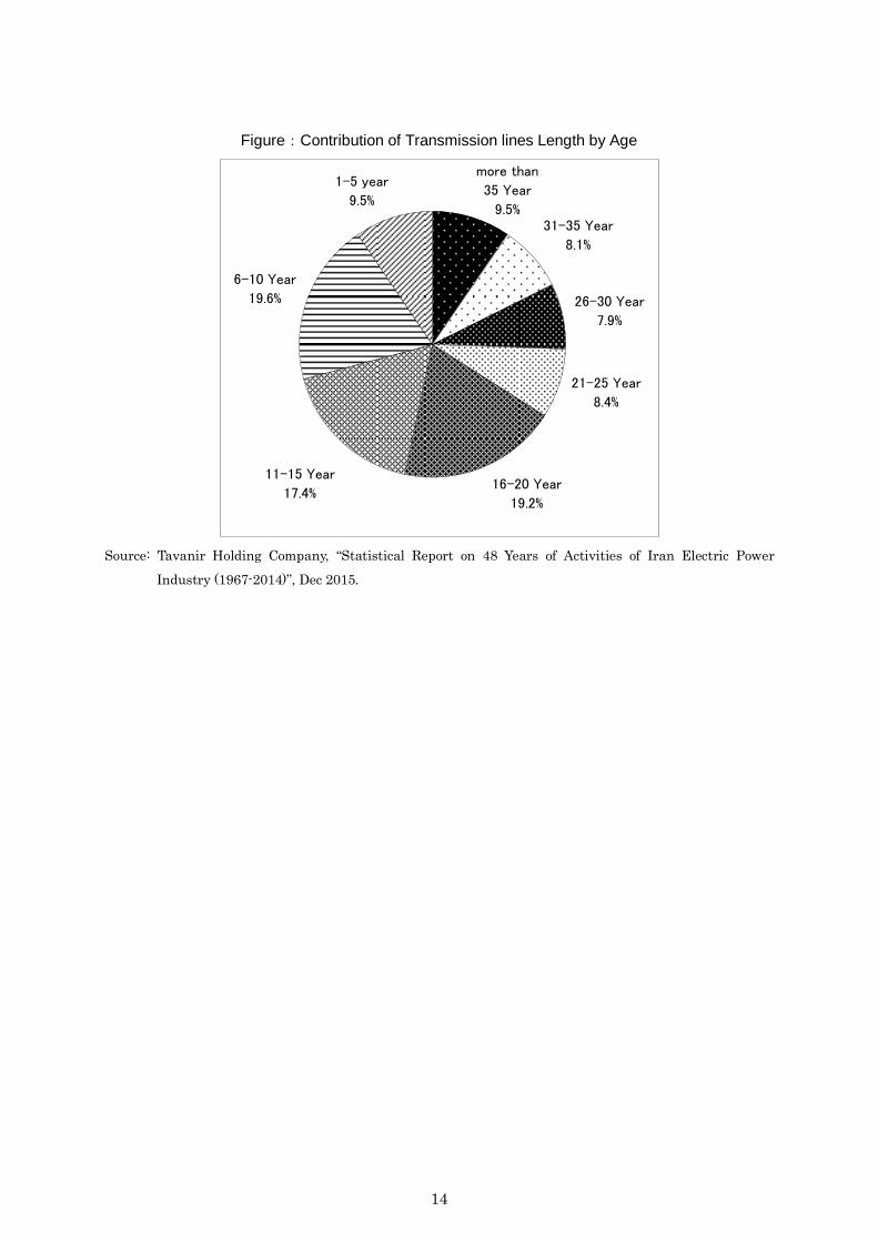
As of 2014, a total length of transmission lines (400kv, 230kv) is 50,726km / circuit,
around one-fourth of which has over 25 years of age. There may be business opportunities
in replacing these lines.
Figure:Transmission Lines Length (by age)
Source: Tavanir Holding Company, “Statistical Report on 48 Years of Activities of Iran Electric Power
Industry (1967-2014)”, Dec 2015.
1,251
1,919
1,514
481
3,991
2,692
5,590
2,245
3,565
2,201
2,738
3,767
5,757 6,123
4,336
2,557
0
1,000
2,000
3,000
4,000
5,000
6,000
7,000
<35 31~35 26~30 21~25 16~20 11~15 6~10 1~5
400kv 230kv
(Age)
(Km Circuit)
14
Figure:Contribution of Transmission lines Length by Age
Source: Tavanir Holding Company, “Statistical Report on 48 Years of Activities of Iran Electric Power
Industry (1967-2014)”, Dec 2015.
more than
35 Year
9.5%31-35 Year
8.1%
26-30 Year
7.9%
21-25 Year
8.4%
16-20 Year
19.2%
11-15 Year
17.4%
6-10 Year
19.6%
1-5 year
9.5%
15
3.2 Study of the financial environment
(1) Foreign Investment Protection and Incentive Measures
Foreign Investment Promotion and Protection Act (FIPPA) stipulates foreign
investment under FIPPA shall equally enjoy all rights, protections, and facilities
available to local investments. Under FIPPA, there is no limitation on foreign ownership
and no minimum capital regulation.
As for overseas remittance, FIPPA stipulates that the principal of the foreign capital
and profits therefrom, or the balance of capital remaining in the country, after fulfillment
of all obligations an payment of legal dues and upon the approval of the Foreign
Investment Board (hereinafter “the Board”) and confirmation by the Minister of
Economic Affair and Finance, shall be transferable abroad subject to a three-month prior
notice submitted to the Board.
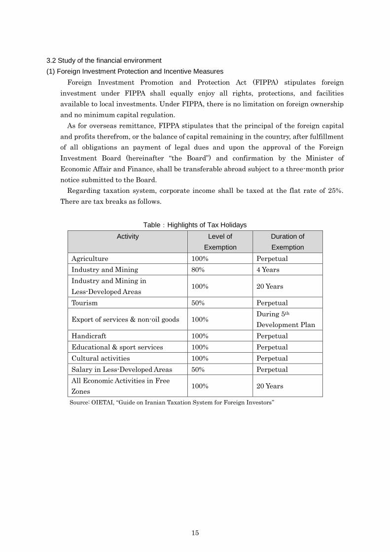
Regarding taxation system, corporate income shall be taxed at the flat rate of 25%.
There are tax breaks as follows.
Table:Highlights of Tax Holidays
Activity Level of
Exemption
Duration of
Exemption
Agriculture 100% Perpetual
Industry and Mining 80% 4 Years
Industry and Mining in
Less-Developed Areas 100% 20 Years
Tourism 50% Perpetual
Export of services & non-oil goods 100% During 5th
Development Plan
Handicraft 100% Perpetual
Educational & sport services 100% Perpetual
Cultural activities 100% Perpetual
Salary in Less-Developed Areas 50% Perpetual
All Economic Activities in Free
Zones 100% 20 Years
Source: OIETAI, “Guide on Iranian Taxation System for Foreign Investors”
16
(2) Bilateral Investment Agreement between Japan and Iran
The Agreement between Japan and the Islamic Republic of Iran on Reciprocal
Promotion and Protection of Investment (the Japan - Iran Investment Agreement) was
signed on 5th of February in 2016.
The Agreement aims at further protection and promotion of investment between Japan
and Iran. It stipulates the treatments accorded to investment activities and investments
when an investor (an enterprise etc.) of a Contracting Party invests in the other
Contracting Party, such as national treatment, most-favoured-nation treatment, fair and
equitable treatment, observance of undertaking, prohibition to impose or enforce special
requirements including export requirement, conditions for expropriation and
compensation, free transfers requirements and procedures for dispute settlements.
It is expected that this Agreement, which improves legal stability of investment, will
contribute to promotion of the reciprocal investment between the two countries.
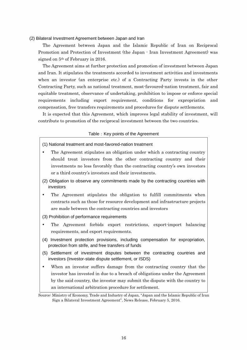
Table:Key points of the Agreement
(1) National treatment and most-favored-nation treatment
The Agreement stipulates an obligation under which a contracting country
should treat investors from the other contracting country and their
investments no less favorably than the contracting country’s own investors
or a third country’s investors and their investments.
(2) Obligation to observe any commitments made by the contracting countries with
investors
The Agreement stipulates the obligation to fulfill commitments when
contracts such as those for resource development and infrastructure projects
are made between the contracting countries and investors
(3) Prohibition of performance requirements
The Agreement forbids export restrictions, export-import balancing
requirements, and export requirements.
(4) Investment protection provisions, including compensation for expropriation,
protection from strife, and free transfers of funds
(5) Settlement of investment disputes between the contracting countries and
investors (Investor-state dispute settlement, or ISDS)
When an investor suffers damage from the contracting country that the
investor has invested in due to a breach of obligations under the Agreement
by the said country, the investor may submit the dispute with the country to
an international arbitration procedure for settlement.
Source: Ministry of Economy, Trade and Industry of Japan, “Japan and the Islamic Republic of Iran
Sign a Bilateral Investment Agreement”, News Release, February 5, 2016.

17
(3)Iranian Banking Sector
There are banks and credit Institutions such as Commercial Government-Owned
Banks, Specialized Government-Owned Banks and Non-Government-Owned Banks in
Iran. Large and major banks are Commercial Government-Owned Banks.
From the view point of obtaining finance for the JCM projects, it should be noted that
banks’ lending rates for transaction contracts are over 20% and the ratio of
Non-Performing Loan (NPL) to gross loan are high, particularly for private banks
(non-government-owned banks) in Iran.
(4) Establishment of a Financing Facility and Iran’s provision of sovereign guarantee
On February 5, 2016, Minister of Economy, Trade and Industry of Japan, signed a
memorandum of cooperation concerning establishment of a financing facility and
provision of sovereign guarantees for this facility by the government of the Islamic
Republic of Iran (hereinafter “Iran”) with Minister of Economic Affairs and Finance of
Iran, Chairman and CEO of Nippon Export and Investment Insurance (NEXI), and
Executive Managing Director and COO of Japan Bank for International Cooperation
(JBIC).
This memorandum of cooperation aims to provide financial cooperation, which will be
provided to the projects with Japanese involvement in Iran. Through this facility, both
countries will contribute to the development of Iran and the promotion of business
activities conducted by Japanese companies in Iran.
Table:Key points in the memorandum of cooperation
(1) JBIC and NEXI will establish a financing facility, up to JPY equivalent to USD
10 billion, which will be provided to projects with Japanese involvement in Iran.
(2) Ministry of Economic Affairs and Finance of Iran will provide sovereign
guarantee for the financing facility.
(3) The Trade and Investment Working Group under the Japan-Iran Cooperation
Council (bilateral governmental dialogue framework) will recommend specific
projects for this facility as necessary.
(4) The terms and conditions of each financing will be subject to satisfactory result
of due diligence for each project and credit assessment by JBIC and NEXI.
(5) Japan and Iran will endeavor to facilitate and implement projects which
contribute to the enhancement of the economic relationship between the two
countries.
Source: Ministry of Economy, Trade and Industry of Japan, ”Signing of a Memorandum of Cooperation
with Iran concerning Establishment of a Financing Facility and Iran’s provision of sovereign
guarantee”, News Release. , February 5, 2016.
18
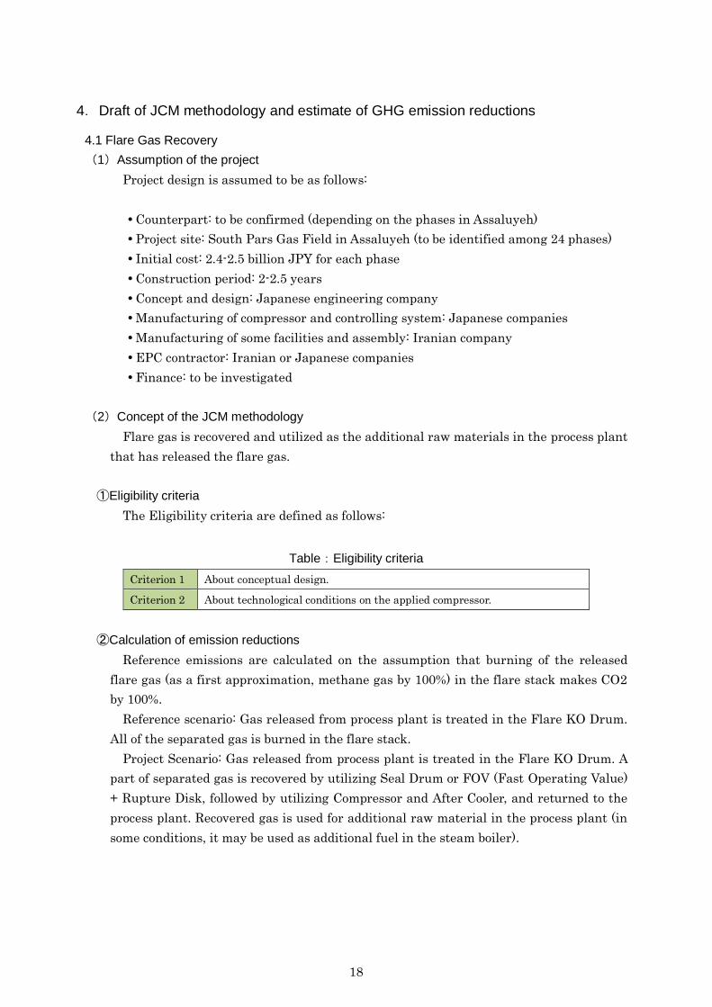
4.Draft of JCM methodology and estimate of GHG emission reductions
4.1 Flare Gas Recovery
(1)Assumption of the project
Project design is assumed to be as follows:
Counterpart: to be confirmed (depending on the phases in Assaluyeh)
Project site: South Pars Gas Field in Assaluyeh (to be identified among 24 phases)
Initial cost: 2.4-2.5 billion JPY for each phase
Construction period: 2-2.5 years
Concept and design: Japanese engineering company
Manufacturing of compressor and controlling system: Japanese companies
Manufacturing of some facilities and assembly: Iranian company
EPC contractor: Iranian or Japanese companies
Finance: to be investigated
(2)Concept of the JCM methodology
Flare gas is recovered and utilized as the additional raw materials in the process plant
that has released the flare gas.
①Eligibility criteria
The Eligibility criteria are defined as follows:
Table:Eligibility criteria
Criterion 1 About conceptual design.
Criterion 2 About technological conditions on the applied compressor.
②Calculation of emission reductions
Reference emissions are calculated on the assumption that burning of the released
flare gas (as a first approximation, methane gas by 100%) in the flare stack makes CO2
by 100%.
Reference scenario: Gas released from process plant is treated in the Flare KO Drum.
All of the separated gas is burned in the flare stack.
Project Scenario: Gas released from process plant is treated in the Flare KO Drum. A
part of separated gas is recovered by utilizing Seal Drum or FOV (Fast Operating Value)
+ Rupture Disk, followed by utilizing Compressor and After Cooler, and returned to the
process plant. Recovered gas is used for additional raw material in the process plant (in
some conditions, it may be used as additional fuel in the steam boiler).

19
③Conservativeness
Recovered gas that is returned to the process plant is used as the additional raw
material (or additional fuel) that leads to reduce consumption of raw material (or fuel).
However, for conservativeness, it is not accounted in the GHG reduction.
(3)GHG reductions
①Reference emissions
Reference emissions are calculated by the following equation:
CH4) of(weight 16
CO2) of(weight 44FGRE yy
Where
REy = Reference emission in year y [tCO2/y]
FGy = Amount of gas released from process plant followed by separation in
the Flare KO Drum in year y [t/y]
■Rough calculation
REy = 40 [t/h] * 24 * 365 * (44/16)
= 964 [ktCO2/y]
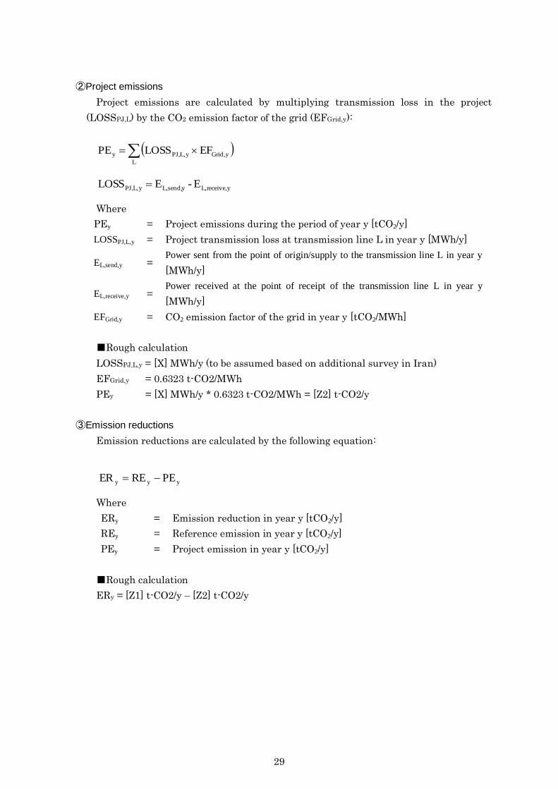
②Project emissions
Project emissions are calculated by the following equation:
yyyyy EFELRR1CH4) of(weight 16
CO2) of(weight 44FGPE
Where
PEy = Project emission in year y [tCO2/y]
FGy = Amount of gas released from process plant followed by separation in
the Flare KO Drum in year y [t/y]
RRy = Recovered Ratio of the flare gas in year y [%]
ELy = Electricity consumption applied for the recovery and usage of the
flare gas in year y [MWh/y]
EFy = Grid Emission Factor in year of y [tCO2/MWh]
■Rough calculation
REy = 40 [t/h] * 24 * 365 * (44/16) * (1-75%) + (***)
= 241 [ktCO2/y]
(Now emissions related to electricity consumption is not included.)

20
③Emission reductions
Emission reductions are calculated by the following equation:
yyy PEREER
Where
ERy = Emission reduction in year y [tCO2/y]
REy = Reference emission in year y [tCO2/y]
PEy = Project emission in year y [tCO2/y]
■Rough calculation
ERy = 964 kt-CO2/y – 241 kt-CO2/y = 723 kt-CO2/y
21
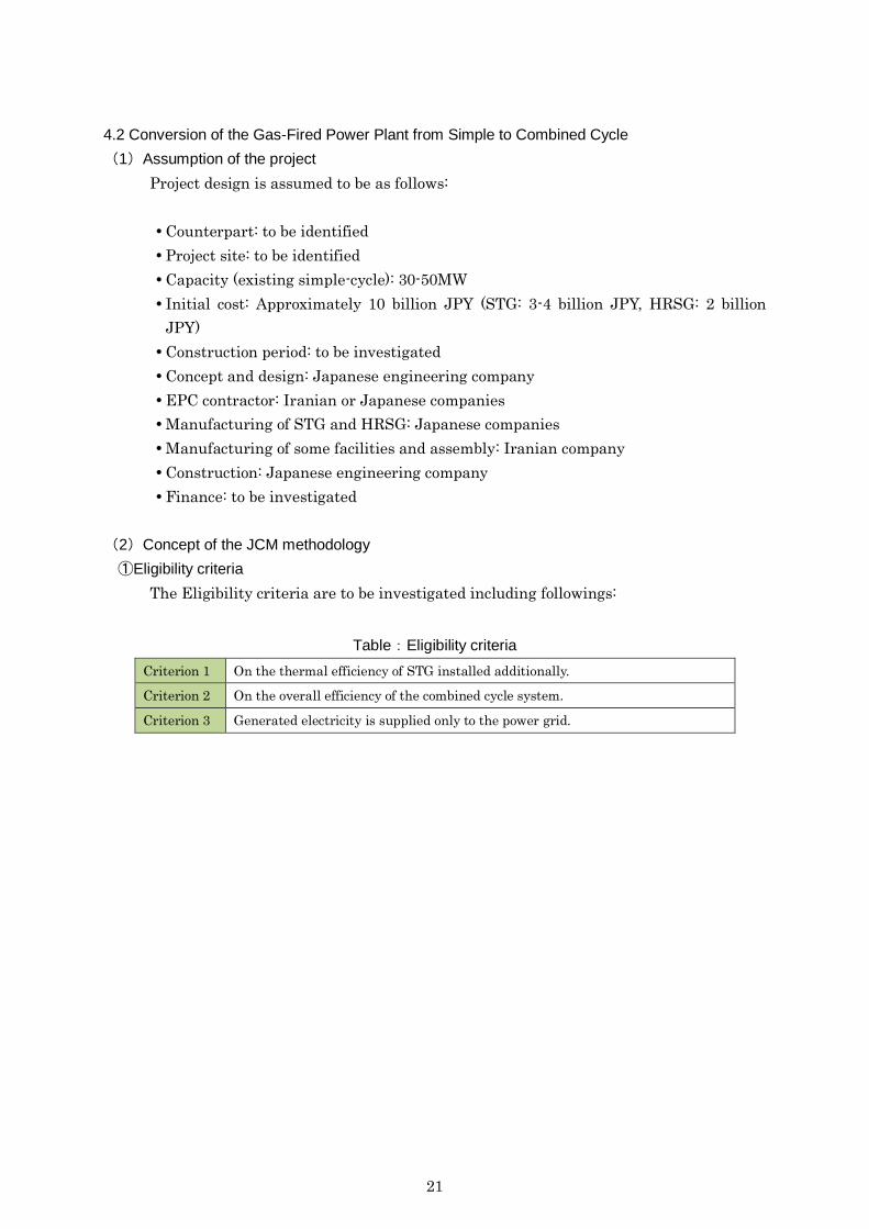
4.2 Conversion of the Gas-Fired Power Plant from Simple to Combined Cycle
(1)Assumption of the project
Project design is assumed to be as follows:
Counterpart: to be identified
Project site: to be identified
Capacity (existing simple-cycle): 30-50MW
Initial cost: Approximately 10 billion JPY (STG: 3-4 billion JPY, HRSG: 2 billion
JPY)
Construction period: to be investigated
Concept and design: Japanese engineering company
EPC contractor: Iranian or Japanese companies
Manufacturing of STG and HRSG: Japanese companies
Manufacturing of some facilities and assembly: Iranian company
Construction: Japanese engineering company
Finance: to be investigated
(2)Concept of the JCM methodology
①Eligibility criteria
The Eligibility criteria are to be investigated including followings:
Table:Eligibility criteria
Criterion 1 On the thermal efficiency of STG installed additionally.
Criterion 2 On the overall efficiency of the combined cycle system.
Criterion 3 Generated electricity is supplied only to the power grid.
22
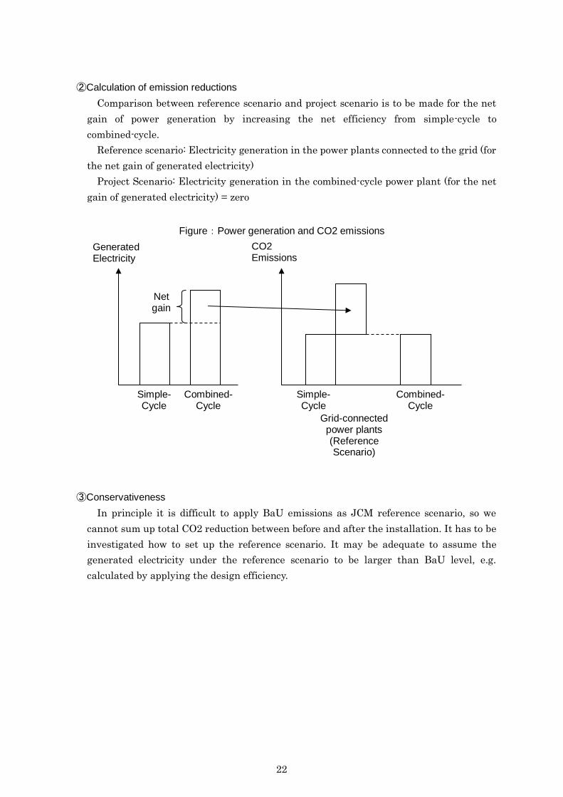
②Calculation of emission reductions
Comparison between reference scenario and project scenario is to be made for the net
gain of power generation by increasing the net efficiency from simple-cycle to
combined-cycle.
Reference scenario: Electricity generation in the power plants connected to the grid (for
the net gain of generated electricity)
Project Scenario: Electricity generation in the combined-cycle power plant (for the net
gain of generated electricity) = zero
Figure:Power generation and CO2 emissions
③Conservativeness
In principle it is difficult to apply BaU emissions as JCM reference scenario, so we
cannot sum up total CO2 reduction between before and after the installation. It has to be
investigated how to set up the reference scenario. It may be adequate to assume the
generated electricity under the reference scenario to be larger than BaU level, e.g.
calculated by applying the design efficiency.
Generated Electricity
Simple-Cycle
Combined-Cycle
Net gain
CO2 Emissions
Simple-Cycle
Combined-Cycle
Grid-connected power plants (Reference Scenario)
23
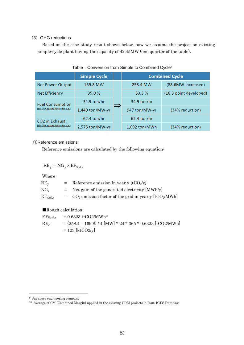
(3)GHG reductions
Based on the case study result shown below, now we assume the project on existing
simple-cycle plant having the capacity of 42.45MW (one quarter of the table).
Table:Conversion from Simple to Combined Cycle9
①Reference emissions
Reference emissions are calculated by the following equation:
yGrid,yy EFNGRE
Where
REy = Reference emission in year y [tCO2/y]
NGy = Net gain of the generated electricity [MWh/y]
EFGrid,y = CO2 emission factor of the grid in year y [tCO2/MWh]
■Rough calculation
EFGrid,y = 0.6323 t-CO2/MWh10
REy = (258.4 – 169.8) / 4 [MW] * 24 * 365 * 0.6323 [tCO2/MWh]
= 123 [ktCO2/y]
9 Japanese engineering company 10 Average of CM (Combined Margin) applied in the existing CDM projects in Iran: IGES Database
24
②Project emissions
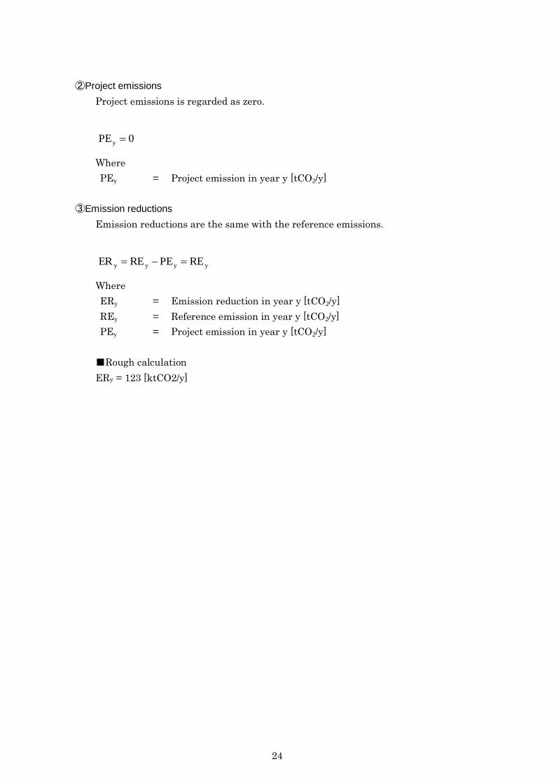
Project emissions is regarded as zero.
0PEy
Where
PEy = Project emission in year y [tCO2/y]
③Emission reductions
Emission reductions are the same with the reference emissions.
yyyy REPEREER
Where
ERy = Emission reduction in year y [tCO2/y]
REy = Reference emission in year y [tCO2/y]
PEy = Project emission in year y [tCO2/y]
■Rough calculation
ERy = 123 [ktCO2/y]

25
4.3 Low-loss transmission / distribution line
(1)Assumption of the project
Project design is assumed to be as follows:
Counterpart: Tavanir (if LL-ACSR/AS is installed in the national grid)
Initial cost: Around 3 million USD for 1 circuit, 100km length. (only transmission
lines; total construction cost is around 15 million USD.) (It depends on the technical
requirements in Iran.)
Manufacturing of steel wire: Japanese company
Manufacturing of aluminum wire and assembly: Iranian company (technology is to
be transferred by Japanese company)
EPC contractor: Japanese trading firm
Finance: to be investigated
26
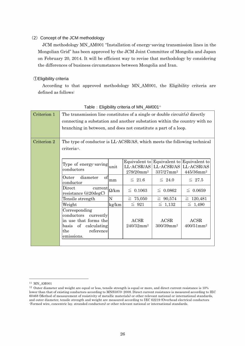
(2)Concept of the JCM methodology
JCM methodology MN_AM001 “Installation of energy-saving transmission lines in the
Mongolian Grid” has been approved by the JCM Joint Committee of Mongolia and Japan
on February 20, 2014. It will be efficient way to revise that methodology by considering
the differences of business circumstances between Mongolia and Iran.
①Eligibility criteria
According to that approved methodology MN_AM001, the Eligibility criteria are
defined as follows:
Table:Eligibility criteria of MN_AM00111
Criterion 1 The transmission line constitutes of a single or double circuit(s) directly
connecting a substation and another substation within the country with no
branching in between, and does not constitute a part of a loop.
Criterion 2 The type of conductor is LL-ACSR/AS, which meets the following technical
criteria12.
Type of energy-saving
conductors unit
Equivalent to
LL-ACSR/AS
279/20mm2
Equivalent to
LL-ACSR/AS
337/27mm2
Equivalent to
LL-ACSR/AS
445/36mm2
Outer diameter of
conductor mm ≦ 21.6 ≦ 24.0 ≦ 27.5
Direct current
resistance (@20degC) Ω/km ≦ 0.1063 ≦ 0.0862 ≦ 0.0659
Tensile strength N ≧ 75,050 ≧ 90,574 ≧ 120,481
Weight kg/km ≦ 921 ≦ 1,132 ≦ 1,490
Corresponding
conductors currently
in use that forms the
basis of calculating
the reference
emissions.
ACSR
240/32mm2
ACSR
300/39mm2
ACSR
400/51mm2
11 MN_AM001 12 Outer diameter and weight are equal or less, tensile strength is equal or more, and direct current resistance is 10%
lower than that of existing conductors according to MNS5870: 2008. Direct current resistance is measured according to IEC
60468 (Method of measurement of resistivity of metallic materials) or other relevant national or international standards,
and outer diameter, tensile strength and weight are measured according to IEC 62219 (Overhead electrical conductors
-Formed wire, concentric lay. stranded conductors) or other relevant national or international standards.
27
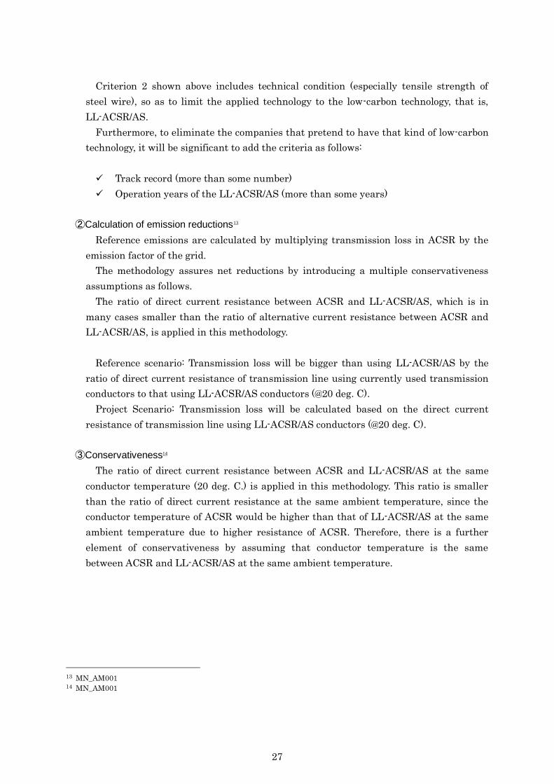
Criterion 2 shown above includes technical condition (especially tensile strength of
steel wire), so as to limit the applied technology to the low-carbon technology, that is,
LL-ACSR/AS.
Furthermore, to eliminate the companies that pretend to have that kind of low-carbon
technology, it will be significant to add the criteria as follows:
Track record (more than some number)
Operation years of the LL-ACSR/AS (more than some years)
②Calculation of emission reductions13
Reference emissions are calculated by multiplying transmission loss in ACSR by the
emission factor of the grid.
The methodology assures net reductions by introducing a multiple conservativeness
assumptions as follows.
The ratio of direct current resistance between ACSR and LL-ACSR/AS, which is in
many cases smaller than the ratio of alternative current resistance between ACSR and
LL-ACSR/AS, is applied in this methodology.
Reference scenario: Transmission loss will be bigger than using LL-ACSR/AS by the
ratio of direct current resistance of transmission line using currently used transmission
conductors to that using LL-ACSR/AS conductors (@20 deg. C).
Project Scenario: Transmission loss will be calculated based on the direct current
resistance of transmission line using LL-ACSR/AS conductors (@20 deg. C).
③Conservativeness14
The ratio of direct current resistance between ACSR and LL-ACSR/AS at the same
conductor temperature (20 deg. C.) is applied in this methodology. This ratio is smaller
than the ratio of direct current resistance at the same ambient temperature, since the
conductor temperature of ACSR would be higher than that of LL-ACSR/AS at the same
ambient temperature due to higher resistance of ACSR. Therefore, there is a further
element of conservativeness by assuming that conductor temperature is the same
between ACSR and LL-ACSR/AS at the same ambient temperature.
13 MN_AM001 14 MN_AM001
28
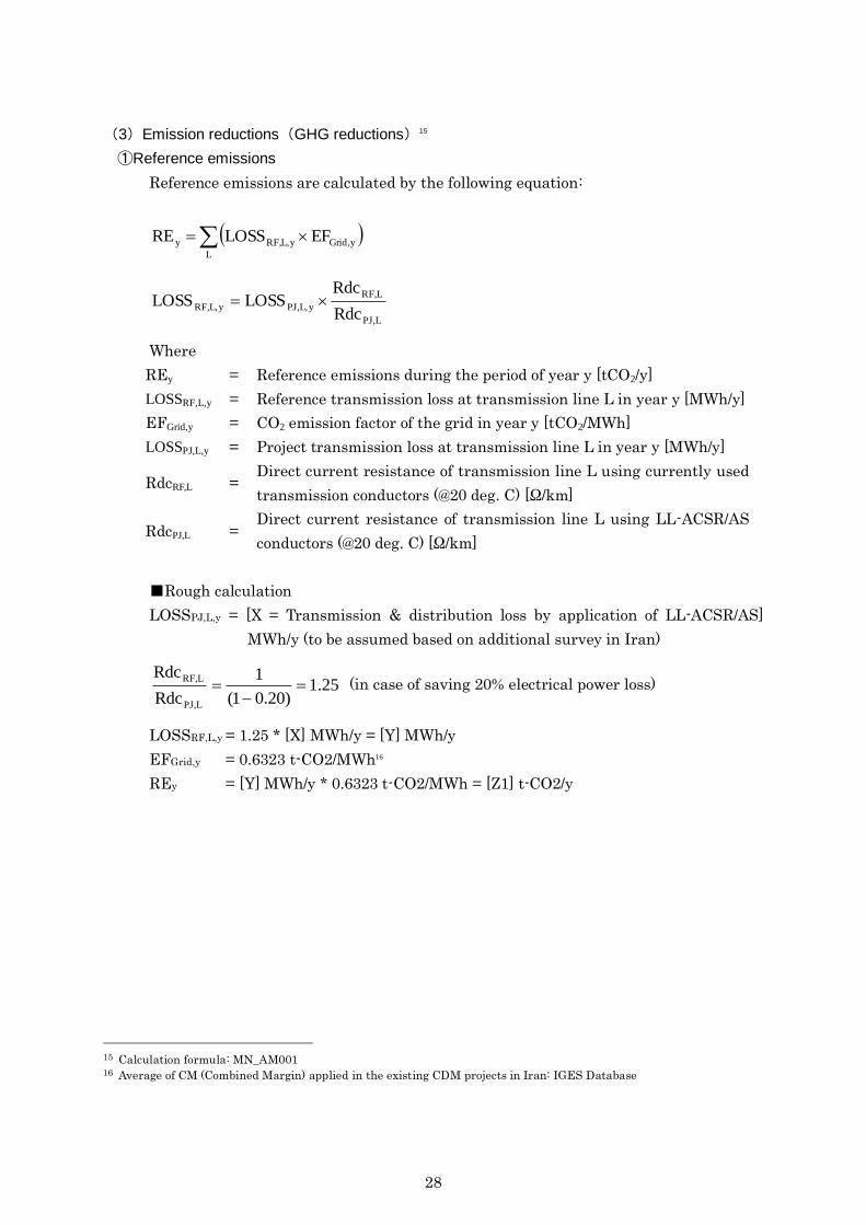
(3)Emission reductions(GHG reductions)15
①Reference emissions
Reference emissions are calculated by the following equation:
L
yGrid,yL,RF,y EFLOSSRE
LPJ,
LRF,
yL,PJ,yL,RF,Rdc
RdcLOSSLOSS
Where
REy = Reference emissions during the period of year y [tCO2/y]
LOSSRF,L,y = Reference transmission loss at transmission line L in year y [MWh/y]
EFGrid,y = CO2 emission factor of the grid in year y [tCO2/MWh]
LOSSPJ,L,y = Project transmission loss at transmission line L in year y [MWh/y]
RdcRF,L = Direct current resistance of transmission line L using currently used
transmission conductors (@20 deg. C) [Ω/km]
RdcPJ,L = Direct current resistance of transmission line L using LL-ACSR/AS
conductors (@20 deg. C) [Ω/km]
■Rough calculation
LOSSPJ,L,y = [X = Transmission & distribution loss by application of LL-ACSR/AS]
MWh/y (to be assumed based on additional survey in Iran)
25.1)20.01(
1
Rdc
Rdc
LPJ,
LRF,
(in case of saving 20% electrical power loss)
LOSSRF,L,y = 1.25 * [X] MWh/y = [Y] MWh/y
EFGrid,y = 0.6323 t-CO2/MWh16
REy = [Y] MWh/y * 0.6323 t-CO2/MWh = [Z1] t-CO2/y
15 Calculation formula: MN_AM001 16 Average of CM (Combined Margin) applied in the existing CDM projects in Iran: IGES Database
29
②Project emissions
Project emissions are calculated by multiplying transmission loss in the project
(LOSSPJ,L) by the CO2 emission factor of the grid (EFGrid,y):
L
yGrid,yL,PJ,y EFLOSSPE
yreceive,L,ysend,L,yL,PJ, E-ELOSS
Where
PEy = Project emissions during the period of year y [tCO2/y]
LOSSPJ,L,y = Project transmission loss at transmission line L in year y [MWh/y]
EL,send,y = Power sent from the point of origin/supply to the transmission line L in year y
[MWh/y]
EL,receive,y = Power received at the point of receipt of the transmission line L in year y
[MWh/y]
EFGrid,y = CO2 emission factor of the grid in year y [tCO2/MWh]
■Rough calculation
LOSSPJ,L,y = [X] MWh/y (to be assumed based on additional survey in Iran)
EFGrid,y = 0.6323 t-CO2/MWh
PEy = [X] MWh/y * 0.6323 t-CO2/MWh = [Z2] t-CO2/y
③Emission reductions
Emission reductions are calculated by the following equation:
yyy PEREER
Where
ERy = Emission reduction in year y [tCO2/y]
REy = Reference emission in year y [tCO2/y]
PEy = Project emission in year y [tCO2/y]
■Rough calculation
ERy = [Z1] t-CO2/y – [Z2] t-CO2/y
30
5.Analysis of the Benefit of both countries
5.1 Flare Gas Recovery
The South Pars Gas Field has a development zone of 24 phases and the gas is sent to a
gas refinery plant in Assaluyeh and refined.
The project can be expanded in the gas refinery plants in Assaluyeh, to which Natural
Gas mined in the South Pars Gas Field (24 phases) are sent.
Figure:GHG Reduction Potential (Flare Gas Recovery)
GHG Reduction Note
Model Project 723 kt-CO2/y
Potential 17,400 kt-CO2/y 24 Phases of the South Pars Gas Field
(1)Benefit for Japanese companies
Assumptions on the model project by identifying one phase of the South Pars Gas Field
are as follows:
Initial investment: Approx. 2.4-2.5 billion JPY (Japan: Iran = 1:1)
Project participants of Japan: Engineering company (e.g. EPC contractor,
design), manufacturing company (e.g. compressor, controlling system)
Project participants of Iran: Manufacturer (e.g. valve, supplemental facility,
assembly), constructing company (construction)
Benefit for Japanese companies are to be obtained by business contracts of those
projects (on Japanese portion).
Table:Benefit for project participants (Japan)
Benefit Note
Model Project 1.25 billion JPY 50% of the total initial investment
Potential 30 billion JPY 24 Phases of the South Pars Gas Field
(2)Benefit for Iranian companies
Benefit for Iranian companies are to be obtained by the following activities:
1) Business contracts of those projects (on Iranian portion)
2) Reduction of operation cost by recycling flare gas as additional material
3) Medium-to-long term business development by the technology transfer
As for 2) above, at this stage it is hard to estimate cost for obtaining natural gas from
the South Pars Gas Field, refinery cost in the Assaluyeh plant and additional revenue by
gaining raw material. As for 3), that revenue will be changed depending on the future
31
business models. Then, now we estimate benefit only on 1).
Table:Benefit for project participants (Iran)
Benefit Note
Model Project 1.25 billion JPY 50% of the total initial investment
Potential 30 billion JPY 24 Phases of the South Pars Gas Field
5.2 Conversion of the Gas-Fired Power Plant from Simple to Combined Cycle
Existing simple-cycle gas turbine is assumed to be as follows:
Typical capacity of the existing simple-cycle gas turbine is 30-50 MW.
There are more than operating 40 simple-cycle gas turbines, thermal efficiency of
which is not good, and the total capacity is assumed to be more than 20,000 MW.
Supposing to implement 40 similar projects, GHG reduction potential is roughly
estimated.
Table:GHG Reduction Potential (Conversion from Simple-cycle to Combined cycle)
GHG Reduction Note
Model Project 123 kt-CO2/y 42.5 MW
Potential 4,920 kt-CO2/y 40 plants
(1)Benefit for Japanese companies
Assumptions on the model project are as follows:
Initial investment: Approx. 10 billion JPY (Japan: Iran = 7: 3)
Project participants of Japan: Engineering company (e.g. EPC contractor,
design), manufacturing company (e.g. STG, HRSG)
Project participants of Iran: Manufacturing company (e.g. supplemental
facilities, assembly), constructing company (construction)
Benefit for Japanese companies are to be obtained by business contracts of those
projects (on Japanese portion).
Table:Benefit for project participants (Japan)
Benefit Note
Model Project 7 billion JPY 70% of the total initial investment
Potential 280 billion JPY 40 plants
32
(2)Benefit for Iranian companies
Benefit for Iranian companies are to be obtained by the following activities:
1) Business contracts of those projects (on Iranian portion)
2) Additional generated electricity to be sold
3) Medium-to-long term business development by the technology transfer
As for 3) above, that revenue will be changed depending on the future business models.
Then, now we estimate benefit on 1) and 2).
As for 2), additional generated electricity will be as follows:
Gains of power generation = (258.4 – 169.8) / 4 [MW] * 24 * 365
= 194,000 [MWh/y]
Assuming the wholesale electricity price as 680 IRR/kWh17,
Increase of revenue= 194,000 [MWh/y] * 680 * 1,000 [IRR/MWh] * 0.003725 [JPY/IRR]
= 491 [million JPY/y]
Table:Benefit for project participants (Iran)
Benefit Note
Model Project 3 billion JPY 30% of the total initial investment
491 million JPY/y Increase of electricity selling revenue
Potential 120 billion JPY 40 plants
19.6 billion JPY/y Increase of electricity selling revenue
5.3 Low-loss transmission / distribution line
GHG reduction potential by promoting application of low-loss transmission /
distribution line depends on the development plan of the power grid.
(1)Benefit for Iranian companies and Japanise companies
It depends on the scale of business.
17 Electricity generation cost: Trend News Agency (2014/2/28) http://en.trend.az/iran/2247258.html
33
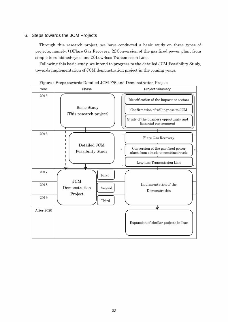
6.Steps towards the JCM Projects
Through this research project, we have conducted a basic study on three types of
projects, namely, (1)Flare Gas Recovery, (2)Conversion of the gas-fired power plant from
simple to combined-cycle and (3)Low-loss Transmission Line.
Following this basic study, we intend to progress to the detailed JCM Feasibility Study,
towards implementation of JCM demonstration project in the coming years.
Figure:Steps towards Detailed JCM F/S and Demonstration Project
Year Phase Project Summary
2015
2016
2017
2018
2019
After 2020
Basic Study
(This research project)
Identification of the important sectors
Confirmation of willingness to JCM
Study of the business opportunity and
financial environment
Detailed JCM
Feasibility Study
JCM
Demonstration
Project
First
Flare Gas Recovery
Conversion of the gas-fired power
plant from simple to combined-cycle
Low-loss Transmission Line
Implementation of the
Demonstration Second
Third
Expansion of similar projects in Iran
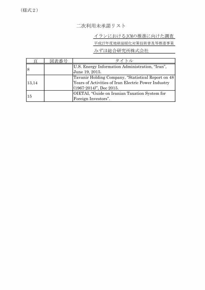
(様式2)
頁 図表番号
8
13,14
15
タイトルU.S. Energy Information Administration, “Iran”,
June 19, 2015.
Tavanir Holding Company, “Statistical Report on 48
Years of Activities of Iran Electric Power Industry
(1967-2014)”, Dec 2015.
OIETAI, “Guide on Iranian Taxation System for
Foreign Investors”.
二次利用未承諾リスト
平成27年度地球温暖化対策技術普及等推進事業
イランにおけるJCMの推進に向けた調査
みずほ総合研究所株式会社