Embed Size (px)
Citation preview

Basic Vocational Knowledge − Electrical Machines
Table of ContentsBasic Vocational Knowledge − Electrical Machines......................................................................................1
Introduction.............................................................................................................................................11. General information about electrical machines...................................................................................2
1.1. Definition of terms.....................................................................................................................21.2. Types of electrical machines.....................................................................................................21.3. Operations of electrical machines.............................................................................................21.4. System of rotating electrical machines (generators, motors, converters).................................31.5. System of stationary electrical machines (transformers)...........................................................3
2. Basic principles...................................................................................................................................42.1. The magnetic field.....................................................................................................................42.2. Measurable variables of the magnetic field.............................................................................112.3. Force action of the magnetic field...........................................................................................132.4. Voltage generation through induction.....................................................................................15
3. Execution of rotating electrical machines.........................................................................................183.1. Size.........................................................................................................................................183.2. Designs...................................................................................................................................193.3. Degree of protection................................................................................................................213.4. Cooling....................................................................................................................................223.5. Mode of operation...................................................................................................................243.6. Heat resistance categories......................................................................................................263.7. Connection designations of electrical machines.....................................................................273.8. Rotating electrical machines in rotational sense.....................................................................283.9. Rating plate.............................................................................................................................28
4. Synchronous machines....................................................................................................................304.1. Operating principles................................................................................................................304.2. Constructional assembly.........................................................................................................344.3. Operational behaviour.............................................................................................................364.4. Use of synchronous machines................................................................................................42
5. Asynchronous motors.......................................................................................................................435.1. Constructional assembly.........................................................................................................435.2. Operating principles................................................................................................................455.3. Operational behaviour.............................................................................................................485.4. Circuit engineering..................................................................................................................525.5. Application...............................................................................................................................705.6. Characteristic values of squirrel cage motors.........................................................................70
6. Direct current machines....................................................................................................................716.1. Constructional assembly.........................................................................................................716.2. Operating principles................................................................................................................736.3. Operational behaviour of direct current machines..................................................................806.4. Circuit engineering and operational features of customary direct current generators.............846.5. Circuit engineering and operational features of customary direct current motors...................87
7. Single−phase alternating current motors..........................................................................................917.1. Single−phase asynchronous motors (single−phase induction motors)...................................917.2. Three−phase asynchronous motor in single−phase operation (capacitor motor)...................967.3. Split pole motors.....................................................................................................................967.4. Single−phase commutator motors (universal motors).............................................................97
8. Transformer....................................................................................................................................1028.1. Transformer principle............................................................................................................1028.2. Operational behaviour of a transformer................................................................................1068.3. Three−phase transformer......................................................................................................112
i
1. General information about electrical machines
1.1. Definition of terms
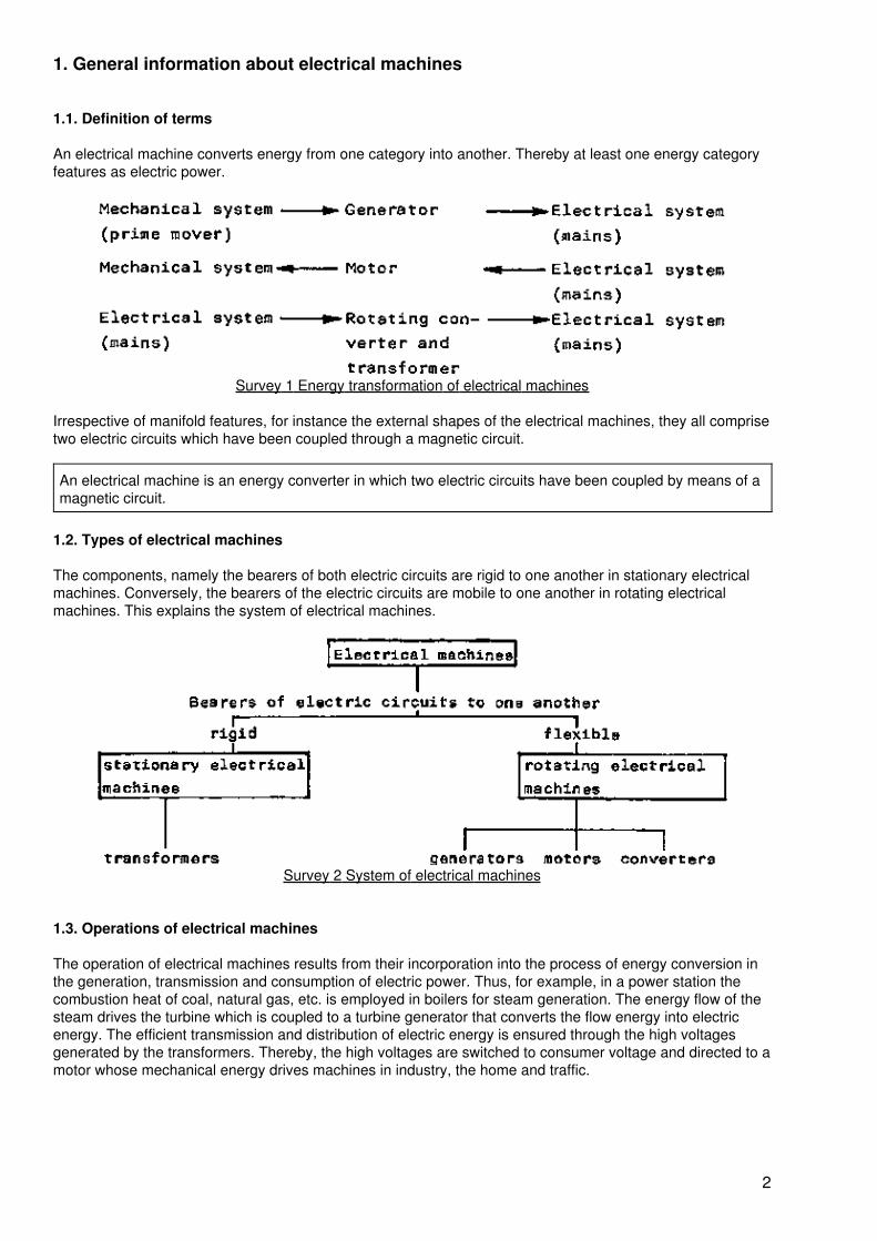
An electrical machine converts energy from one category into another. Thereby at least one energy categoryfeatures as electric power.
Survey 1 Energy transformation of electrical machines
Irrespective of manifold features, for instance the external shapes of the electrical machines, they all comprisetwo electric circuits which have been coupled through a magnetic circuit.
An electrical machine is an energy converter in which two electric circuits have been coupled by means of amagnetic circuit.
1.2. Types of electrical machines
The components, namely the bearers of both electric circuits are rigid to one another in stationary electricalmachines. Conversely, the bearers of the electric circuits are mobile to one another in rotating electricalmachines. This explains the system of electrical machines.
Survey 2 System of electrical machines
1.3. Operations of electrical machines
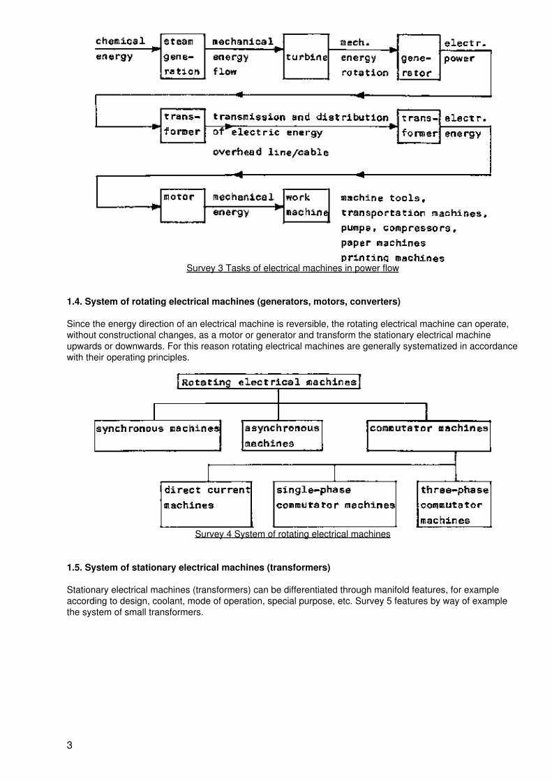
The operation of electrical machines results from their incorporation into the process of energy conversion inthe generation, transmission and consumption of electric power. Thus, for example, in a power station thecombustion heat of coal, natural gas, etc. is employed in boilers for steam generation. The energy flow of thesteam drives the turbine which is coupled to a turbine generator that converts the flow energy into electricenergy. The efficient transmission and distribution of electric energy is ensured through the high voltagesgenerated by the transformers. Thereby, the high voltages are switched to consumer voltage and directed to amotor whose mechanical energy drives machines in industry, the home and traffic.
2
Survey 3 Tasks of electrical machines in power flow
1.4. System of rotating electrical machines (generators, motors, converters)
Since the energy direction of an electrical machine is reversible, the rotating electrical machine can operate,without constructional changes, as a motor or generator and transform the stationary electrical machineupwards or downwards. For this reason rotating electrical machines are generally systematized in accordancewith their operating principles.
Survey 4 System of rotating electrical machines
1.5. System of stationary electrical machines (transformers)
Stationary electrical machines (transformers) can be differentiated through manifold features, for exampleaccording to design, coolant, mode of operation, special purpose, etc. Survey 5 features by way of examplethe system of small transformers.
3
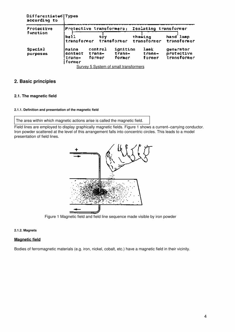
Survey 5 System of small transformers
2. Basic principles
2.1. The magnetic field
2.1.1. Definition and presentation of the magnetic field
The area within which magnetic actions arise is called the magnetic field.
Field lines are employed to display graphically magnetic fields. Figure 1 shows a current−carrying conductor.Iron powder scattered at the level of this arrangement falls into concentric circles. This leads to a modelpresentation of field lines.
Figure 1 Magnetic field and field line sequence made visible by iron powder
2.1.2. Magnets
Magnetic field
Bodies of ferromagnetic materials (e.g. iron, nickel, cobalt, etc.) have a magnetic field in their vicinity.
4
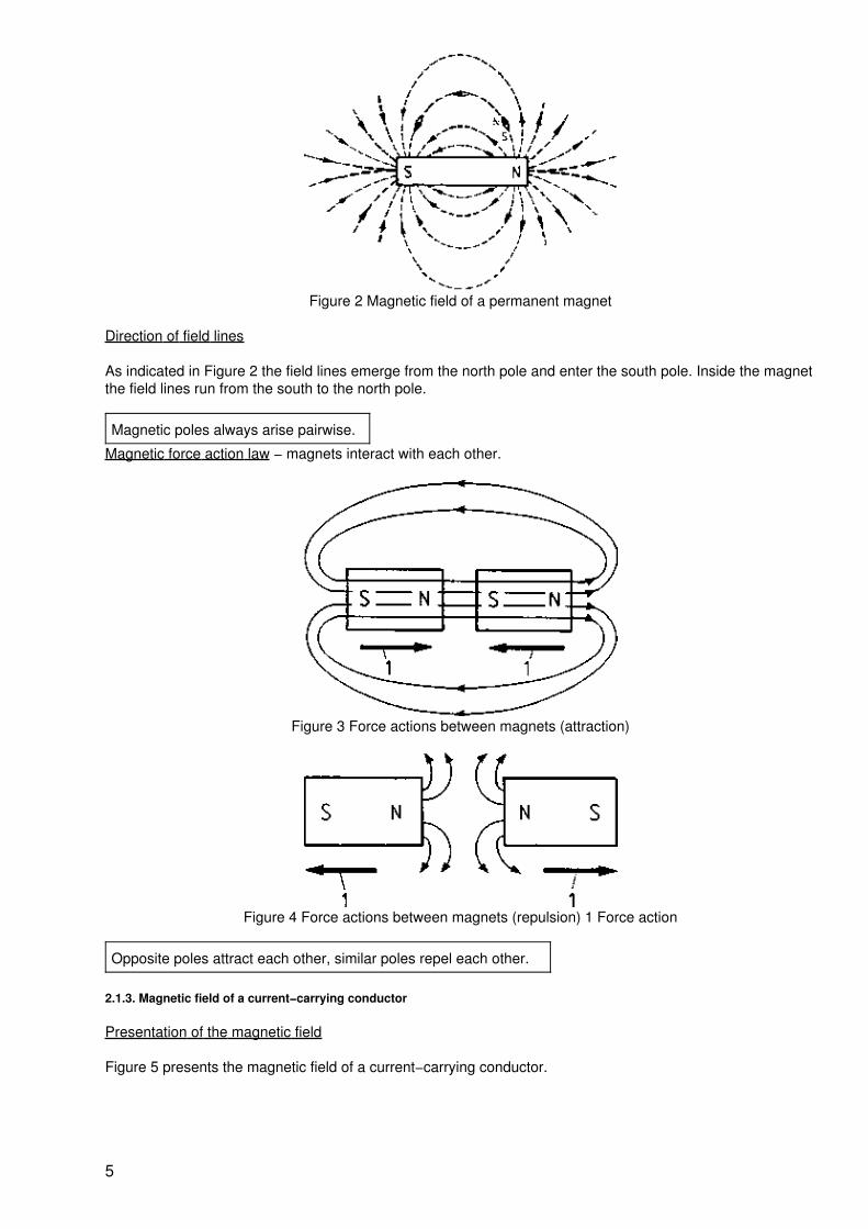
Figure 2 Magnetic field of a permanent magnet
Direction of field lines
As indicated in Figure 2 the field lines emerge from the north pole and enter the south pole. Inside the magnetthe field lines run from the south to the north pole.
Magnetic poles always arise pairwise.
Magnetic force action law − magnets interact with each other.
Figure 3 Force actions between magnets (attraction)
Figure 4 Force actions between magnets (repulsion) 1 Force action
Opposite poles attract each other, similar poles repel each other.
2.1.3. Magnetic field of a current−carrying conductor
Presentation of the magnetic field
Figure 5 presents the magnetic field of a current−carrying conductor.
5
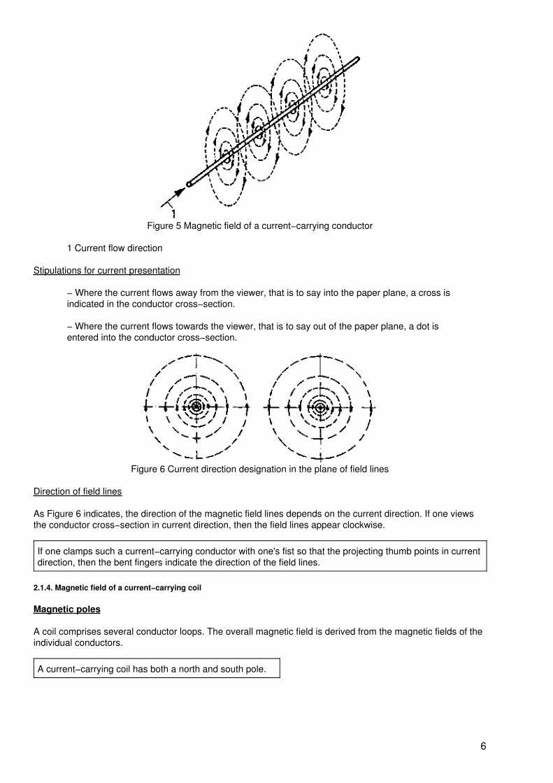
Figure 5 Magnetic field of a current−carrying conductor
1 Current flow direction
Stipulations for current presentation
− Where the current flows away from the viewer, that is to say into the paper plane, a cross isindicated in the conductor cross−section.
− Where the current flows towards the viewer, that is to say out of the paper plane, a dot isentered into the conductor cross−section.
Figure 6 Current direction designation in the plane of field lines
Direction of field lines
As Figure 6 indicates, the direction of the magnetic field lines depends on the current direction. If one viewsthe conductor cross−section in current direction, then the field lines appear clockwise.
If one clamps such a current−carrying conductor with one's fist so that the projecting thumb points in currentdirection, then the bent fingers indicate the direction of the field lines.
2.1.4. Magnetic field of a current−carrying coil
Magnetic poles
A coil comprises several conductor loops. The overall magnetic field is derived from the magnetic fields of theindividual conductors.
A current−carrying coil has both a north and south pole.
6
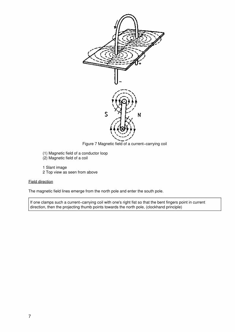
Figure 7 Magnetic field of a current−carrying coil
(1) Magnetic field of a conductor loop(2) Magnetic field of a coil
1 Slant image2 Top view as seen from above
Field direction
The magnetic field lines emerge from the north pole and enter the south pole.
If one clamps such a current−carrying coil with one's right fist so that the bent fingers point in currentdirection, then the projecting thumb points towards the north pole, (clockhand principle)
7
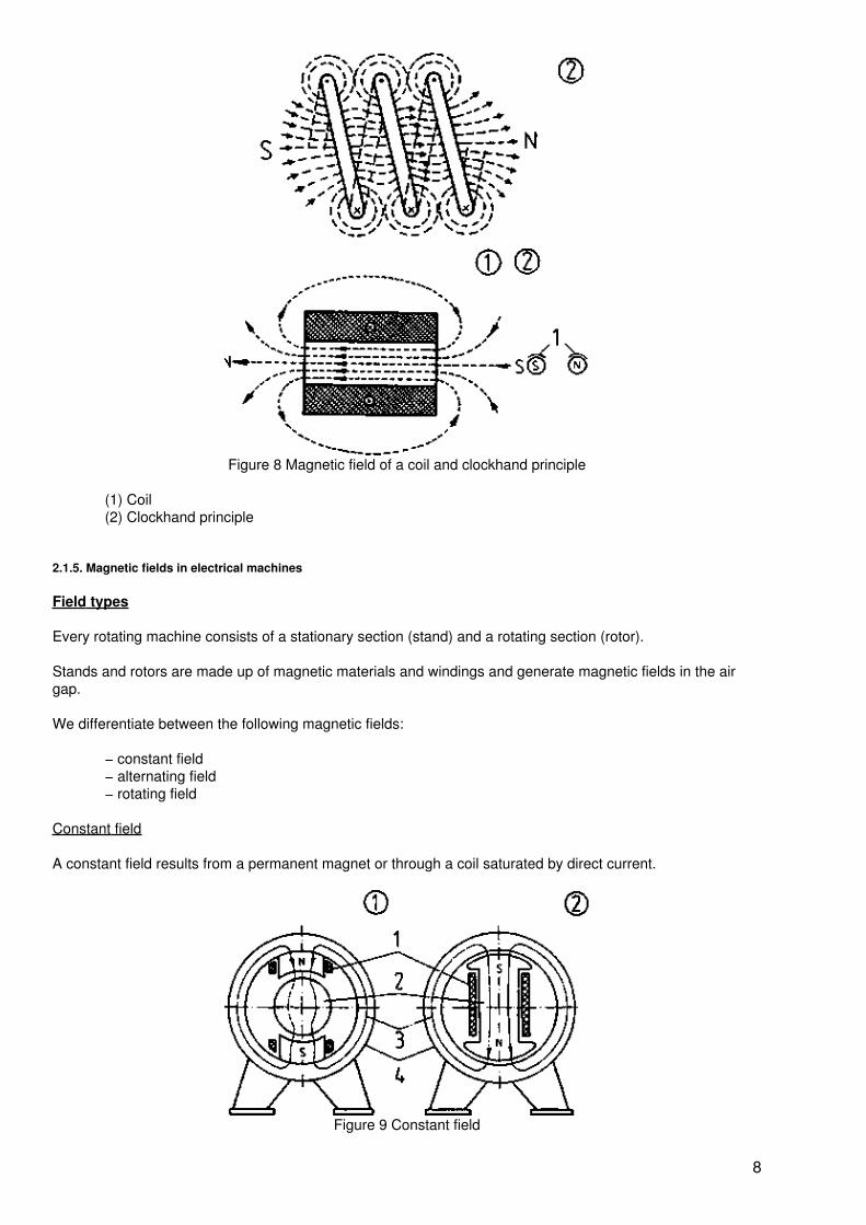
Figure 8 Magnetic field of a coil and clockhand principle
(1) Coil(2) Clockhand principle
2.1.5. Magnetic fields in electrical machines
Field types
Every rotating machine consists of a stationary section (stand) and a rotating section (rotor).
Stands and rotors are made up of magnetic materials and windings and generate magnetic fields in the airgap.
We differentiate between the following magnetic fields:
− constant field− alternating field− rotating field
Constant field
A constant field results from a permanent magnet or through a coil saturated by direct current.
Figure 9 Constant field
8
(1) Rotor excitation through current flow(2) Stator excitation through current flow
1 Field winding, 2 Rotor3 Magnetic flow, 4 Stator
A constant field denotes a temporally constant magnetic field in an air gap.
Alternating field
An alternating field is generated as alternating current passes through a winding.
A magnetic field which changes its size and direction according to the frequency is called an alternatingfield.
Figure 10 Magnetic alternating field
1 Alternating current, 2 Induction and current, 3 Induction sequence, 4 Current sequence
Rotating field
Definition of term:
A rotating field may be compared to the magnetic field of a rotating, permanent magnet.
Figure 11 Emergence of a rotating field through rotation of a permanent magnet
A rotating field denotes a rotating magnetic field within a specific space.
Generating a rotating field:
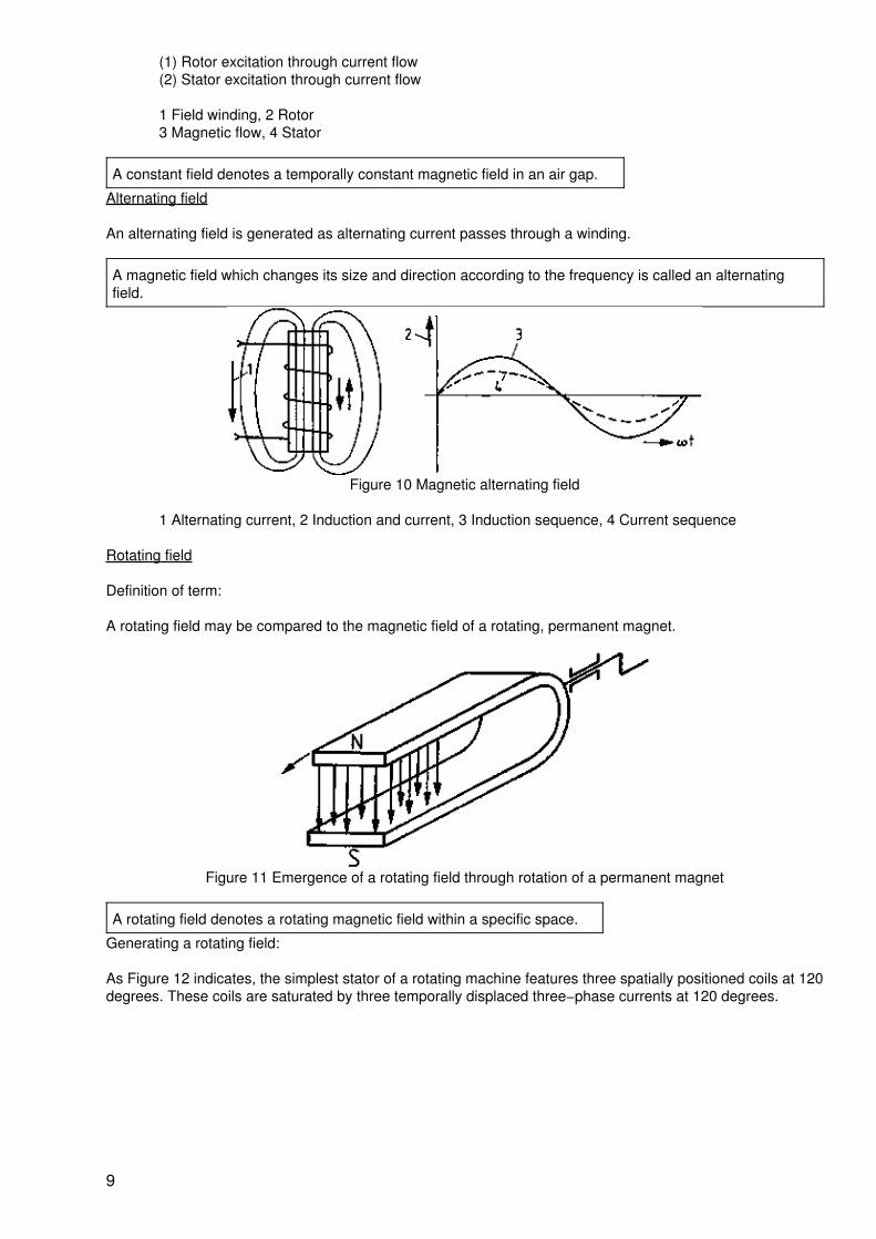
As Figure 12 indicates, the simplest stator of a rotating machine features three spatially positioned coils at 120degrees. These coils are saturated by three temporally displaced three−phase currents at 120 degrees.
9
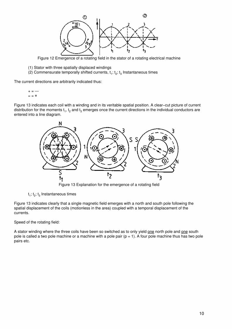
Figure 12 Emergence of a rotating field in the stator of a rotating electrical machine
(1) Stator with three spatially displaced windings(2) Commensurate temporally shifted currents, t1; t2; t3 Instantaneous times
The current directions are arbitrarily indicated thus:
+ = —− = ¤
Figure 13 indicates each coil with a winding and in its veritable spatial position. A clear−cut picture of currentdistribution for the moments t1, t2 and t3 emerges once the current directions in the individual conductors areentered into a line diagram.
Figure 13 Explanation for the emergence of a rotating field
t1; t2; t3 Instantaneous times
Figure 13 indicates clearly that a single magnetic field emerges with a north and south pole following thespatial displacement of the coils (motionless in the area) coupled with a temporal displacement of thecurrents.
Speed of the rotating field:
A stator winding where the three coils have been so switched as to only yield one north pole and one southpole is called a two pole machine or a machine with a pole pair (p = 1). A four pole machine thus has two polepairs etc.
10
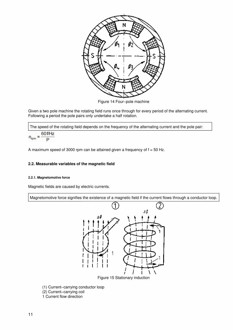
Figure 14 Four−pole machine
Given a two pole machine the rotating field runs once through for every period of the alternating current.Following a period the pole pairs only undertake a half rotation.
The speed of the rotating field depends on the frequency of the alternating current and the pole pair:
A maximum speed of 3000 rpm can be attained given a frequency of f = 50 Hz.
2.2. Measurable variables of the magnetic field
2.2.1. Magnetomotive force
Magnetic fields are caused by electric currents.
Magnetomotive force signifies the existence of a magnetic field if the current flows through a conductor loop.
Figure 15 Stationary induction
(1) Current−carrying conductor loop(2) Current−carrying coil1 Current flow direction
11
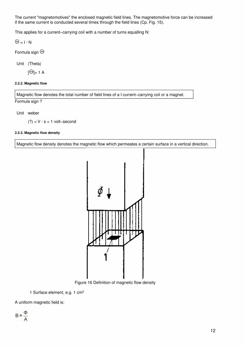
The current "magnetomotives" the enclosed magnetic field lines. The magnetomotive force can be increasedif the same current is conducted several times through the field lines (Cp. Fig. 15).
This applies for a current−carrying coil with a number of turns equalling N:
= I · N
Formula sign
Unit (Theta)
[ ]= 1 A
2.2.2. Magnetic flow
Magnetic flow denotes the total number of field lines of a I current−carrying coil or a magnet.
Formula sign ?
Unit weber
(?) = V · s = 1 volt−second
2.2.3. Magnetic flow density
Magnetic flow density denotes the magnetic flow which permeates a certain surface in a vertical direction.
Figure 16 Definition of magnetic flow density
1 Surface element, e.g. 1 cm2
A uniform magnetic field is:
12
Formula sign B
Unit tesla
2.3. Force action of the magnetic field
2.3.1. Force action on current−carrying conductors
Operating principle
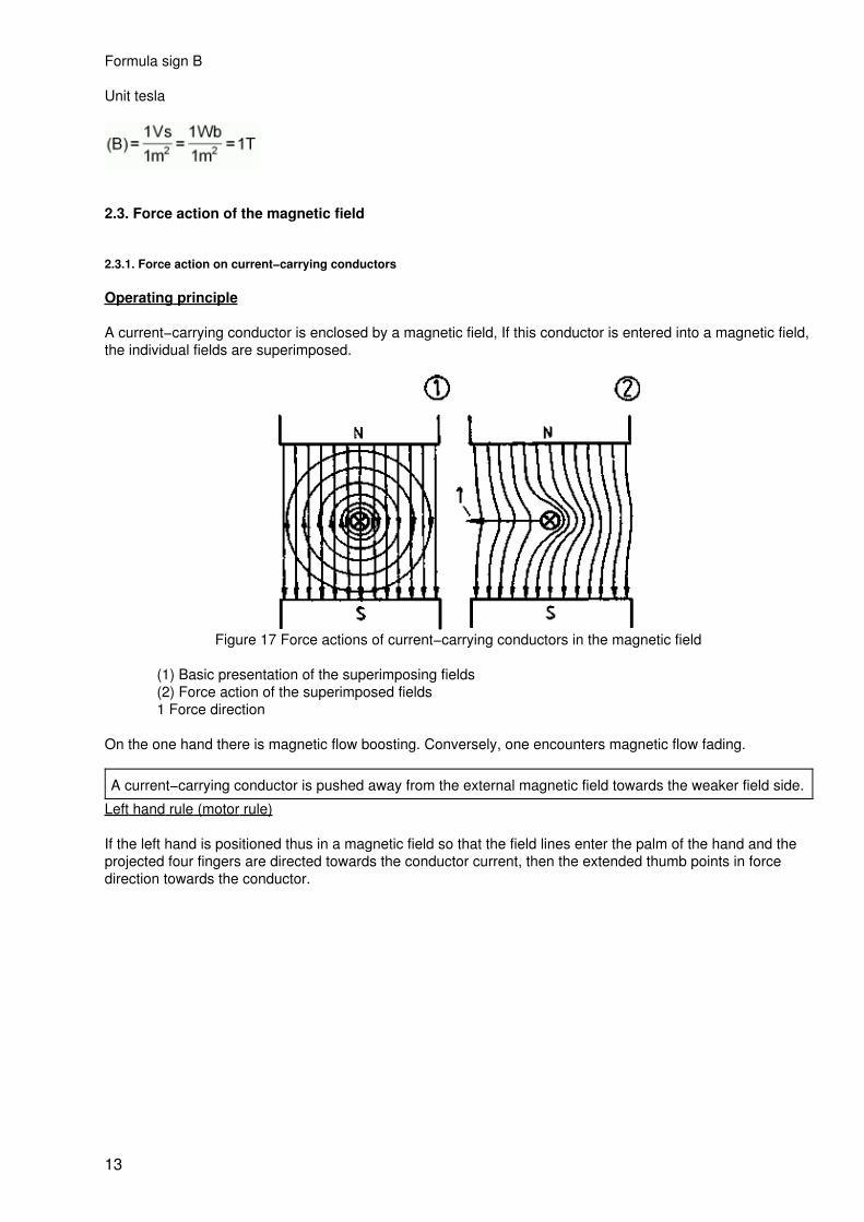
A current−carrying conductor is enclosed by a magnetic field, If this conductor is entered into a magnetic field,the individual fields are superimposed.
Figure 17 Force actions of current−carrying conductors in the magnetic field
(1) Basic presentation of the superimposing fields(2) Force action of the superimposed fields1 Force direction
On the one hand there is magnetic flow boosting. Conversely, one encounters magnetic flow fading.
A current−carrying conductor is pushed away from the external magnetic field towards the weaker field side.
Left hand rule (motor rule)
If the left hand is positioned thus in a magnetic field so that the field lines enter the palm of the hand and theprojected four fingers are directed towards the conductor current, then the extended thumb points in forcedirection towards the conductor.
13
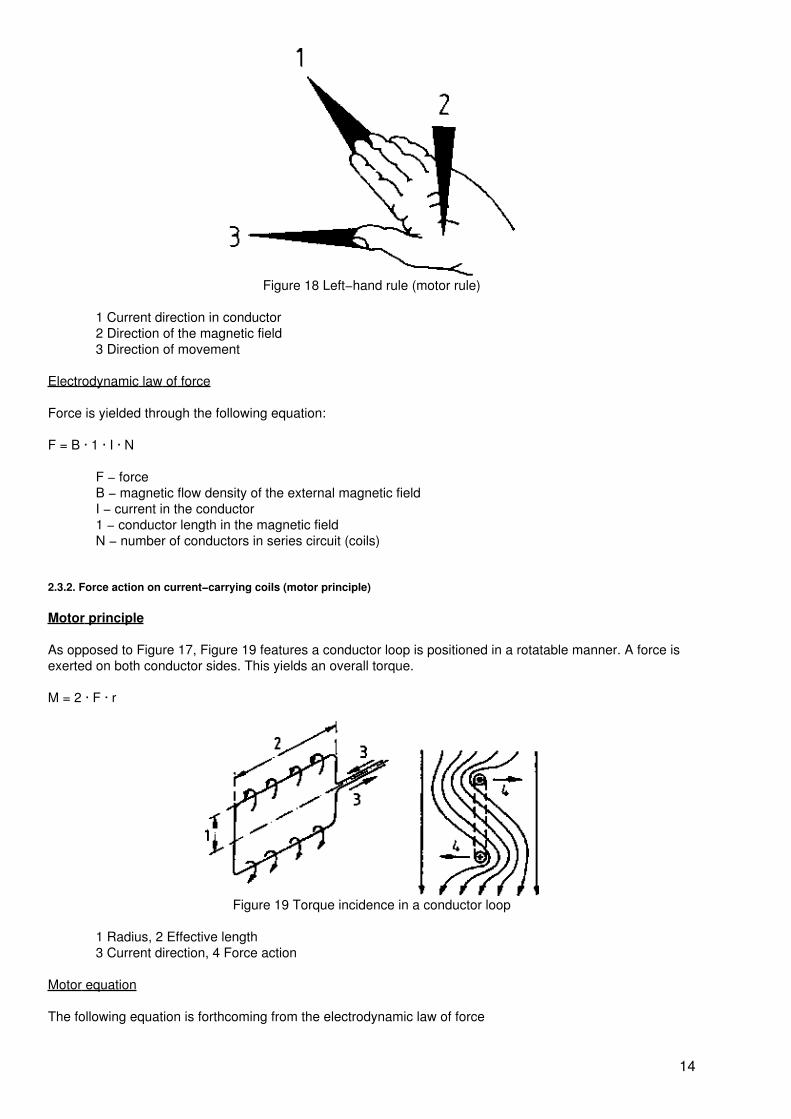
Figure 18 Left−hand rule (motor rule)
1 Current direction in conductor2 Direction of the magnetic field3 Direction of movement
Electrodynamic law of force
Force is yielded through the following equation:
F = B · 1 · I · N
F − forceB − magnetic flow density of the external magnetic fieldI − current in the conductor1 − conductor length in the magnetic fieldN − number of conductors in series circuit (coils)
2.3.2. Force action on current−carrying coils (motor principle)
Motor principle
As opposed to Figure 17, Figure 19 features a conductor loop is positioned in a rotatable manner. A force isexerted on both conductor sides. This yields an overall torque.
M = 2 · F · r
Figure 19 Torque incidence in a conductor loop
1 Radius, 2 Effective length3 Current direction, 4 Force action
Motor equation
The following equation is forthcoming from the electrodynamic law of force
14
M = 2 · B · l · I · N · r
M = c · ? · I
c − machine constants (constructive values) magnetic flow of the external magnetic fieldI − current in the conductor loop or coil
2.4. Voltage generation through induction
2.4.1. General law of induction
A voltage is induced where a circuit is saturated through a temporally altering magnetic flow.
2.4.2. Stationary induction (transformer principle)
Given stationary induction (Figure 15), the magnetic flow alteration is generated by means of a stationaryconductor loop or coil and a temporally changeable magnetic flow.
2.4.3. Motional induction (generator principle)
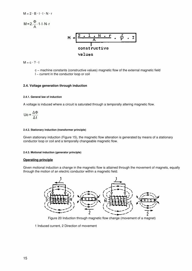
Operating principle
Given motional induction a change in the magnetic flow is attained through the movement of magnets, equallythrough the motion of an electric conductor within a magnetic field.
Figure 20 Induction through magnetic flow change (movement of a magnet)
1 Induced current, 2 Direction of movement
15
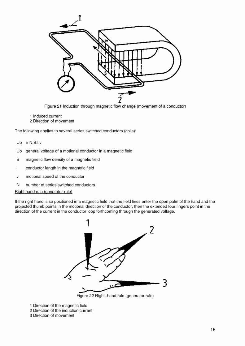
Figure 21 Induction through magnetic flow change (movement of a conductor)
1 Induced current2 Direction of movement
The following applies to several series switched conductors (coils):
Uo = N.B.l.v
Uo general voltage of a motional conductor in a magnetic field
B magnetic flow density of a magnetic field
l conductor length in the magnetic field
v motional speed of the conductor
N number of series switched conductors
Right hand rule (generator rule)
If the right hand is so positioned in a magnetic field that the field lines enter the open palm of the hand and theprojected thumb points in the motional direction of the conductor, then the extended four fingers point in thedirection of the current in the conductor loop forthcoming through the generated voltage.
Figure 22 Right−hand rule (generator rule)
1 Direction of the magnetic field2 Direction of the induction current3 Direction of movement
16
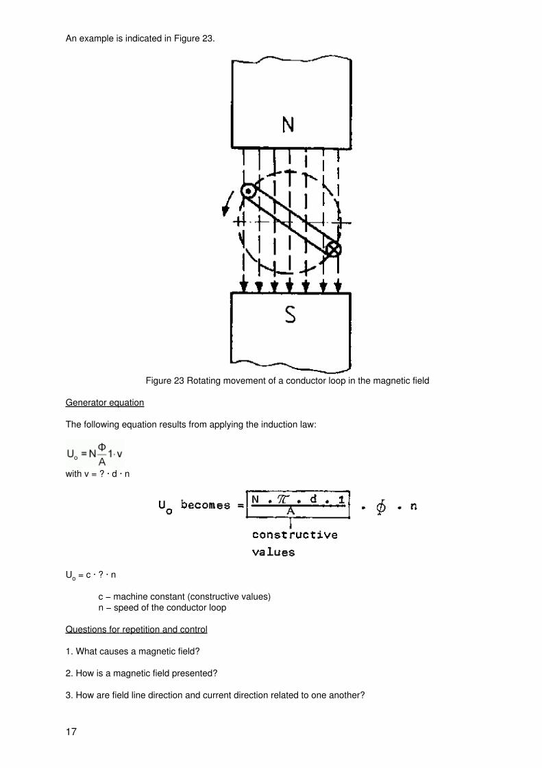
An example is indicated in Figure 23.
Figure 23 Rotating movement of a conductor loop in the magnetic field
Generator equation
The following equation results from applying the induction law:
with v = ? · d · n
Uo = c · ? · n
c − machine constant (constructive values)n − speed of the conductor loop
Questions for repetition and control
1. What causes a magnetic field?
2. How is a magnetic field presented?
3. How are field line direction and current direction related to one another?
17
4. What are the differences between a magnetic constant field and an alternating field?
5. How is a rotating field generated?
6. What does the speed of the rotating field depend on?
7. What is meant by magnetomotive force?
8. How are magnetic flow and magnetic flow density interrelated?
9. How are the forces directed which similar and opposite magnetic poles exert to one another?
10. Describe the left hand rule.
11. Which values exert an influence on the torque of a motor?
12. Describe the right hand rule.
13. Which values are of decisive importance for the induced voltage in a generator?
3. Execution of rotating electrical machines
3.1. Size
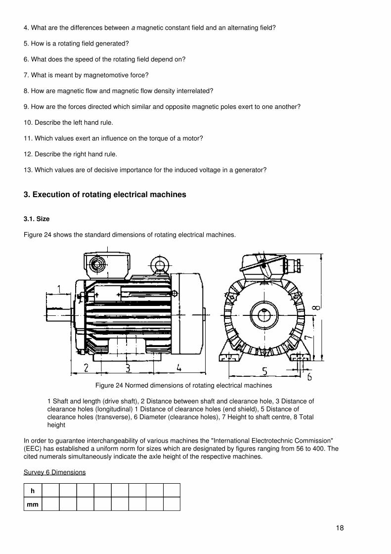
Figure 24 shows the standard dimensions of rotating electrical machines.
Figure 24 Normed dimensions of rotating electrical machines
1 Shaft and length (drive shaft), 2 Distance between shaft and clearance hole, 3 Distance ofclearance holes (longitudinal) 1 Distance of clearance holes (end shield), 5 Distance ofclearance holes (transverse), 6 Diameter (clearance holes), 7 Height to shaft centre, 8 Totalheight
In order to guarantee interchangeability of various machines the "International Electrotechnic Commission"(EEC) has established a uniform norm for sizes which are designated by figures ranging from 56 to 400. Thecited numerals simultaneously indicate the axle height of the respective machines.
Survey 6 Dimensions
h
mm
18
56 63 71 80 90 100 112 132 160
18 200 225 250 280 315 355 400
3.2. Designs
3.2.1. Definition
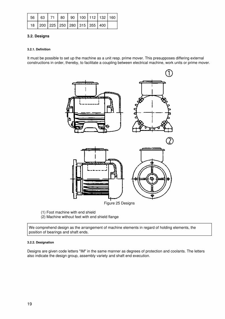
It must be possible to set up the machine as a unit resp. prime mover. This presupposes differing externalconstructions in order, thereby, to facilitate a coupling between electrical machine, work units or prime mover.
Figure 25 Designs
(1) Foot machine with end shield(2) Machine without feet with end shield flange
We comprehend design as the arrangement of machine elements in regard of holding elements, theposition of bearings and shaft ends.
3.2.2. Designation
Designs are given code letters "IM" in the same manner as degrees of protection and coolants. The lettersalso indicate the design group, assembly variety and shaft end execution.
19
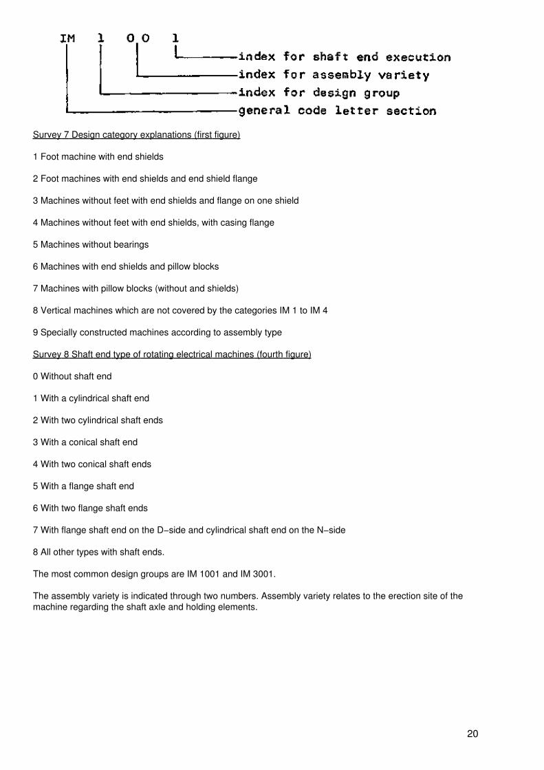
Survey 7 Design category explanations (first figure)
1 Foot machine with end shields
2 Foot machines with end shields and end shield flange
3 Machines without feet with end shields and flange on one shield
4 Machines without feet with end shields, with casing flange
5 Machines without bearings
6 Machines with end shields and pillow blocks
7 Machines with pillow blocks (without and shields)
8 Vertical machines which are not covered by the categories IM 1 to IM 4
9 Specially constructed machines according to assembly type
Survey 8 Shaft end type of rotating electrical machines (fourth figure)
0 Without shaft end
1 With a cylindrical shaft end
2 With two cylindrical shaft ends
3 With a conical shaft end
4 With two conical shaft ends
5 With a flange shaft end
6 With two flange shaft ends
7 With flange shaft end on the D−side and cylindrical shaft end on the N−side
8 All other types with shaft ends.
The most common design groups are IM 1001 and IM 3001.
The assembly variety is indicated through two numbers. Assembly variety relates to the erection site of themachine regarding the shaft axle and holding elements.
20
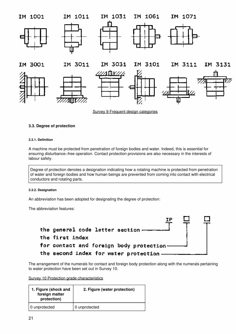
Survey 9 Frequent design categories
3.3. Degree of protection
3.3.1. Definition
A machine must be protected from penetration of foreign bodies and water. Indeed, this is essential forensuring disturbance−free operation. Contact protection provisions are also necessary in the interests oflabour safety.
Degree of protection denotes a designation indicating how a rotating machine is protected from penetrationof water and foreign bodies and how human beings are prevented from coming into contact with electricalconductors and rotating parts.
3.3.2. Designation
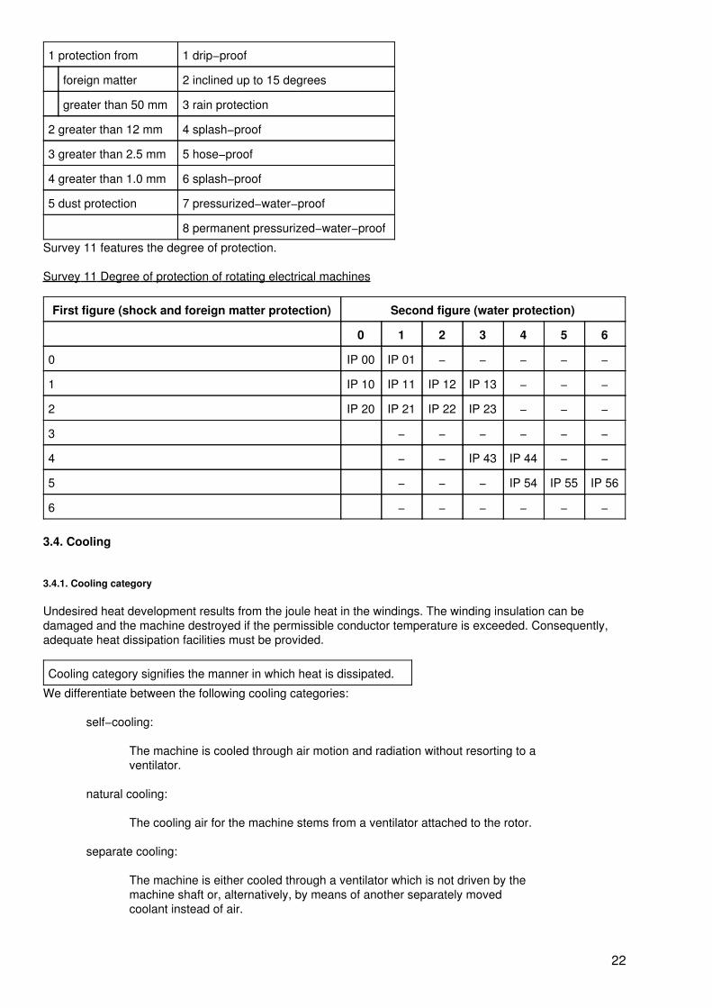
An abbreviation has been adopted for designating the degree of protection:
The abbreviation features:
The arrangement of the numerals for contact and foreign body protection along with the numerals pertainingto water protection have been set out in Survey 10.
Survey 10 Protection grade characteristics
1. Figure (shock andforeign matter
protection)
2. Figure (water protection)
0 unprotected 0 unprotected
21
1 protection from 1 drip−proof
foreign matter 2 inclined up to 15 degrees
greater than 50 mm 3 rain protection
2 greater than 12 mm 4 splash−proof
3 greater than 2.5 mm 5 hose−proof
4 greater than 1.0 mm 6 splash−proof
5 dust protection 7 pressurized−water−proof
8 permanent pressurized−water−proof
Survey 11 features the degree of protection.
Survey 11 Degree of protection of rotating electrical machines
First figure (shock and foreign matter protection) Second figure (water protection)
0 1 2 3 4 5 6
0 IP 00 IP 01 − − − − −
1 IP 10 IP 11 IP 12 IP 13 − − −
2 IP 20 IP 21 IP 22 IP 23 − − −
3 − − − − − −
4 − − IP 43 IP 44 − −
5 − − − IP 54 IP 55 IP 56
6 − − − − − −
3.4. Cooling
3.4.1. Cooling category
Undesired heat development results from the joule heat in the windings. The winding insulation can bedamaged and the machine destroyed if the permissible conductor temperature is exceeded. Consequently,adequate heat dissipation facilities must be provided.
Cooling category signifies the manner in which heat is dissipated.
We differentiate between the following cooling categories:
self−cooling:
The machine is cooled through air motion and radiation without resorting to aventilator.
natural cooling:
The cooling air for the machine stems from a ventilator attached to the rotor.
separate cooling:
The machine is either cooled through a ventilator which is not driven by themachine shaft or, alternatively, by means of another separately movedcoolant instead of air.
22
3.4.2. Cooling category designation
The coolant category designation indicates:
Type of coolantNature of the cooling cycleMethod of the coolant circulation
Designation:
1. Code letters of the cooling IC2. Type of coolant
Gases air A
hydrogen H
nitrogen N
carbon dioxide C
Liquids water W
oil U
(Where air only is used for cooling the letter "A" can be dropped.)
3. Cooling cycle arrangement (1st index)
4. Method of coolant circulation (2nd index)
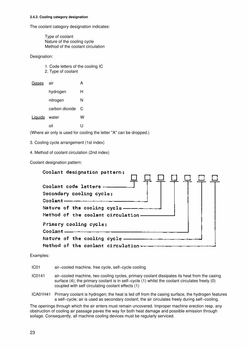
Coolant designation pattern:
Examples:
IC01 air−cooled machine, free cycle, self−cycle cooling
IC0141 air−cooled machine, two cooling cycles, primary coolant dissipates its heat from the casingsurface (4); the primary coolant is in self−cycle (1) whilst the coolant circulates freely (0)coupled with self circulating coolant effects (1)
ICA01H41 Primary coolant is hydrogen; the heat is led off from the casing surface, the hydrogen featuresa self−cycle; air is used as secondary coolant; the air circulates freely during self−cooling.
The openings through which the air enters must remain uncovered. Improper machine erection resp. anyobstruction of cooling air passage paves the way for both heat damage and possible emission throughsoilage. Consequently, all machine cooling devices must be regularly serviced.
23
3.5. Mode of operation
3.5.1. Definition
Operating an electric motor always gives rise to undesirable energy conversion. This in turn leads to heatingup which, above all, strains the winding insulations. The service life of a machine is decisively influenced by itsinside temperature. Thermal overloading can engender operational disturbances. Estimates indicate that atemperature increase of 8K reduces machine life by 50 per cent. Heating up results first and foremost throughenergy passage in the windings. The designation W = I2 · R · t shows that the conversion into heat and therelated temperature rise are determined by the current flow and its duration. Temporary overloading ispermissible as, due to thermal inertia, the temperature increase remains insignificant. A torque increase forthe work unit, respectively a mass inertia when starting or braking give rise to greater losses in the motorthrough the flow of higher starting or braking currents. Load, starting and braking thus exert an influence onthe degree of heating up. Consequently, for reasons related to thermal load, electric motors must be alignedto the load rhythm of the work unit.
Mode of operation relates to the nature and sequence pattern, equally the duration of standstill and idlingtimes, also to the nominal load of electrical machines.
3.5.2. Operational mode designation
Following abbreviations have been stipulated:
S1 permanent operationS2 short−term operationS3 intermittent operation with starting or braking influencesS4 intermittent operation with starting influence on temperatureS5 intermittent operation with starting and electric braking influence on the temperatureS6 continuous operation with intermittent loadingS7 uninterrupted operation with starting and electric brakingS8 uninterrupted operation at differing speeds
3.5.3. Frequent nominal cycle ratings
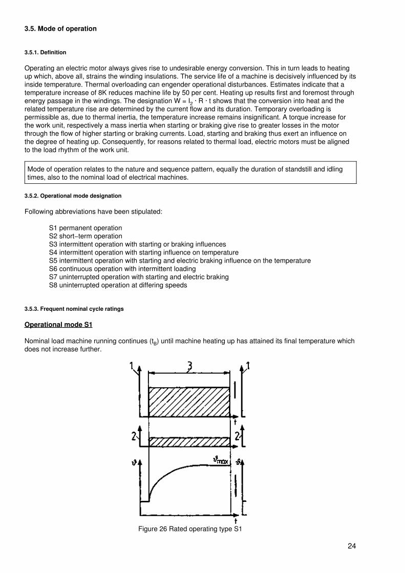
Operational mode S1
Nominal load machine running continues (tB) until machine heating up has attained its final temperature whichdoes not increase further.
Figure 26 Rated operating type S1
24
Legend as for Figure 28
The final temperature shall not exceed the limit temperature heat resistance category of the machine.
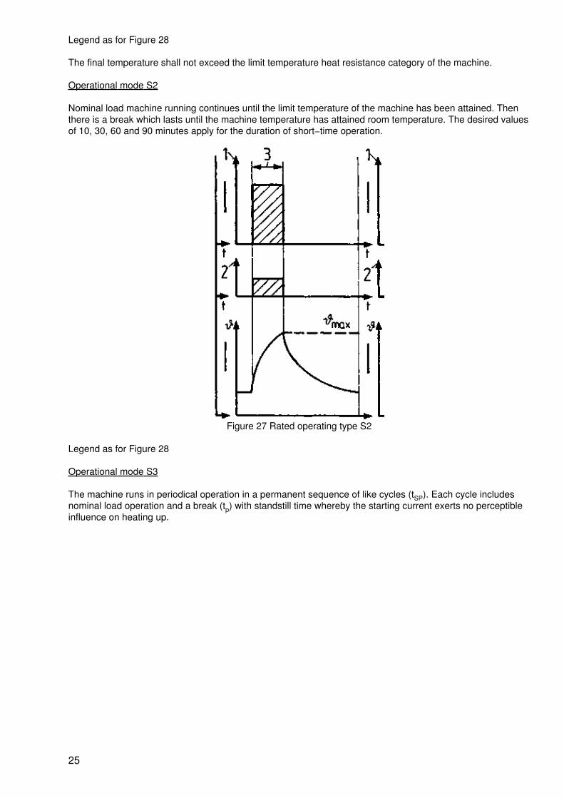
Operational mode S2
Nominal load machine running continues until the limit temperature of the machine has been attained. Thenthere is a break which lasts until the machine temperature has attained room temperature. The desired valuesof 10, 30, 60 and 90 minutes apply for the duration of short−time operation.
Figure 27 Rated operating type S2
Legend as for Figure 28
Operational mode S3
The machine runs in periodical operation in a permanent sequence of like cycles (tSP). Each cycle includesnominal load operation and a break (tp) with standstill time whereby the starting current exerts no perceptibleinfluence on heating up.
25
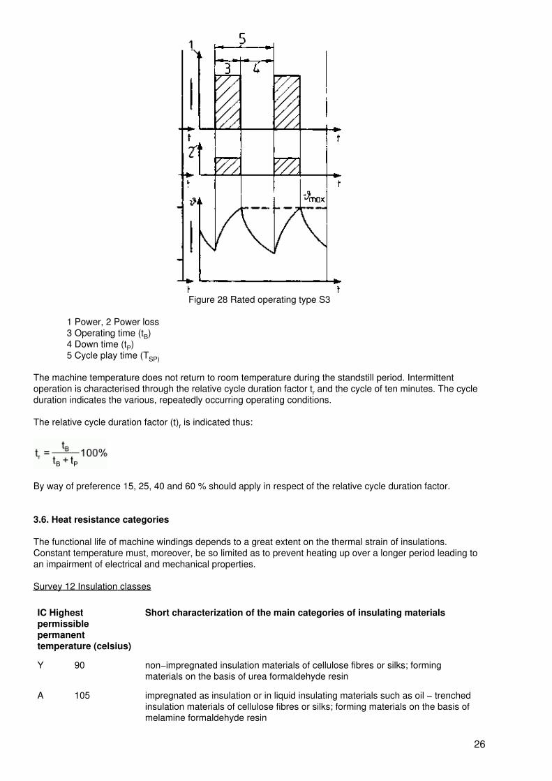
Figure 28 Rated operating type S3
1 Power, 2 Power loss3 Operating time (tB)4 Down time (tP)5 Cycle play time (TSP)
The machine temperature does not return to room temperature during the standstill period. Intermittentoperation is characterised through the relative cycle duration factor tr and the cycle of ten minutes. The cycleduration indicates the various, repeatedly occurring operating conditions.
The relative cycle duration factor (t)r is indicated thus:
By way of preference 15, 25, 40 and 60 % should apply in respect of the relative cycle duration factor.
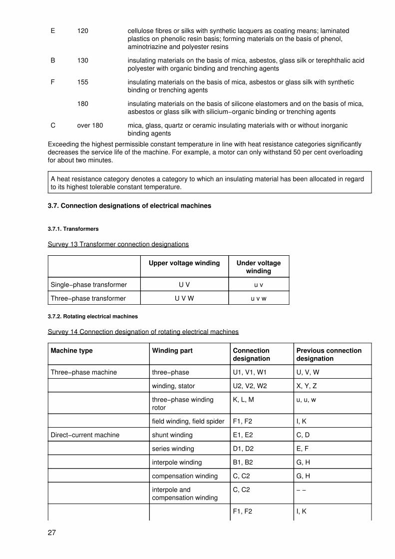
3.6. Heat resistance categories
The functional life of machine windings depends to a great extent on the thermal strain of insulations.Constant temperature must, moreover, be so limited as to prevent heating up over a longer period leading toan impairment of electrical and mechanical properties.
Survey 12 Insulation classes
IC Highestpermissiblepermanenttemperature (celsius)
Short characterization of the main categories of insulating materials
Y 90 non−impregnated insulation materials of cellulose fibres or silks; formingmaterials on the basis of urea formaldehyde resin
A 105 impregnated as insulation or in liquid insulating materials such as oil − trenchedinsulation materials of cellulose fibres or silks; forming materials on the basis ofmelamine formaldehyde resin
26
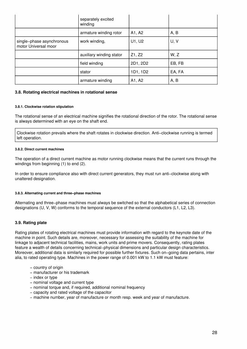
E 120 cellulose fibres or silks with synthetic lacquers as coating means; laminatedplastics on phenolic resin basis; forming materials on the basis of phenol,aminotriazine and polyester resins
B 130 insulating materials on the basis of mica, asbestos, glass silk or terephthalic acidpolyester with organic binding and trenching agents
F 155 insulating materials on the basis of mica, asbestos or glass silk with syntheticbinding or trenching agents
180 insulating materials on the basis of silicone elastomers and on the basis of mica,asbestos or glass silk with silicium−organic binding or trenching agents
C over 180 mica, glass, quartz or ceramic insulating materials with or without inorganicbinding agents
Exceeding the highest permissible constant temperature in line with heat resistance categories significantlydecreases the service life of the machine. For example, a motor can only withstand 50 per cent overloadingfor about two minutes.
A heat resistance category denotes a category to which an insulating material has been allocated in regardto its highest tolerable constant temperature.
3.7. Connection designations of electrical machines
3.7.1. Transformers
Survey 13 Transformer connection designations
Upper voltage winding Under voltagewinding
Single−phase transformer U V u v
Three−phase transformer U V W u v w
3.7.2. Rotating electrical machines
Survey 14 Connection designation of rotating electrical machines
Machine type Winding part Connectiondesignation
Previous connectiondesignation
Three−phase machine three−phase U1, V1, W1 U, V, W
winding, stator U2, V2, W2 X, Y, Z
three−phase windingrotor
K, L, M u, u, w
field winding, field spider F1, F2 I, K
Direct−current machine shunt winding E1, E2 C, D
series winding D1, D2 E, F
interpole winding B1, B2 G, H
compensation winding C, C2 G, H
interpole andcompensation winding
C, C2 − −
F1, F2 I, K
27
separately excitedwinding
armature winding rotor A1, A2 A, B
single−phase asynchronousmotor Universal moor
work winding, U1, U2 U, V
auxiliary winding stator Z1, Z2 W, Z
field winding 2D1, 2D2 EB, FB
stator 1D1, 1D2 EA, FA
armature winding A1, A2 A, B
3.8. Rotating electrical machines in rotational sense
3.8.1. Clockwise rotation stipulation
The rotational sense of an electrical machine signifies the rotational direction of the rotor. The rotational senseis always determined with an eye on the shaft end.
Clockwise rotation prevails where the shaft rotates in clockwise direction. Anti−clockwise running is termedleft operation.
3.8.2. Direct current machines
The operation of a direct current machine as motor running clockwise means that the current runs through thewindings from beginning (1) to end (2).
In order to ensure compliance also with direct current generators, they must run anti−clockwise along withunaltered designation.
3.8.3. Alternating current and three−phase machines
Alternating and three−phase machines must always be switched so that the alphabetical series of connectiondesignations (U, V, W) conforms to the temporal sequence of the external conductors (L1, L2, L3).
3.9. Rating plate
Rating plates of rotating electrical machines must provide information with regard to the keynote date of themachine in point. Such details are, moreover, necessary for assessing the suitability of the machine forlinkage to adjacent technical facilities, mains, work units and prime movers. Consequently, rating platesfeature a wealth of details concerning technical−physical dimensions and particular design characteristics.Moreover, additional data is similarly required for possible further fixtures. Such on−going data pertains, interalia, to rated operating type. Machines in the power range of 0.001 kW to 1.1 kW must feature:
− country of origin− manufacturer or his trademark− index or type− nominal voltage and current type− nominal torque and, if required, additional nominal frequency− capacity and rated voltage of the capacitor− machine number, year of manufacture or month resp. week and year of manufacture.
28
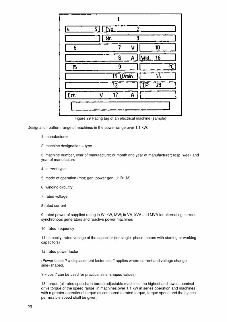
Figure 29 Rating tag of an electrical machine (sample)
Designation pattern range of machines in the power range over 1.1 kW:
1. manufacturer
2. machine designation − type
3. machine number, year of manufacture; or month and year of manufacturer; resp. week andyear of manufacture
4. current type
5. mode of operation (mot; gen; power gen; U; B1 M)
6. winding circuitry
7. rated voltage
8 rated current
9. rated power of supplied rating in W, kW, MW; in VA, kVA and MVA for alternating currentsynchronous generators and reactive power machines
10. rated frequency
11. capacity, rated voltage of the capacitor (for single−phase motors with starting or workingcapacitors)
12. rated power factor
(Power factor ? = displacement factor cos ? applies where current and voltage changesine−shaped.
? = cos ? can be used for practical sine−shaped values)
13. torque (all rated speeds; in torque adjustable machines the highest and lowest nominaldrive torque of the speed range; in machines over 1.1 kW in series operation and machineswith a greater operational torque as compared to rated torque, torque speed and the highestpermissible speed shall be given)
29
14. rotational direction (only if required)
15. rated operational mode (apart from S1)
16. insulation class
17. Rated exciting current; rated exciting voltage (exc....A; esc....V)
18. nominal stillstand voltage between the slip−rings given rated operation (Lf...V)
19. mass
20. number of standard
21. quality sign
22. design
23. degree of protection
Questions for repetition and control
1. What characterises the design of a motor?
2. Which degree of protection must be selected for a motor positioned in moist surroundings?
3. What does operational mode S1 denote?
4. How is clockwise running stipulated for electric motors?
4. Synchronous machines
4.1. Operating principles
4.1.1. Synchronous generator
Alternating−voltage generator
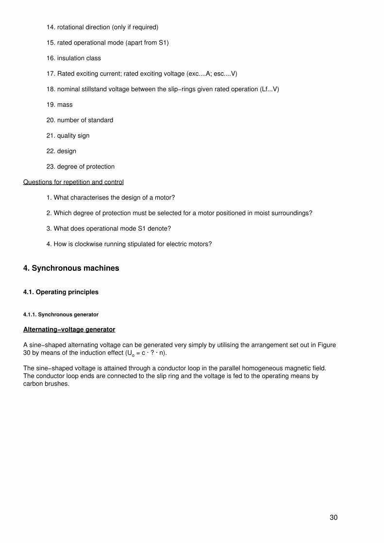
A sine−shaped alternating voltage can be generated very simply by utilising the arrangement set out in Figure30 by means of the induction effect (Uo = c · ? · n).
The sine−shaped voltage is attained through a conductor loop in the parallel homogeneous magnetic field.The conductor loop ends are connected to the slip ring and the voltage is fed to the operating means bycarbon brushes.
30
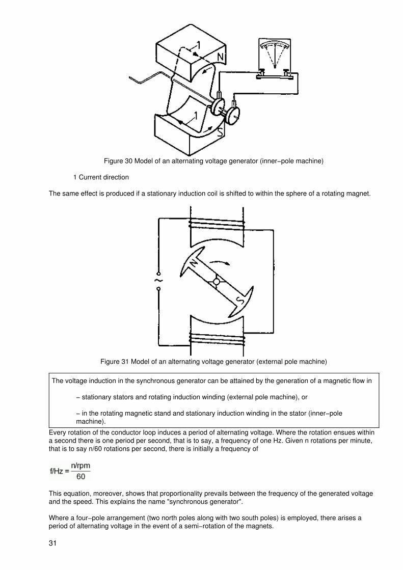
Figure 30 Model of an alternating voltage generator (inner−pole machine)
1 Current direction
The same effect is produced if a stationary induction coil is shifted to within the sphere of a rotating magnet.
Figure 31 Model of an alternating voltage generator (external pole machine)
The voltage induction in the synchronous generator can be attained by the generation of a magnetic flow in
− stationary stators and rotating induction winding (external pole machine), or
− in the rotating magnetic stand and stationary induction winding in the stator (inner−polemachine).
Every rotation of the conductor loop induces a period of alternating voltage. Where the rotation ensues withina second there is one period per second, that is to say, a frequency of one Hz. Given n rotations per minute,that is to say n/60 rotations per second, there is initially a frequency of
This equation, moreover, shows that proportionality prevails between the frequency of the generated voltageand the speed. This explains the name "synchronous generator".
Where a four−pole arrangement (two north poles along with two south poles) is employed, there arises aperiod of alternating voltage in the event of a semi−rotation of the magnets.
31
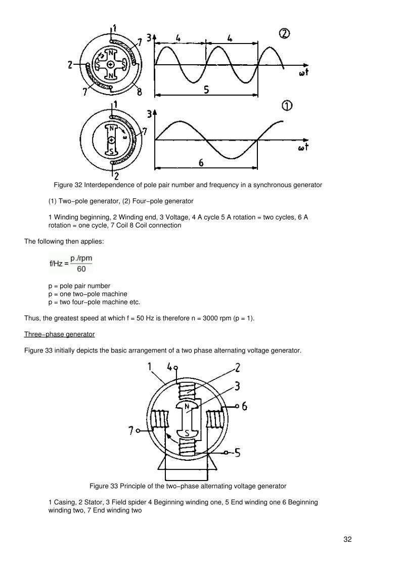
Figure 32 Interdependence of pole pair number and frequency in a synchronous generator
(1) Two−pole generator, (2) Four−pole generator
1 Winding beginning, 2 Winding end, 3 Voltage, 4 A cycle 5 A rotation = two cycles, 6 Arotation = one cycle, 7 Coil 8 Coil connection
The following then applies:
p = pole pair numberp = one two−pole machinep = two four−pole machine etc.
Thus, the greatest speed at which f = 50 Hz is therefore n = 3000 rpm (p = 1).
Three−phase generator
Figure 33 initially depicts the basic arrangement of a two phase alternating voltage generator.
Figure 33 Principle of the two−phase alternating voltage generator
1 Casing, 2 Stator, 3 Field spider 4 Beginning winding one, 5 End winding one 6 Beginningwinding two, 7 End winding two
32
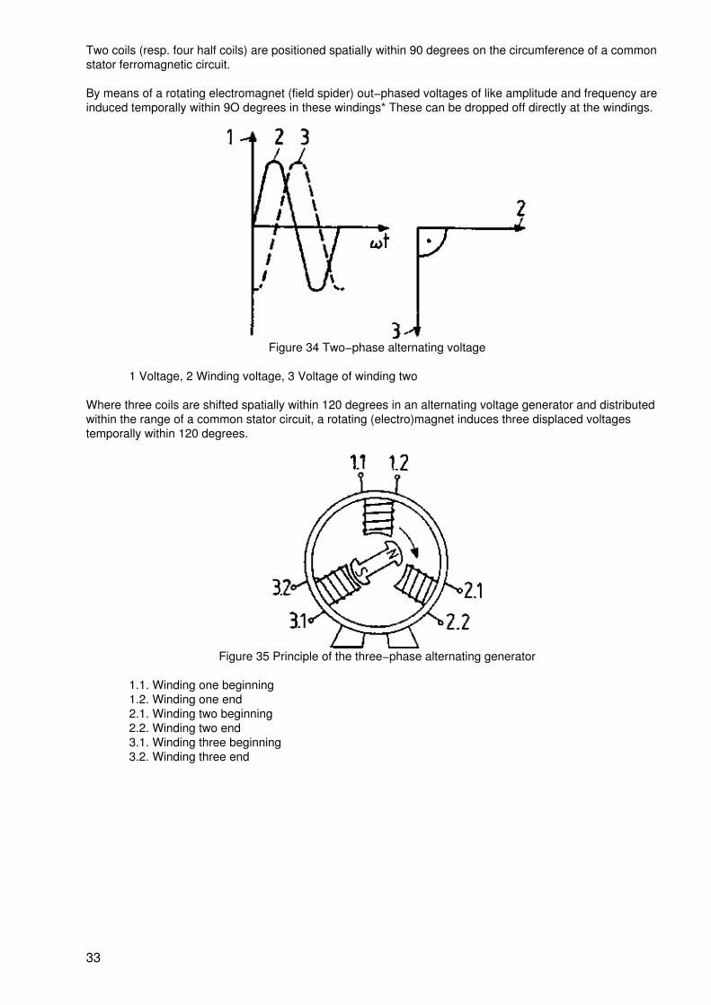
Two coils (resp. four half coils) are positioned spatially within 90 degrees on the circumference of a commonstator ferromagnetic circuit.
By means of a rotating electromagnet (field spider) out−phased voltages of like amplitude and frequency areinduced temporally within 9O degrees in these windings* These can be dropped off directly at the windings.
Figure 34 Two−phase alternating voltage
1 Voltage, 2 Winding voltage, 3 Voltage of winding two
Where three coils are shifted spatially within 120 degrees in an alternating voltage generator and distributedwithin the range of a common stator circuit, a rotating (electro)magnet induces three displaced voltagestemporally within 120 degrees.
Figure 35 Principle of the three−phase alternating generator
1.1. Winding one beginning1.2. Winding one end2.1. Winding two beginning2.2. Winding two end3.1. Winding three beginning3.2. Winding three end
33
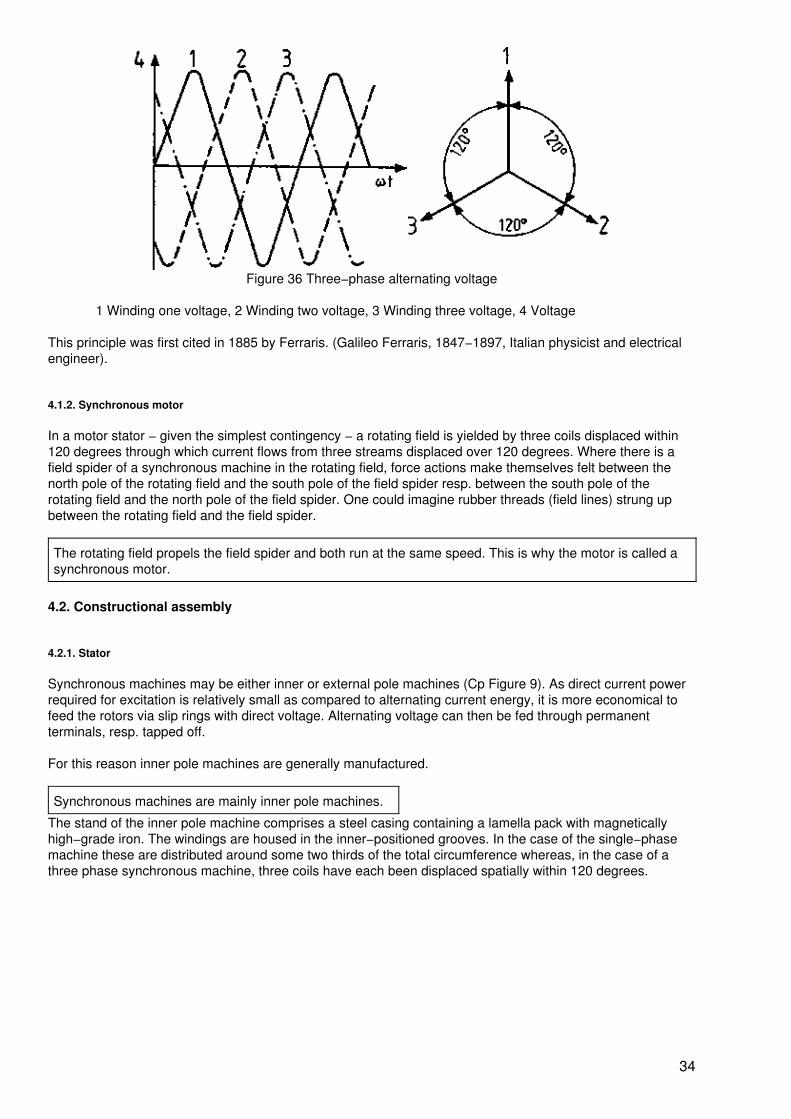
Figure 36 Three−phase alternating voltage
1 Winding one voltage, 2 Winding two voltage, 3 Winding three voltage, 4 Voltage
This principle was first cited in 1885 by Ferraris. (Galileo Ferraris, 1847−1897, Italian physicist and electricalengineer).
4.1.2. Synchronous motor
In a motor stator − given the simplest contingency − a rotating field is yielded by three coils displaced within120 degrees through which current flows from three streams displaced over 120 degrees. Where there is afield spider of a synchronous machine in the rotating field, force actions make themselves felt between thenorth pole of the rotating field and the south pole of the field spider resp. between the south pole of therotating field and the north pole of the field spider. One could imagine rubber threads (field lines) strung upbetween the rotating field and the field spider.
The rotating field propels the field spider and both run at the same speed. This is why the motor is called asynchronous motor.
4.2. Constructional assembly
4.2.1. Stator
Synchronous machines may be either inner or external pole machines (Cp Figure 9). As direct current powerrequired for excitation is relatively small as compared to alternating current energy, it is more economical tofeed the rotors via slip rings with direct voltage. Alternating voltage can then be fed through permanentterminals, resp. tapped off.
For this reason inner pole machines are generally manufactured.
Synchronous machines are mainly inner pole machines.
The stand of the inner pole machine comprises a steel casing containing a lamella pack with magneticallyhigh−grade iron. The windings are housed in the inner−positioned grooves. In the case of the single−phasemachine these are distributed around some two thirds of the total circumference whereas, in the case of athree phase synchronous machine, three coils have each been displaced spatially within 120 degrees.
34
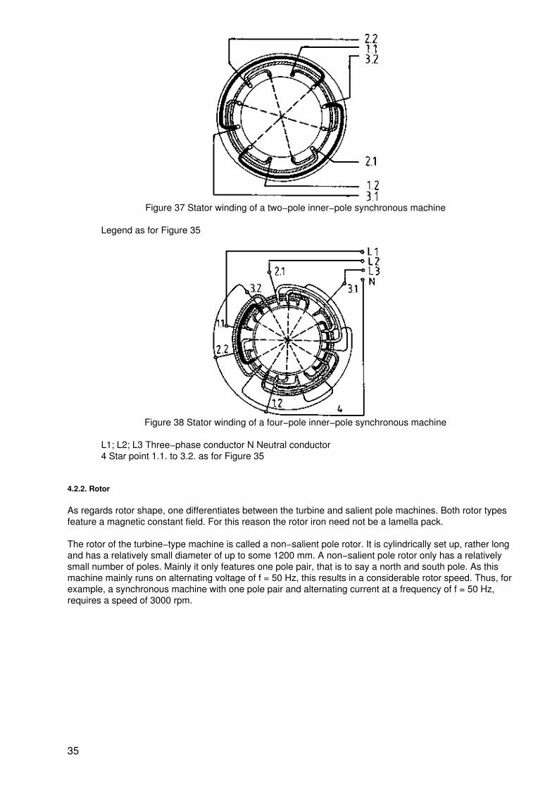
Figure 37 Stator winding of a two−pole inner−pole synchronous machine
Legend as for Figure 35
Figure 38 Stator winding of a four−pole inner−pole synchronous machine
L1; L2; L3 Three−phase conductor N Neutral conductor4 Star point 1.1. to 3.2. as for Figure 35
4.2.2. Rotor
As regards rotor shape, one differentiates between the turbine and salient pole machines. Both rotor typesfeature a magnetic constant field. For this reason the rotor iron need not be a lamella pack.
The rotor of the turbine−type machine is called a non−salient pole rotor. It is cylindrically set up, rather longand has a relatively small diameter of up to some 1200 mm. A non−salient pole rotor only has a relativelysmall number of poles. Mainly it only features one pole pair, that is to say a north and south pole. As thismachine mainly runs on alternating voltage of f = 50 Hz, this results in a considerable rotor speed. Thus, forexample, a synchronous machine with one pole pair and alternating current at a frequency of f = 50 Hz,requires a speed of 3000 rpm.
35
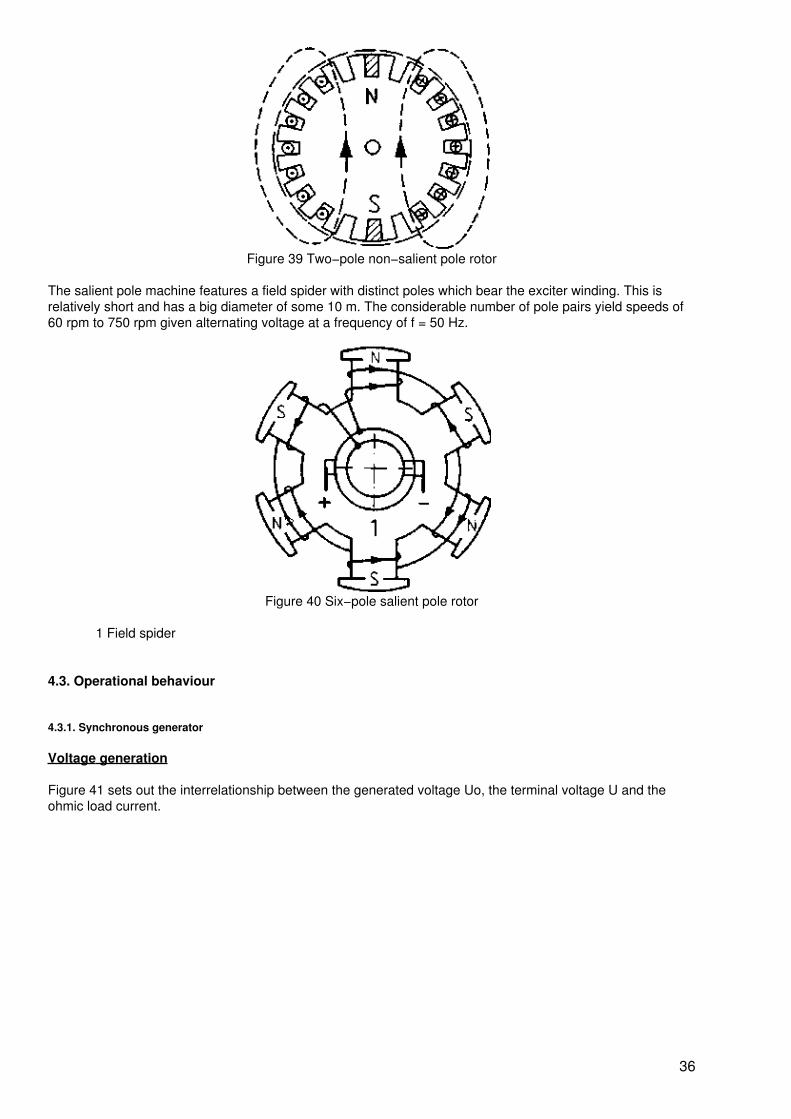
Figure 39 Two−pole non−salient pole rotor
The salient pole machine features a field spider with distinct poles which bear the exciter winding. This isrelatively short and has a big diameter of some 10 m. The considerable number of pole pairs yield speeds of60 rpm to 750 rpm given alternating voltage at a frequency of f = 50 Hz.
Figure 40 Six−pole salient pole rotor
1 Field spider
4.3. Operational behaviour
4.3.1. Synchronous generator
Voltage generation
Figure 41 sets out the interrelationship between the generated voltage Uo, the terminal voltage U and theohmic load current.
36
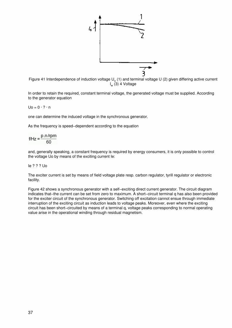
Figure 41 Interdependence of induction voltage Uo (1) and terminal voltage U (2) given differing active currentIw (3) 4 Voltage
In order to retain the required, constant terminal voltage, the generated voltage must be supplied. Accordingto the generator equation
Uo = 0 · ? · n
one can determine the induced voltage in the synchronous generator.
As the frequency is speed−dependent according to the equation
and, generally speaking, a constant frequency is required by energy consumers, it is only possible to controlthe voltage Uo by means of the exciting current Ie:
Ie ? ? ? Uo
The exciter current is set by means of field voltage plate resp. carbon regulator, tyrill regulator or electronicfacility.
Figure 42 shows a synchronous generator with a self−exciting direct current generator. The circuit diagramindicates that−the current can be set from zero to maximum. A short−circuit terminal q has also been providedfor the exciter circuit of the synchronous generator. Switching off excitation cannot ensue through immediateinterruption of the exciting circuit as induction leads to voltage peaks. Moreover, even where the excitingcircuit has been short−circuited by means of a terminal q, voltage peaks corresponding to normal operatingvalue arise in the operational winding through residual magnetism.
37
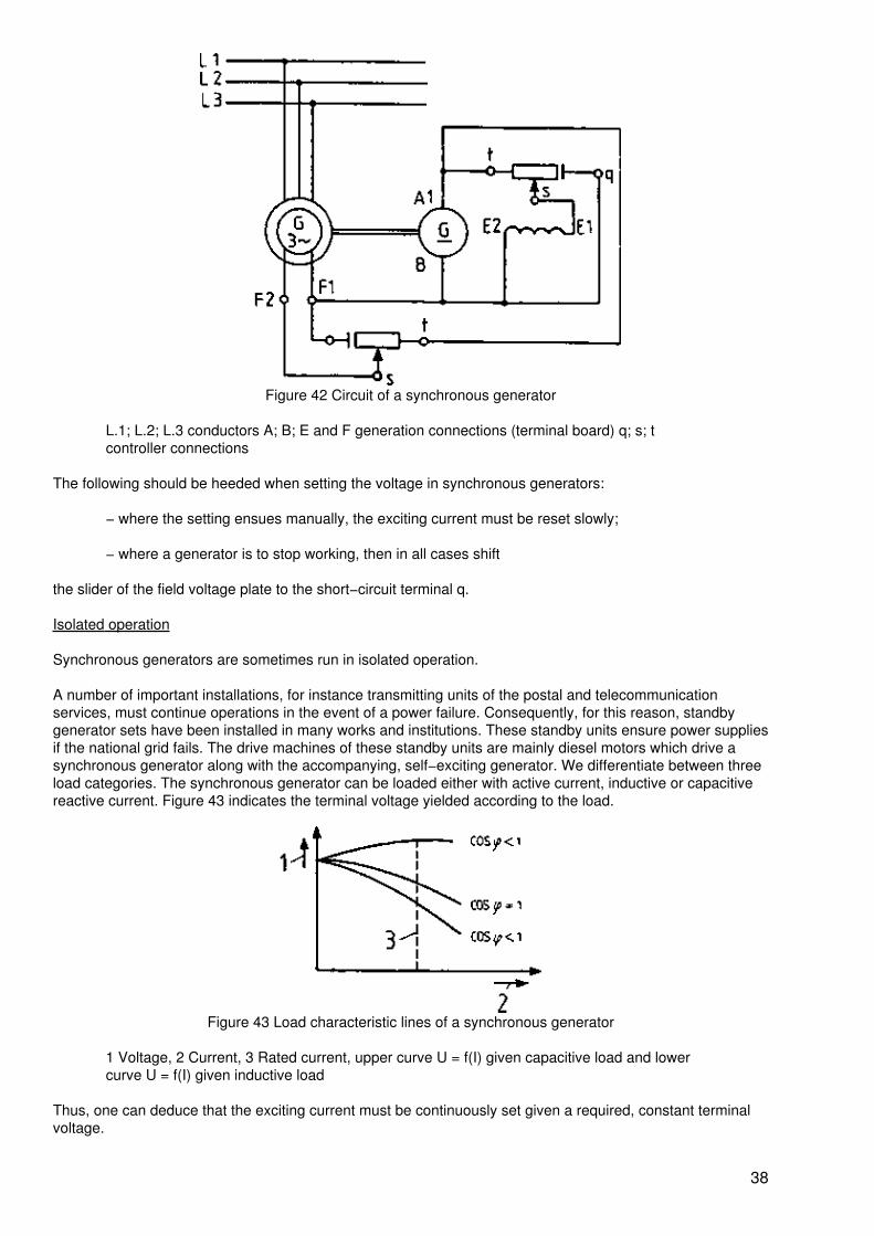
Figure 42 Circuit of a synchronous generator
L.1; L.2; L.3 conductors A; B; E and F generation connections (terminal board) q; s; tcontroller connections
The following should be heeded when setting the voltage in synchronous generators:
− where the setting ensues manually, the exciting current must be reset slowly;
− where a generator is to stop working, then in all cases shift
the slider of the field voltage plate to the short−circuit terminal q.
Isolated operation
Synchronous generators are sometimes run in isolated operation.
A number of important installations, for instance transmitting units of the postal and telecommunicationservices, must continue operations in the event of a power failure. Consequently, for this reason, standbygenerator sets have been installed in many works and institutions. These standby units ensure power suppliesif the national grid fails. The drive machines of these standby units are mainly diesel motors which drive asynchronous generator along with the accompanying, self−exciting generator. We differentiate between threeload categories. The synchronous generator can be loaded either with active current, inductive or capacitivereactive current. Figure 43 indicates the terminal voltage yielded according to the load.
Figure 43 Load characteristic lines of a synchronous generator
1 Voltage, 2 Current, 3 Rated current, upper curve U = f(I) given capacitive load and lowercurve U = f(I) given inductive load
Thus, one can deduce that the exciting current must be continuously set given a required, constant terminalvoltage.
38
Rigid network operation
Where a synchronous generator feeds power to a network whose voltage also remains constant in the face ofload differences, then one refers to a rigid network machine. Generally speaking several generators operatewithin such a network, for instance, as is customary for energy generation in power stations. One also refersto parallel or compound operation. Where several or merely one generator works within the network, then thefollowing must be heeded when switching on the second resp. subsequent generator:
− The frequency of the generator to be added must conform with the network frequency!
− Network voltage and generator voltage must feature identical values. The phase position ofboth voltages must concur.
− The correct phase sequence L1−L2−L3 of the network and the generators to be switchedon must be checked!
Special measuring devices resp. circuits have been devised to ensure that these conditions are adhered to or,as one says, that the generator to be switched on is "synchronized".
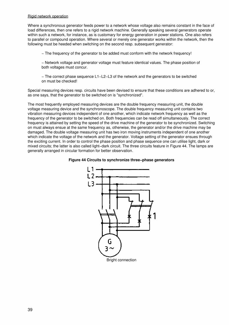
The most frequently employed measuring devices are the double frequency measuring unit, the doublevoltage measuring device and the synchronoscope. The double frequency measuring unit contains twovibration measuring devices independent of one another, which indicate network frequency as well as thefrequency of the generator to be switched on. Both frequencies can be read off simultaneously. The correctfrequency is attained by setting the speed of the drive machine of the generator to be synchronized. Switchingon must always ensue at the same frequency as, otherwise, the generator and/or the drive machine may bedamaged. The double voltage measuring unit has two iron moving instruments independent of one anotherwhich indicate the voltage of the network and the generator. Voltage setting of the generator ensues throughthe exciting current. In order to control the phase position and phase sequence one can utilise light, dark ormixed circuits; the latter is also called light−dark circuit. The three circuits feature in Figure 44. The lamps aregenerally arranged in circular formation for better observation.
Figure 44 Circuits to synchronize three−phase generators
Bright connection
39
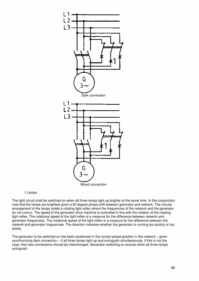
Dark connection
Mixed connection
1 Lamps
The light circuit shall be switched on when all three lamps light up brightly at the same time. In this conjunctionnote that the lamps are brightest given a 60 degree phase shift between generator and network. The circulararrangement of the lamps yields a rotating light reflex where the frequencies of the network and the generatordo not concur. The speed of the generator drive machine is controlled in line with the rotation of the rotatinglight reflex. The rotational speed of the light reflex is a measure for the difference between network andgenerator frequencies. The rotational speed of the light reflex is a measure for the difference between thenetwork and generator frequencies. The direction indicates whether the generator is running too quickly or tooslowly.
The generator to be switched on has been positioned in the correct phase position in the network − givensynchronizing dark connection − if all three lamps light up and extinguish simultaneously. If this is not thecase, then two connections should be interchanged. Generator switching on ensues when all three lampsextinguish.
40
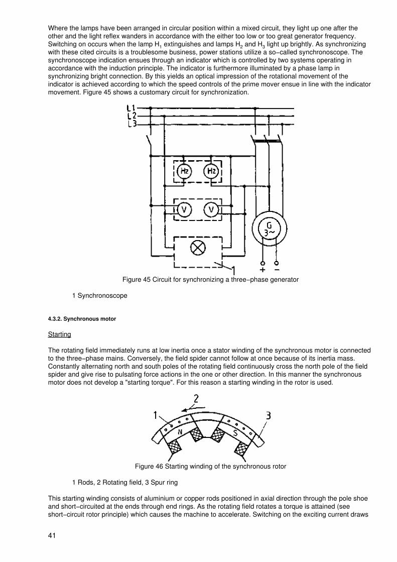
Where the lamps have been arranged in circular position within a mixed circuit, they light up one after theother and the light reflex wanders in accordance with the either too low or too great generator frequency.Switching on occurs when the lamp H1 extinguishes and lamps H2 and H3 light up brightly. As synchronizingwith these cited circuits is a troublesome business, power stations utilize a so−called synchronoscope. Thesynchronoscope indication ensues through an indicator which is controlled by two systems operating inaccordance with the induction principle. The indicator is furthermore illuminated by a phase lamp insynchronizing bright connection. By this yields an optical impression of the rotational movement of theindicator is achieved according to which the speed controls of the prime mover ensue in line with the indicatormovement. Figure 45 shows a customary circuit for synchronization.
Figure 45 Circuit for synchronizing a three−phase generator
1 Synchronoscope
4.3.2. Synchronous motor
Starting
The rotating field immediately runs at low inertia once a stator winding of the synchronous motor is connectedto the three−phase mains. Conversely, the field spider cannot follow at once because of its inertia mass.Constantly alternating north and south poles of the rotating field continuously cross the north pole of the fieldspider and give rise to pulsating force actions in the one or other direction. In this manner the synchronousmotor does not develop a "starting torque". For this reason a starting winding in the rotor is used.
Figure 46 Starting winding of the synchronous rotor
1 Rods, 2 Rotating field, 3 Spur ring
This starting winding consists of aluminium or copper rods positioned in axial direction through the pole shoeand short−circuited at the ends through end rings. As the rotating field rotates a torque is attained (seeshort−circuit rotor principle) which causes the machine to accelerate. Switching on the exciting current draws
41
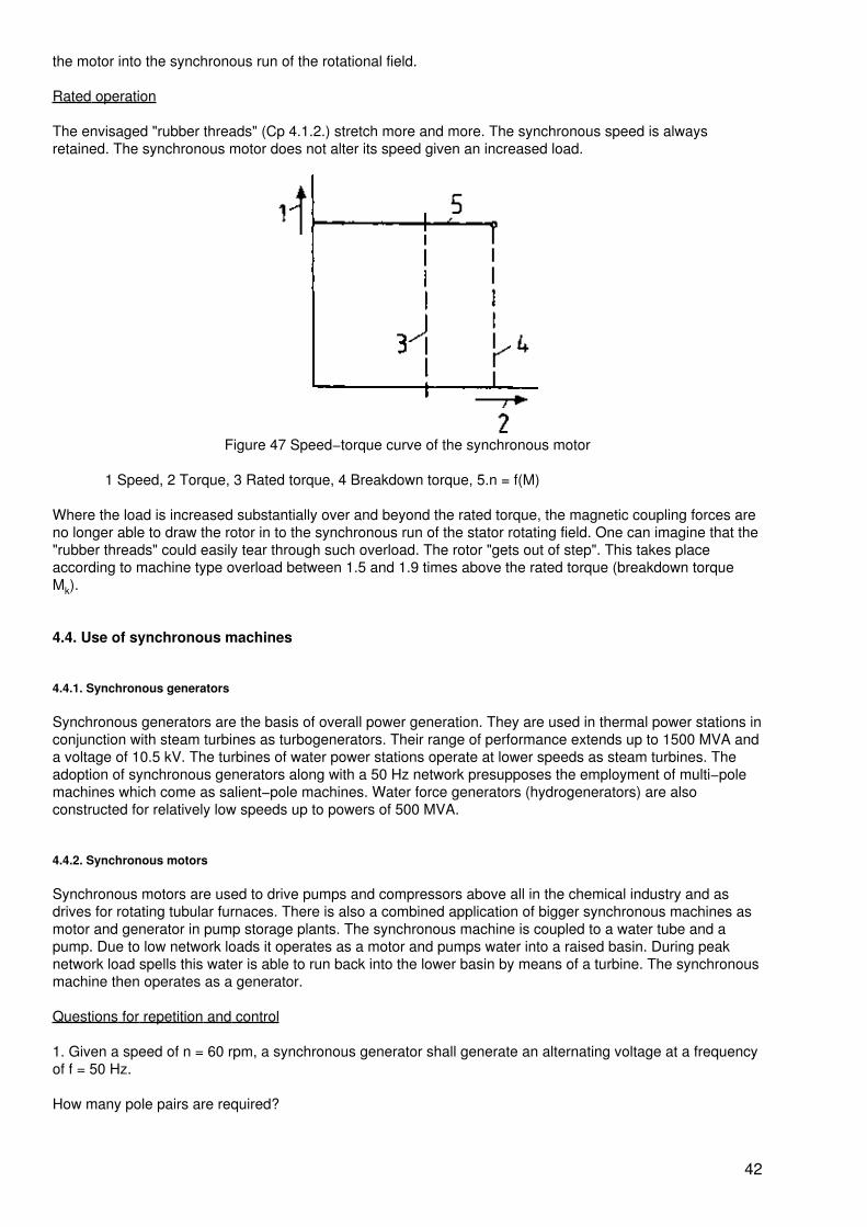
the motor into the synchronous run of the rotational field.
Rated operation
The envisaged "rubber threads" (Cp 4.1.2.) stretch more and more. The synchronous speed is alwaysretained. The synchronous motor does not alter its speed given an increased load.
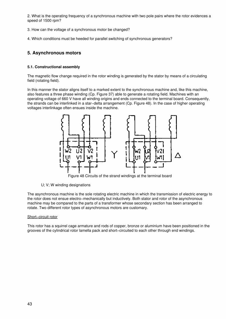
Figure 47 Speed−torque curve of the synchronous motor
1 Speed, 2 Torque, 3 Rated torque, 4 Breakdown torque, 5.n = f(M)
Where the load is increased substantially over and beyond the rated torque, the magnetic coupling forces areno longer able to draw the rotor in to the synchronous run of the stator rotating field. One can imagine that the"rubber threads" could easily tear through such overload. The rotor "gets out of step". This takes placeaccording to machine type overload between 1.5 and 1.9 times above the rated torque (breakdown torqueMk).
4.4. Use of synchronous machines
4.4.1. Synchronous generators
Synchronous generators are the basis of overall power generation. They are used in thermal power stations inconjunction with steam turbines as turbogenerators. Their range of performance extends up to 1500 MVA anda voltage of 10.5 kV. The turbines of water power stations operate at lower speeds as steam turbines. Theadoption of synchronous generators along with a 50 Hz network presupposes the employment of multi−polemachines which come as salient−pole machines. Water force generators (hydrogenerators) are alsoconstructed for relatively low speeds up to powers of 500 MVA.
4.4.2. Synchronous motors
Synchronous motors are used to drive pumps and compressors above all in the chemical industry and asdrives for rotating tubular furnaces. There is also a combined application of bigger synchronous machines asmotor and generator in pump storage plants. The synchronous machine is coupled to a water tube and apump. Due to low network loads it operates as a motor and pumps water into a raised basin. During peaknetwork load spells this water is able to run back into the lower basin by means of a turbine. The synchronousmachine then operates as a generator.
Questions for repetition and control
1. Given a speed of n = 60 rpm, a synchronous generator shall generate an alternating voltage at a frequencyof f = 50 Hz.
How many pole pairs are required?
42
2. What is the operating frequency of a synchronous machine with two pole pairs where the rotor evidences aspeed of 1500 rpm?
3. How can the voltage of a synchronous motor be changed?
4. Which conditions must be heeded for parallel switching of synchronous generators?
5. Asynchronous motors
5.1. Constructional assembly
The magnetic flow change required in the rotor winding is generated by the stator by means of a circulatingfield (rotating field).
In this manner the stator aligns itself to a marked extent to the synchronous machine and, like this machine,also features a three phase winding (Cp. Figure 37) able to generate a rotating field. Machines with anoperating voltage of 660 V have all winding origins and ends connected to the terminal board. Consequently,the strands can be interlinked in a star−delta arrangement (Cp. Figure 48). In the case of higher operatingvoltages interlinkage often ensues inside the machine.
Figure 48 Circuits of the strand windings at the terminal board
U; V; W winding designations
The asynchronous machine is the sole rotating electric machine in which the transmission of electric energy tothe rotor does not ensue electro−mechanically but inductively. Both stator and rotor of the asynchronousmachine may be compared to the parts of a transformer whose secondary section has been arranged torotate. Two different rotor types of asynchronous motors are customary.
Short−circuit rotor
This rotor has a squirrel cage armature and rods of copper, bronze or aluminium have been positioned in thegrooves of the cylindrical rotor lamella pack and short−circuited to each other through end windings.
43
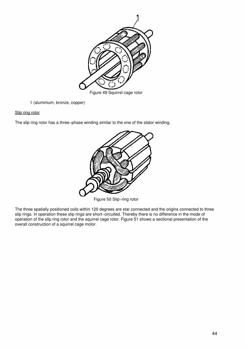
Figure 49 Squirrel cage rotor
1 (aluminium, bronze, copper)
Slip ring rotor
The slip ring rotor has a three−phase winding similar to the one of the stator winding.
Figure 50 Slip−ring rotor
The three spatially positioned coils within 120 degrees are star connected and the origins connected to threeslip rings. In operation these slip rings are short−circuited. Thereby there is no difference in the mode ofoperation of the slip ring rotor and the squirrel cage rotor. Figure 51 shows a sectional presentation of theoverall construction of a squirrel cage motor.
44
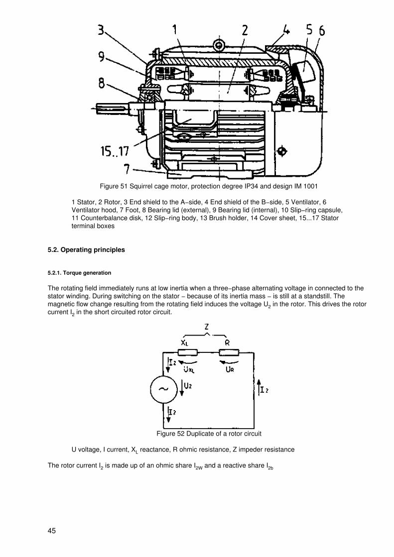
Figure 51 Squirrel cage motor, protection degree IP34 and design IM 1001
1 Stator, 2 Rotor, 3 End shield to the A−side, 4 End shield of the B−side, 5 Ventilator, 6Ventilator hood, 7 Foot, 8 Bearing lid (external), 9 Bearing lid (internal), 10 Slip−ring capsule,11 Counterbalance disk, 12 Slip−ring body, 13 Brush holder, 14 Cover sheet, 15...17 Statorterminal boxes
5.2. Operating principles
5.2.1. Torque generation
The rotating field immediately runs at low inertia when a three−phase alternating voltage in connected to thestator winding. During switching on the stator − because of its inertia mass − is still at a standstill. Themagnetic flow change resulting from the rotating field induces the voltage U2 in the rotor. This drives the rotorcurrent I2 in the short circuited rotor circuit.
Figure 52 Duplicate of a rotor circuit
U voltage, I current, XL reactance, R ohmic resistance, Z impeder resistance
The rotor current I2 is made up of an ohmic share I2W and a reactive share I2b
45
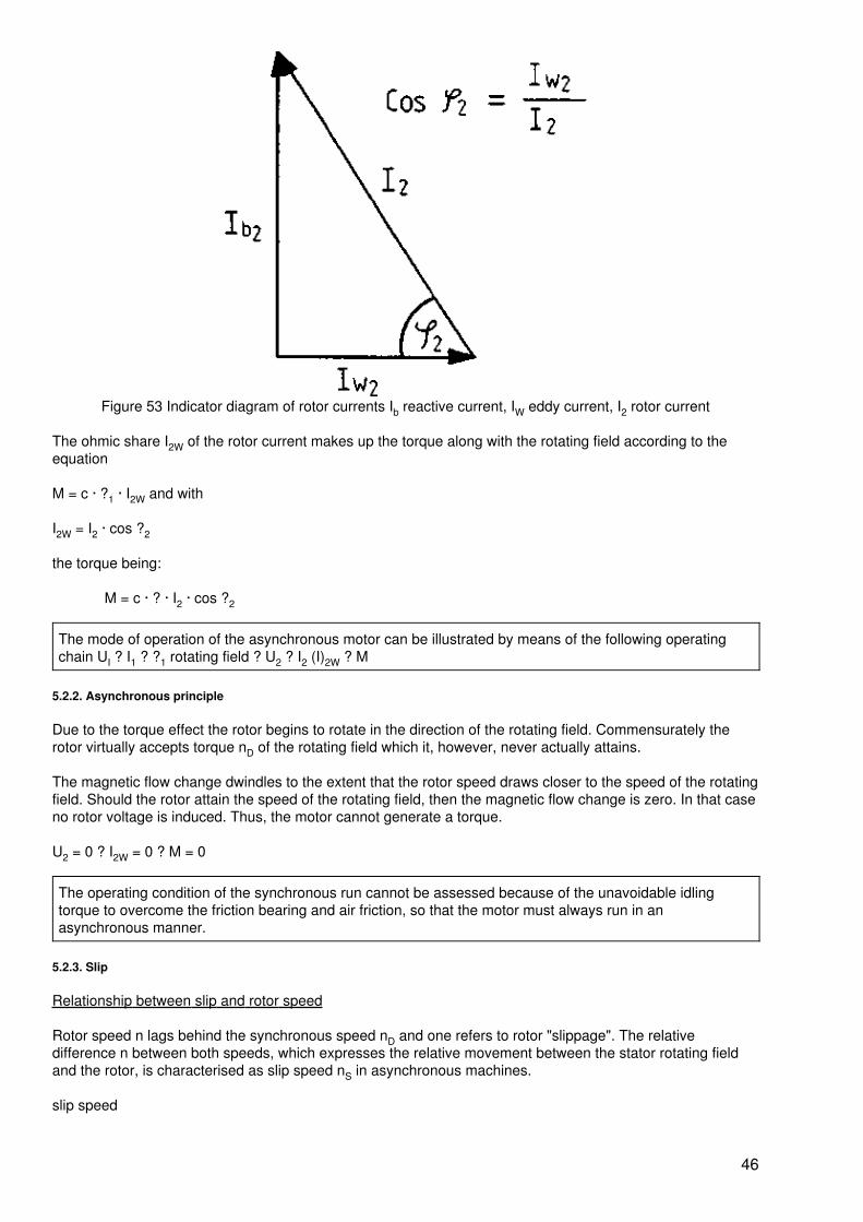
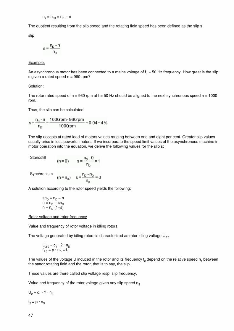
Figure 53 Indicator diagram of rotor currents Ib reactive current, IW eddy current, I2 rotor current
The ohmic share I2W of the rotor current makes up the torque along with the rotating field according to theequation
M = c · ?1 · I2W and with
I2W = I2 · cos ?2
the torque being:
M = c · ? · I2 · cos ?2
The mode of operation of the asynchronous motor can be illustrated by means of the following operatingchain UI ? I1 ? ?1 rotating field ? U2 ? I2 (I)2W ? M
5.2.2. Asynchronous principle
Due to the torque effect the rotor begins to rotate in the direction of the rotating field. Commensurately therotor virtually accepts torque nD of the rotating field which it, however, never actually attains.
The magnetic flow change dwindles to the extent that the rotor speed draws closer to the speed of the rotatingfield. Should the rotor attain the speed of the rotating field, then the magnetic flow change is zero. In that caseno rotor voltage is induced. Thus, the motor cannot generate a torque.
U2 = 0 ? I2W = 0 ? M = 0
The operating condition of the synchronous run cannot be assessed because of the unavoidable idlingtorque to overcome the friction bearing and air friction, so that the motor must always run in anasynchronous manner.
5.2.3. Slip
Relationship between slip and rotor speed
Rotor speed n lags behind the synchronous speed nD and one refers to rotor "slippage". The relativedifference n between both speeds, which expresses the relative movement between the stator rotating fieldand the rotor, is characterised as slip speed nS in asynchronous machines.
slip speed
46
ns = nrel = nD − n
The quotient resulting from the slip speed and the rotating field speed has been defined as the slip s
slip
Example:
An asynchronous motor has been connected to a mains voltage of f1 = 50 Hz frequency. How great is the slips given a rated speed n = 960 rpm?
Solution:
The rotor rated speed of n = 960 rpm at f = 50 Hz should be aligned to the next synchronous speed n = 1000rpm.
Thus, the slip can be calculated
The slip accepts at rated load of motors values ranging between one and eight per cent. Greater slip valuesusually arise in less powerful motors. If we incorporate the speed limit values of the asynchronous machine inmotor operation into the equation, we derive the following values for the slip s:
Standstill
Synchronism
A solution according to the rotor speed yields the following:
snD = nD − nn = nD − snDn = nD (1−s)
Rotor voltage and rotor frequency
Value and frequency of rotor voltage in idling rotors.
The voltage generated by idling rotors is characterized as rotor idling voltage U2.0
U2.0 = c1 · ? · nDf2.0 = p · nD = f1
The values of the voltage U induced in the rotor and its frequency f2 depend on the relative speed ns betweenthe stator rotating field and the rotor, that is to say, the slip.
These values are there called slip voltage resp. slip frequency.
Value and frequency of the rotor voltage given any slip speed nS
U2 = c1 · ? · nS
t2 = p · nS
47
If the establishes the quotient U2/U2.0 resp. f2/f1, one derives
and thus
U2 = s U2.0
resp. with
? = 2 · ? · f?2 = s · ?1
The voltage (U2) induced in the rotor and its frequency f2 are proportional to the slip.
5.3. Operational behaviour
5.3.1. Start
Inrush current origin
As soon as the current is switched on the rotating field rotates at full speed along the rotor bars of the squirrelcage rotor.
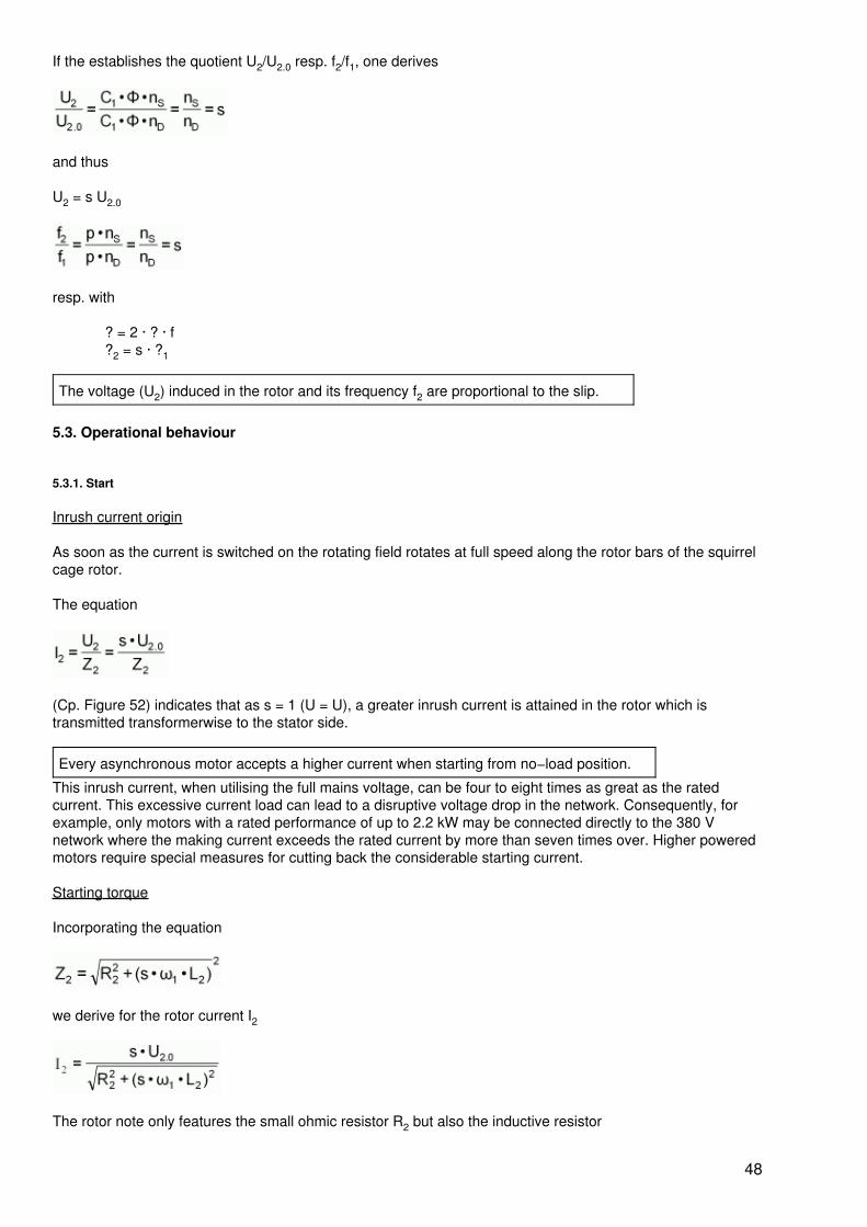
The equation
(Cp. Figure 52) indicates that as s = 1 (U = U), a greater inrush current is attained in the rotor which istransmitted transformerwise to the stator side.
Every asynchronous motor accepts a higher current when starting from no−load position.
This inrush current, when utilising the full mains voltage, can be four to eight times as great as the ratedcurrent. This excessive current load can lead to a disruptive voltage drop in the network. Consequently, forexample, only motors with a rated performance of up to 2.2 kW may be connected directly to the 380 Vnetwork where the making current exceeds the rated current by more than seven times over. Higher poweredmotors require special measures for cutting back the considerable starting current.
Starting torque
Incorporating the equation
we derive for the rotor current I2
The rotor note only features the small ohmic resistor R2 but also the inductive resistor
48
XL2= s · ?1 · L2
= s · 2 · ? · f1 · L2
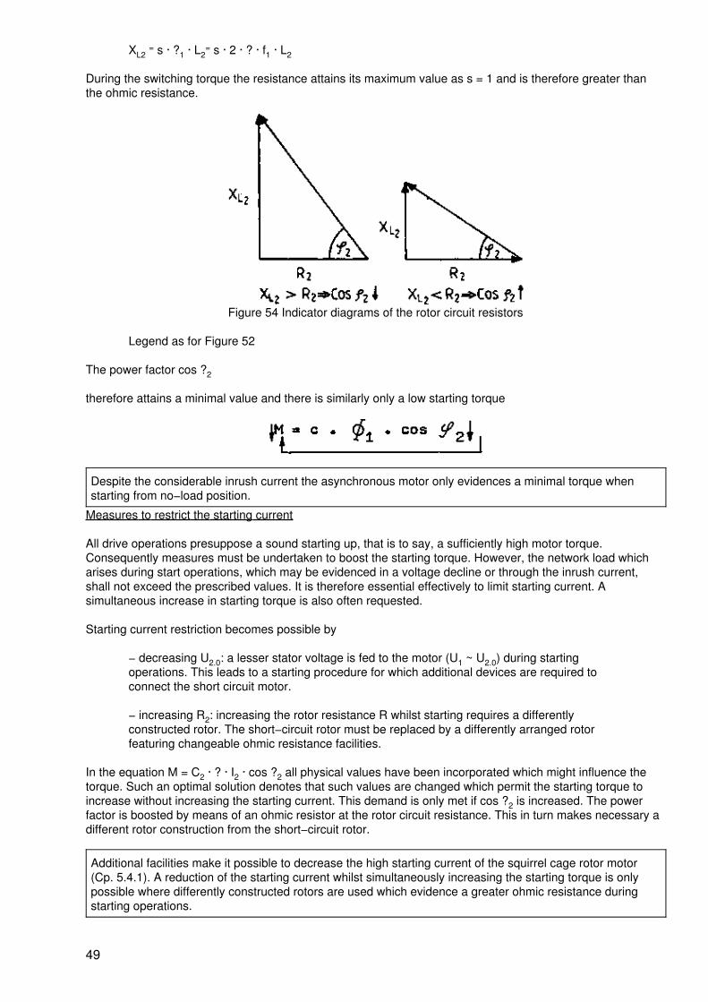
During the switching torque the resistance attains its maximum value as s = 1 and is therefore greater thanthe ohmic resistance.
Figure 54 Indicator diagrams of the rotor circuit resistors
Legend as for Figure 52
The power factor cos ?2
therefore attains a minimal value and there is similarly only a low starting torque
Despite the considerable inrush current the asynchronous motor only evidences a minimal torque whenstarting from no−load position.
Measures to restrict the starting current
All drive operations presuppose a sound starting up, that is to say, a sufficiently high motor torque.Consequently measures must be undertaken to boost the starting torque. However, the network load whicharises during start operations, which may be evidenced in a voltage decline or through the inrush current,shall not exceed the prescribed values. It is therefore essential effectively to limit starting current. Asimultaneous increase in starting torque is also often requested.
Starting current restriction becomes possible by
− decreasing U2.0: a lesser stator voltage is fed to the motor (U1 ~ U2.0) during startingoperations. This leads to a starting procedure for which additional devices are required toconnect the short circuit motor.
− increasing R2: increasing the rotor resistance R whilst starting requires a differentlyconstructed rotor. The short−circuit rotor must be replaced by a differently arranged rotorfeaturing changeable ohmic resistance facilities.
In the equation M = C2 · ? · I2 · cos ?2 all physical values have been incorporated which might influence thetorque. Such an optimal solution denotes that such values are changed which permit the starting torque toincrease without increasing the starting current. This demand is only met if cos ?2 is increased. The powerfactor is boosted by means of an ohmic resistor at the rotor circuit resistance. This in turn makes necessary adifferent rotor construction from the short−circuit rotor.
Additional facilities make it possible to decrease the high starting current of the squirrel cage rotor motor(Cp. 5.4.1). A reduction of the starting current whilst simultaneously increasing the starting torque is onlypossible where differently constructed rotors are used which evidence a greater ohmic resistance duringstarting operations.
49
5.3.2. Rating
Speed behaviour depending on the torque
Operating an asynchronous motor presupposes a certain speed for a given torque. This ratio is given for anyone motor.
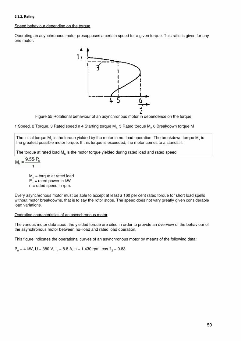
Figure 55 Rotational behaviour of an asynchronous motor in dependence on the torque
1 Speed, 2 Torque, 3 Rated speed n 4 Starting torque Ma, 5 Rated torque Mn 6 Breakdown torque M
The initial torque Ma is the torque yielded by the motor in no−load operation. The breakdown torque Mk isthe greatest possible motor torque. If this torque is exceeded, the motor comes to a standstill.
The torque at rated load Mn is the motor torque yielded during rated load and rated speed.
Mn = torque at rated loadPn = rated power in kWn = rated speed in rpm.
Every asynchronous motor must be able to accept at least a 160 per cent rated torque for short load spellswithout motor breakdowns, that is to say the rotor stops. The speed does not vary greatly given considerableload variations.
Operating characteristics of an asynchronous motor
The various motor data about the yielded torque are cited in order to provide an overview of the behaviour ofthe asynchronous motor between no−load and rated load operation.
This figure indicates the operational curves of an asynchronous motor by means of the following data:
Pn = 4 kW, U = 380 V, In = 8.8 A, n = 1.430 rpm. cos ?2 = 0.83
50
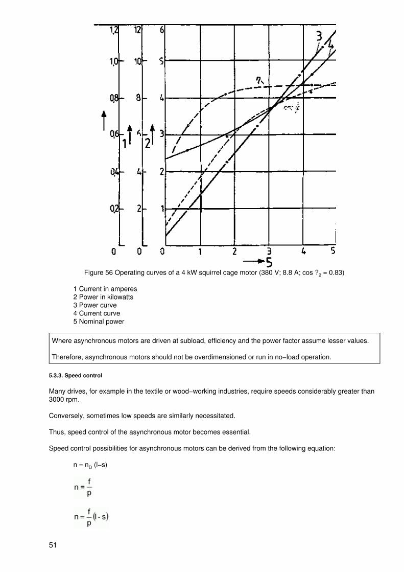
Figure 56 Operating curves of a 4 kW squirrel cage motor (380 V; 8.8 A; cos ?2 = 0.83)
1 Current in amperes2 Power in kilowatts3 Power curve4 Current curve5 Nominal power
Where asynchronous motors are driven at subload, efficiency and the power factor assume lesser values.
Therefore, asynchronous motors should not be overdimensioned or run in no−load operation.
5.3.3. Speed control
Many drives, for example in the textile or wood−working industries, require speeds considerably greater than3000 rpm.
Conversely, sometimes low speeds are similarly necessitated.
Thus, speed control of the asynchronous motor becomes essential.
Speed control possibilities for asynchronous motors can be derived from the following equation:
n = nD (l−s)
51
The speed established given a certain torque can therefore be influenced by:
− frequency change in the supplied there−phase alternating current through the employmentof rotating frequency converters of through alternating or converter circuits with adjustablefrequencies.
− altering the number of pole pairs through pole changing. This can ensue in two ways. Eitherby means of two or several separate stator windings which can be switched on as desired orby switching over parts of a single stator winding (Dahlander pole−changing circuit).
− altering the slip by changing the voltage application UI by means of series resistors oradjustable transformers, resp. by changing the ohmic resistance R2 in the rotor circuit (slipring rotor).
The most commonly employed adjustment procedures are those of circuit engineering as cited in section5.4.2.
5.3.4. Rotational sense alteration
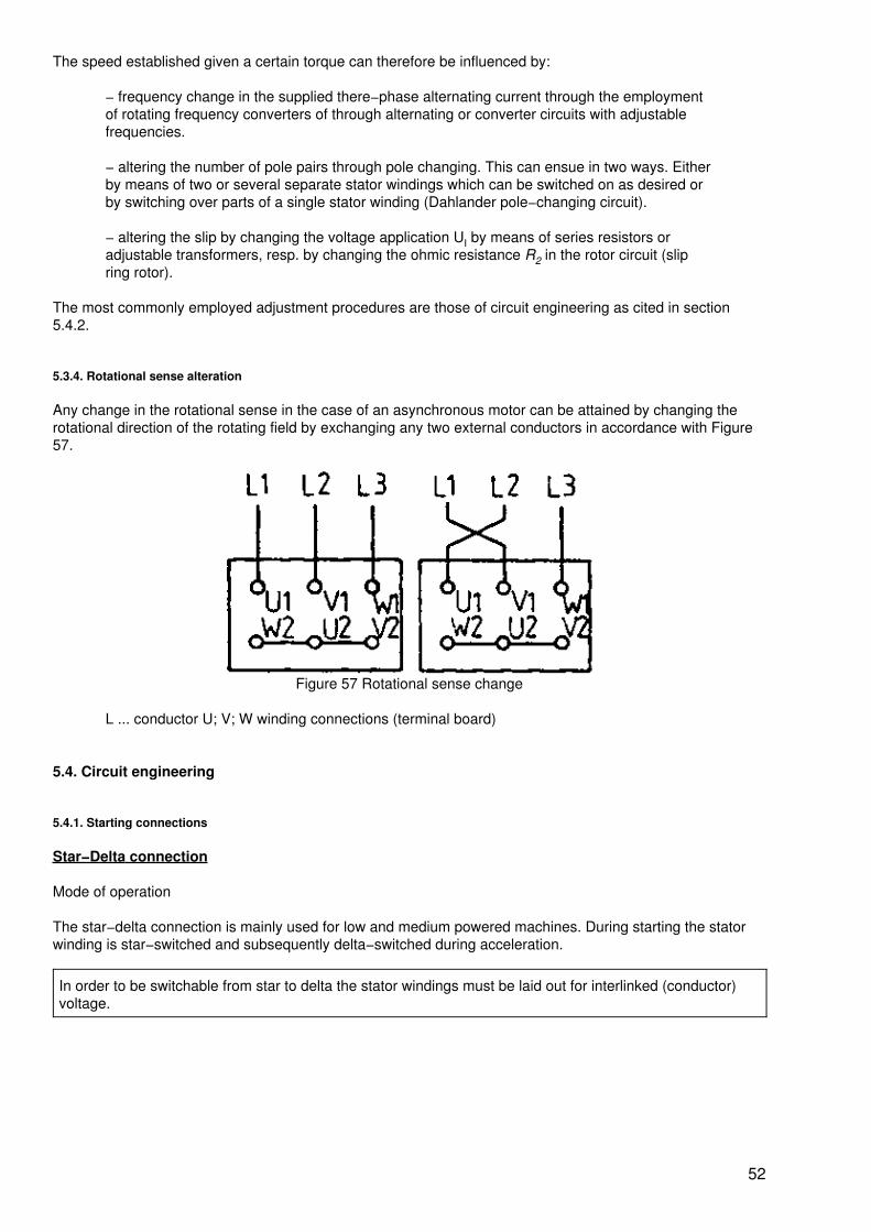
Any change in the rotational sense in the case of an asynchronous motor can be attained by changing therotational direction of the rotating field by exchanging any two external conductors in accordance with Figure57.
Figure 57 Rotational sense change
L ... conductor U; V; W winding connections (terminal board)
5.4. Circuit engineering
5.4.1. Starting connections
Star−Delta connection
Mode of operation
The star−delta connection is mainly used for low and medium powered machines. During starting the statorwinding is star−switched and subsequently delta−switched during acceleration.
In order to be switchable from star to delta the stator windings must be laid out for interlinked (conductor)voltage.
52
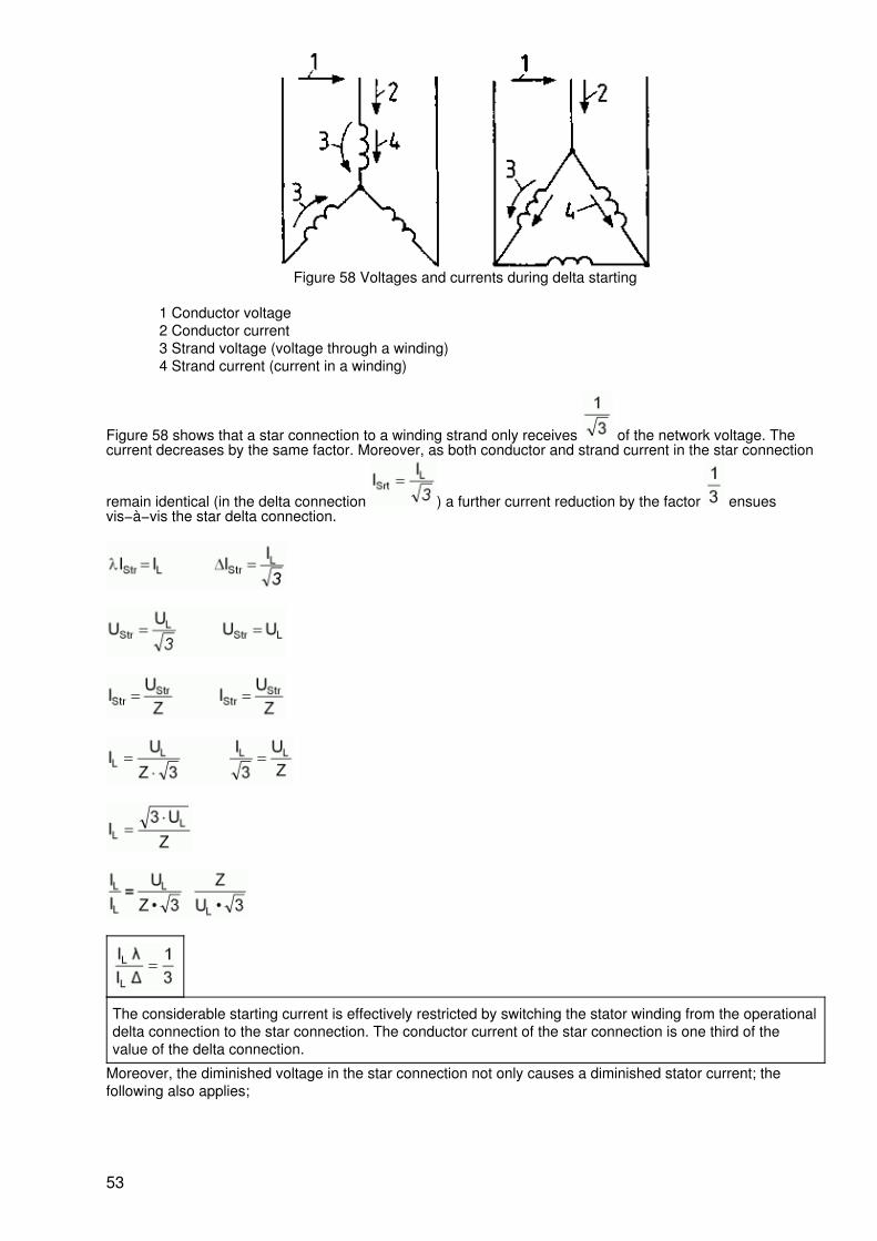
Figure 58 Voltages and currents during delta starting
1 Conductor voltage2 Conductor current3 Strand voltage (voltage through a winding)4 Strand current (current in a winding)
Figure 58 shows that a star connection to a winding strand only receives of the network voltage. Thecurrent decreases by the same factor. Moreover, as both conductor and strand current in the star connection
remain identical (in the delta connection ) a further current reduction by the factor ensuesvis−à−vis the star delta connection.
The considerable starting current is effectively restricted by switching the stator winding from the operationaldelta connection to the star connection. The conductor current of the star connection is one third of thevalue of the delta connection.
Moreover, the diminished voltage in the star connection not only causes a diminished stator current; thefollowing also applies;
53
The initial torque in the star connection is but one third of its value in the delta connection.
The advantage of the star−delta connection for limiting the considerable starting current in an effectivemanner is, however, only possible through a further reduction in the already minimal initial torque. In manycases it will be necessary when employing this starting procedure to start up the motor without load.
Circuitry
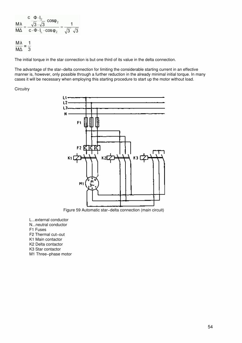
Figure 59 Automatic star−delta connection (main circuit)
L...external conductorN...neutral conductorF1 FusesF2 Thermal cut−outK1 Main contactorK2 Delta contactorK3 Star contactorM1 Three−phase motor
54
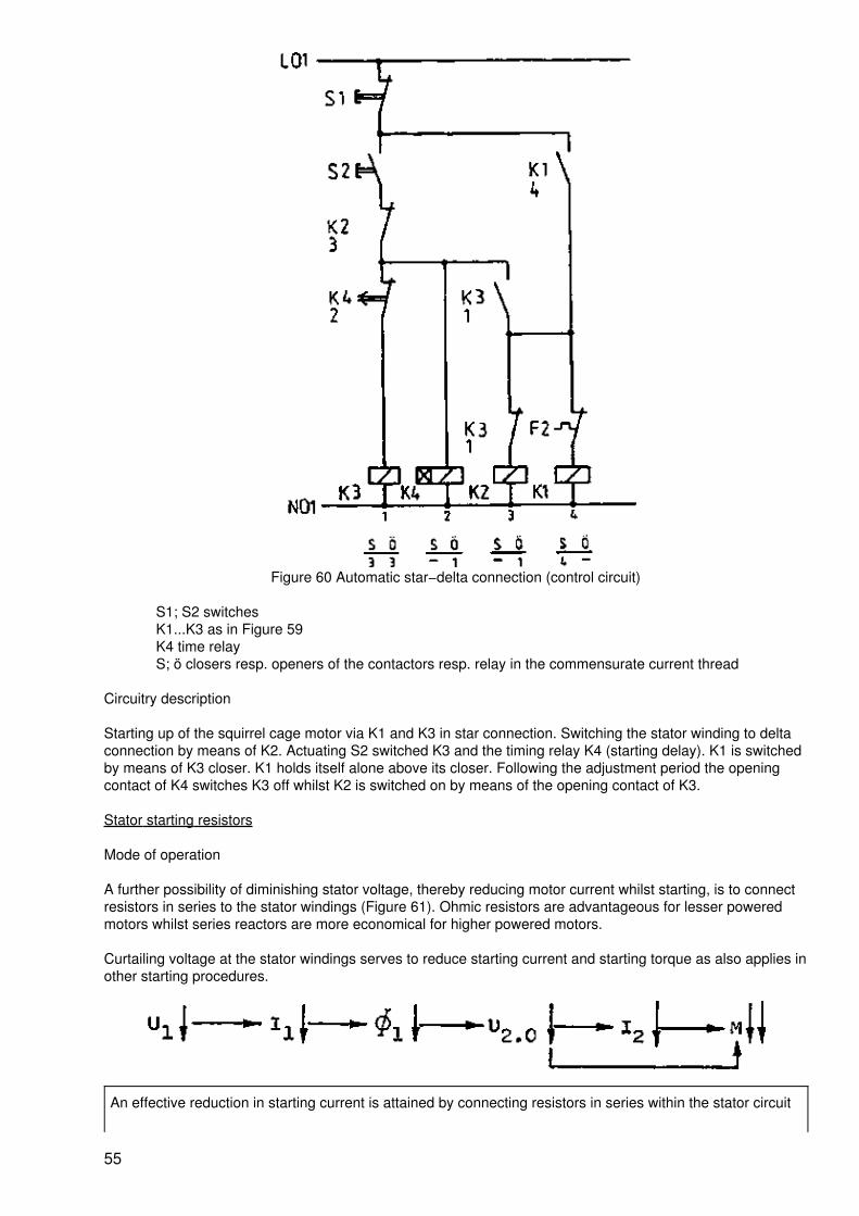
Figure 60 Automatic star−delta connection (control circuit)
S1; S2 switchesK1...K3 as in Figure 59K4 time relayS; ö closers resp. openers of the contactors resp. relay in the commensurate current thread
Circuitry description
Starting up of the squirrel cage motor via K1 and K3 in star connection. Switching the stator winding to deltaconnection by means of K2. Actuating S2 switched K3 and the timing relay K4 (starting delay). K1 is switchedby means of K3 closer. K1 holds itself alone above its closer. Following the adjustment period the openingcontact of K4 switches K3 off whilst K2 is switched on by means of the opening contact of K3.
Stator starting resistors
Mode of operation
A further possibility of diminishing stator voltage, thereby reducing motor current whilst starting, is to connectresistors in series to the stator windings (Figure 61). Ohmic resistors are advantageous for lesser poweredmotors whilst series reactors are more economical for higher powered motors.
Curtailing voltage at the stator windings serves to reduce starting current and starting torque as also applies inother starting procedures.
An effective reduction in starting current is attained by connecting resistors in series within the stator circuit
55
in conjunction with a pronounced decline in starting torque.
This procedure is however only suitable for no−load running motors. In order to ensure a smoother and slowerstarting (i.e. to exclude torque impulses from impact−switched gears) it is sufficient whilst starting to connectan ohmic resistance or a coil in a lead (Kusa circuit). The significance of this resistance is illustrated in thefollowing for both limit values.
RV ? ? The limit current motor is fed from one side only from the stator. Consequently there is norotating field and the motor does not develop a torque.
RV = 0 The asynchronous motor is connected directly. The motor develops the maximum possibletorque.
With the help of the resistor RV in a lead it becomes possible to adjust the possible starting torques betweenzero and the possible maximum value. Impact−free starting becomes possible. As a result of the circuitasymmetry the conduction currents are distributed unequally in the three leads. An effective reduction ofstarting current is not possible. Current only declines in the strand with the series connected resistor.
Circuitry
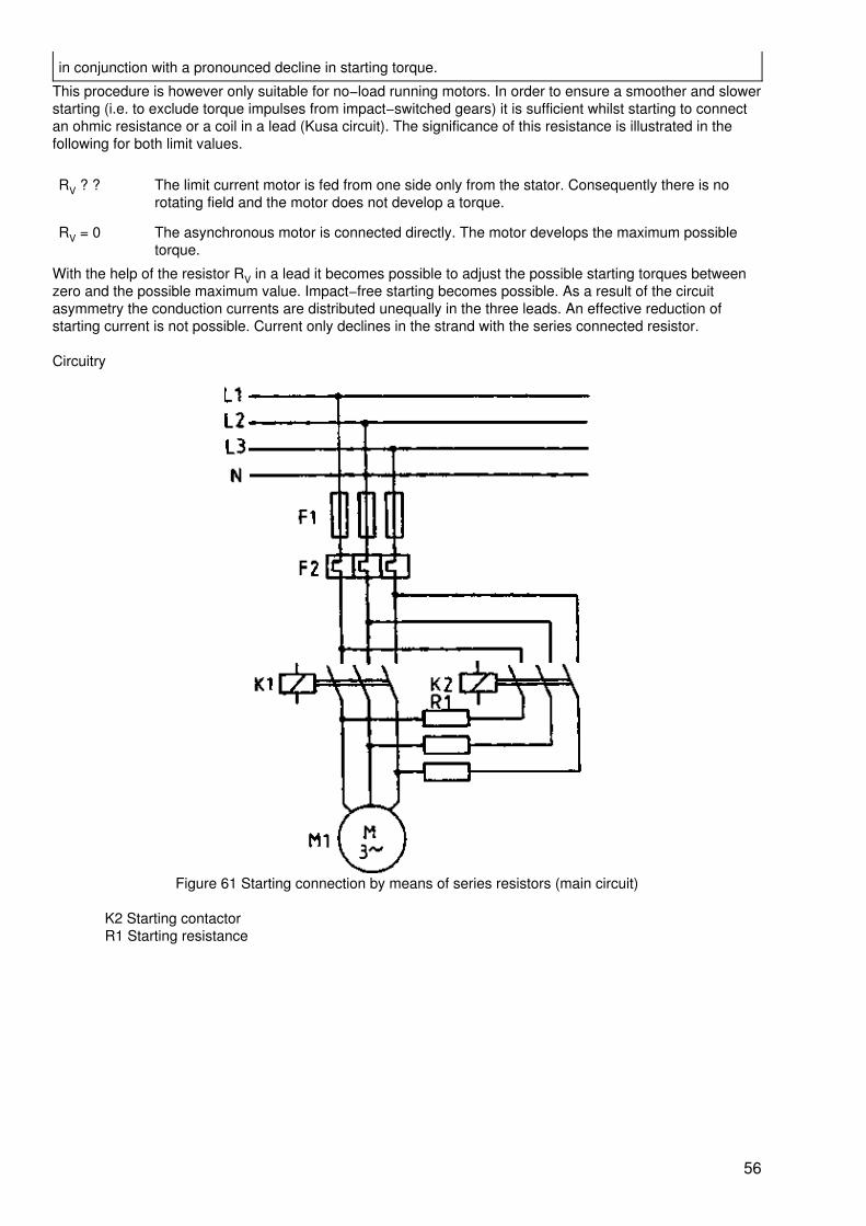
Figure 61 Starting connection by means of series resistors (main circuit)
K2 Starting contactorR1 Starting resistance
56
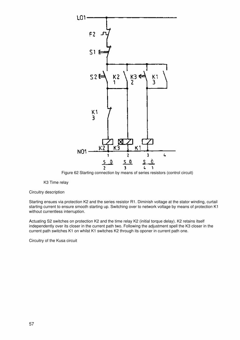
Figure 62 Starting connection by means of series resistors (control circuit)
K3 Time relay
Circuitry description
Starting ensues via protection K2 and the series resistor R1. Diminish voltage at the stator winding, curtailstarting current to ensure smooth starting up. Switching over to network voltage by means of protection K1without currentless interruption.
Actuating S2 switches on protection K2 and the time relay K2 (initial torque delay). K2 retains itselfindependently over its closer in the current path two. Following the adjustment spell the K3 closer in thecurrent path switches K1 on whilst K1 switches K2 through its oponer in current path one.
Circuitry of the Kusa circuit
57
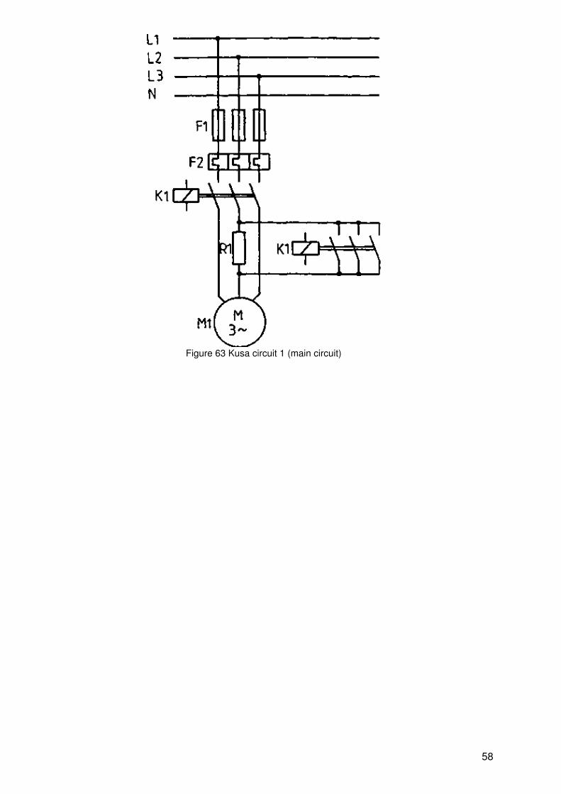
Figure 63 Kusa circuit 1 (main circuit)
58

Figure 64 Kusa circuit 1 (control circuit)
59
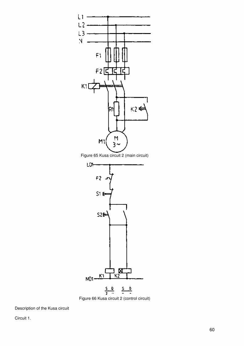
Figure 65 Kusa circuit 2 (main circuit)
Figure 66 Kusa circuit 2 (control circuit)
Description of the Kusa circuit
Circuit 1.
60
By actuating S2 K1 and the time relay K3 are switched on (initial torque delay). K1 is retained independentlyabove its closer in current path 2. Following the adjustment spell the closer of K3 in current path 3 switches onK2 which maintains itself above its closer in current path 4 and switches K3 off by means of its opener incurrent path 2.
Circuit 2.
By actuating S2 K1 and the time relay K2 (initial torque delay) are switched on. Following the adjustment spellR1 is short−circuited by the closer of the time relay (in Figure 65).
Slip ring motor
Mode of operation
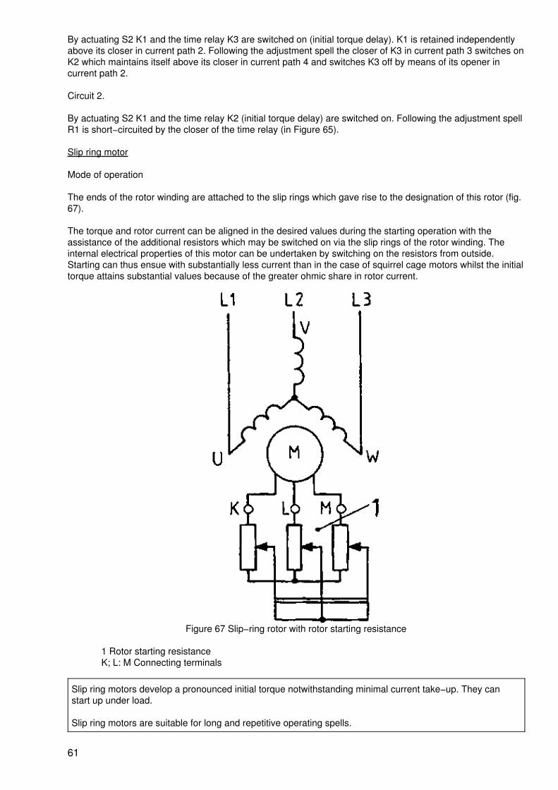
The ends of the rotor winding are attached to the slip rings which gave rise to the designation of this rotor (fig.67).
The torque and rotor current can be aligned in the desired values during the starting operation with theassistance of the additional resistors which may be switched on via the slip rings of the rotor winding. Theinternal electrical properties of this motor can be undertaken by switching on the resistors from outside.Starting can thus ensue with substantially less current than in the case of squirrel cage motors whilst the initialtorque attains substantial values because of the greater ohmic share in rotor current.
Figure 67 Slip−ring rotor with rotor starting resistance
1 Rotor starting resistanceK; L: M Connecting terminals
Slip ring motors develop a pronounced initial torque notwithstanding minimal current take−up. They canstart up under load.
Slip ring motors are suitable for long and repetitive operating spells.
61
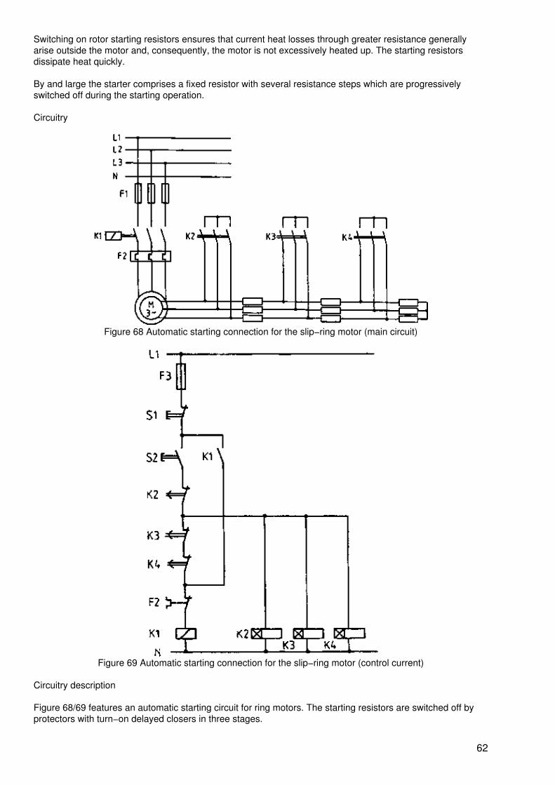
Switching on rotor starting resistors ensures that current heat losses through greater resistance generallyarise outside the motor and, consequently, the motor is not excessively heated up. The starting resistorsdissipate heat quickly.
By and large the starter comprises a fixed resistor with several resistance steps which are progressivelyswitched off during the starting operation.
Circuitry
Figure 68 Automatic starting connection for the slip−ring motor (main circuit)
Figure 69 Automatic starting connection for the slip−ring motor (control current)
Circuitry description
Figure 68/69 features an automatic starting circuit for ring motors. The starting resistors are switched off byprotectors with turn−on delayed closers in three stages.
62
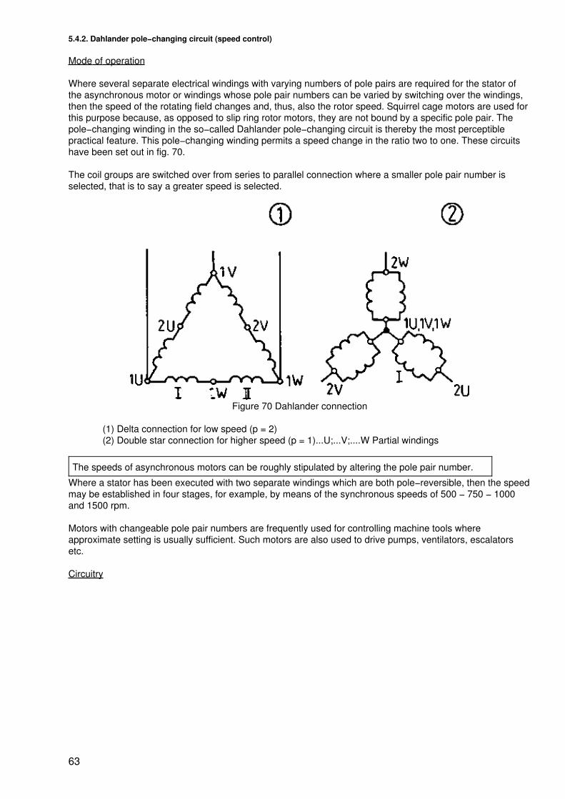
5.4.2. Dahlander pole−changing circuit (speed control)
Mode of operation
Where several separate electrical windings with varying numbers of pole pairs are required for the stator ofthe asynchronous motor or windings whose pole pair numbers can be varied by switching over the windings,then the speed of the rotating field changes and, thus, also the rotor speed. Squirrel cage motors are used forthis purpose because, as opposed to slip ring rotor motors, they are not bound by a specific pole pair. Thepole−changing winding in the so−called Dahlander pole−changing circuit is thereby the most perceptiblepractical feature. This pole−changing winding permits a speed change in the ratio two to one. These circuitshave been set out in fig. 70.
The coil groups are switched over from series to parallel connection where a smaller pole pair number isselected, that is to say a greater speed is selected.
Figure 70 Dahlander connection
(1) Delta connection for low speed (p = 2)(2) Double star connection for higher speed (p = 1)...U;...V;....W Partial windings
The speeds of asynchronous motors can be roughly stipulated by altering the pole pair number.
Where a stator has been executed with two separate windings which are both pole−reversible, then the speedmay be established in four stages, for example, by means of the synchronous speeds of 500 − 750 − 1000and 1500 rpm.
Motors with changeable pole pair numbers are frequently used for controlling machine tools whereapproximate setting is usually sufficient. Such motors are also used to drive pumps, ventilators, escalatorsetc.
Circuitry
63
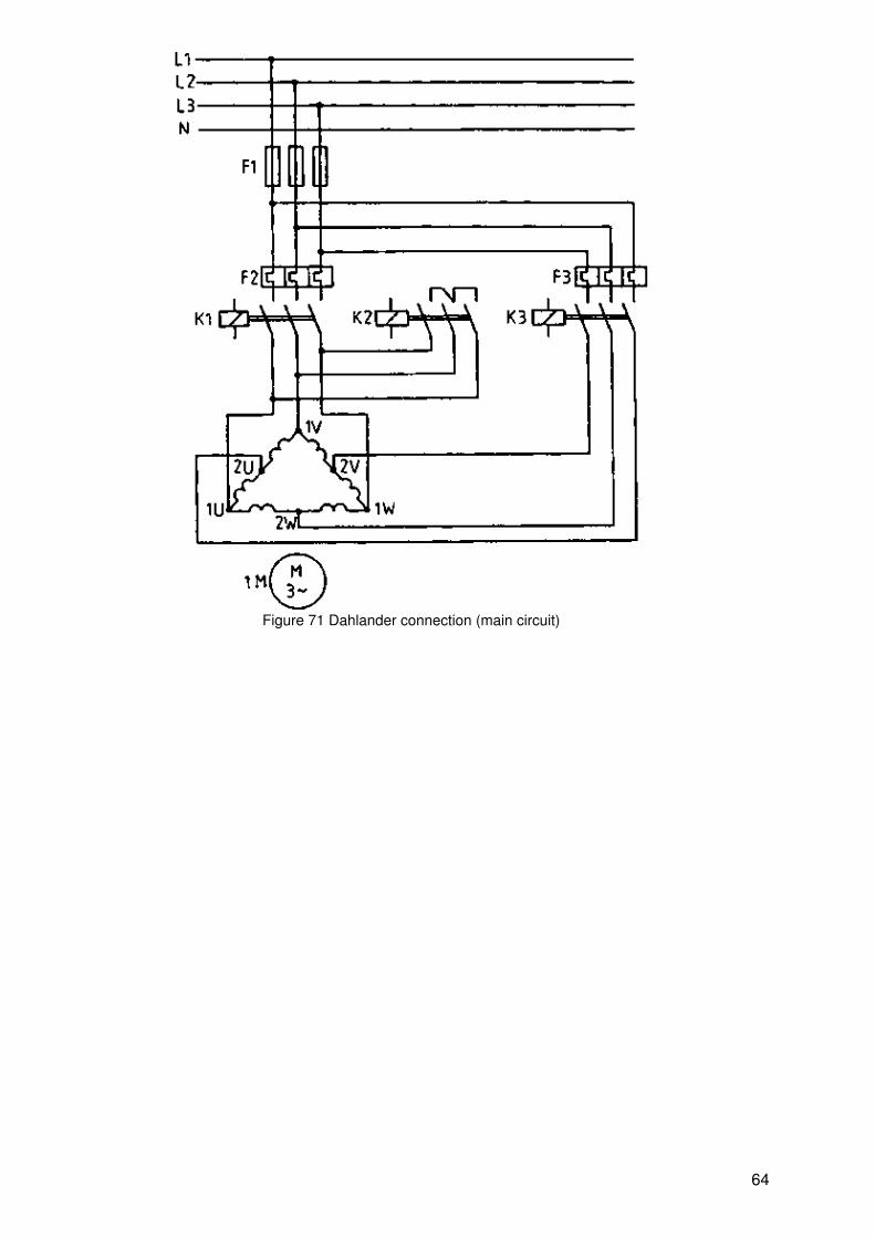
Figure 71 Dahlander connection (main circuit)
64
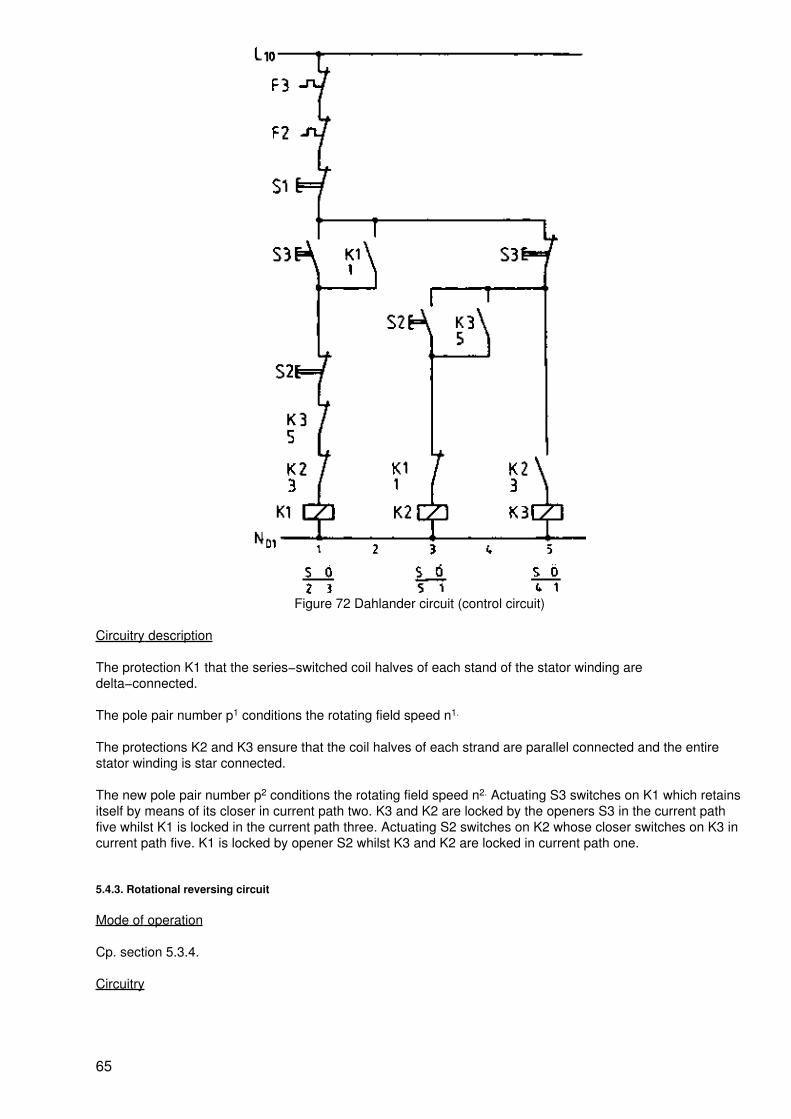
Figure 72 Dahlander circuit (control circuit)
Circuitry description
The protection K1 that the series−switched coil halves of each stand of the stator winding aredelta−connected.
The pole pair number p1 conditions the rotating field speed n1.
The protections K2 and K3 ensure that the coil halves of each strand are parallel connected and the entirestator winding is star connected.
The new pole pair number p2 conditions the rotating field speed n2. Actuating S3 switches on K1 which retainsitself by means of its closer in current path two. K3 and K2 are locked by the openers S3 in the current pathfive whilst K1 is locked in the current path three. Actuating S2 switches on K2 whose closer switches on K3 incurrent path five. K1 is locked by opener S2 whilst K3 and K2 are locked in current path one.
5.4.3. Rotational reversing circuit
Mode of operation
Cp. section 5.3.4.
Circuitry
65
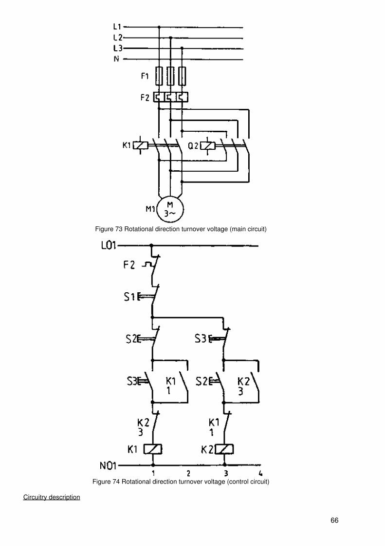
Figure 73 Rotational direction turnover voltage (main circuit)
Figure 74 Rotational direction turnover voltage (control circuit)
Circuitry description
66
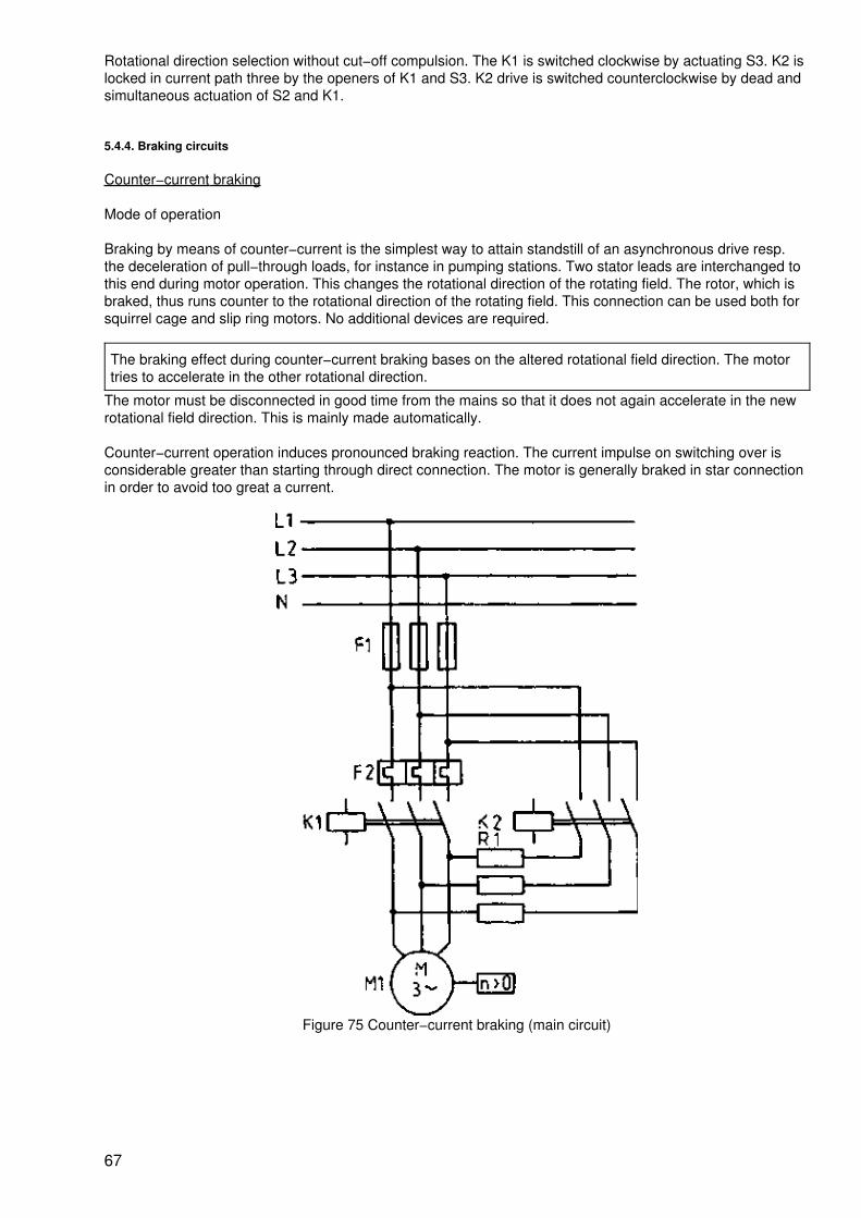
Rotational direction selection without cut−off compulsion. The K1 is switched clockwise by actuating S3. K2 islocked in current path three by the openers of K1 and S3. K2 drive is switched counterclockwise by dead andsimultaneous actuation of S2 and K1.
5.4.4. Braking circuits
Counter−current braking
Mode of operation
Braking by means of counter−current is the simplest way to attain standstill of an asynchronous drive resp.the deceleration of pull−through loads, for instance in pumping stations. Two stator leads are interchanged tothis end during motor operation. This changes the rotational direction of the rotating field. The rotor, which isbraked, thus runs counter to the rotational direction of the rotating field. This connection can be used both forsquirrel cage and slip ring motors. No additional devices are required.
The braking effect during counter−current braking bases on the altered rotational field direction. The motortries to accelerate in the other rotational direction.
The motor must be disconnected in good time from the mains so that it does not again accelerate in the newrotational field direction. This is mainly made automatically.
Counter−current operation induces pronounced braking reaction. The current impulse on switching over isconsiderable greater than starting through direct connection. The motor is generally braked in star connectionin order to avoid too great a current.
Figure 75 Counter−current braking (main circuit)
67
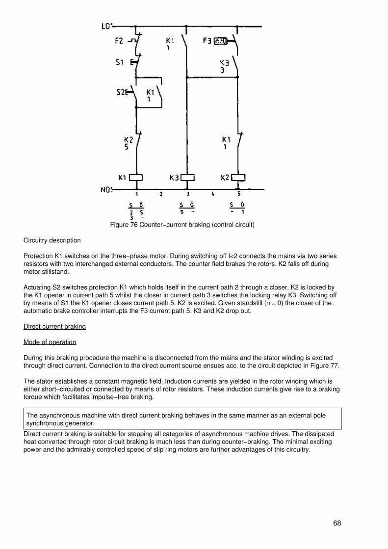
Figure 76 Counter−current braking (control circuit)
Circuitry description
Protection K1 switches on the three−phase motor. During switching off l<2 connects the mains via two seriesresistors with two interchanged external conductors. The counter field brakes the rotors. K2 falls off duringmotor stillstand.
Actuating S2 switches protection K1 which holds itself in the current path 2 through a closer. K2 is locked bythe K1 opener in current path 5 whilst the closer in current path 3 switches the locking relay K3. Switching offby means of S1 the K1 opener closes current path 5. K2 is excited. Given standstill (n = 0) the closer of theautomatic brake controller interrupts the F3 current path 5. K3 and K2 drop out.
Direct current braking
Mode of operation
During this braking procedure the machine is disconnected from the mains and the stator winding is excitedthrough direct current. Connection to the direct current source ensues acc. to the circuit depicted in Figure 77.
The stator establishes a constant magnetic field. Induction currents are yielded in the rotor winding which iseither short−circuited or connected by means of rotor resistors. These induction currents give rise to a brakingtorque which facilitates impulse−free braking.
The asynchronous machine with direct current braking behaves in the same manner as an external polesynchronous generator.
Direct current braking is suitable for stopping all categories of asynchronous machine drives. The dissipatedheat converted through rotor circuit braking is much less than during counter−braking. The minimal excitingpower and the admirably controlled speed of slip ring motors are further advantages of this circuitry.
68
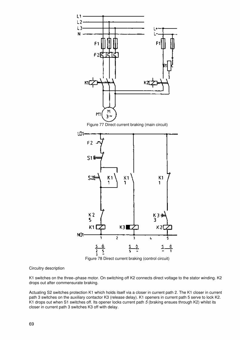
Figure 77 Direct current braking (main circuit)
Figure 78 Direct current braking (control circuit)
Circuitry description
K1 switches on the three−phase motor. On switching off K2 connects direct voltage to the stator winding. K2drops out after commensurate braking.
Actuating S2 switches protection K1 which holds itself via a closer in current path 2. The K1 closer in currentpath 3 switches on the auxiliary contactor K3 (release delay). K1 openers in current path 5 serve to lock K2.K1 drops out when S1 switches off. Its opener locks current path 5 (braking ensues through K2) whilst itscloser in current path 3 switches K3 off with delay.
69
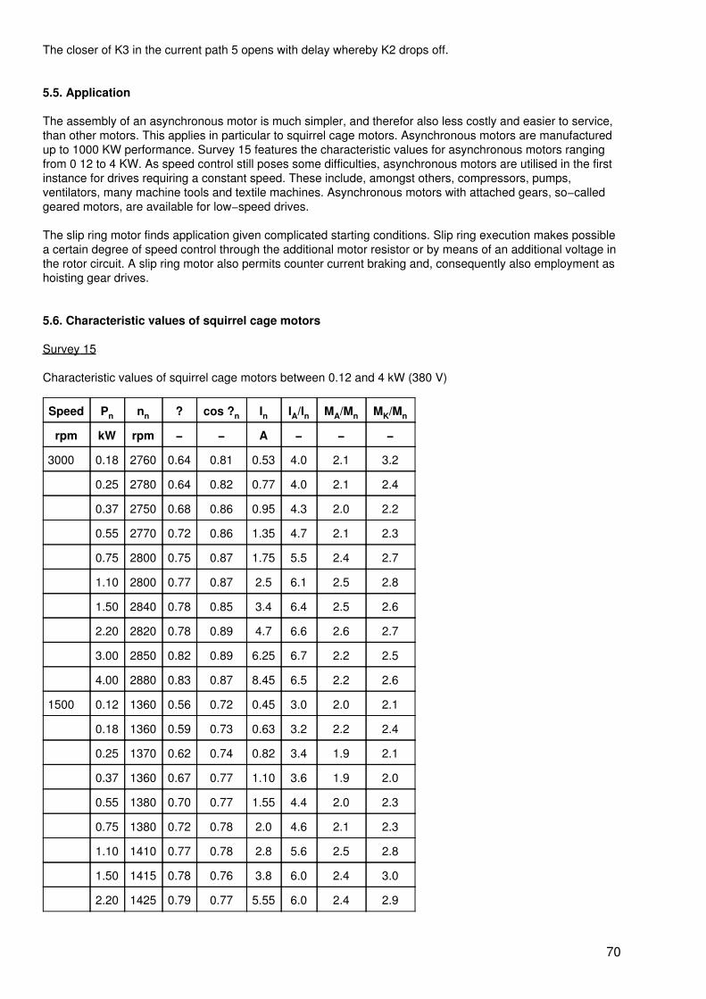
The closer of K3 in the current path 5 opens with delay whereby K2 drops off.
5.5. Application
The assembly of an asynchronous motor is much simpler, and therefor also less costly and easier to service,than other motors. This applies in particular to squirrel cage motors. Asynchronous motors are manufacturedup to 1000 KW performance. Survey 15 features the characteristic values for asynchronous motors rangingfrom 0 12 to 4 KW. As speed control still poses some difficulties, asynchronous motors are utilised in the firstinstance for drives requiring a constant speed. These include, amongst others, compressors, pumps,ventilators, many machine tools and textile machines. Asynchronous motors with attached gears, so−calledgeared motors, are available for low−speed drives.
The slip ring motor finds application given complicated starting conditions. Slip ring execution makes possiblea certain degree of speed control through the additional motor resistor or by means of an additional voltage inthe rotor circuit. A slip ring motor also permits counter current braking and, consequently also employment ashoisting gear drives.
5.6. Characteristic values of squirrel cage motors
Survey 15
Characteristic values of squirrel cage motors between 0.12 and 4 kW (380 V)
Speed Pn nn ? cos ?n In IA/In MA/Mn MK/Mn
rpm kW rpm − − A − − −
3000 0.18 2760 0.64 0.81 0.53 4.0 2.1 3.2
0.25 2780 0.64 0.82 0.77 4.0 2.1 2.4
0.37 2750 0.68 0.86 0.95 4.3 2.0 2.2
0.55 2770 0.72 0.86 1.35 4.7 2.1 2.3
0.75 2800 0.75 0.87 1.75 5.5 2.4 2.7
1.10 2800 0.77 0.87 2.5 6.1 2.5 2.8
1.50 2840 0.78 0.85 3.4 6.4 2.5 2.6
2.20 2820 0.78 0.89 4.7 6.6 2.6 2.7
3.00 2850 0.82 0.89 6.25 6.7 2.2 2.5
4.00 2880 0.83 0.87 8.45 6.5 2.2 2.6
1500 0.12 1360 0.56 0.72 0.45 3.0 2.0 2.1
0.18 1360 0.59 0.73 0.63 3.2 2.2 2.4
0.25 1370 0.62 0.74 0.82 3.4 1.9 2.1
0.37 1360 0.67 0.77 1.10 3.6 1.9 2.0
0.55 1380 0.70 0.77 1.55 4.4 2.0 2.3
0.75 1380 0.72 0.78 2.0 4.6 2.1 2.3
1.10 1410 0.77 0.78 2.8 5.6 2.5 2.8
1.50 1415 0.78 0.76 3.8 6.0 2.4 3.0
2.20 1425 0.79 0.77 5.55 6.0 2.4 2.9
70
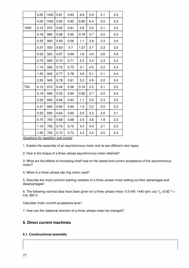
3.00 1430 0.81 0.83 6.8 5.8 2.1 2.5
4.00 1430 0.83 0.83 8.85 6.4 2.5 2.9
1000 0.12 870 0.50 0.61 0.6 2.5 2.1 2.2
0.18 900 0.56 0.62 0.79 2.7 2.0 2.0
0.25 900 0.59 0.58 1.1 2.9 2.3 2.4
0.37 920 0.63 0.7 1.27 3.7 2.3 2.5
0.55 920 0.67 0.69 1.8 4.0 2.6 2.8
0.75 930 0.70 0.71 2.3 4.4 2.3 2.4
1.10 930 0.73 0.73 3.1 4.5 2.2 2,4
1.50 945 0.77 0.78 3.8 5.1 2.1 2.4
2.20 945 0.78 0.81 5.3 4.9 2.0 2.4
750 0.12 670 0.44 0.56 0.74 2.2 2.1 2.2
0.18 690 0.52 0.64 0.82 2.7 2.0 2.4
0.25 690 0.56 0.63 1.1 3.0 2.3 2.5
0.37 690 0.60 0.64 1.5 3.2 2.0 2.2
0.55 690 0.64 0.65 2.0 3.3 2.0 2.1
0.75 700 0.68 0.68 2.5 3.8 1.9 2.3
1.10 700 0.70 0.70 3.4 4.0 2.1 2.5
1.50 700 0.73 0.73 4.3 4.2 2.0 2.4
Questions for repetition and control
1. Explain the assembly of an asynchronous motor and its two different rotor types.
2. How is the torque of a three−phase asynchronous motor attained?
3. What are the effects of increasing shaft load on the speed and current acceptance of the asynchronousmotor?
4. When is a three−phase slip ring motor used?
5. Describe the most common starting varieties of a three−phase motor setting out their advantages anddisadvantages!
6. The following nominal data have been given for a three−phase motor: 5.5 kW; 1440 rpm; cos ?2 =0.82 ? =0.8; 380 V.
Calculate motor current acceptance level !
7. How can the rotational direction of a three−phase motor be changed?
6. Direct current machines
6.1. Constructional assembly
71
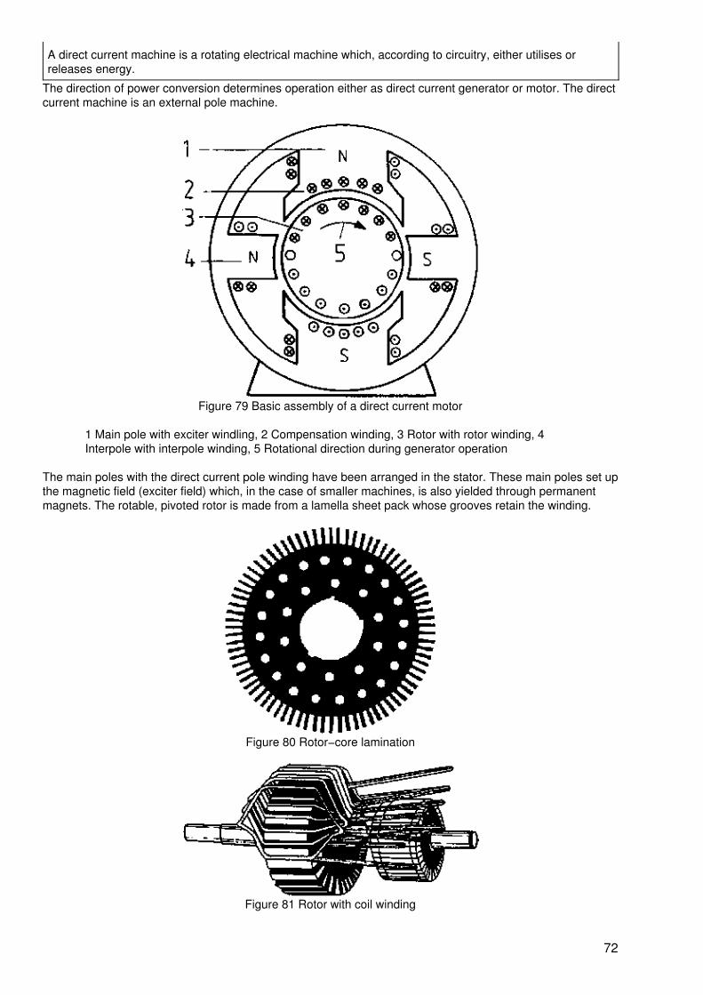
A direct current machine is a rotating electrical machine which, according to circuitry, either utilises orreleases energy.
The direction of power conversion determines operation either as direct current generator or motor. The directcurrent machine is an external pole machine.
Figure 79 Basic assembly of a direct current motor
1 Main pole with exciter windling, 2 Compensation winding, 3 Rotor with rotor winding, 4Interpole with interpole winding, 5 Rotational direction during generator operation
The main poles with the direct current pole winding have been arranged in the stator. These main poles set upthe magnetic field (exciter field) which, in the case of smaller machines, is also yielded through permanentmagnets. The rotable, pivoted rotor is made from a lamella sheet pack whose grooves retain the winding.
Figure 80 Rotor−core lamination
Figure 81 Rotor with coil winding
72
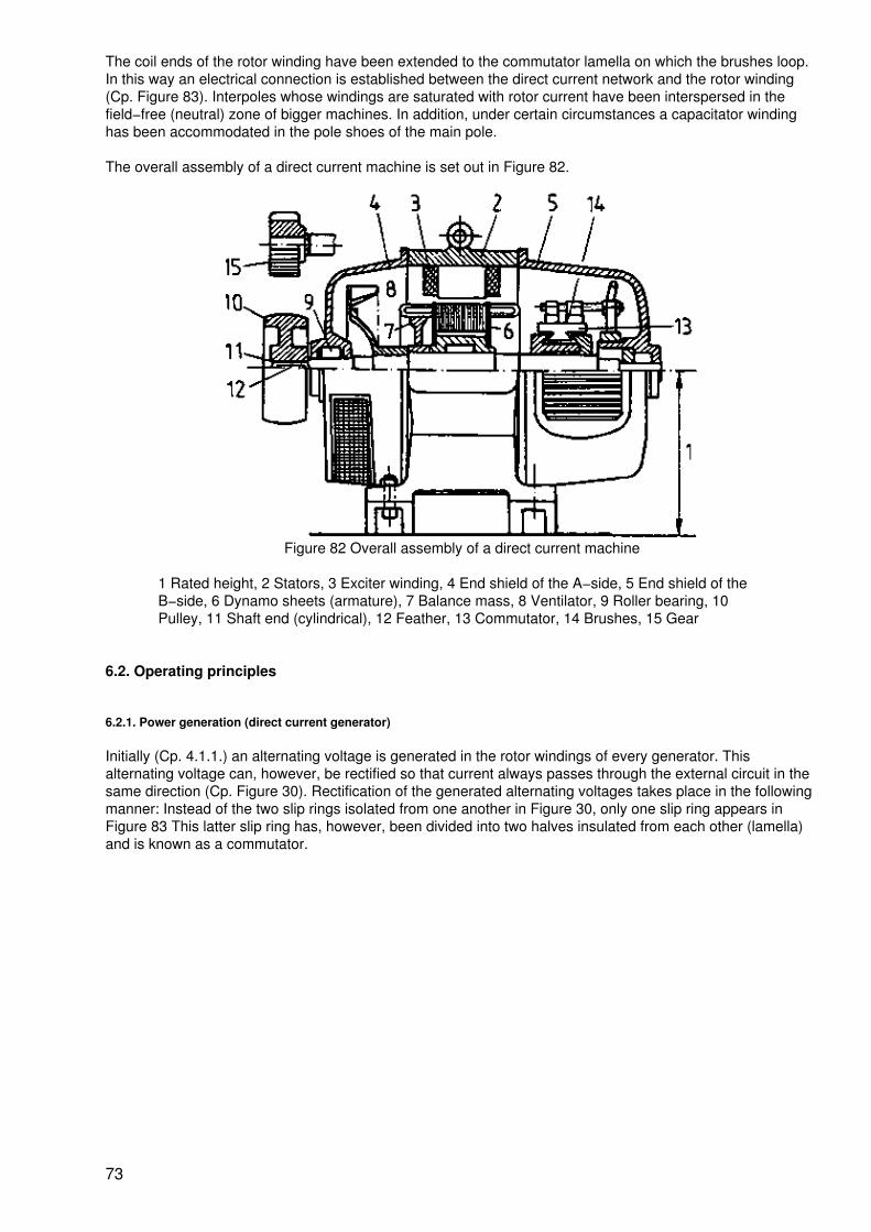
The coil ends of the rotor winding have been extended to the commutator lamella on which the brushes loop.In this way an electrical connection is established between the direct current network and the rotor winding(Cp. Figure 83). Interpoles whose windings are saturated with rotor current have been interspersed in thefield−free (neutral) zone of bigger machines. In addition, under certain circumstances a capacitator windinghas been accommodated in the pole shoes of the main pole.
The overall assembly of a direct current machine is set out in Figure 82.
Figure 82 Overall assembly of a direct current machine
1 Rated height, 2 Stators, 3 Exciter winding, 4 End shield of the A−side, 5 End shield of theB−side, 6 Dynamo sheets (armature), 7 Balance mass, 8 Ventilator, 9 Roller bearing, 10Pulley, 11 Shaft end (cylindrical), 12 Feather, 13 Commutator, 14 Brushes, 15 Gear
6.2. Operating principles
6.2.1. Power generation (direct current generator)
Initially (Cp. 4.1.1.) an alternating voltage is generated in the rotor windings of every generator. Thisalternating voltage can, however, be rectified so that current always passes through the external circuit in thesame direction (Cp. Figure 30). Rectification of the generated alternating voltages takes place in the followingmanner: Instead of the two slip rings isolated from one another in Figure 30, only one slip ring appears inFigure 83 This latter slip ring has, however, been divided into two halves insulated from each other (lamella)and is known as a commutator.
73
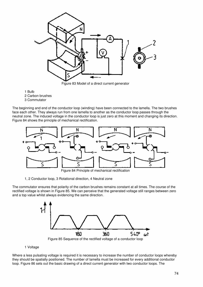
Figure 83 Model of a direct current generator
1 Bulb2 Carbon brushes3 Commutator
The beginning and end of the conductor loop (winding) have been connected to the lamella. The two brushesface each other. They always run from one lamella to another as the conductor loop passes through theneutral zone. The induced voltage in the conductor loop is just zero at this moment and changing its direction.Figure 84 shows the principle of mechanical rectification.
Figure 84 Principle of mechanical rectification
1, 2 Conductor loop, 3 Rotational direction, 4 Neutral zone
The commutator ensures that polarity of the carbon brushes remains constant at all times. The course of therectified voltage is shown in Figure 85. We can perceive that the generated voltage still ranges between zeroand a top value whilst always evidencing the same direction.
Figure 85 Sequence of the rectified voltage of a conductor loop
1 Voltage
Where a less pulsating voltage is required it is necessary to increase the number of conductor loops wherebythey should be spatially positioned. The number of lamella must be increased for every additional conductorloop. Figure 86 sets out the basic drawing of a direct current generator with two conductor loops. The
74
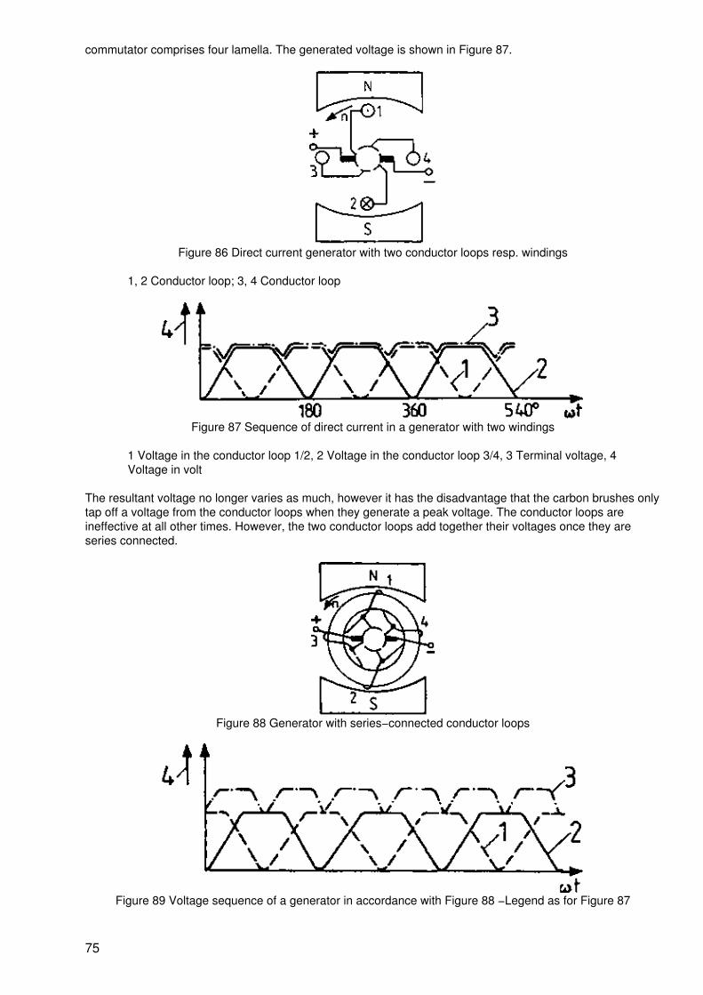
commutator comprises four lamella. The generated voltage is shown in Figure 87.
Figure 86 Direct current generator with two conductor loops resp. windings
1, 2 Conductor loop; 3, 4 Conductor loop
Figure 87 Sequence of direct current in a generator with two windings
1 Voltage in the conductor loop 1/2, 2 Voltage in the conductor loop 3/4, 3 Terminal voltage, 4Voltage in volt
The resultant voltage no longer varies as much, however it has the disadvantage that the carbon brushes onlytap off a voltage from the conductor loops when they generate a peak voltage. The conductor loops areineffective at all other times. However, the two conductor loops add together their voltages once they areseries connected.
Figure 88 Generator with series−connected conductor loops
Figure 89 Voltage sequence of a generator in accordance with Figure 88 −Legend as for Figure 87
75
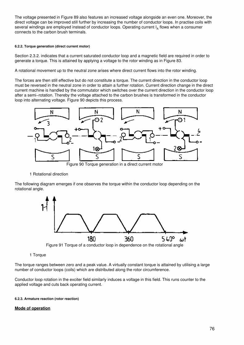
The voltage presented in Figure 89 also features an increased voltage alongside an even one. Moreover, thedirect voltage can be improved still further by increasing the number of conductor loops. In practise coils withseveral windings are employed instead of conductor loops. Operating current IA flows when a consumerconnects to the carbon brush terminals.
6.2.2. Torque generation (direct current motor)
Section 2.3.2. indicates that a current saturated conductor loop and a magnetic field are required in order togenerate a torque. This is attained by applying a voltage to the rotor winding as in Figure 83.
A rotational movement up to the neutral zone arises where direct current flows into the rotor winding.
The forces are then still effective but do not constitute a torque. The current direction in the conductor loopmust be reversed in the neutral zone in order to attain a further rotation. Current direction change in the directcurrent machine is handled by the commutator which switches over the current direction in the conductor loopafter a semi−rotation. Thereby the voltage attached to the carbon brushes is transformed in the conductorloop into alternating voltage. Figure 90 depicts this process.
Figure 90 Torque generation in a direct current motor
1 Rotational direction
The following diagram emerges if one observes the torque within the conductor loop depending on therotational angle.
Figure 91 Torque of a conductor loop in dependence on the rotational angle
1 Torque
The torque ranges between zero and a peak value. A virtually constant torque is attained by utilising a largenumber of conductor loops (coils) which are distributed along the rotor circumference.
Conductor loop rotation in the exciter field similarly induces a voltage in this field. This runs counter to theapplied voltage and cuts back operating current.
6.2.3. Armature reaction (rotor reaction)
Mode of operation
76
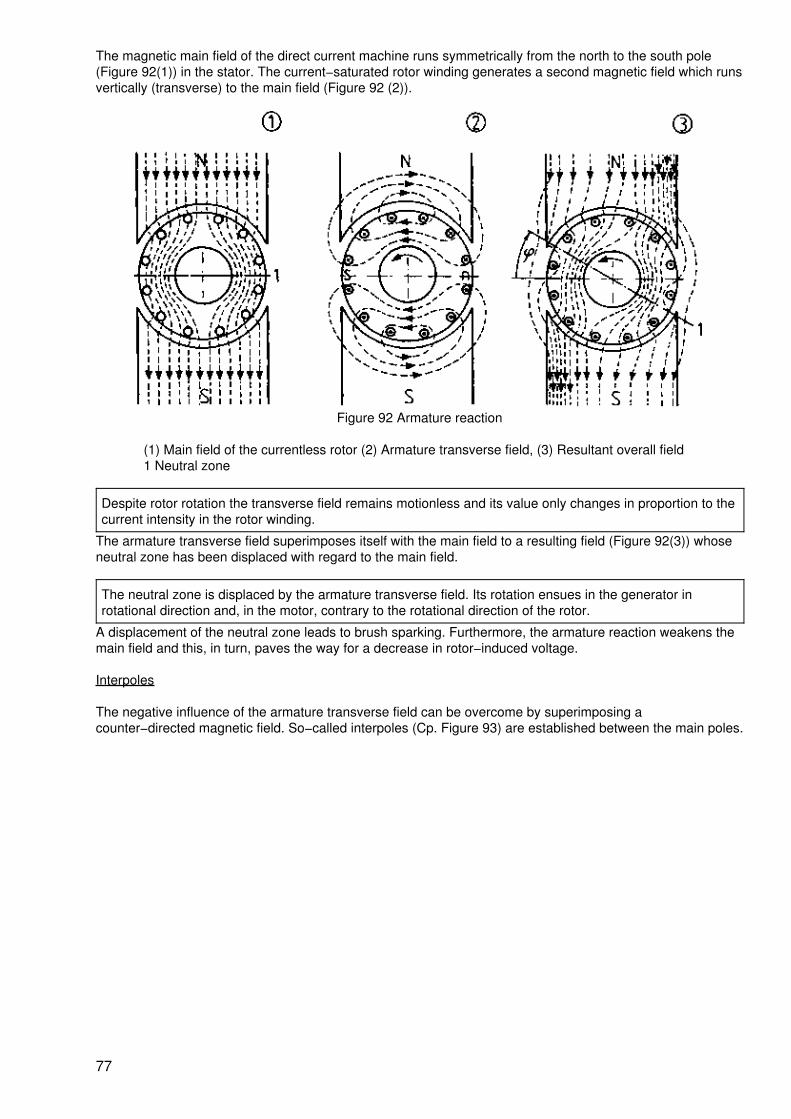
The magnetic main field of the direct current machine runs symmetrically from the north to the south pole(Figure 92(1)) in the stator. The current−saturated rotor winding generates a second magnetic field which runsvertically (transverse) to the main field (Figure 92 (2)).
Figure 92 Armature reaction
(1) Main field of the currentless rotor (2) Armature transverse field, (3) Resultant overall field1 Neutral zone
Despite rotor rotation the transverse field remains motionless and its value only changes in proportion to thecurrent intensity in the rotor winding.
The armature transverse field superimposes itself with the main field to a resulting field (Figure 92(3)) whoseneutral zone has been displaced with regard to the main field.
The neutral zone is displaced by the armature transverse field. Its rotation ensues in the generator inrotational direction and, in the motor, contrary to the rotational direction of the rotor.
A displacement of the neutral zone leads to brush sparking. Furthermore, the armature reaction weakens themain field and this, in turn, paves the way for a decrease in rotor−induced voltage.
Interpoles
The negative influence of the armature transverse field can be overcome by superimposing acounter−directed magnetic field. So−called interpoles (Cp. Figure 93) are established between the main poles.
77
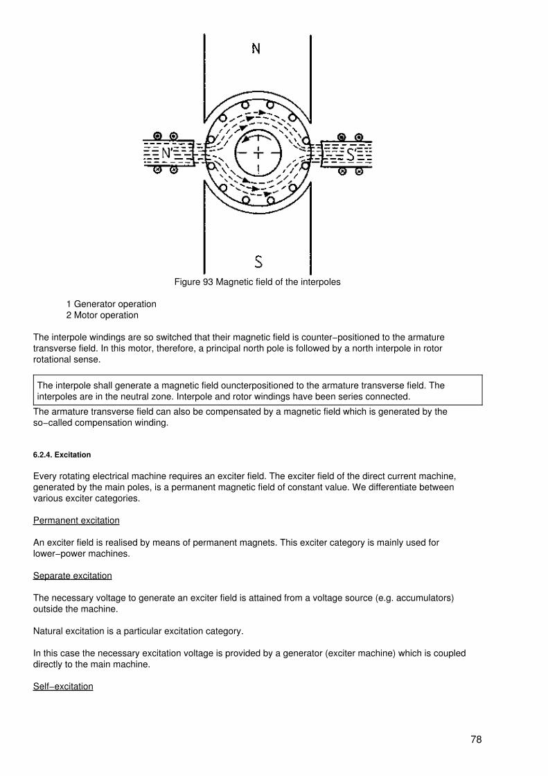
Figure 93 Magnetic field of the interpoles
1 Generator operation2 Motor operation
The interpole windings are so switched that their magnetic field is counter−positioned to the armaturetransverse field. In this motor, therefore, a principal north pole is followed by a north interpole in rotorrotational sense.
The interpole shall generate a magnetic field ouncterpositioned to the armature transverse field. Theinterpoles are in the neutral zone. Interpole and rotor windings have been series connected.
The armature transverse field can also be compensated by a magnetic field which is generated by theso−called compensation winding.
6.2.4. Excitation
Every rotating electrical machine requires an exciter field. The exciter field of the direct current machine,generated by the main poles, is a permanent magnetic field of constant value. We differentiate betweenvarious exciter categories.
Permanent excitation
An exciter field is realised by means of permanent magnets. This exciter category is mainly used forlower−power machines.
Separate excitation
The necessary voltage to generate an exciter field is attained from a voltage source (e.g. accumulators)outside the machine.
Natural excitation is a particular excitation category.
In this case the necessary excitation voltage is provided by a generator (exciter machine) which is coupleddirectly to the main machine.
Self−excitation
78
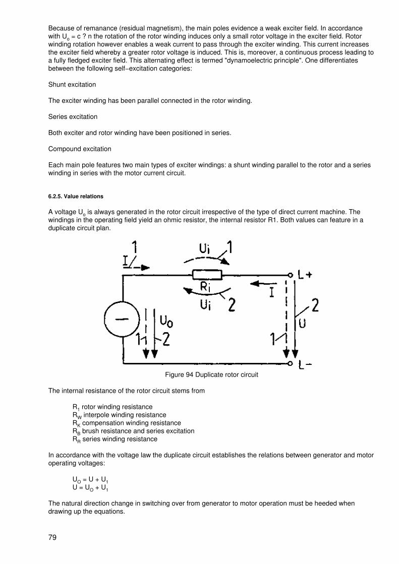
Because of remanance (residual magnetism), the main poles evidence a weak exciter field. In accordancewith Uo = c ? n the rotation of the rotor winding induces only a small rotor voltage in the exciter field. Rotorwinding rotation however enables a weak current to pass through the exciter winding. This current increasesthe exciter field whereby a greater rotor voltage is induced. This is, moreover, a continuous process leading toa fully fledged exciter field. This alternating effect is termed "dynamoelectric principle". One differentiatesbetween the following self−excitation categories:
Shunt excitation
The exciter winding has been parallel connected in the rotor winding.
Series excitation
Both exciter and rotor winding have been positioned in series.
Compound excitation
Each main pole features two main types of exciter windings: a shunt winding parallel to the rotor and a serieswinding in series with the motor current circuit.
6.2.5. Value relations
A voltage Uo is always generated in the rotor circuit irrespective of the type of direct current machine. Thewindings in the operating field yield an ohmic resistor, the internal resistor R1. Both values can feature in aduplicate circuit plan.
Figure 94 Duplicate rotor circuit
The internal resistance of the rotor circuit stems from
R1 rotor winding resistanceRW interpole winding resistanceRK compensation winding resistanceRB brush resistance and series excitationRR series winding resistance
In accordance with the voltage law the duplicate circuit establishes the relations between generator and motoroperating voltages:
UO = U + U1U = UO + U1
The natural direction change in switching over from generator to motor operation must be heeded whendrawing up the equations.
79
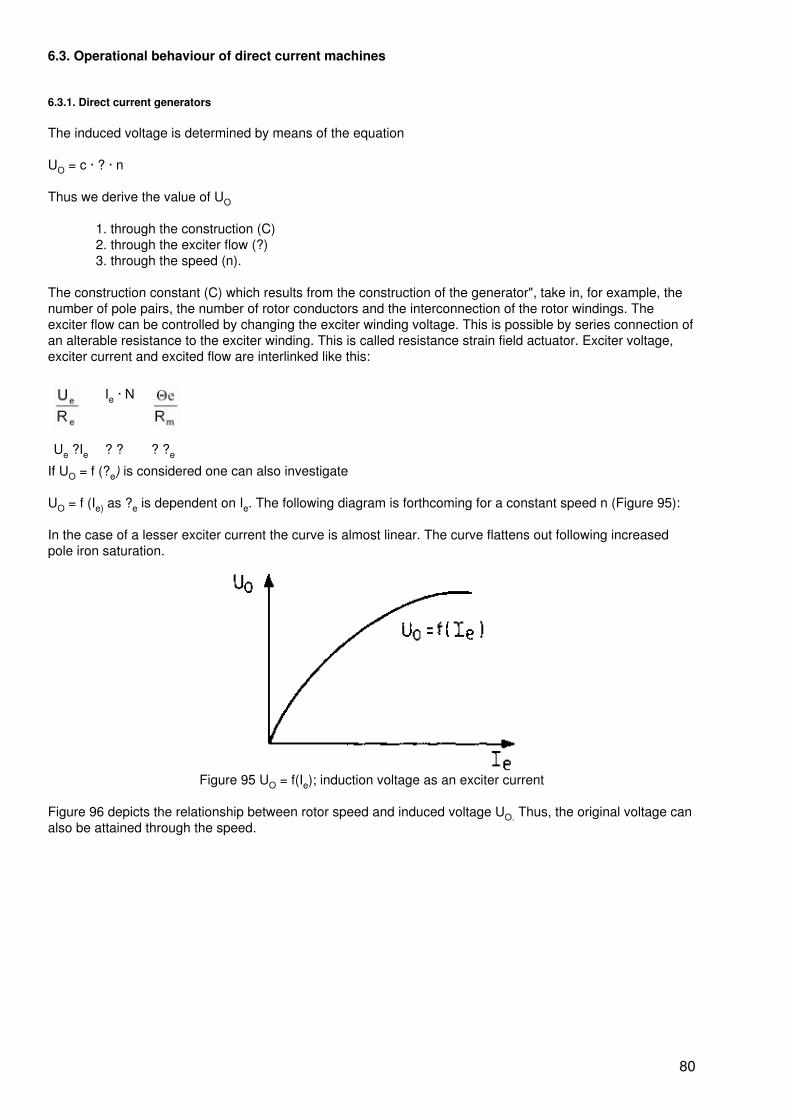
6.3. Operational behaviour of direct current machines
6.3.1. Direct current generators
The induced voltage is determined by means of the equation
UO = c · ? · n
Thus we derive the value of UO
1. through the construction (C)2. through the exciter flow (?)3. through the speed (n).
The construction constant (C) which results from the construction of the generator", take in, for example, thenumber of pole pairs, the number of rotor conductors and the interconnection of the rotor windings. Theexciter flow can be controlled by changing the exciter winding voltage. This is possible by series connection ofan alterable resistance to the exciter winding. This is called resistance strain field actuator. Exciter voltage,exciter current and excited flow are interlinked like this:
Ie · N
Ue ?Ie ? ? ? ?e
If UO = f (?e) is considered one can also investigate
UO = f (Ie) as ?e is dependent on Ie. The following diagram is forthcoming for a constant speed n (Figure 95):
In the case of a lesser exciter current the curve is almost linear. The curve flattens out following increasedpole iron saturation.
Figure 95 UO = f(Ie); induction voltage as an exciter current
Figure 96 depicts the relationship between rotor speed and induced voltage UO. Thus, the original voltage canalso be attained through the speed.
80
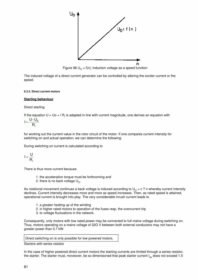
Figure 96 UO = f(n); induction voltage as a speed function
The induced voltage of a direct current generator can be controlled by altering the exciter current or thespeed.
6.3.2. Direct current motors
Starting behaviour
Direct starting
If the equation U = Uo + I Ri is adapted in line with current magnitude, one derives an equation with
for working out the current value in the rotor circuit of the motor. If one compares current intensity forswitching on and actual operation, we can determine the following:
During switching on current is calculated according to
There is thus more current because
1. the acceleration torque must be forthcoming and2. there is no back voltage UO.
As rotational movement continues a back voltage is induced according to UO = c ? n whereby current intensitydeclines. Current intensity decreases more and more as speed increases. Then, as rated speed is attained,operational current is brought into play. The very considerable inrush current leads to
1. a greater heating up of the winding2. in higher rated motors to operation of the fuses resp. the overcurrent trip3. to voltage fluctuations in the network.
Consequently, only motors with low rated power may be connected to full mains voltage during switching on.Thus, motors operating on a mains voltage of 22O V between both external conductors may not have agreater power than 0.7 kW.
Direct switching on is only possible for low powered motors.
Starters with series resistor
In the case of higher powered direct current motors the starting currents are limited through a series resistor,the starter. The starter must, moveover, be so dimensioned that peak starter current Isp does not exceed 1.5
81
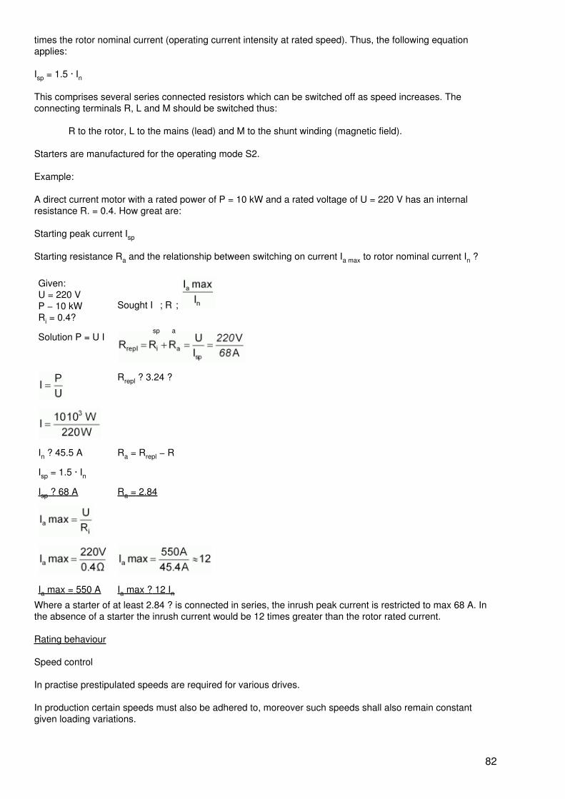
times the rotor nominal current (operating current intensity at rated speed). Thus, the following equationapplies:
Isp = 1.5 · In
This comprises several series connected resistors which can be switched off as speed increases. Theconnecting terminals R, L and M should be switched thus:
R to the rotor, L to the mains (lead) and M to the shunt winding (magnetic field).
Starters are manufactured for the operating mode S2.
Example:
A direct current motor with a rated power of P = 10 kW and a rated voltage of U = 220 V has an internalresistance R. = 0.4. How great are:
Starting peak current Isp
Starting resistance Ra and the relationship between switching on current Ia max to rotor nominal current In ?
Given:U = 220 VP − 10 kWRi = 0.4?
Sought I
sp
; R
a
;
Solution P = U I
Rrepl ? 3.24 ?
In ? 45.5 A Ra = Rrepl − R
Isp = 1.5 · In
Isp ? 68 A Ra = 2.84
Ia max = 550 A Ia max ? 12 InWhere a starter of at least 2.84 ? is connected in series, the inrush peak current is restricted to max 68 A. Inthe absence of a starter the inrush current would be 12 times greater than the rotor rated current.
Rating behaviour
Speed control
In practise prestipulated speeds are required for various drives.
In production certain speeds must also be adhered to, moreover such speeds shall also remain constantgiven loading variations.
82
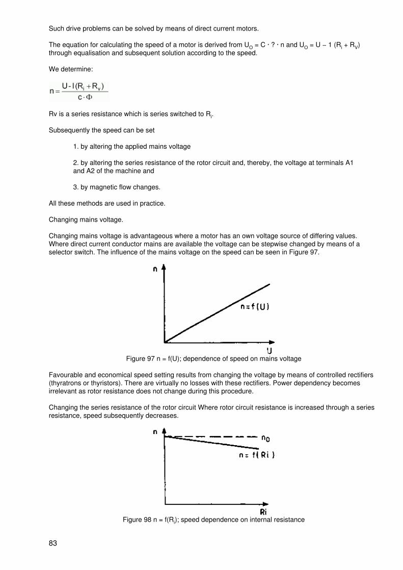
Such drive problems can be solved by means of direct current motors.
The equation for calculating the speed of a motor is derived from UO = C · ? · n and UO = U − 1 (Ri + RV)through equalisation and subsequent solution according to the speed.
We determine:
Rv is a series resistance which is series switched to Ri.
Subsequently the speed can be set
1. by altering the applied mains voltage
2. by altering the series resistance of the rotor circuit and, thereby, the voltage at terminals A1and A2 of the machine and
3. by magnetic flow changes.
All these methods are used in practice.
Changing mains voltage.
Changing mains voltage is advantageous where a motor has an own voltage source of differing values.Where direct current conductor mains are available the voltage can be stepwise changed by means of aselector switch. The influence of the mains voltage on the speed can be seen in Figure 97.
Figure 97 n = f(U); dependence of speed on mains voltage
Favourable and economical speed setting results from changing the voltage by means of controlled rectifiers(thyratrons or thyristors). There are virtually no losses with these rectifiers. Power dependency becomesirrelevant as rotor resistance does not change during this procedure.
Changing the series resistance of the rotor circuit Where rotor circuit resistance is increased through a seriesresistance, speed subsequently decreases.
Figure 98 n = f(Ri); speed dependence on internal resistance
83
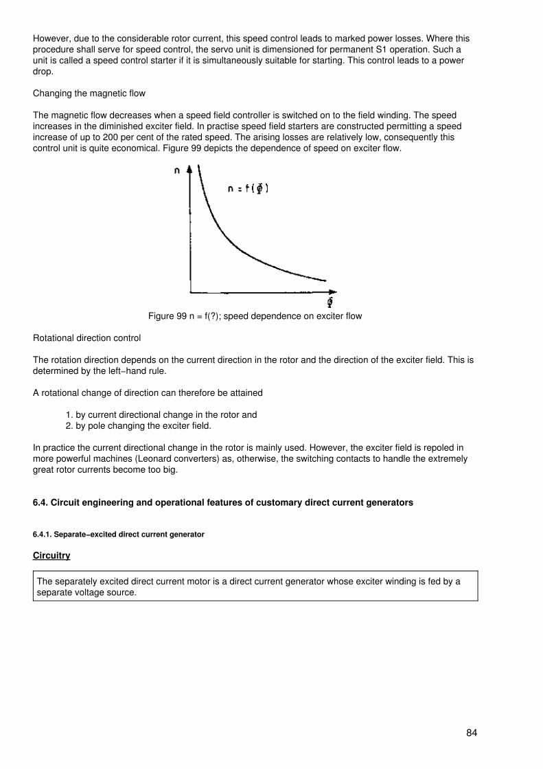
However, due to the considerable rotor current, this speed control leads to marked power losses. Where thisprocedure shall serve for speed control, the servo unit is dimensioned for permanent S1 operation. Such aunit is called a speed control starter if it is simultaneously suitable for starting. This control leads to a powerdrop.
Changing the magnetic flow
The magnetic flow decreases when a speed field controller is switched on to the field winding. The speedincreases in the diminished exciter field. In practise speed field starters are constructed permitting a speedincrease of up to 200 per cent of the rated speed. The arising losses are relatively low, consequently thiscontrol unit is quite economical. Figure 99 depicts the dependence of speed on exciter flow.
Figure 99 n = f(?); speed dependence on exciter flow
Rotational direction control
The rotation direction depends on the current direction in the rotor and the direction of the exciter field. This isdetermined by the left−hand rule.
A rotational change of direction can therefore be attained
1. by current directional change in the rotor and2. by pole changing the exciter field.
In practice the current directional change in the rotor is mainly used. However, the exciter field is repoled inmore powerful machines (Leonard converters) as, otherwise, the switching contacts to handle the extremelygreat rotor currents become too big.
6.4. Circuit engineering and operational features of customary direct current generators
6.4.1. Separate−excited direct current generator
Circuitry
The separately excited direct current motor is a direct current generator whose exciter winding is fed by aseparate voltage source.
84
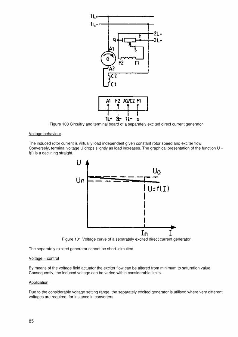
Figure 100 Circuitry and terminal board of a separately excited direct current generator
Voltage behaviour
The induced rotor current is virtually load independent given constant rotor speed and exciter flow.Conversely, terminal voltage U drops slightly as load increases. The graphical presentation of the function U =f(I) is a declining straight.
Figure 101 Voltage curve of a separately excited direct current generator
The separately excited generator cannot be short−circuited.
Voltage − control
By means of the voltage field actuator the exciter flow can be altered from minimum to saturation value.Consequently, the induced voltage can be varied within considerable limits.
Application
Due to the considerable voltage setting range, the separately excited generator is utilised where very differentvoltages are required, for instance in converters.
85
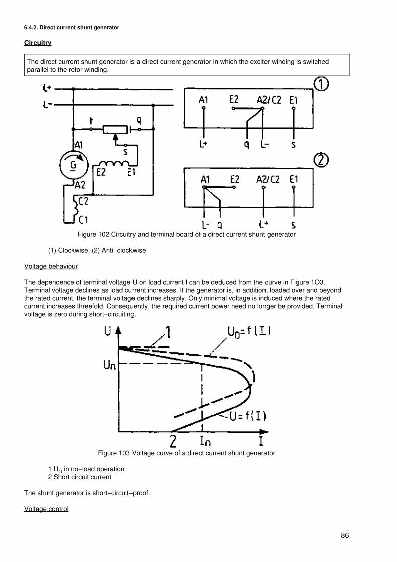
6.4.2. Direct current shunt generator
Circuitry
The direct current shunt generator is a direct current generator in which the exciter winding is switchedparallel to the rotor winding.
Figure 102 Circuitry and terminal board of a direct current shunt generator
(1) Clockwise, (2) Anti−clockwise
Voltage behaviour
The dependence of terminal voltage U on load current I can be deduced from the curve in Figure 1O3.Terminal voltage declines as load current increases. If the generator is, in addition, loaded over and beyondthe rated current, the terminal voltage declines sharply. Only minimal voltage is induced where the ratedcurrent increases threefold. Consequently, the required current power need no longer be provided. Terminalvoltage is zero during short−circuiting.
Figure 103 Voltage curve of a direct current shunt generator
1 UO in no−load operation2 Short circuit current
The shunt generator is short−circuit−proof.
Voltage control
86
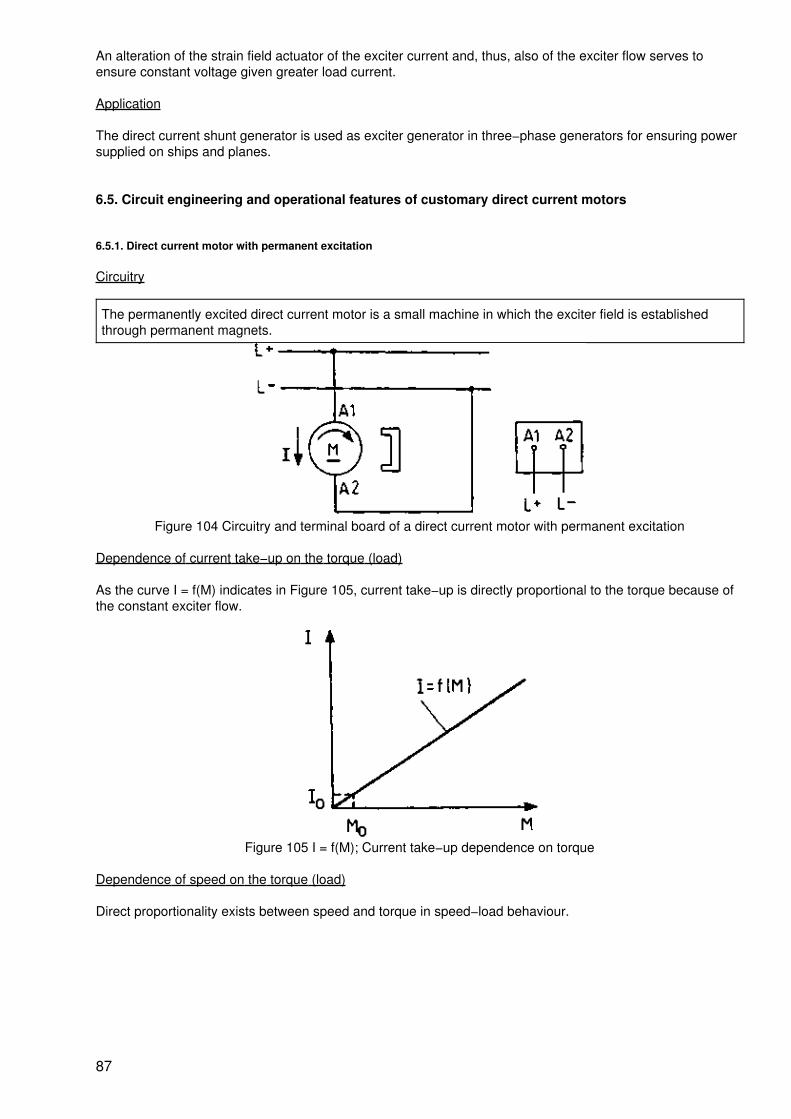
An alteration of the strain field actuator of the exciter current and, thus, also of the exciter flow serves toensure constant voltage given greater load current.
Application
The direct current shunt generator is used as exciter generator in three−phase generators for ensuring powersupplied on ships and planes.
6.5. Circuit engineering and operational features of customary direct current motors
6.5.1. Direct current motor with permanent excitation
Circuitry
The permanently excited direct current motor is a small machine in which the exciter field is establishedthrough permanent magnets.
Figure 104 Circuitry and terminal board of a direct current motor with permanent excitation
Dependence of current take−up on the torque (load)
As the curve I = f(M) indicates in Figure 105, current take−up is directly proportional to the torque because ofthe constant exciter flow.
Figure 105 I = f(M); Current take−up dependence on torque
Dependence of speed on the torque (load)
Direct proportionality exists between speed and torque in speed−load behaviour.
87
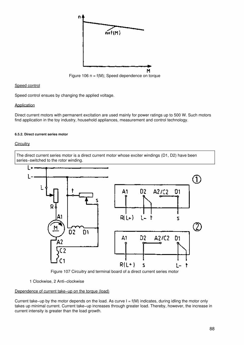
Figure 106 n = f(M); Speed dependence on torque
Speed control
Speed control ensues by changing the applied voltage.
Application
Direct current motors with permanent excitation are used mainly for power ratings up to 500 W. Such motorsfind application in the toy industry, household appliances, measurement and control technology.
6.5.2. Direct current series motor
Circuitry
The direct current series motor is a direct current motor whose exciter windings (D1, D2) have beenseries−switched to the rotor winding.
Figure 107 Circuitry and terminal board of a direct current series motor
1 Clockwise, 2 Anti−clockwise
Dependence of current take−up on the torque (load)
Current take−up by the motor depends on the load. As curve I = f(M) indicates, during idling the motor onlytakes up minimal current. Current take−up increases through greater load. Thereby, however, the increase incurrent intensity is greater than the load growth.
88
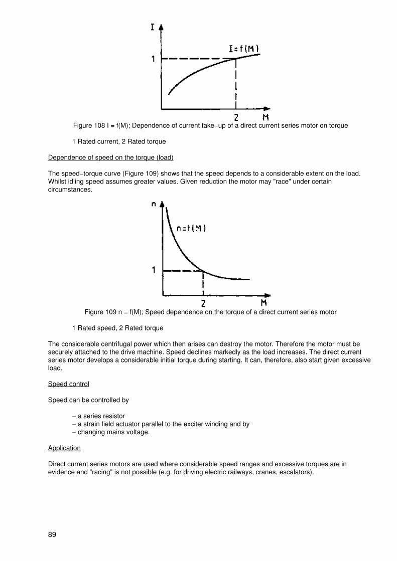
Figure 108 I = f(M); Dependence of current take−up of a direct current series motor on torque
1 Rated current, 2 Rated torque
Dependence of speed on the torque (load)
The speed−torque curve (Figure 109) shows that the speed depends to a considerable extent on the load.Whilst idling speed assumes greater values. Given reduction the motor may "race" under certaincircumstances.
Figure 109 n = f(M); Speed dependence on the torque of a direct current series motor
1 Rated speed, 2 Rated torque
The considerable centrifugal power which then arises can destroy the motor. Therefore the motor must besecurely attached to the drive machine. Speed declines markedly as the load increases. The direct currentseries motor develops a considerable initial torque during starting. It can, therefore, also start given excessiveload.
Speed control
Speed can be controlled by
− a series resistor− a strain field actuator parallel to the exciter winding and by− changing mains voltage.
Application
Direct current series motors are used where considerable speed ranges and excessive torques are inevidence and "racing" is not possible (e.g. for driving electric railways, cranes, escalators).
89
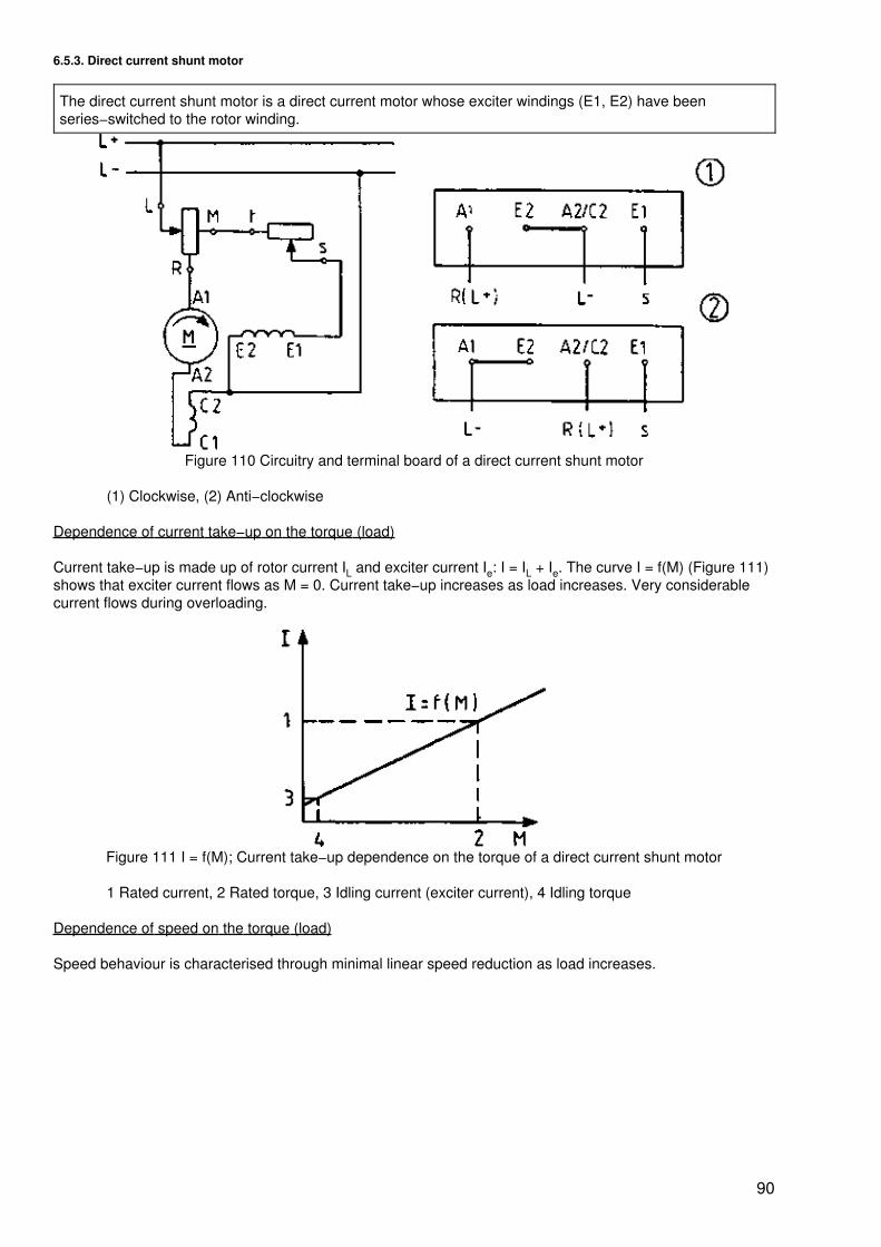
6.5.3. Direct current shunt motor
The direct current shunt motor is a direct current motor whose exciter windings (E1, E2) have beenseries−switched to the rotor winding.
Figure 110 Circuitry and terminal board of a direct current shunt motor
(1) Clockwise, (2) Anti−clockwise
Dependence of current take−up on the torque (load)
Current take−up is made up of rotor current IL and exciter current Ie: I = IL + Ie. The curve I = f(M) (Figure 111)shows that exciter current flows as M = 0. Current take−up increases as load increases. Very considerablecurrent flows during overloading.
Figure 111 I = f(M); Current take−up dependence on the torque of a direct current shunt motor
1 Rated current, 2 Rated torque, 3 Idling current (exciter current), 4 Idling torque
Dependence of speed on the torque (load)
Speed behaviour is characterised through minimal linear speed reduction as load increases.
90
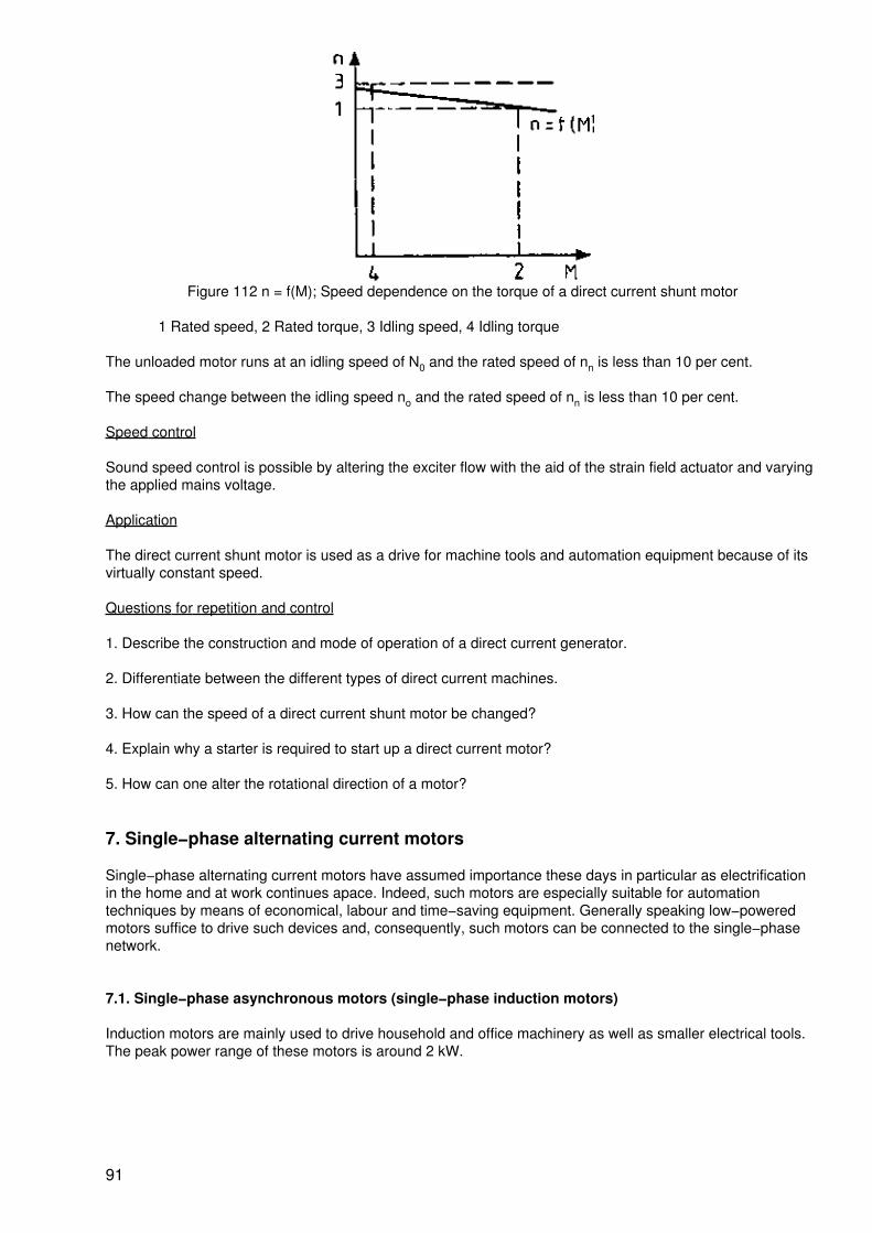
Figure 112 n = f(M); Speed dependence on the torque of a direct current shunt motor
1 Rated speed, 2 Rated torque, 3 Idling speed, 4 Idling torque
The unloaded motor runs at an idling speed of N0 and the rated speed of nn is less than 10 per cent.
The speed change between the idling speed no and the rated speed of nn is less than 10 per cent.
Speed control
Sound speed control is possible by altering the exciter flow with the aid of the strain field actuator and varyingthe applied mains voltage.
Application
The direct current shunt motor is used as a drive for machine tools and automation equipment because of itsvirtually constant speed.
Questions for repetition and control
1. Describe the construction and mode of operation of a direct current generator.
2. Differentiate between the different types of direct current machines.
3. How can the speed of a direct current shunt motor be changed?
4. Explain why a starter is required to start up a direct current motor?
5. How can one alter the rotational direction of a motor?
7. Single−phase alternating current motors
Single−phase alternating current motors have assumed importance these days in particular as electrificationin the home and at work continues apace. Indeed, such motors are especially suitable for automationtechniques by means of economical, labour and time−saving equipment. Generally speaking low−poweredmotors suffice to drive such devices and, consequently, such motors can be connected to the single−phasenetwork.
7.1. Single−phase asynchronous motors (single−phase induction motors)
Induction motors are mainly used to drive household and office machinery as well as smaller electrical tools.The peak power range of these motors is around 2 kW.
91
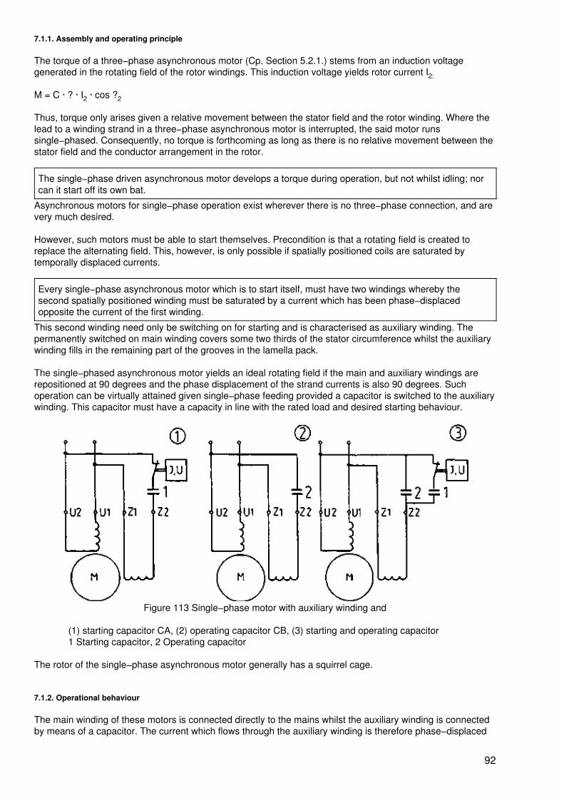
7.1.1. Assembly and operating principle
The torque of a three−phase asynchronous motor (Cp. Section 5.2.1.) stems from an induction voltagegenerated in the rotating field of the rotor windings. This induction voltage yields rotor current I2:
M = C · ? · I2 · cos ?2
Thus, torque only arises given a relative movement between the stator field and the rotor winding. Where thelead to a winding strand in a three−phase asynchronous motor is interrupted, the said motor runssingle−phased. Consequently, no torque is forthcoming as long as there is no relative movement between thestator field and the conductor arrangement in the rotor.
The single−phase driven asynchronous motor develops a torque during operation, but not whilst idling; norcan it start off its own bat.
Asynchronous motors for single−phase operation exist wherever there is no three−phase connection, and arevery much desired.
However, such motors must be able to start themselves. Precondition is that a rotating field is created toreplace the alternating field. This, however, is only possible if spatially positioned coils are saturated bytemporally displaced currents.
Every single−phase asynchronous motor which is to start itself, must have two windings whereby thesecond spatially positioned winding must be saturated by a current which has been phase−displacedopposite the current of the first winding.
This second winding need only be switching on for starting and is characterised as auxiliary winding. Thepermanently switched on main winding covers some two thirds of the stator circumference whilst the auxiliarywinding fills in the remaining part of the grooves in the lamella pack.
The single−phased asynchronous motor yields an ideal rotating field if the main and auxiliary windings arerepositioned at 90 degrees and the phase displacement of the strand currents is also 90 degrees. Suchoperation can be virtually attained given single−phase feeding provided a capacitor is switched to the auxiliarywinding. This capacitor must have a capacity in line with the rated load and desired starting behaviour.
Figure 113 Single−phase motor with auxiliary winding and
(1) starting capacitor CA, (2) operating capacitor CB, (3) starting and operating capacitor1 Starting capacitor, 2 Operating capacitor
The rotor of the single−phase asynchronous motor generally has a squirrel cage.
7.1.2. Operational behaviour
The main winding of these motors is connected directly to the mains whilst the auxiliary winding is connectedby means of a capacitor. The current which flows through the auxiliary winding is therefore phase−displaced
92
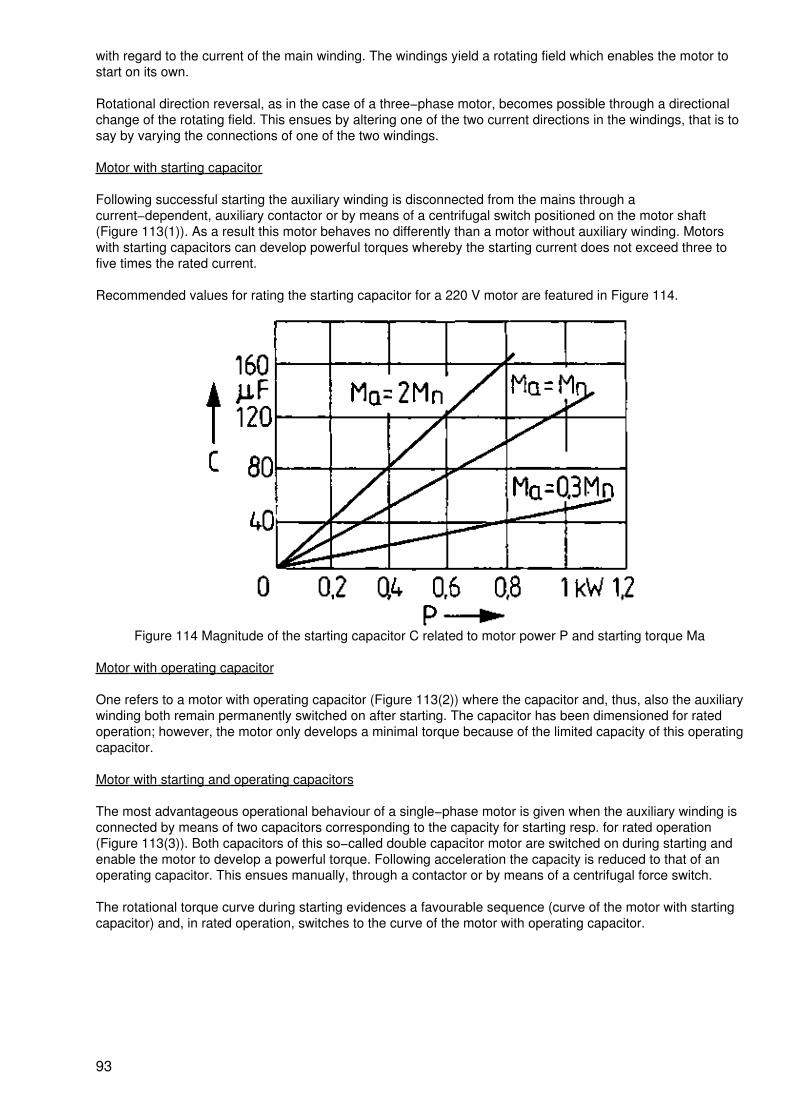
with regard to the current of the main winding. The windings yield a rotating field which enables the motor tostart on its own.
Rotational direction reversal, as in the case of a three−phase motor, becomes possible through a directionalchange of the rotating field. This ensues by altering one of the two current directions in the windings, that is tosay by varying the connections of one of the two windings.
Motor with starting capacitor
Following successful starting the auxiliary winding is disconnected from the mains through acurrent−dependent, auxiliary contactor or by means of a centrifugal switch positioned on the motor shaft(Figure 113(1)). As a result this motor behaves no differently than a motor without auxiliary winding. Motorswith starting capacitors can develop powerful torques whereby the starting current does not exceed three tofive times the rated current.
Recommended values for rating the starting capacitor for a 220 V motor are featured in Figure 114.
Figure 114 Magnitude of the starting capacitor C related to motor power P and starting torque Ma
Motor with operating capacitor
One refers to a motor with operating capacitor (Figure 113(2)) where the capacitor and, thus, also the auxiliarywinding both remain permanently switched on after starting. The capacitor has been dimensioned for ratedoperation; however, the motor only develops a minimal torque because of the limited capacity of this operatingcapacitor.
Motor with starting and operating capacitors
The most advantageous operational behaviour of a single−phase motor is given when the auxiliary winding isconnected by means of two capacitors corresponding to the capacity for starting resp. for rated operation(Figure 113(3)). Both capacitors of this so−called double capacitor motor are switched on during starting andenable the motor to develop a powerful torque. Following acceleration the capacity is reduced to that of anoperating capacitor. This ensues manually, through a contactor or by means of a centrifugal force switch.
The rotational torque curve during starting evidences a favourable sequence (curve of the motor with startingcapacitor) and, in rated operation, switches to the curve of the motor with operating capacitor.
93
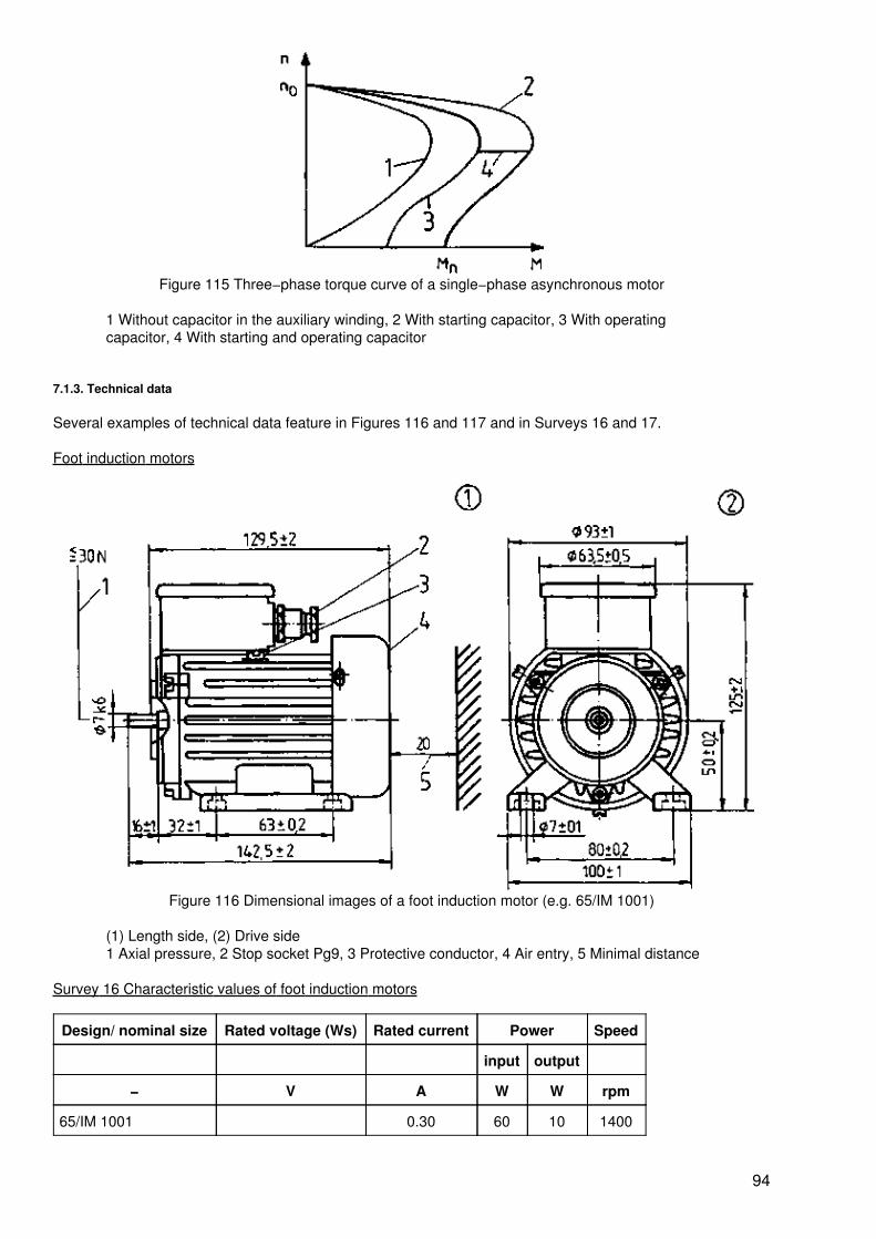
Figure 115 Three−phase torque curve of a single−phase asynchronous motor
1 Without capacitor in the auxiliary winding, 2 With starting capacitor, 3 With operatingcapacitor, 4 With starting and operating capacitor
7.1.3. Technical data
Several examples of technical data feature in Figures 116 and 117 and in Surveys 16 and 17.
Foot induction motors
Figure 116 Dimensional images of a foot induction motor (e.g. 65/IM 1001)
(1) Length side, (2) Drive side1 Axial pressure, 2 Stop socket Pg9, 3 Protective conductor, 4 Air entry, 5 Minimal distance
Survey 16 Characteristic values of foot induction motors
Design/ nominal size Rated voltage (Ws) Rated current Power Speed
input output
− V A W W rpm
65/IM 1001 0.30 60 10 1400
94
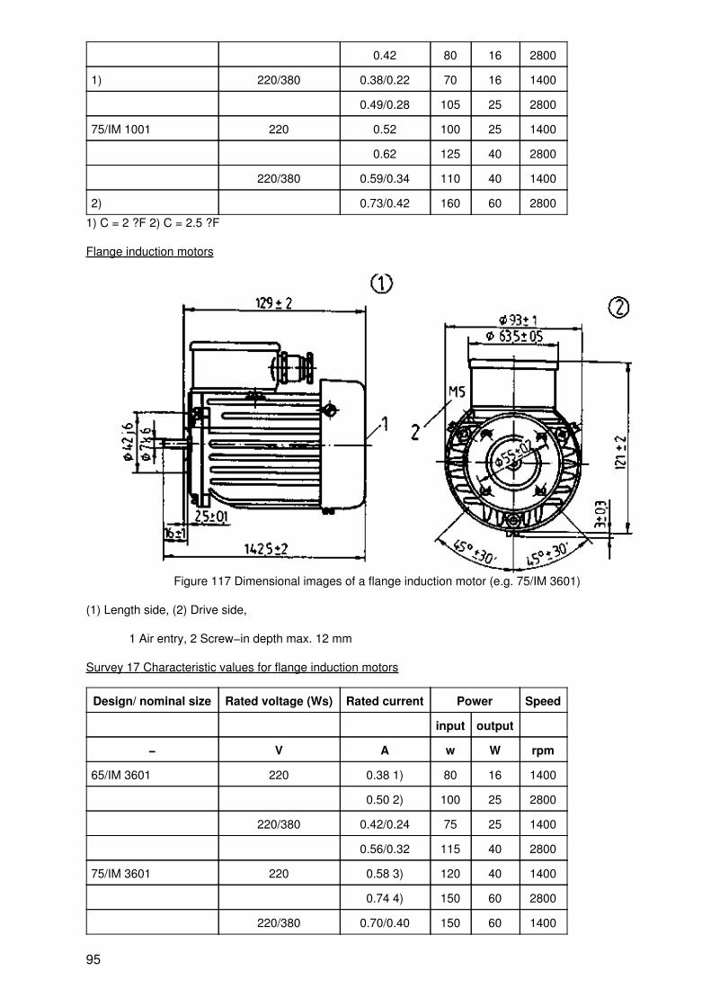
0.42 80 16 2800
1) 220/380 0.38/0.22 70 16 1400
0.49/0.28 105 25 2800
75/IM 1001 220 0.52 100 25 1400
0.62 125 40 2800
220/380 0.59/0.34 110 40 1400
2) 0.73/0.42 160 60 2800
1) C = 2 ?F 2) C = 2.5 ?F
Flange induction motors
Figure 117 Dimensional images of a flange induction motor (e.g. 75/IM 3601)
(1) Length side, (2) Drive side,
1 Air entry, 2 Screw−in depth max. 12 mm
Survey 17 Characteristic values for flange induction motors
Design/ nominal size Rated voltage (Ws) Rated current Power Speed
input output
− V A w W rpm
65/IM 3601 220 0.38 1) 80 16 1400
0.50 2) 100 25 2800
220/380 0.42/0.24 75 25 1400
0.56/0.32 115 40 2800
75/IM 3601 220 0.58 3) 120 40 1400
0.74 4) 150 60 2800
220/380 0.70/0.40 150 60 1400
95
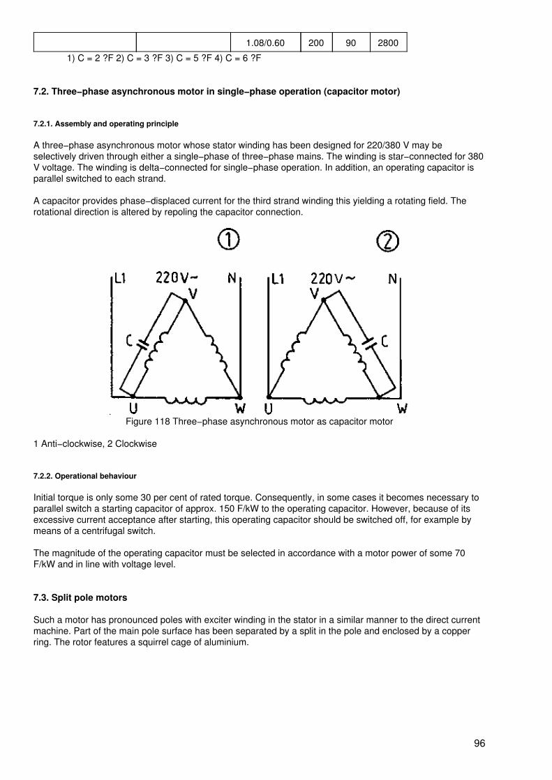
1.08/0.60 200 90 2800
1) C = 2 ?F 2) C = 3 ?F 3) C = 5 ?F 4) C = 6 ?F
7.2. Three−phase asynchronous motor in single−phase operation (capacitor motor)
7.2.1. Assembly and operating principle
A three−phase asynchronous motor whose stator winding has been designed for 220/380 V may beselectively driven through either a single−phase of three−phase mains. The winding is star−connected for 380V voltage. The winding is delta−connected for single−phase operation. In addition, an operating capacitor isparallel switched to each strand.
A capacitor provides phase−displaced current for the third strand winding this yielding a rotating field. Therotational direction is altered by repoling the capacitor connection.
Figure 118 Three−phase asynchronous motor as capacitor motor
1 Anti−clockwise, 2 Clockwise
7.2.2. Operational behaviour
Initial torque is only some 30 per cent of rated torque. Consequently, in some cases it becomes necessary toparallel switch a starting capacitor of approx. 150 F/kW to the operating capacitor. However, because of itsexcessive current acceptance after starting, this operating capacitor should be switched off, for example bymeans of a centrifugal switch.
The magnitude of the operating capacitor must be selected in accordance with a motor power of some 70F/kW and in line with voltage level.
7.3. Split pole motors
Such a motor has pronounced poles with exciter winding in the stator in a similar manner to the direct currentmachine. Part of the main pole surface has been separated by a split in the pole and enclosed by a copperring. The rotor features a squirrel cage of aluminium.
96
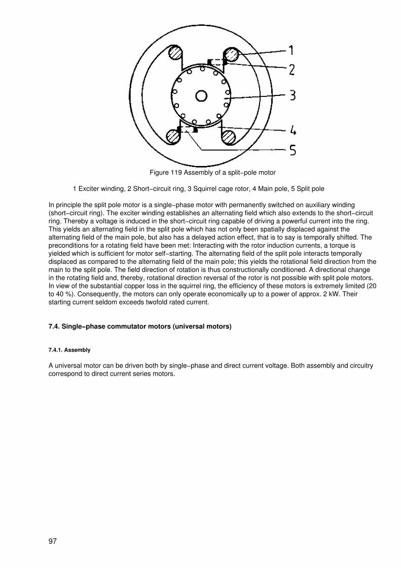
Figure 119 Assembly of a split−pole motor
1 Exciter winding, 2 Short−circuit ring, 3 Squirrel cage rotor, 4 Main pole, 5 Split pole
In principle the split pole motor is a single−phase motor with permanently switched on auxiliary winding(short−circuit ring). The exciter winding establishes an alternating field which also extends to the short−circuitring. Thereby a voltage is induced in the short−circuit ring capable of driving a powerful current into the ring.This yields an alternating field in the split pole which has not only been spatially displaced against thealternating field of the main pole, but also has a delayed action effect, that is to say is temporally shifted. Thepreconditions for a rotating field have been met: Interacting with the rotor induction currents, a torque isyielded which is sufficient for motor self−starting. The alternating field of the split pole interacts temporallydisplaced as compared to the alternating field of the main pole; this yields the rotational field direction from themain to the split pole. The field direction of rotation is thus constructionally conditioned. A directional changein the rotating field and, thereby, rotational direction reversal of the rotor is not possible with split pole motors.In view of the substantial copper loss in the squirrel ring, the efficiency of these motors is extremely limited (20to 40 %). Consequently, the motors can only operate economically up to a power of approx. 2 kW. Theirstarting current seldom exceeds twofold rated current.
7.4. Single−phase commutator motors (universal motors)
7.4.1. Assembly
A universal motor can be driven both by single−phase and direct current voltage. Both assembly and circuitrycorrespond to direct current series motors.
97
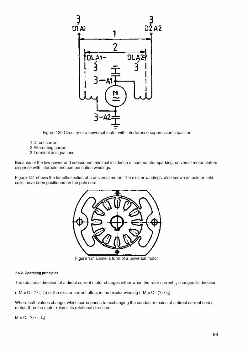
Figure 120 Circuitry of a universal motor with interference suppression capacitor
1 Direct current2 Alternating current3 Terminal designations
Because of the low power and subsequent minimal incidence of commutator sparking, universal motor statorsdispense with interpole and compensation windings.
Figure 121 shows the lamella section of a universal motor. The exciter windings, also known as pole or fieldcoils, have been positioned on the pole core.
Figure 121 Lamella form of a universal motor
7.4.2. Operating principles
The rotational direction of a direct current motor changes either when the rotor current I2 changes its direction
(−M = C · ? · (−I)) or the exciter current alters in the exciter winding (−M = C · (?) · I2).
Where both values change, which corresponds to exchanging the conductor mains of a direct current seriesmotor, then the motor retains its rotational direction:
M = C(−?) · (−I2)
98
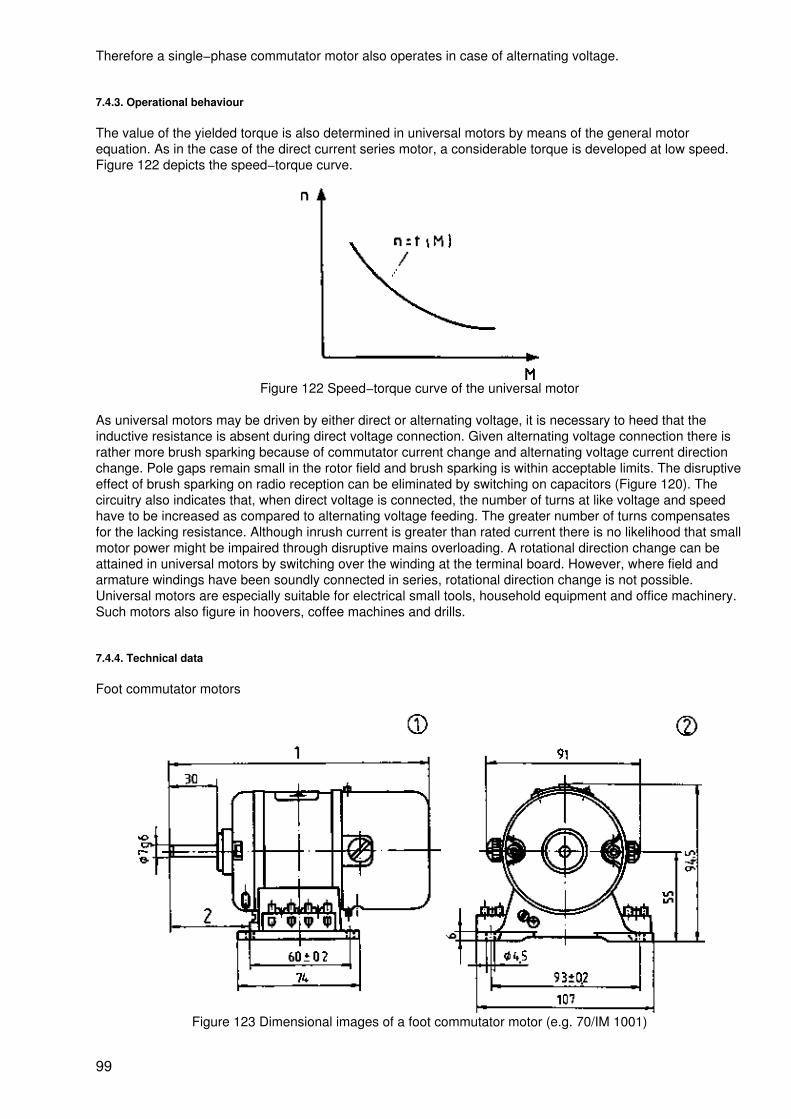
Therefore a single−phase commutator motor also operates in case of alternating voltage.
7.4.3. Operational behaviour
The value of the yielded torque is also determined in universal motors by means of the general motorequation. As in the case of the direct current series motor, a considerable torque is developed at low speed.Figure 122 depicts the speed−torque curve.
Figure 122 Speed−torque curve of the universal motor
As universal motors may be driven by either direct or alternating voltage, it is necessary to heed that theinductive resistance is absent during direct voltage connection. Given alternating voltage connection there israther more brush sparking because of commutator current change and alternating voltage current directionchange. Pole gaps remain small in the rotor field and brush sparking is within acceptable limits. The disruptiveeffect of brush sparking on radio reception can be eliminated by switching on capacitors (Figure 120). Thecircuitry also indicates that, when direct voltage is connected, the number of turns at like voltage and speedhave to be increased as compared to alternating voltage feeding. The greater number of turns compensatesfor the lacking resistance. Although inrush current is greater than rated current there is no likelihood that smallmotor power might be impaired through disruptive mains overloading. A rotational direction change can beattained in universal motors by switching over the winding at the terminal board. However, where field andarmature windings have been soundly connected in series, rotational direction change is not possible.Universal motors are especially suitable for electrical small tools, household equipment and office machinery.Such motors also figure in hoovers, coffee machines and drills.
7.4.4. Technical data
Foot commutator motors
Figure 123 Dimensional images of a foot commutator motor (e.g. 70/IM 1001)
99
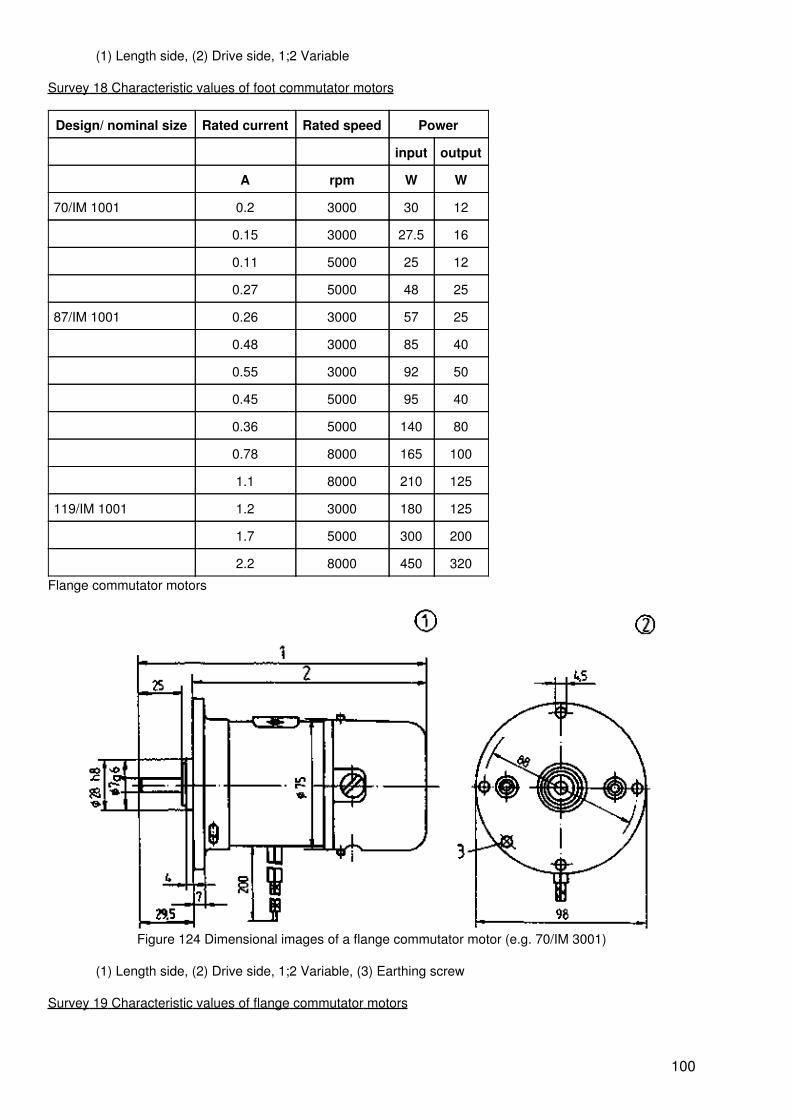
(1) Length side, (2) Drive side, 1;2 Variable
Survey 18 Characteristic values of foot commutator motors
Design/ nominal size Rated current Rated speed Power
input output
A rpm W W
70/IM 1001 0.2 3000 30 12
0.15 3000 27.5 16
0.11 5000 25 12
0.27 5000 48 25
87/IM 1001 0.26 3000 57 25
0.48 3000 85 40
0.55 3000 92 50
0.45 5000 95 40
0.36 5000 140 80
0.78 8000 165 100
1.1 8000 210 125
119/IM 1001 1.2 3000 180 125
1.7 5000 300 200
2.2 8000 450 320
Flange commutator motors
Figure 124 Dimensional images of a flange commutator motor (e.g. 70/IM 3001)
(1) Length side, (2) Drive side, 1;2 Variable, (3) Earthing screw
Survey 19 Characteristic values of flange commutator motors
100
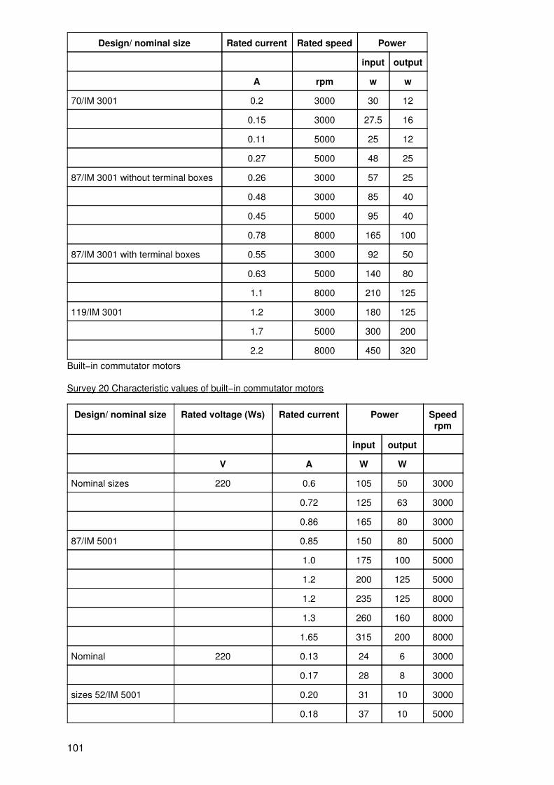
Design/ nominal size Rated current Rated speed Power
input output
A rpm w w
70/IM 3001 0.2 3000 30 12
0.15 3000 27.5 16
0.11 5000 25 12
0.27 5000 48 25
87/IM 3001 without terminal boxes 0.26 3000 57 25
0.48 3000 85 40
0.45 5000 95 40
0.78 8000 165 100
87/IM 3001 with terminal boxes 0.55 3000 92 50
0.63 5000 140 80
1.1 8000 210 125
119/IM 3001 1.2 3000 180 125
1.7 5000 300 200
2.2 8000 450 320
Built−in commutator motors
Survey 20 Characteristic values of built−in commutator motors
Design/ nominal size Rated voltage (Ws) Rated current Power Speedrpm
input output
V A W W
Nominal sizes 220 0.6 105 50 3000
0.72 125 63 3000
0.86 165 80 3000
87/IM 5001 0.85 150 80 5000
1.0 175 100 5000
1.2 200 125 5000
1.2 235 125 8000
1.3 260 160 8000
1.65 315 200 8000
Nominal 220 0.13 24 6 3000
0.17 28 8 3000
sizes 52/IM 5001 0.20 31 10 3000
0.18 37 10 5000
101
0.18 39 12 5000
0.25 47 16 5000
0.24 49 16 8000
0.30 55 20 8000
0.29 58 25 8000
Questions for repetition and control
1. How does a single−phase induction motor generate its rotating field?
2. Explain the operation of a three−phase asynchronous motor through a single−phase mains.
3. Explain the efficiency principles of the universal motor torque.
4. What must be heeded if a motor which had been connected to the alternating voltage mains, is to be drivenby direct current?
8. Transformer
8.1. Transformer principle
8.1.1. Operating principle of a transformer
Transformers are stationary electrical machines which transmit energy from systems with certain currentand voltage values into systems with generally different current and voltage values but with identicalfrequency.
Two separate windings are on the same iron core. Following connection to alternating voltage U1 there is astandstill current I. The magnetomotive force ? = I0 · N1 generates a magnetic alternating flow (?1) in the ironcore.
The input and output winding of an alternating voltage are induced in accordance with the induction law. Aself−induction voltage U10 arises in the input winding. It is counter−positioned in accordance with Lenz's lawon applied voltage. During idling operation − because of mutual induction − there arises the output voltage U20which is simultaneously the terminal voltage U2.
U1~ ? I0~ ? ?0~ ? ?1~ ? U20~
The value of the induced voltage is derived from the following equation:
UO
= 4 · 44 · f · N · · AFe
max. flow densityAFe limb cross−sectionUO induction voltagef frequencyN number of turns
The induction voltage increases along with the number of turns, the magnetic flow density in the iron core,the iron cross−section and the frequency.
Example:
Which maximum flow density occurs in an iron core of 16 cm2 cross−section when a voltage of 380 V (50 Hz)is applied to the primary coil with 930 turns?
102
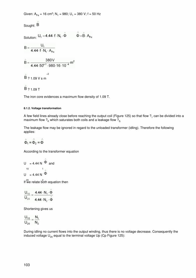
Given: AFe = 16 cm2; N1 = 980; U1 = 380 V; f = 50 Hz
Sought:
Solution:
? 1.09 V s m−2
? 1.09 T
The iron core evidences a maximum flow density of 1.09 T.
8.1.2. Voltage transformation
A few field lines already close before reaching the output coil (Figure 125) so that flow ?1 can be divided into amaximum flow ?K which saturates both coils and a leakage flow ?S.
The leakage flow may be ignored in regard to the unloaded transformer (idling). Therefore the followingapplies:
According to the transformer equation
U10
= 4.44 N1
and
U20
= 4.44 N2
If we relate both equation then
Shortening gives us
During idling no current flows into the output winding, thus there is no voltage decrease. Consequently theinduced voltage U20 equal to the terminal voltage Up (Cp Figure 125):
103
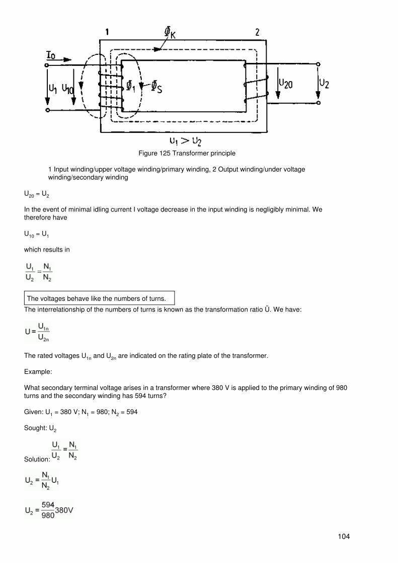
Figure 125 Transformer principle
1 Input winding/upper voltage winding/primary winding, 2 Output winding/under voltagewinding/secondary winding
U20 = U2
In the event of minimal idling current I voltage decrease in the input winding is negligibly minimal. Wetherefore have
U10 = U1
which results in
The voltages behave like the numbers of turns.
The interrelationship of the numbers of turns is known as the transformation ratio Ü. We have:
The rated voltages U1n and U2n are indicated on the rating plate of the transformer.
Example:
What secondary terminal voltage arises in a transformer where 380 V is applied to the primary winding of 980turns and the secondary winding has 594 turns?
Given: U1 = 380 V; N1 = 980; N2 = 594
Sought: U2
Solution:
104
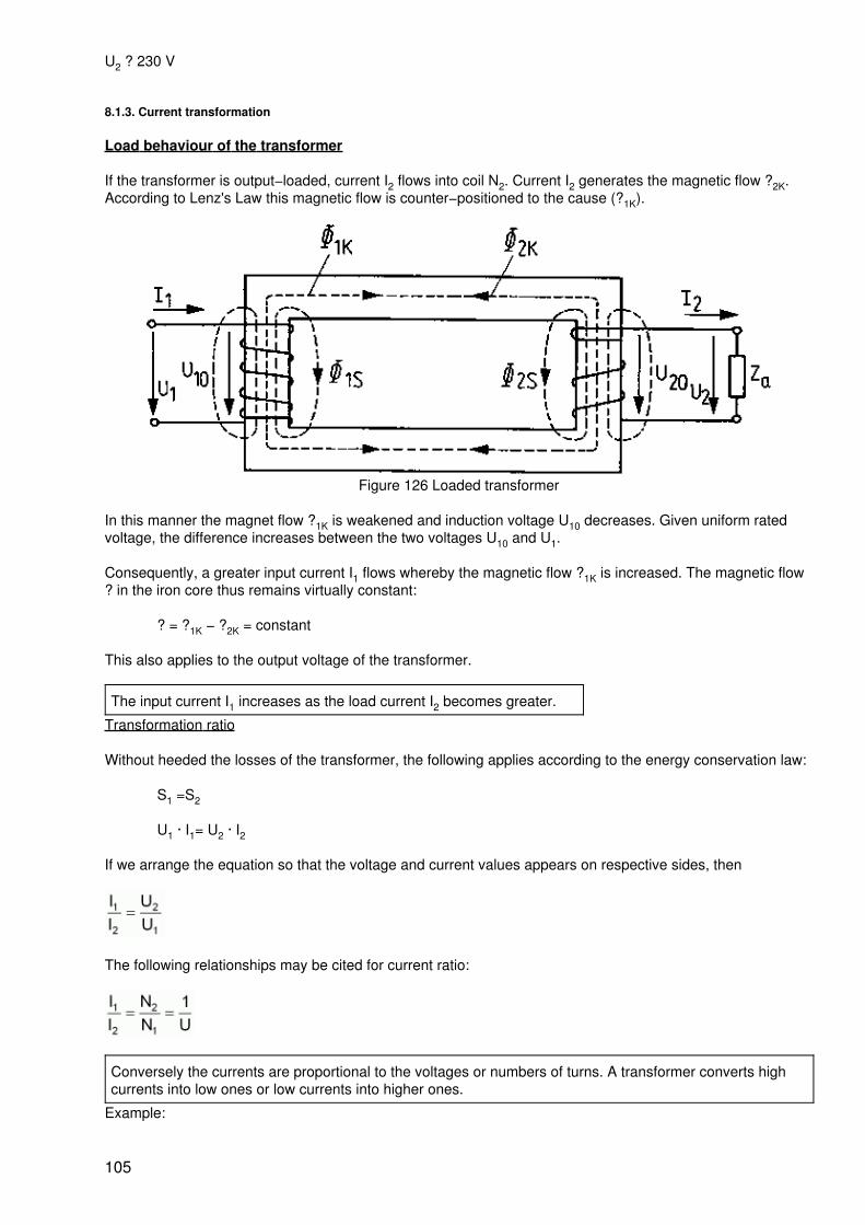
U2 ? 230 V
8.1.3. Current transformation
Load behaviour of the transformer
If the transformer is output−loaded, current I2 flows into coil N2. Current I2 generates the magnetic flow ?2K.According to Lenz's Law this magnetic flow is counter−positioned to the cause (?1K).
Figure 126 Loaded transformer
In this manner the magnet flow ?1K is weakened and induction voltage U10 decreases. Given uniform ratedvoltage, the difference increases between the two voltages U10 and U1.
Consequently, a greater input current I1 flows whereby the magnetic flow ?1K is increased. The magnetic flow? in the iron core thus remains virtually constant:
? = ?1K − ?2K = constant
This also applies to the output voltage of the transformer.
The input current I1 increases as the load current I2 becomes greater.
Transformation ratio
Without heeded the losses of the transformer, the following applies according to the energy conservation law:
S1 =S2
U1 · I1= U2 · I2
If we arrange the equation so that the voltage and current values appears on respective sides, then
The following relationships may be cited for current ratio:
Conversely the currents are proportional to the voltages or numbers of turns. A transformer converts highcurrents into low ones or low currents into higher ones.
Example:
105
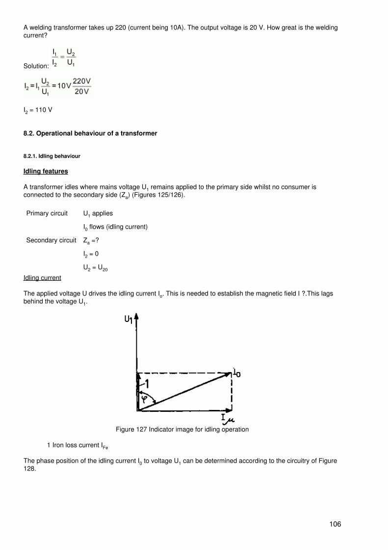
A welding transformer takes up 220 (current being 10A). The output voltage is 20 V. How great is the weldingcurrent?
Solution:
I2 = 110 V
8.2. Operational behaviour of a transformer
8.2.1. Idling behaviour
Idling features
A transformer idles where mains voltage U1 remains applied to the primary side whilst no consumer isconnected to the secondary side (Za) (Figures 125/126).
Primary circuit U1 applies
I0 flows (idling current)
Secondary circuit Za =?
I2 = 0
U2 = U20
Idling current
The applied voltage U drives the idling current Io. This is needed to establish the magnetic field I ?.This lagsbehind the voltage U1.
Figure 127 Indicator image for idling operation
1 Iron loss current IFe
The phase position of the idling current I0 to voltage U1 can be determined according to the circuitry of Figure128.
106
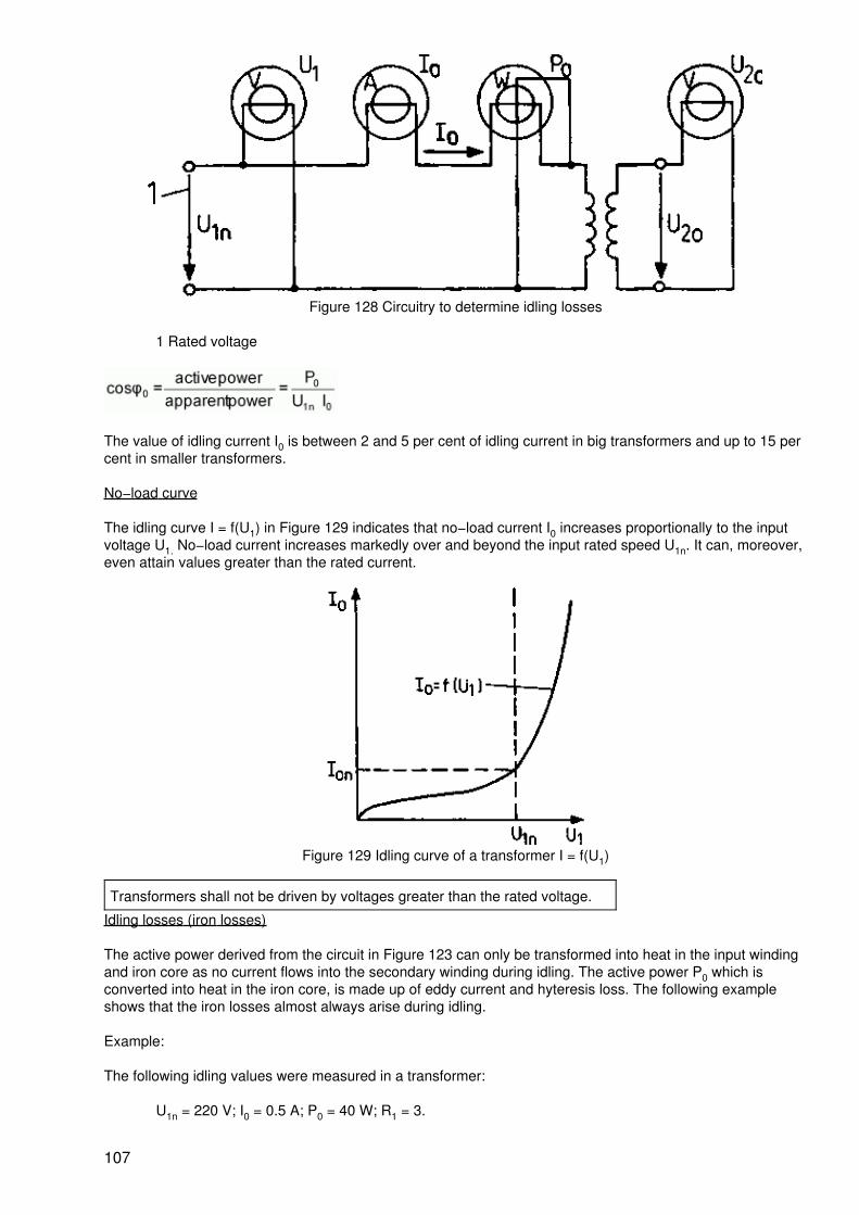
Figure 128 Circuitry to determine idling losses
1 Rated voltage
The value of idling current I0 is between 2 and 5 per cent of idling current in big transformers and up to 15 percent in smaller transformers.
No−load curve
The idling curve I = f(U1) in Figure 129 indicates that no−load current I0 increases proportionally to the inputvoltage U1. No−load current increases markedly over and beyond the input rated speed U1n. It can, moreover,even attain values greater than the rated current.
Figure 129 Idling curve of a transformer I = f(U1)
Transformers shall not be driven by voltages greater than the rated voltage.
Idling losses (iron losses)
The active power derived from the circuit in Figure 123 can only be transformed into heat in the input windingand iron core as no current flows into the secondary winding during idling. The active power P0 which isconverted into heat in the iron core, is made up of eddy current and hyteresis loss. The following exampleshows that the iron losses almost always arise during idling.
Example:
The following idling values were measured in a transformer:
U1n = 220 V; I0 = 0.5 A; P0 = 40 W; R1 = 3.
107
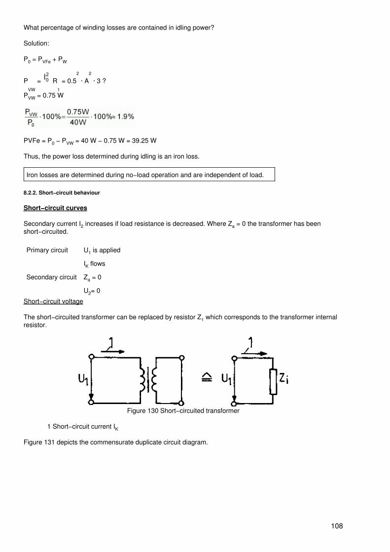
What percentage of winding losses are contained in idling power?
Solution:
P0 = PVFe + PW
PVW
= R1
= 0.52
· A2
· 3 ?
PVW = 0.75 W
PVFe = P0 − PVW = 40 W − 0.75 W = 39.25 W
Thus, the power loss determined during idling is an iron loss.
Iron losses are determined during no−load operation and are independent of load.
8.2.2. Short−circuit behaviour
Short−circuit curves
Secondary current I2 increases if load resistance is decreased. Where Za = 0 the transformer has beenshort−circuited.
Primary circuit U1 is applied
IK flows
Secondary circuit Za = 0
U2= 0
Short−circuit voltage
The short−circuited transformer can be replaced by resistor Z1 which corresponds to the transformer internalresistor.
Figure 130 Short−circuited transformer
1 Short−circuit current IK
Figure 131 depicts the commensurate duplicate circuit diagram.
108
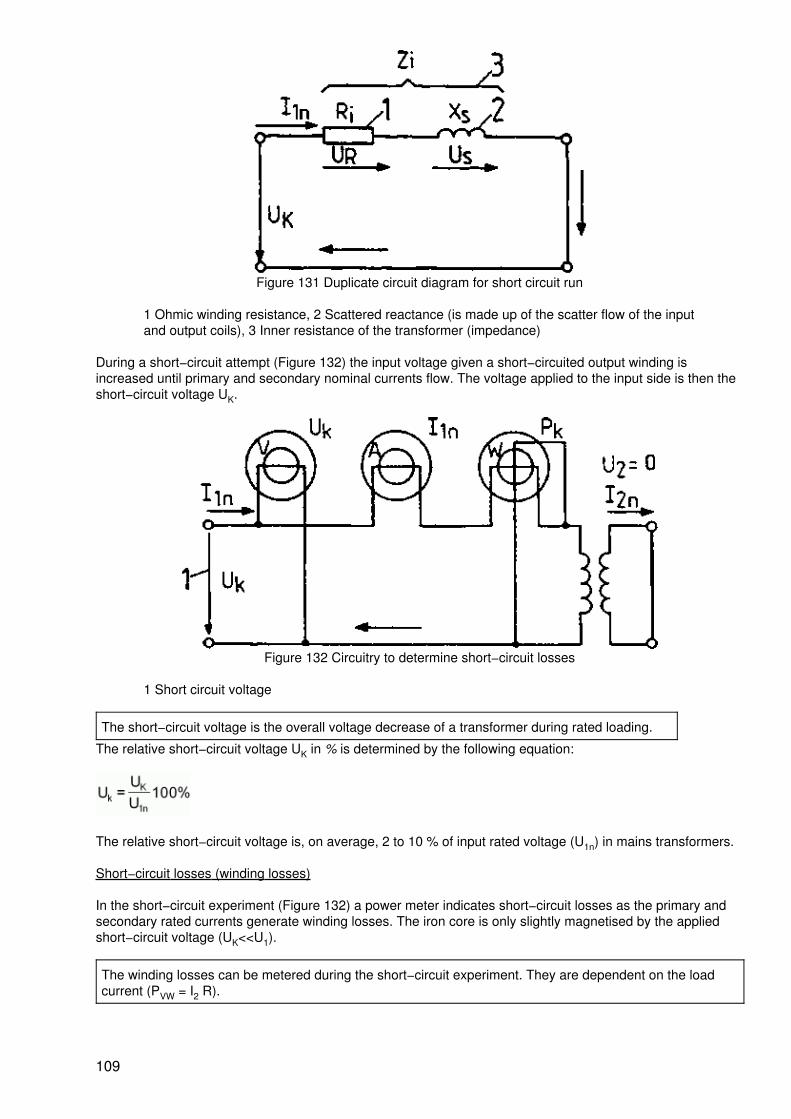
Figure 131 Duplicate circuit diagram for short circuit run
1 Ohmic winding resistance, 2 Scattered reactance (is made up of the scatter flow of the inputand output coils), 3 Inner resistance of the transformer (impedance)
During a short−circuit attempt (Figure 132) the input voltage given a short−circuited output winding isincreased until primary and secondary nominal currents flow. The voltage applied to the input side is then theshort−circuit voltage UK.
Figure 132 Circuitry to determine short−circuit losses
1 Short circuit voltage
The short−circuit voltage is the overall voltage decrease of a transformer during rated loading.
The relative short−circuit voltage UK in % is determined by the following equation:
The relative short−circuit voltage is, on average, 2 to 10 % of input rated voltage (U1n) in mains transformers.
Short−circuit losses (winding losses)
In the short−circuit experiment (Figure 132) a power meter indicates short−circuit losses as the primary andsecondary rated currents generate winding losses. The iron core is only slightly magnetised by the appliedshort−circuit voltage (UK<<U1).
The winding losses can be metered during the short−circuit experiment. They are dependent on the loadcurrent (PVW = I2 R).
109
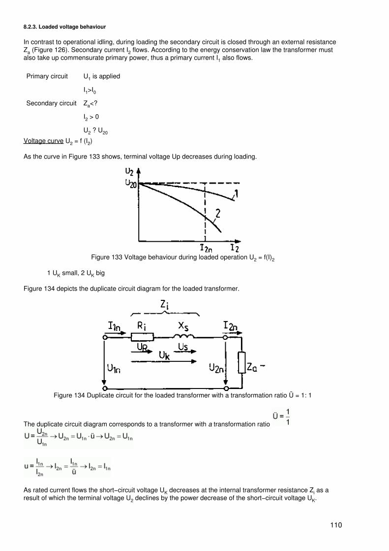
8.2.3. Loaded voltage behaviour
In contrast to operational idling, during loading the secondary circuit is closed through an external resistanceZa (Figure 126). Secondary current I2 flows. According to the energy conservation law the transformer mustalso take up commensurate primary power, thus a primary current I1 also flows.
Primary circuit U1 is applied
I1>I0
Secondary circuit Za<?
I2 > 0
U2 ? U20
Voltage curve U2 = f (I2)
As the curve in Figure 133 shows, terminal voltage Up decreases during loading.
Figure 133 Voltage behaviour during loaded operation U2 = f(I)2
1 UK small, 2 UK big
Figure 134 depicts the duplicate circuit diagram for the loaded transformer.
Figure 134 Duplicate circuit for the loaded transformer with a transformation ratio Ü = 1: 1
The duplicate circuit diagram corresponds to a transformer with a transformation ratio
As rated current flows the short−circuit voltage UK decreases at the internal transformer resistance Zi as aresult of which the terminal voltage U2 declines by the power decrease of the short−circuit voltage UK.
110
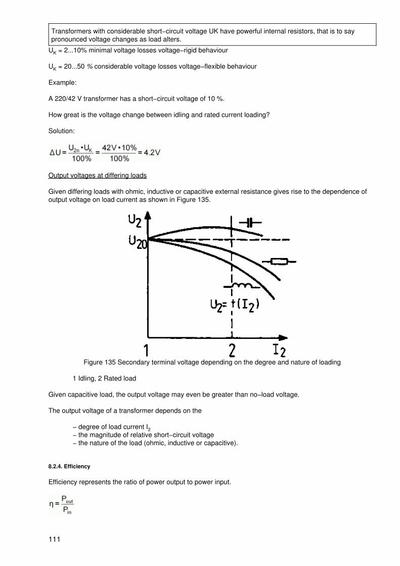
Transformers with considerable short−circuit voltage UK have powerful internal resistors, that is to saypronounced voltage changes as load alters.
UK = 2...10% minimal voltage losses voltage−rigid behaviour
UK = 20...50 % considerable voltage losses voltage−flexible behaviour
Example:
A 220/42 V transformer has a short−circuit voltage of 10 %.
How great is the voltage change between idling and rated current loading?
Solution:
Output voltages at differing loads
Given differing loads with ohmic, inductive or capacitive external resistance gives rise to the dependence ofoutput voltage on load current as shown in Figure 135.
Figure 135 Secondary terminal voltage depending on the degree and nature of loading
1 Idling, 2 Rated load
Given capacitive load, the output voltage may even be greater than no−load voltage.
The output voltage of a transformer depends on the
− degree of load current I2− the magnitude of relative short−circuit voltage− the nature of the load (ohmic, inductive or capacitive).
8.2.4. Efficiency
Efficiency represents the ratio of power output to power input.
111
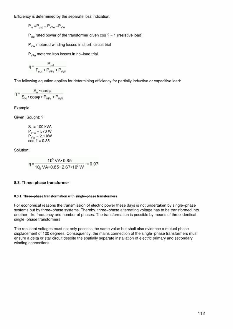
Efficiency is determined by the separate loss indication.
Pin =Pout + PVFe +PVW
Pout rated power of the transformer given cos ? = 1 (resistive load)
PVW metered winding losses in short−circuit trial
PVFe metered iron losses in no−load trial
The following equation applies for determining efficiency for partially inductive or capacitive load:
Example:
Given: Sought: ?
Sn = 100 kVAPVFe = 570 WPVW = 2.1 kWcos ? = 0.85
Solution:
8.3. Three−phase transformer
8.3.1. Three−phase transformation with single−phase transformers
For economical reasons the transmission of electric power these days is not undertaken by single−phasesystems but by three−phase systems. Thereby, three−phase alternating voltage has to be transformed intoanother, like frequency and number of phases. The transformation is possible by means of three identicalsingle−phase transformers.
The resultant voltages must not only possess the same value but shall also evidence a mutual phasedisplacement of 120 degrees. Consequently, the mains connection of the single−phase transformers mustensure a delta or star circuit despite the spatially separate installation of electric primary and secondarywinding connections.
112
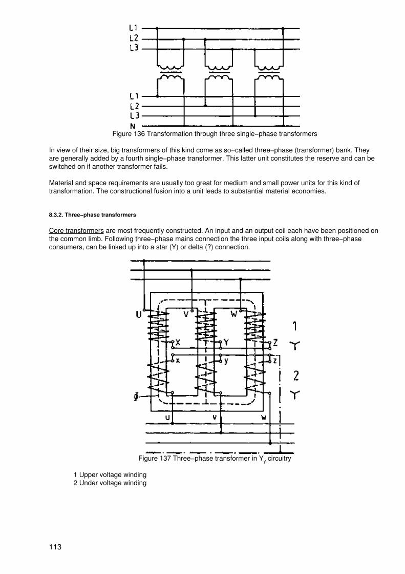
Figure 136 Transformation through three single−phase transformers
In view of their size, big transformers of this kind come as so−called three−phase (transformer) bank. Theyare generally added by a fourth single−phase transformer. This latter unit constitutes the reserve and can beswitched on if another transformer fails.
Material and space requirements are usually too great for medium and small power units for this kind oftransformation. The constructional fusion into a unit leads to substantial material economies.
8.3.2. Three−phase transformers
Core transformers are most frequently constructed. An input and an output coil each have been positioned onthe common limb. Following three−phase mains connection the three input coils along with three−phaseconsumers, can be linked up into a star (Y) or delta (?) connection.
Figure 137 Three−phase transformer in Yy circuitry
1 Upper voltage winding2 Under voltage winding
113
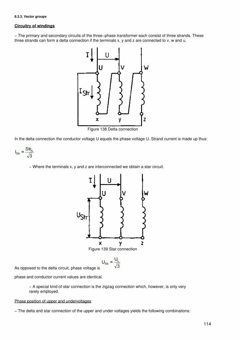
8.3.3. Vector groups
Circuitry of windings
− The primary and secondary circuits of the three−phase transformer each consist of three strands. Thesethree strands can form a delta connection if the terminals x, y and z are connected to v, w and u.
Figure 138 Delta connection
In the delta connection the conductor voltage U equals the phase voltage U. Strand current is made up thus:
− Where the terminals x, y and z are interconnected we obtain a star circuit.
Figure 139 Star connection
As opposed to the delta circuit, phase voltage is
phase and conductor current values are identical.
− A special kind of star connection is the zigzag connection which, however, is only veryrarely employed.
Phase position of upper and undervoltages
− The delta and star connection of the upper and under voltages yields the following combinations:
114
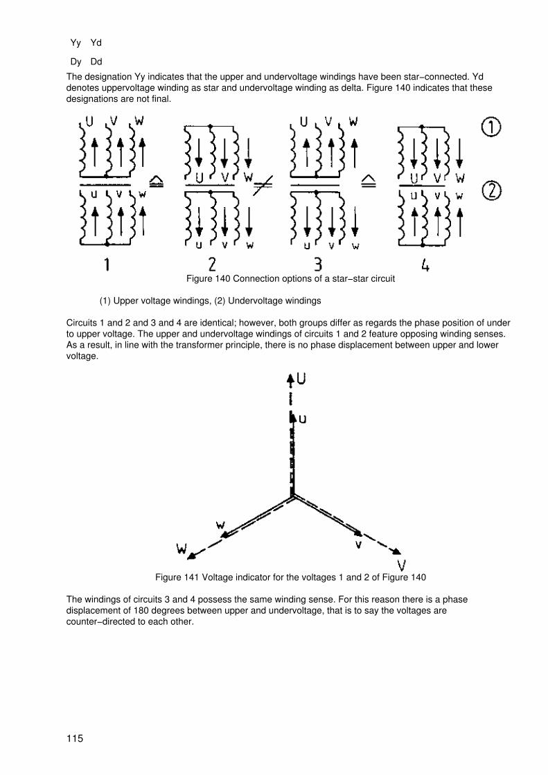
Yy Yd
Dy Dd
The designation Yy indicates that the upper and undervoltage windings have been star−connected. Yddenotes uppervoltage winding as star and undervoltage winding as delta. Figure 140 indicates that thesedesignations are not final.
Figure 140 Connection options of a star−star circuit
(1) Upper voltage windings, (2) Undervoltage windings
Circuits 1 and 2 and 3 and 4 are identical; however, both groups differ as regards the phase position of underto upper voltage. The upper and undervoltage windings of circuits 1 and 2 feature opposing winding senses.As a result, in line with the transformer principle, there is no phase displacement between upper and lowervoltage.
Figure 141 Voltage indicator for the voltages 1 and 2 of Figure 140
The windings of circuits 3 and 4 possess the same winding sense. For this reason there is a phasedisplacement of 180 degrees between upper and undervoltage, that is to say the voltages arecounter−directed to each other.
115
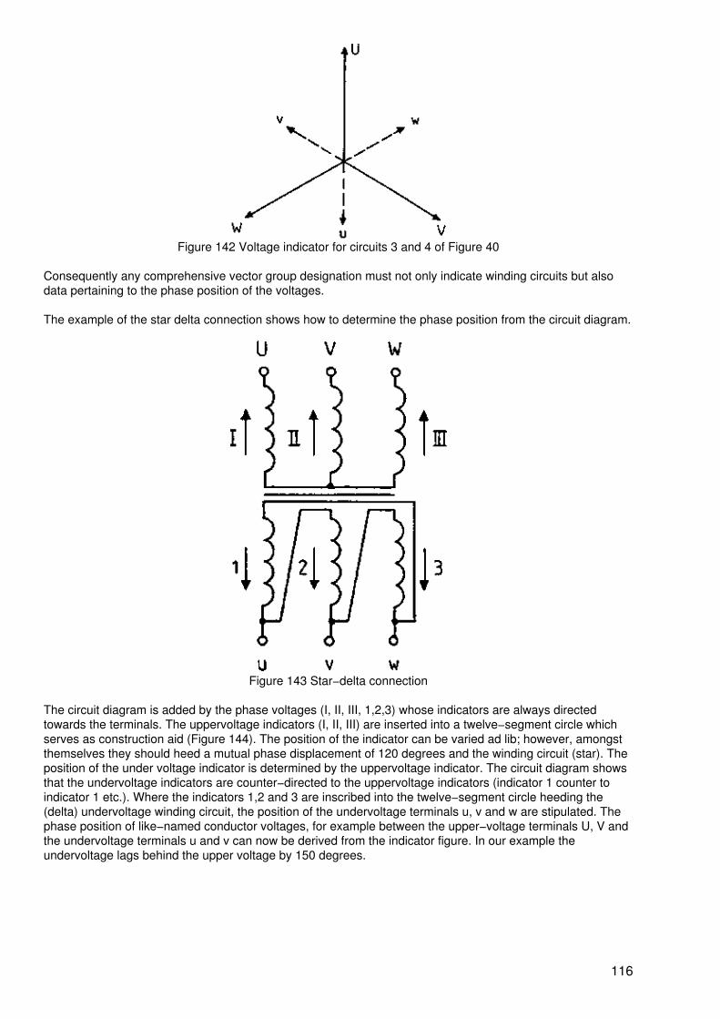
Figure 142 Voltage indicator for circuits 3 and 4 of Figure 40
Consequently any comprehensive vector group designation must not only indicate winding circuits but alsodata pertaining to the phase position of the voltages.
The example of the star delta connection shows how to determine the phase position from the circuit diagram.
Figure 143 Star−delta connection
The circuit diagram is added by the phase voltages (I, II, III, 1,2,3) whose indicators are always directedtowards the terminals. The uppervoltage indicators (I, II, III) are inserted into a twelve−segment circle whichserves as construction aid (Figure 144). The position of the indicator can be varied ad lib; however, amongstthemselves they should heed a mutual phase displacement of 120 degrees and the winding circuit (star). Theposition of the under voltage indicator is determined by the uppervoltage indicator. The circuit diagram showsthat the undervoltage indicators are counter−directed to the uppervoltage indicators (indicator 1 counter toindicator 1 etc.). Where the indicators 1,2 and 3 are inscribed into the twelve−segment circle heeding the(delta) undervoltage winding circuit, the position of the undervoltage terminals u, v and w are stipulated. Thephase position of like−named conductor voltages, for example between the upper−voltage terminals U, V andthe undervoltage terminals u and v can now be derived from the indicator figure. In our example theundervoltage lags behind the upper voltage by 150 degrees.
116
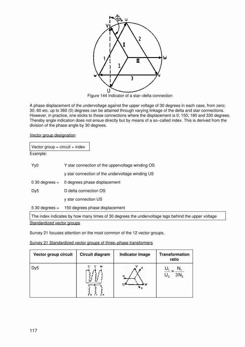
Figure 144 Indicator of a star−delta connection
A phase displacement of the undervoltage against the upper voltage of 30 degrees in each case, from zero;30; 60 etc. up to 360 (0) degrees can be attained through varying linkage of the delta and star connections.However, in practice, one sticks to those connections where the displacement is 0; 150; 180 and 330 degrees.Thereby angle indication does not ensue directly but by means of a so−called index. This is derived from thedivision of the phase angle by 30 degrees.
Vector group designation
Vector group = circuit + index
Example:
Yy0 Y star connection of the uppervoltage winding OS
y star connection of the undervoltage winding US
0 30 degrees = 0 degrees phase displacement
Dy5 D delta connection OS
y star connection US
5 30 degrees = 150 degrees phase displacement
The index indicates by how many times of 30 degrees the undervoltage lags behind the upper voltage
Standardized vector groups
Survey 21 focuses attention on the most common of the 12 vector groups.
Survey 21 Standardized vector groups of three−phase transformers
Vector group circuit Circuit diagram Indicator image Transformationratio
Dy5
117
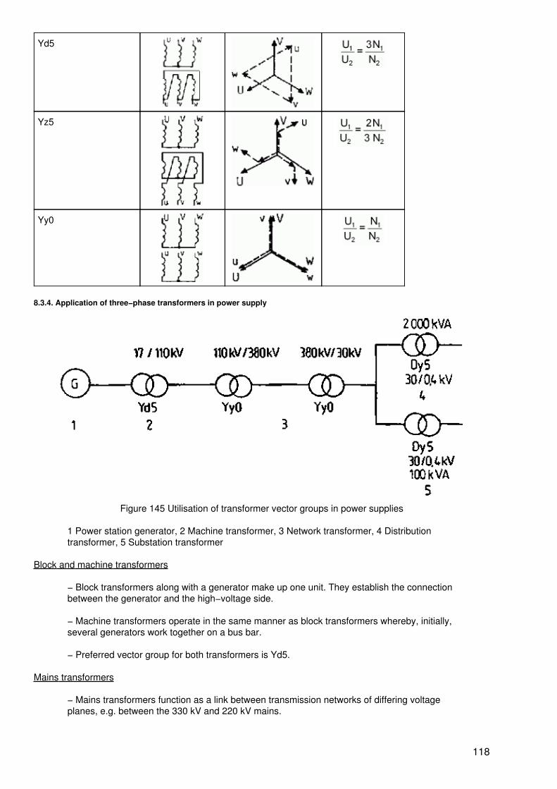
Yd5
Yz5
Yy0
8.3.4. Application of three−phase transformers in power supply
Figure 145 Utilisation of transformer vector groups in power supplies
1 Power station generator, 2 Machine transformer, 3 Network transformer, 4 Distributiontransformer, 5 Substation transformer
Block and machine transformers
− Block transformers along with a generator make up one unit. They establish the connectionbetween the generator and the high−voltage side.
− Machine transformers operate in the same manner as block transformers whereby, initially,several generators work together on a bus bar.
− Preferred vector group for both transformers is Yd5.
Mains transformers
− Mains transformers function as a link between transmission networks of differing voltageplanes, e.g. between the 330 kV and 220 kV mains.
118
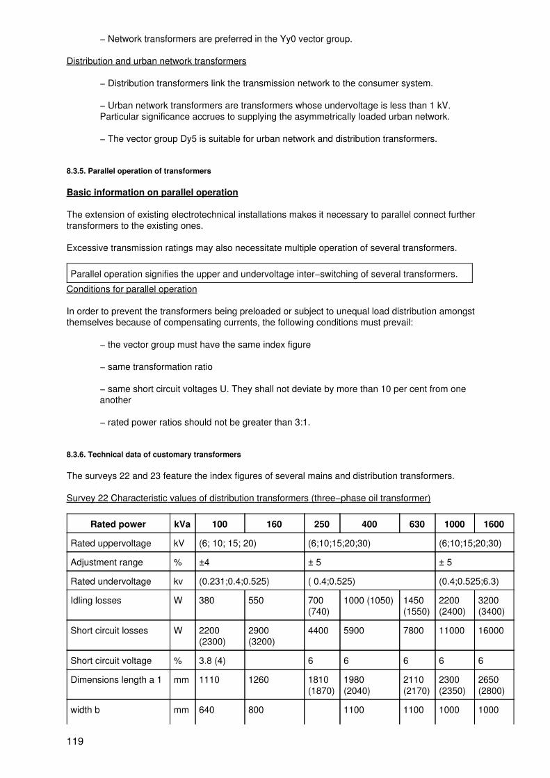
− Network transformers are preferred in the Yy0 vector group.
Distribution and urban network transformers
− Distribution transformers link the transmission network to the consumer system.
− Urban network transformers are transformers whose undervoltage is less than 1 kV.Particular significance accrues to supplying the asymmetrically loaded urban network.
− The vector group Dy5 is suitable for urban network and distribution transformers.
8.3.5. Parallel operation of transformers
Basic information on parallel operation
The extension of existing electrotechnical installations makes it necessary to parallel connect furthertransformers to the existing ones.
Excessive transmission ratings may also necessitate multiple operation of several transformers.
Parallel operation signifies the upper and undervoltage inter−switching of several transformers.
Conditions for parallel operation
In order to prevent the transformers being preloaded or subject to unequal load distribution amongstthemselves because of compensating currents, the following conditions must prevail:
− the vector group must have the same index figure
− same transformation ratio
− same short circuit voltages U. They shall not deviate by more than 10 per cent from oneanother
− rated power ratios should not be greater than 3:1.
8.3.6. Technical data of customary transformers
The surveys 22 and 23 feature the index figures of several mains and distribution transformers.
Survey 22 Characteristic values of distribution transformers (three−phase oil transformer)
Rated power kVa 100 160 250 400 630 1000 1600
Rated uppervoltage kV (6; 10; 15; 20) (6;10;15;20;30) (6;10;15;20;30)
Adjustment range % ±4 ± 5 ± 5
Rated undervoltage kv (0.231;0.4;0.525) ( 0.4;0.525) (0.4;0.525;6.3)
Idling losses W 380 550 700(740)
1000 (1050) 1450(1550)
2200(2400)
3200(3400)
Short circuit losses W 2200(2300)
2900(3200)
4400 5900 7800 11000 16000
Short circuit voltage % 3.8 (4) 6 6 6 6 6
Dimensions length a 1 mm 1110 1260 1810(1870)
1980(2040)
2110(2170)
2300(2350)
2650(2800)
width b mm 640 800 1100 1100 1000 1000
119
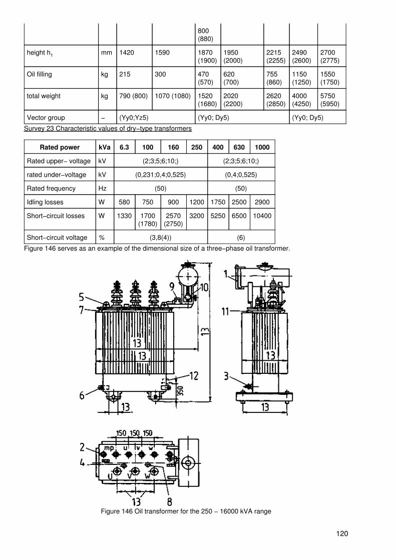
800(880)
height h1 mm 1420 1590 1870(1900)
1950(2000)
2215(2255)
2490(2600)
2700(2775)
Oil filling kg 215 300 470(570)
620(700)
755(860)
1150(1250)
1550(1750)
total weight kg 790 (800) 1070 (1080) 1520(1680)
2020(2200)
2620(2850)
4000(4250)
5750(5950)
Vector group − (Yy0;Yz5) (Yy0; Dy5) (Yy0; Dy5)
Survey 23 Characteristic values of dry−type transformers
Rated power kVa 6.3 100 160 250 400 630 1000
Rated upper− voltage kV (2;3;5;6;10;) (2;3;5;6;10;)
rated under−voltage kV (0,231;0,4;0,525) (0,4;0,525)
Rated frequency Hz (50) (50)
Idling losses W 580 750 900 1200 1750 2500 2900
Short−circuit losses W 1330 1700(1780)
2570(2750)
3200 5250 6500 10400
Short−circuit voltage % (3,8(4)) (6)
Figure 146 serves as an example of the dimensional size of a three−phase oil transformer.
Figure 146 Oil transformer for the 250 − 16000 kVA range
120

1 Oil level, 2 Thermo−pockets, 3 Oil removal device, 4 Converter, 5 Eye bolt, 6 Earthingscrew, 7,8 Oil opening, 9 Buchholz relay, 10 Stop valves (from 1000 kVA onwards), 11Shoulder hooks, 12 Hoisting points, 13 Variable dimensions
Questions for revision and control
1. Describe the basic construction and range of a transformer.
2. How can iron and winding losses be determined in a transformer?
3. How can short−circuit voltage be determined?
4. Which factors cause a voltage drop in a transformer?
5. What is the significance of the index figure in vector group data? Which index figures are cited?
6. Which are the most common vector groups and for which purposes are they used?
7. Name the parallel switching conditions.
121

122