Embed Size (px)
Citation preview
Date of Issue: October 1, 2010
By: Mr. Shannon P. Ackert
Abstract
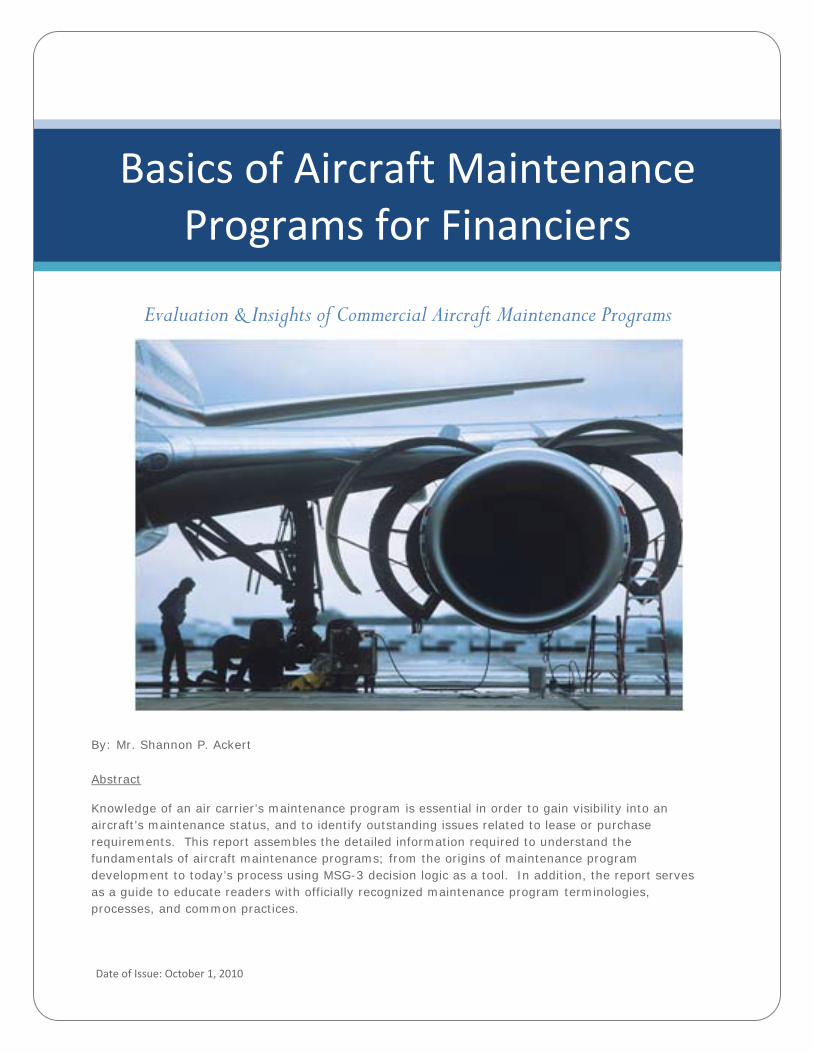
Knowledge of an air carrier’s maintenance program is essential in order to gain visibility into an aircraft’s maintenance status, and to identify outstanding issues related to lease or purchase requirements. This report assembles the detailed information required to understand the fundamentals of aircraft maintenance programs; from the origins of maintenance program development to today’s process using MSG-3 decision logic as a tool. In addition, the report serves as a guide to educate readers with officially recognized maintenance program terminologies, processes, and common practices.
Basics of Aircraft MaintenancePrograms for Financiers
Evaluation & Insights of Commercial Aircraft Maintenance Programs
1
Bas
ics
of A
ircra
ft M
aint
enan
ce P
rogr
ams
for F
inan
cier
s |
10
/1/2
01
0
Basics of Aircraft Maintenance Programs for Financiers
Evaluation & Insights of Commercial Aircraft Maintenance Programs
TABLE OF CONTENTS
1. INTRODUCTION …………………………………………………………………………………………..…………….…………… 2
2. AIRCRAFT MAINTENANCE PERSPECTIVE …………………………………………………………...……………..…..….… 22.1. Maintenance Program History ……………..……………………………………………………………..….……………… 2 2.2. Maintenance Steering Group (MSG) Processes…………………………………………..………………………………. 3
2.2.1. Maintenance Task Development …………………………………………………………………………………….. 6 2.2.2. Maintenance Program Groupings …………………………………………….……………………………………… 7
3. MAINTENANCE PROGRAM DEVELOPMENT…………………………………………….………………………….………… 73.1. Maintenance Review Board Report (MRBR) Process……….…..…………………….………………….……………… 7
3.1.1. Maintenance Review Board (MRB) ………………………………………………………………………………… 8 3.1.2. Industry Steering Committee (ISC)………………………………….……………………………..……………….. 8 3.1.3. Maintenance Working Groups (MWG)….……………..…………….……………………………………………... 8
3.2. Policy & Procedures Handbook (PPH) ………………………………………………………………………..………….. 8 3.3. Maintenance Planning Document (MPD)…………………………………….……………………….……………………. 9
3.3.1. Certification Maintenance Requirements (CMR) ………………………………………………………………….. 9 3.3.2. Airworthiness Limitations (AL) ………………………………………………………………………………………. 9
3.4. Operator Aircraft Maintenance Program (OAMP) ……………..…….…………………………………….……………… 9 3.5. Maintenance Program Supporting Documents ……………..…….……………………………………….……………… 10 3.6. Maintenance Program Enhancement Process ……………………………………………………………………………. 11 3.7. Generic versus Customized Maintenance Program……………………………………………………………………… 11
4. MAINTENANCE CHECKS.…………………..……………………….………………..……………………….………………….. 124.1. Maintenance Letter Checks ……………..…………………………………………………………..……….……………… 12 4.2. Maintenance Check Packaging………………………………………………………………….…….……………………. 14
5. MAINTENANCE STORAGE PROGRAM …………….…………………………………………………………...……..……….. 15
6. MAINTENANCE PROGRAM BRIDGING…………….……………………………………………………………………….….. 16
7. MAINTENANCE PROGRAM – VALUATION PERSPECTIVE…………………………………………..………………….…..17
8. APPENDIX 1 – EXAMPLE BLOCK & PHASE MAINTENANCE PROGRAM STRUCTURE……………………………….. 18
9. APPENDIX 2 – MPD TASK IDENTIFICATION………………………………………………..…………..………………..……. 19
10. APPENDIX 3 – AIRCRAFT STORAGE PROGRAM – TYPICAL ROUTINE TASKS………………………………………... 21
11. REFERENCES ……………………………………………………………………………………………….………………………. 22
12. ACKOWLEDEMENTS………………………………………………………………………………………………………………. 22
2
Bas
ics
of A
ircra
ft M
aint
enan
ce P
rogr
ams
for F
inan
cier
s |
10
/1/2
01
0
1.0 INTRODUCTION
The industry definition of maintenance generally includes those tasks required to restore or maintain an aircraft’s systems, components, and structures in an airworthy condition. Maintenance is required for three principal reasons:
Operational: To keep the aircraft in a serviceable and reliable condition so as to generate revenue.Value Retention: To maintain the current and future value of the aircraft by minimizing the physical deterioration of the aircraft throughout its life. Regulatory Requirements: The condition and the maintenance of aircraft are regulated by the aviation authorities of the jurisdiction in which the aircraft is registered. Such requirements establish standards for repair, periodic overhauls, and alteration by requiring that the owner or operator establish an airworthiness maintenance and inspection program to be carried out by certified individuals qualified to issue an airworthiness certificate.
2.0 MAINTENANCE PROGRAM PERSPECTIVE
2.1 Maintenance Program History - In the early days of aviation maintenance programs were developed primarily by pilots and mechanics. They assessed an aircraft’s needs for maintenance based on their individual experiences and created programs that were simple and devoid of analysis.
The introduction of the airlines as a new method of transport demanded new regulations and broader involvement of the Regulatory Authorities in maintenance requirements. During this era not only were regulations put in place but programs were started to monitor reliability and safety.
The entry of the large jet aircraft (B707 and DC-8) in the fifties focused public attention on the need for safer and more reliable aircraft. The aircraft manufacturer became the source of maintenance program development. Time limitations were established for maintenance and the entire aircraft was periodically disassembled, overhauled, and reassembled in an effort to maintain the highest level of safety. This was the origin of the first primary maintenance process referred to as Hard-Time (HT).
Hard-time processes mandated that all components be taken out of service when they reached a specified age, expressed as the number of operating flight hours, flight cycles, calendar time, or other stress units since new or since last shop visit. Removed units were routed to repair centers and effectively zero-timed, whereby the operating age was restored to a unity of zero by means of an overhaul.
In 1960 representatives from both the FAA and the airlines formed a task force to investigate the capabilities of preventive maintenance. Two major discoveries resulted from their investigation:
1. Scheduled overhaul has little effect on the overall reliability of a complex equipment unless the equipment has a dominant failure mode, and
2. There are many items for which there is no effective application for scheduled hard-time maintenance.
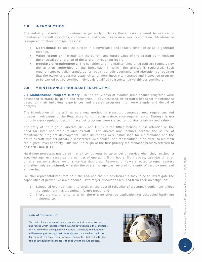
Role of Maintenance
The parts of any mechanical equipment are subject to wear, corrosion,and fatigue which inevitably result in some deviation from the conditionsthat existed when the equipment was new. Ultimately, the deviationswill become great enough that the equipment, or some item on it, nolonger meets the required performance standards – that is, it fails. Therole of scheduled maintenance is to cope with the failure process.
3
Bas
ics
of A
ircra
ft M
aint
enan
ce P
rogr
ams
for F
inan
cier
s |
10
/1/2
01
0
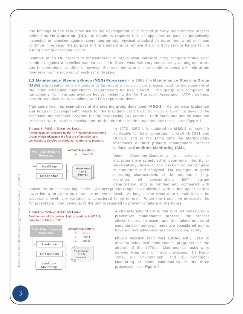
The findings of the task force led to the development of a second primary maintenance process defined as On-Condition (OC). On-Condition requires that an appliance or part be periodically inspected or checked against some appropriate physical standard to determine whether it can continue in service. The purpose of the standard is to remove the unit from service before failure during normal operation occurs.
Example of an OC process is measurement of brake wear indicator pins; compare brake wear condition against a specified standard or limit. Brake wear will vary considerably among operators due to operational conditions, however the wear indicator pin on-condition check will help attain near maximum usage out of each set of brakes.
2.2 Maintenance Steering Group (MSG) Processes - In 1968 the Maintenance Steering Group (MSG) was created with a mandate to formulate a decision logic process used for development of the initial scheduled maintenance requirements for new aircraft. The group was composed of participants from various aviation bodies, including the Air Transport Association (ATA), airlines, aircraft manufacturers, suppliers, and FAA representatives.
That same year representatives of the steering group developed “MSG-1 - Maintenance Evaluation and Program Development", which for the first time used a decision-logic diagram to develop the scheduled maintenance program for the new Boeing 747 aircraft. Both hard-time and on-condition processes were used for development of the aircraft’s routine maintenance tasks – see Figure 1.
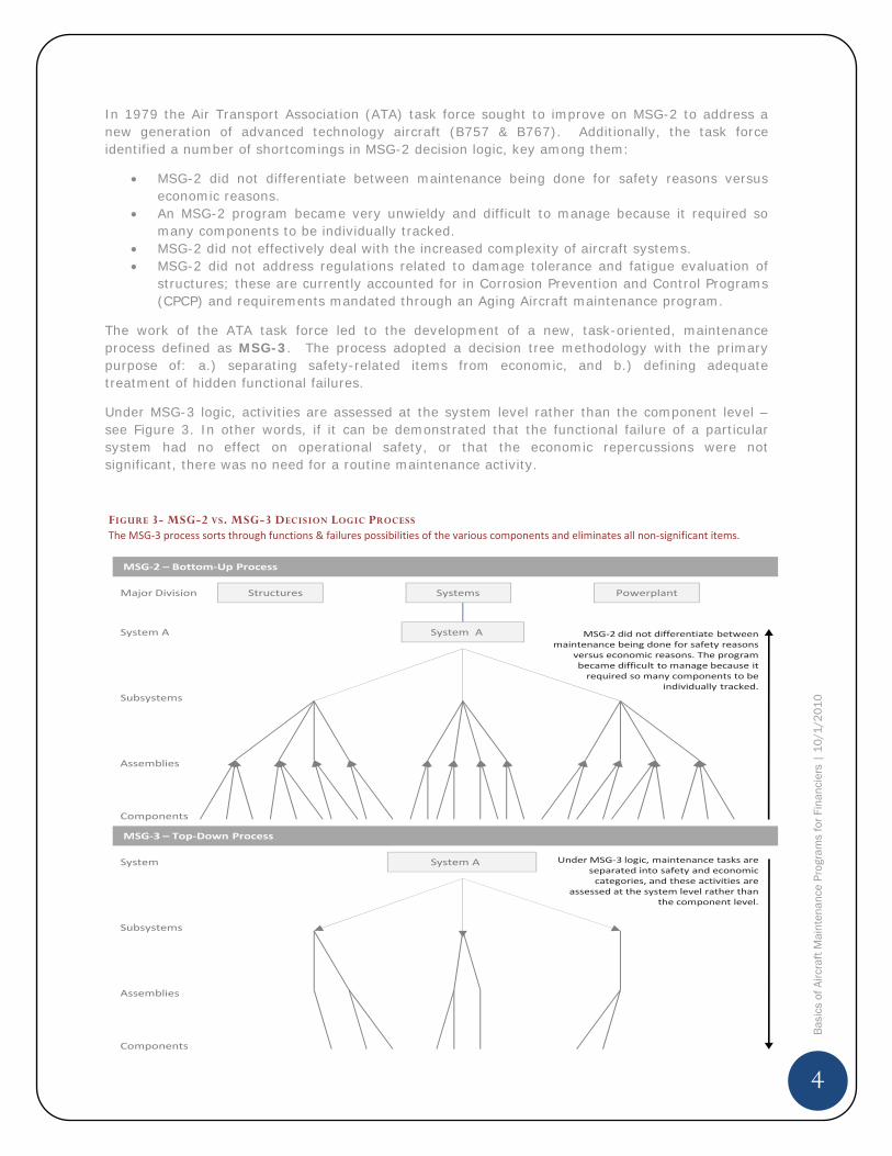
In 1970, MSG-1 is updated to MSG-2 to make it applicable for later generation aircraft (L-1011 and DC-10), and at the same time the methodology introduces a third primary maintenance process defined as Condition-Monitoring (CM).
Under Condition-Monitoring no services or inspections are scheduled to determine integrity or serviceability, however the mechanical performance is monitored and analyzed. For example, a given operating characteristic of the equipment (e.g. vibration, oil consumption, EGT margin deterioration, etc) is trended and compared with
known “normal” operating levels. An acceptable range is established with either upper and/or lower limits, or some maximum or minimum level. As long as the trend data remain inside the acceptable level, any variation is considered to be normal. When the trend line intersects the “unacceptable” limit, removal of the unit is required to prevent a failure in the future.
A characteristic of CM is that it is not considered a preventive maintenance process; the process allows failures to occur, and the failure modes of conditioned-monitored items are considered not to have a direct adverse effect on operating safety.
MSG-2 decision logic was subsequently used to develop scheduled maintenance programs for the aircraft of the 1970s. Maintenance tasks were derived from one of three processes: 1.) Hard-Time, 2.) On-Condition, and 3.) Condition-Monitoring or some combination of the three processes – see Figure 2.
FIGURE 2- MSG-2 DECISION LOGIC A refinement of the decision logic procedures in MSG 1,published in March 1970.
MSG 2 MaintenanceProcesses
Hard Time
On Condition
ConditionMonitoring
MaintenanceTask &Intervals
FIGURE 1- MSG-1 DECISION LOGIC A working paper prepared by the 747 maintenance SteeringGroup, which advocated the first use of decision logictechniques to develop a scheduled maintenance program.
MSG 1 MaintenanceProcesses
Hard Time
On Condition
MaintenanceTask &Intervals
Aircraft Applications:DC 10L1011MD 80
Aircraft Applications:747 100
4
Bas
ics
of A
ircra
ft M
aint
enan
ce P
rogr
ams
for F
inan
cier
s |
10
/1/2
01
0
In 1979 the Air Transport Association (ATA) task force sought to improve on MSG-2 to address a new generation of advanced technology aircraft (B757 & B767). Additionally, the task force identified a number of shortcomings in MSG-2 decision logic, key among them:
MSG-2 did not differentiate between maintenance being done for safety reasons versus economic reasons. An MSG-2 program became very unwieldy and difficult to manage because it required so many components to be individually tracked. MSG-2 did not effectively deal with the increased complexity of aircraft systems. MSG-2 did not address regulations related to damage tolerance and fatigue evaluation of structures; these are currently accounted for in Corrosion Prevention and Control Programs (CPCP) and requirements mandated through an Aging Aircraft maintenance program.
The work of the ATA task force led to the development of a new, task-oriented, maintenance process defined as MSG-3. The process adopted a decision tree methodology with the primary purpose of: a.) separating safety-related items from economic, and b.) defining adequate treatment of hidden functional failures.
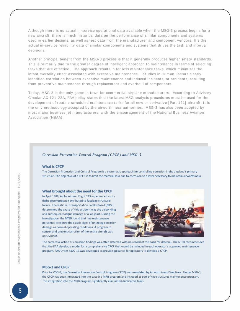
Under MSG-3 logic, activities are assessed at the system level rather than the component level – see Figure 3. In other words, if it can be demonstrated that the functional failure of a particular system had no effect on operational safety, or that the economic repercussions were not significant, there was no need for a routine maintenance activity.
FIGURE 3- MSG-2 VS. MSG-3 DECISION LOGIC PROCESS The MSG 3 process sorts through functions & failures possibilities of the various components and eliminates all non significant items.
Systems PowerplantMajor Division
Subsystems
Assemblies
Components
System A System A
Structures
Subsystems
Assemblies
Components
System System A
MSG 3 – Top Down Process
MSG 2 – Bottom Up Process
Under MSG 3 logic, maintenance tasks areseparated into safety and economiccategories, and these activities are
assessed at the system level rather thanthe component level.
MSG 2 did not differentiate betweenmaintenance being done for safety reasons
versus economic reasons. The programbecame difficult to manage because itrequired so many components to be
individually tracked.
5
Bas
ics
of A
ircra
ft M
aint
enan
ce P
rogr
ams
for F
inan
cier
s |
10
/1/2
01
0
Although there is no actual in-service operational data available when the MSG-3 process begins for a new aircraft, there is much historical data on the performance of similar components and systems used in earlier designs, as well as test data from the manufacturer and component vendors. It’s the actual in-service reliability data of similar components and systems that drives the task and interval decisions.
Another principal benefit from the MSG-3 process is that it generally produces higher safety standards. This is primarily due to the greater degree of intelligent approach to maintenance in terms of selecting tasks that are effective. The approach results in far less maintenance tasks, which minimizes the infant mortality effect associated with excessive maintenance. Studies in Human Factors clearly identified correlation between excessive maintenance and induced incidents, or accidents, resulting from preventive maintenance through replacement and overhaul of components.
Today, MSG-3 is the only game in town for commercial airplane manufacturers. According to Advisory Circular AC-121-22A, FAA policy states that the latest MSG analysis procedures must be used for the development of routine scheduled maintenance tasks for all new or derivative [Part 121] aircraft. It is the only methodology accepted by the airworthiness authorities. MSG-3 has also been adopted by most major business jet manufacturers, with the encouragement of the National Business Aviation Association (NBAA).
Corrosion Prevention Control Program (CPCP) and MSG-3
What is CPCPThe Corrosion Protection and Control Program is a systematic approach for controlling corrosion in the airplane’s primarystructure. The objective of a CPCP is to limit the material loss due to corrosion to a level necessary to maintain airworthiness.
MSG 3 and CPCPPrior to MSG 3, the Corrosion Prevention Control Program (CPCP) was mandated by Airworthiness Directives. Under MSG 3,the CPCP has been integrated into the baseline MRB program and included as part of the structures maintenance program.This integration into the MRB program significantly eliminated duplicative tasks.
What brought about the need for the CPCPIn April 1988, Aloha Airlines Flight 243 experienced an inflight decompression attributed to fuselage structuralfailure. The National Transportation Safety Board (NTSB)determined the cause of this accident was the disbondingand subsequent fatigue damage of a lap joint. During theinvestigation, the NTSB found that line maintenancepersonnel accepted the classic signs of on going corrosiondamage as normal operating conditions. A program tocontrol and prevent corrosion of the entire aircraft wasnot evident.
The corrective action of corrosion findings was often deferred with no record of the basis for deferral. The NTSB recommendedthat the FAA develop a model for a comprehensive CPCP that would be included in each operator’s approved maintenanceprogram. FAA Order 8300 12 was developed to provide guidance for operators to develop a CPCP.
6
Bas
ics
of A
ircra
ft M
aint
enan
ce P
rogr
ams
for F
inan
cier
s |
10
/1/2
01
0
2.2.1 Maintenance Task Development - MSG-3 is the current method used for developing the scheduled maintenance tasks and intervals which will be acceptable to the: a.) Regulatory authorities, b.) Operators, and c.) Manufacturers. The remaining maintenance, that is non-scheduled or non-routine maintenance, consists of maintenance actions to correct discrepancies noted during scheduled maintenance tasks.
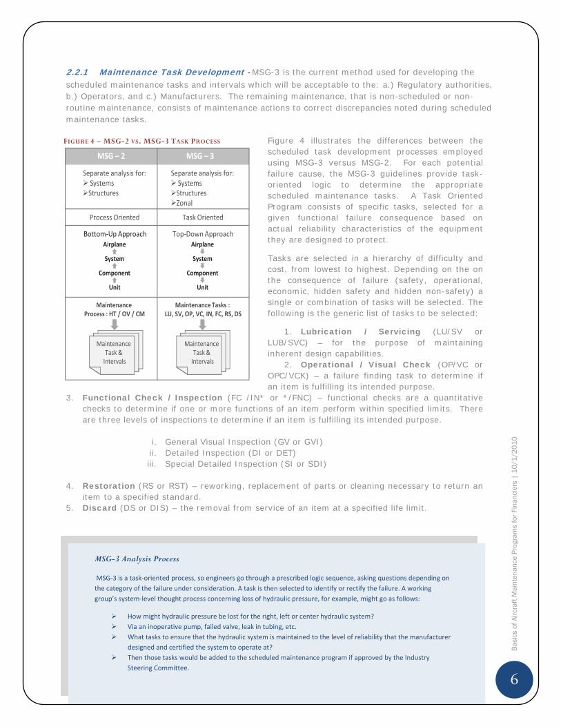
Figure 4 illustrates the differences between the scheduled task development processes employed using MSG-3 versus MSG-2. For each potential failure cause, the MSG-3 guidelines provide task-oriented logic to determine the appropriate scheduled maintenance tasks. A Task Oriented Program consists of specific tasks, selected for a given functional failure consequence based on actual reliability characteristics of the equipment they are designed to protect.
Tasks are selected in a hierarchy of difficulty and cost, from lowest to highest. Depending on the on the consequence of failure (safety, operational, economic, hidden safety and hidden non-safety) a single or combination of tasks will be selected. The following is the generic list of tasks to be selected:
1. Lubrication / Servicing (LU/SV or LUB/SVC) – for the purpose of maintaining inherent design capabilities.
2. Operational / Visual Check (OP/VC or OPC/VCK) – a failure finding task to determine if an item is fulfilling its intended purpose.
3. Functional Check / Inspection (FC /IN* or */FNC) – functional checks are a quantitative checks to determine if one or more functions of an item perform within specified limits. There are three levels of inspections to determine if an item is fulfilling its intended purpose.
i. General Visual Inspection (GV or GVI) ii. Detailed Inspection (DI or DET) iii. Special Detailed Inspection (SI or SDI)
4. Restoration (RS or RST) – reworking, replacement of parts or cleaning necessary to return an item to a specified standard.
5. Discard (DS or DIS) – the removal from service of an item at a specified life limit.
FIGURE 4 – MSG-2 VS. MSG-3 TASK PROCESS
MSG – 2
Separate analysis for:SystemsStructures
Separate analysis for:SystemsStructuresZonal
MSG – 3
Process Oriented Task Oriented
Bottom Up Approach
Unit
Component
System
AirplaneTop Down Approach
Unit
Component
System
Airplane
MaintenanceTask &Intervals
MaintenanceProcess : HT / OV / CM
MaintenanceTask &Intervals
Maintenance Tasks :LU, SV, OP, VC, IN, FC, RS, DS
MSG-3 Analysis Process
MSG 3 is a task oriented process, so engineers go through a prescribed logic sequence, asking questions depending onthe category of the failure under consideration. A task is then selected to identify or rectify the failure. A workinggroup’s system level thought process concerning loss of hydraulic pressure, for example, might go as follows:
How might hydraulic pressure be lost for the right, left or center hydraulic system?Via an inoperative pump, failed valve, leak in tubing, etc.What tasks to ensure that the hydraulic system is maintained to the level of reliability that the manufacturerdesigned and certified the system to operate at?Then those tasks would be added to the scheduled maintenance program if approved by the IndustrySteering Committee.

7
Bas
ics
of A
ircra
ft M
aint
enan
ce P
rogr
ams
for F
inan
cier
s |
10
/1/2
01
0
2.2.2 Maintenance Program Groupings - Under the MSG-3, maintenance tasks are categorized into three program groupings (see Figure 5) consisting of: a.) Systems & Powerplant, b.) Structural, and c.) Zonal
The purpose of the systems & powerplant program is to perform functional and/or operational checks on typical airplane systems i.e. flight controls, pneumatics, electrical power, etc.
The purpose of the zonal inspection program is to assess the general condition of attachment of all systems and structures items contained in each zone by use of defined zonal inspection tasks. The zonal inspection tasks include visual checks of electrical wiring, hydraulic tubing, water/waste plumbing, pneumatic ducting, components, fittings, brackets, etc., associated with the systems which are included within the zone boundaries.
The structural inspection program is designed to provide timely detection and repair of structural damage during commercial operations. Detection of corrosion, stress corrosion, minor damage and fatigue cracking by visual and/or NDT procedures are considered.
3.0 MAINTENANCE PROGRAM DEVELOPMENT
3.1 Maintenance Review Board Report (MRBR) -Before introduction of a new aircraft, the aircraft manufacturer - the Type Certificate (TC) holder - must prepare and submit for approval to the relevant airworthiness authorities the initial minimum scheduled maintenance requirements. These minimum scheduled requirements are outlined in the Maintenance Review Board Report (MRBR) – Figure 6.
After approval by the local regulatory authorities, the MRBR is used as a framework around which each air carrier develops its own individual maintenance program. Although maintenance programs may vary widely, the initial requirements for a particular aircraft will be the same for all.
The tasks detailed in the MRBR cannot be deleted nor can the task content be changed without approval of the MRB Chairman or appropriate national regulatory authority. However, individual task intervals may be escalated based on satisfactory substantiation by the operator, and review and approval by the local regulatory authority. Task interval parameters expressed in the MRB Report can also be converted to an individual operator’s desired units, provided this conversion does no result in the operator exceeding the initial requirements of the MRB Report.
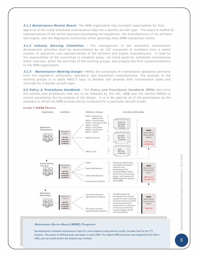
The process used by aircraft manufacturers in creating and updating the MRBR is outlined in Federal Aviation Administration Advisory Circular 121-22A (Maintenance Review Board Procedures) – see Figure 7. The process involves the establishment of a Maintenance Review Board (MRB), Industry Steering Committee (ISC) and Maintenance Working Groups (MWG). Each of these groups is composed of representatives from the participating operators, the aircraft manufacturer and the regulatory authorities. A description of each of these organizations follows.
FIGURE 6 – MRB REPORT The MRB Report contains the minimum required tasksnecessary to maintain the airworthiness of the aircraft.
MaintenanceReview Board
Report
(MRBR)
Distributed byAircraft Manufacturer
Constitutes MinimumInitial Requirements
Results fromMSG 3 Analysis
List Tasks &Intervals
FIGURE 5 – PROGRAM GROUPING
AircraftRoutineMtx
Tasks
Systems &PowerplantMtx
Program
StructuresMtxProgram
ZonalMtx Program
8
Bas
ics
of A
ircra
ft M
aint
enan
ce P
rogr
ams
for F
inan
cier
s |
10
/1/2
01
0
3.1.1 Maintenance Review Board - The MRB organization has oversight responsibility for final approval of the initial scheduled maintenance tasks for a specific aircraft type. The board is staffed by representatives of the airline operators purchasing the equipment, the manufacturers of the airframe and engine, and the Regulatory Authorities whom generally have MRB chairperson duties.
3.1.2 Industry Steering Committee - The management of the scheduled maintenance development activities shall be accomplished by an ISC composed of members from a select number of operators, and representatives of the airframe and engine manufacturers. It shall be the responsibility of this committee to establish policy, set initial goals for scheduled maintenance check intervals, direct the activities of the working groups, and prepare the final recommendations to the MRB organization.
3.1.3 Maintenance Working Groups – MWGs are composed of maintenance specialists primarily from the regulatory authorities, operators, and equipment manufacturers. The purpose of the working groups is to apply MSG-3 logic to develop and propose both maintenance tasks and intervals for a specific aircraft type.
3.2 Policy & Procedures Handbook - The Policy and Procedures Handbook (PPH) sets forth the policies and procedures that are to be followed by the ISC, MRB and the various MWGs to ensure consistency during analysis of the design. It is to be used by all of the participants as the standard to which the MRB process will be conducted for a particular aircraft model.
FIGURE 7-MRBR PROCESS
Civil Aviation AuthorityFlight Standard Inspectors
Civil Aviation AuthorityEngineering Representatives
Develop & establish policywith regard to proceduralmatters for thedevelopment of theproposed MRBR, to directthe activities of the workinggroups , and to prepare theMRBR proposal for approvalby the (MRB).
Airlines
Engine Manufacturers
Airworthiness Authorities
SystemsManufacturers
MWG 1: Hydraulics &Flight Controls
MWG 2 : EnvironmentalMWG 3 : Powerplant & APUMWG4 : AvionicsMWG 5 : Fuel SystemsMWG 6 : Landing GearMWG 7 : Interior
MWG 8: Structures
MWG 9: Zonal
Systems &PowerplantMtx Tasks& Intervals
StructuresMtx Tasks& Intervals
ZonalMtx Tasks& Intervals
MRBRMaintenanceReview Board
Report
ISC Reviewand Approval
Members / Groups Activities/ Deliverables
MaintenanceWorking Groups
Organization
MaintenanceReview Board
MRBRMaintenanceReview Board
Report
MRB Reviewand Approval
The MRB supports thedevelopment of an industryproposal for report containingthe initial minimum scheduledmaintenance/inspectionrequirements for a derivativeor newly type certificatedtransport category aircraftand its powerplants.
MRBRMaintenanceReview Board
Report
Approved
Guidelines
MaintenanceProgram
AircraftPolicy andProceduresHandbook
MaintenanceProgram
AircraftPolicy andProceduresHandbook
Industry SteeringCommittee
MaintenanceProgram
AircraftPolicy andProceduresHandbook
Maintenance Review Board (MRBR) Perspective
Developing the scheduled maintenance tasks for a new airplane is long and very costly. Consider that for the 777airplane; the project of defining tasks was begun in early 1990. The original MRB document was adopted by the FAA in1995, just two weeks before the airplane was certified.
9
Bas
ics
of A
ircra
ft M
aint
enan
ce P
rogr
ams
for F
inan
cier
s |
10
/1/2
01
0
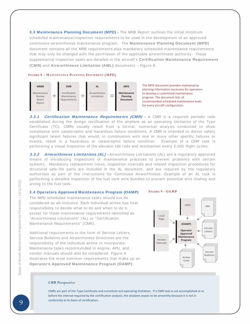
3.3 Maintenance Planning Document (MPD) - The MRB Report outlines the initial minimum scheduled maintenance/inspection requirements to be used in the development of an approved continuous airworthiness maintenance program. The Maintenance Planning Document (MPD)document contains all the MRB requirements plus mandatory scheduled maintenance requirements that may only be changed with the permission of the applicable airworthiness authority. These supplemental inspection tasks are detailed in the aircraft’s Certification Maintenance Requirement (CMR) and Airworthiness Limitation (AWL) documents – Figure 8.
3.3.1 Certification Maintenance Requirements (CMR) - A CMR is a required periodic task established during the design certification of the airplane as an operating limitation of the Type Certificate (TC). CMRs usually result from a formal, numerical analysis conducted to show compliance with catastrophic and hazardous failure conditions. A CMR is intended to detect safety significant latent failures that would, in combination with one or more other specific failures or events, result in a hazardous or catastrophic failure condition. Example of a CMR task is performing a visual inspection of the elevator tab rods and mechanism every 2,000 flight cycles.
3.3.2 Airworthiness Limitations (AL) - Airworthiness Limitations (AL) are a regulatory approved means of introducing inspections or maintenance practices to prevent problems with certain systems. Mandatory replacement times, inspection intervals and related inspection procedures for structural safe-life parts are included in the AL document, and are required by the regulatory authorities as part of the Instructions for Continued Airworthiness. Example of an AL task is performing a detailed inspection of the fuel tank wire bundles to prevent potential wire chafing and arcing to the fuel tank.
3.4 Operators Approved Maintenance Program (OAMP)The MPD scheduled maintenance tasks should not be considered as all-inclusive. Each individual airline has final responsibility to decide what to do and when to do it, except for those maintenance requirements identified as "Airworthiness Limitations" (AL) or "Certification Maintenance Requirements" (CMR).
Additional requirements in the form of Service Letters, Service Bulletins and Airworthiness Directives are the responsibility of the individual airline to incorporate. Maintenance tasks recommended in engine, APU, and vendor manuals should also be considered. Figure 9 illustrates the most common requirements that make up anOperator’s Approved Maintenance Program (OAMP).
FIGURE 9 - OAMP
MPD
ServiceBulletins
ServiceLetters
ADs
AirlineTasks
(OAMP)
OperatorApproved
MaintenanceProgramVendor
Manuals
LocalRegs
FIGURE 8 – MAINTENANCE PLANNING DOCUMENT (MPD)
MRBR
MaintenanceReviewBoardReport
CMR
CertificationMaintenanceRequirements
AL
AirworthinessLimitations
MPD
MaintenancePlanningDocument
The MPD document provides maintenanceplanning information necessary for operatorsto develop a customized maintenanceprogram. The document lists allrecommended scheduled maintenance tasksfor every aircraft configuration.
CMR Perspective
CMRs are part of the Type Certificate and constitute and operating limitation. If a CMR task is not accomplished at orbefore the interval required by the certification analysis, the airplane ceases to be airworthy because it is not inconformity to its basis of certification.
10
Bas
ics
of A
ircra
ft M
aint
enan
ce P
rogr
ams
for F
inan
cier
s |
10
/1/2
01
0
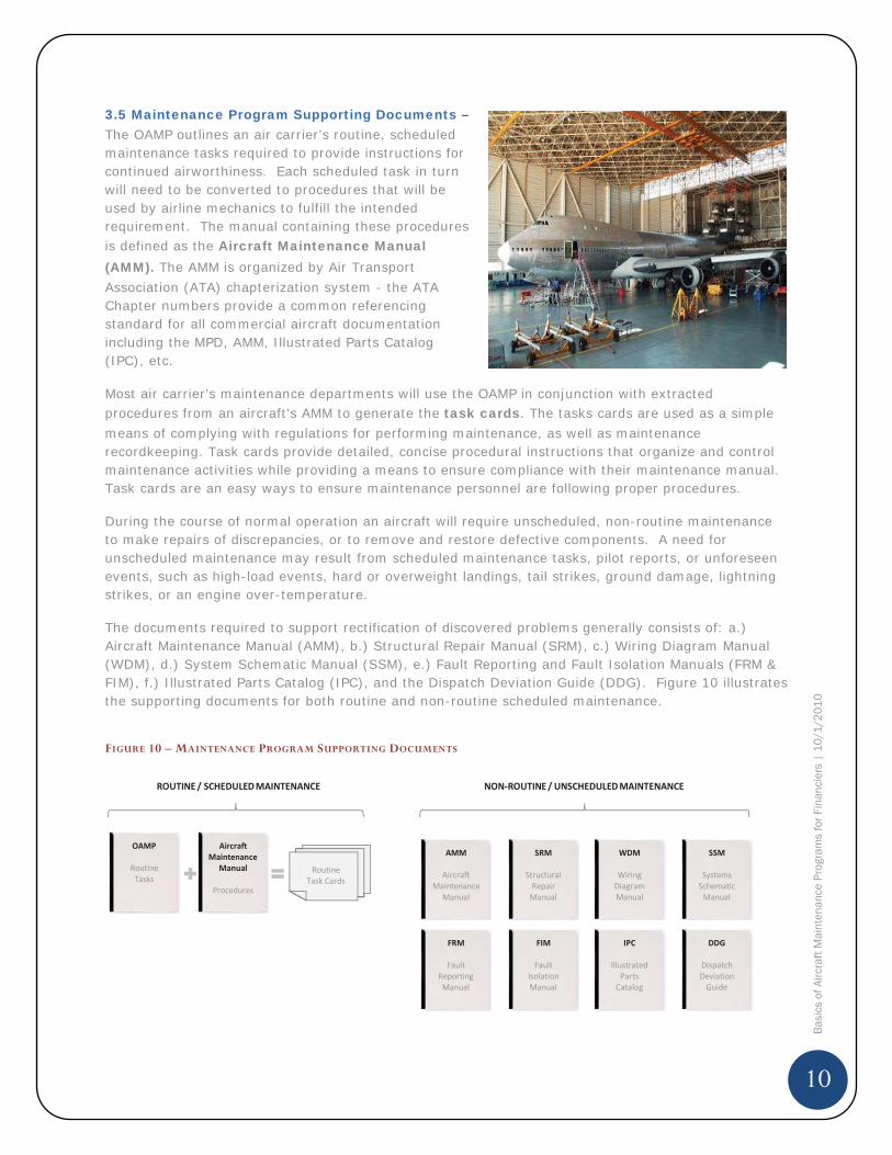
3.5 Maintenance Program Supporting Documents –The OAMP outlines an air carrier’s routine, scheduled maintenance tasks required to provide instructions for continued airworthiness. Each scheduled task in turn will need to be converted to procedures that will be used by airline mechanics to fulfill the intended requirement. The manual containing these procedures is defined as the Aircraft Maintenance Manual (AMM). The AMM is organized by Air Transport Association (ATA) chapterization system - the ATA Chapter numbers provide a common referencing standard for all commercial aircraft documentation including the MPD, AMM, Illustrated Parts Catalog (IPC), etc.
Most air carrier’s maintenance departments will use the OAMP in conjunction with extracted procedures from an aircraft’s AMM to generate the task cards. The tasks cards are used as a simple means of complying with regulations for performing maintenance, as well as maintenance recordkeeping. Task cards provide detailed, concise procedural instructions that organize and control maintenance activities while providing a means to ensure compliance with their maintenance manual. Task cards are an easy ways to ensure maintenance personnel are following proper procedures.
During the course of normal operation an aircraft will require unscheduled, non-routine maintenance to make repairs of discrepancies, or to remove and restore defective components. A need for unscheduled maintenance may result from scheduled maintenance tasks, pilot reports, or unforeseen events, such as high-load events, hard or overweight landings, tail strikes, ground damage, lightning strikes, or an engine over-temperature.
The documents required to support rectification of discovered problems generally consists of: a.) Aircraft Maintenance Manual (AMM), b.) Structural Repair Manual (SRM), c.) Wiring Diagram Manual (WDM), d.) System Schematic Manual (SSM), e.) Fault Reporting and Fault Isolation Manuals (FRM & FIM), f.) Illustrated Parts Catalog (IPC), and the Dispatch Deviation Guide (DDG). Figure 10 illustrates the supporting documents for both routine and non-routine scheduled maintenance.
FIGURE 10 – MAINTENANCE PROGRAM SUPPORTING DOCUMENTS
FRM
FaultReportingManual
FIM
FaultIsolationManual
AMM
AircraftMaintenance
Manual
SRM
StructuralRepairManual
IPC
IllustratedPartsCatalog
WDM
WiringDiagramManual
SSM
SystemsSchematicManual
DDG
DispatchDeviationGuide
OAMP
RoutineTasks
RoutineTask Cards
AircraftMaintenance
Manual
Procedures
ROUTINE / SCHEDULEDMAINTENANCE NON ROUTINE/ UNSCHEDULEDMAINTENANCE
11
Bas
ics
of A
ircra
ft M
aint
enan
ce P
rogr
ams
for F
inan
cier
s |
10
/1/2
01
0
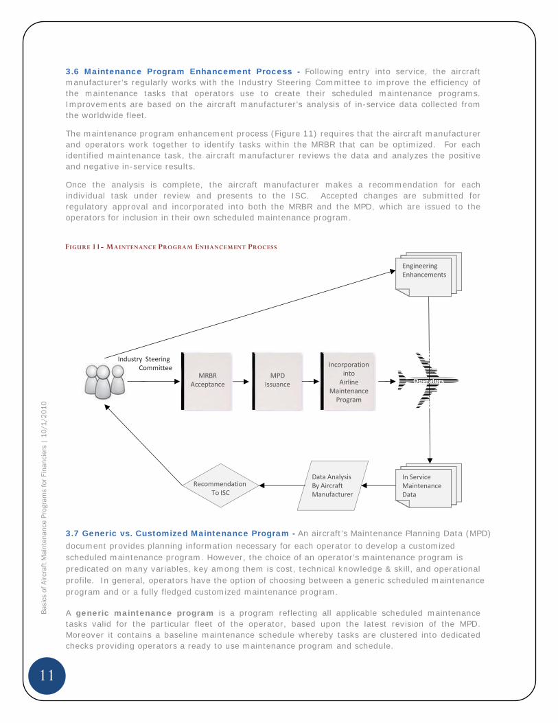
3.6 Maintenance Program Enhancement Process - Following entry into service, the aircraft manufacturer’s regularly works with the Industry Steering Committee to improve the efficiency of the maintenance tasks that operators use to create their scheduled maintenance programs. Improvements are based on the aircraft manufacturer’s analysis of in-service data collected from the worldwide fleet.
The maintenance program enhancement process (Figure 11) requires that the aircraft manufacturer and operators work together to identify tasks within the MRBR that can be optimized. For each identified maintenance task, the aircraft manufacturer reviews the data and analyzes the positive and negative in-service results.
Once the analysis is complete, the aircraft manufacturer makes a recommendation for each individual task under review and presents to the ISC. Accepted changes are submitted for regulatory approval and incorporated into both the MRBR and the MPD, which are issued to the operators for inclusion in their own scheduled maintenance program.
3.7 Generic vs. Customized Maintenance Program - An aircraft’s Maintenance Planning Data (MPD) document provides planning information necessary for each operator to develop a customized scheduled maintenance program. However, the choice of an operator’s maintenance program is predicated on many variables, key among them is cost, technical knowledge & skill, and operational profile. In general, operators have the option of choosing between a generic scheduled maintenance program and or a fully fledged customized maintenance program.
A generic maintenance program is a program reflecting all applicable scheduled maintenance tasks valid for the particular fleet of the operator, based upon the latest revision of the MPD. Moreover it contains a baseline maintenance schedule whereby tasks are clustered into dedicated checks providing operators a ready to use maintenance program and schedule.
FIGURE 11- MAINTENANCE PROGRAM ENHANCEMENT PROCESS
In ServiceMaintenanceData
Industry SteeringCommittee
MRBRAcceptance
MPDIssuance
Incorporationinto
AirlineMaintenanceProgram
Data AnalysisBy AircraftManufacturer
RecommendationTo ISC
Operators
EngineeringEnhancements
12
Bas
ics
of A
ircra
ft M
aint
enan
ce P
rogr
ams
for F
inan
cier
s |
10
/1/2
01
0
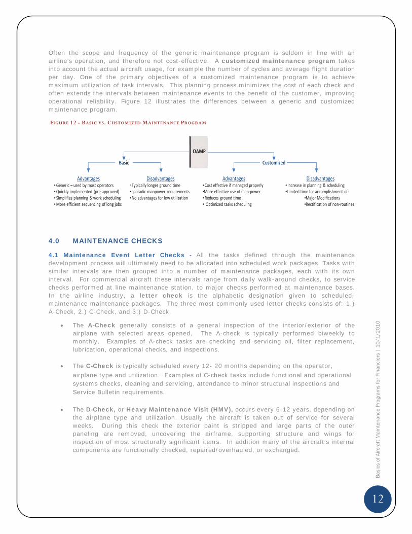
Often the scope and frequency of the generic maintenance program is seldom in line with an airline’s operation, and therefore not cost-effective. A customized maintenance program takes into account the actual aircraft usage, for example the number of cycles and average flight duration per day. One of the primary objectives of a customized maintenance program is to achieve maximum utilization of task intervals. This planning process minimizes the cost of each check and often extends the intervals between maintenance events to the benefit of the customer, improving operational reliability. Figure 12 illustrates the differences between a generic and customized maintenance program.
4.0 MAINTENANCE CHECKS
4.1 Maintenance Event Letter Checks - All the tasks defined through the maintenance development process will ultimately need to be allocated into scheduled work packages. Tasks with similar intervals are then grouped into a number of maintenance packages, each with its own interval. For commercial aircraft these intervals range from daily walk-around checks, to service checks performed at line maintenance station, to major checks performed at maintenance bases. In the airline industry, a letter check is the alphabetic designation given to scheduled-maintenance maintenance packages. The three most commonly used letter checks consists of: 1.) A-Check, 2.) C-Check, and 3.) D-Check.
The A-Check generally consists of a general inspection of the interior/exterior of the airplane with selected areas opened. The A-check is typically performed biweekly to monthly. Examples of A-check tasks are checking and servicing oil, filter replacement, lubrication, operational checks, and inspections.
The C-Check is typically scheduled every 12- 20 months depending on the operator, airplane type and utilization. Examples of C-check tasks include functional and operational systems checks, cleaning and servicing, attendance to minor structural inspections and Service Bulletin requirements.
The D-Check, or Heavy Maintenance Visit (HMV), occurs every 6-12 years, depending on the airplane type and utilization. Usually the aircraft is taken out of service for several weeks. During this check the exterior paint is stripped and large parts of the outer paneling are removed, uncovering the airframe, supporting structure and wings for inspection of most structurally significant items. In addition many of the aircraft’s internal components are functionally checked, repaired/overhauled, or exchanged.
FIGURE 12 - BASIC VS. CUSTOMIZED MAINTENANCE PROGRAM
Basic Customized
Advantages•Generic – used by most operators•Quickly implemented (pre approved)• Simplifies planning & work scheduling•More efficient sequencing of long jobs
Disadvantages• Typically longer ground time• sporadic manpower requirements•No advantages for low utilization
Advantages• Cost effective if managed properly•More effective use of man power• Reduces ground time• Optimized tasks scheduling
Disadvantages• Increase in planning & scheduling•Limited time for accomplishment of:
•Major Modifications•Rectification of non routines
OAMP
13
Bas
ics
of A
ircra
ft M
aint
enan
ce P
rogr
ams
for F
inan
cier
s |
10
/1/2
01
0
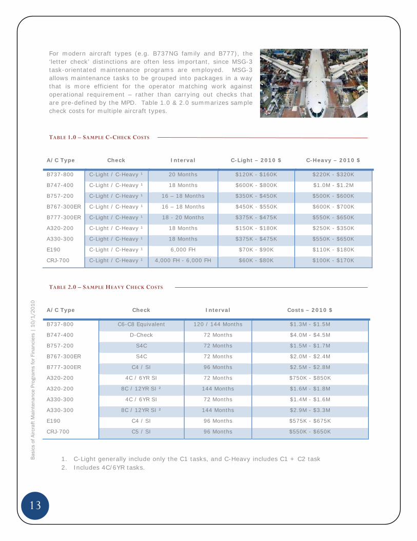
For modern aircraft types (e.g. B737NG family and B777), the ‘letter check’ distinctions are often less important, since MSG-3 task-orientated maintenance programs are employed. MSG-3 allows maintenance tasks to be grouped into packages in a way that is more efficient for the operator matching work against operational requirement – rather than carrying out checks that are pre-defined by the MPD. Table 1.0 & 2.0 summarizes sample check costs for multiple aircraft types.
TABLE 1.0 – SAMPLE C-CHECK COSTS
A/C Type Check Interval C-Light – 2010 $ C-Heavy – 2010 $
B737-800 C-Light / C-Heavy ¹ 20 Months $120K - $160K $220K - $320K
B747-400 C-Light / C-Heavy ¹ 18 Months $600K - $800K $1.0M - $1.2M
B757-200 C-Light / C-Heavy ¹ 16 – 18 Months $350K - $450K $500K - $600K
B767-300ER C-Light / C-Heavy ¹ 16 – 18 Months $450K - $550K $600K - $700K
B777-300ER C-Light / C-Heavy ¹ 18 - 20 Months $375K - $475K $550K - $650K
A320-200 C-Light / C-Heavy ¹ 18 Months $150K - $180K $250K - $350K
A330-300 C-Light / C-Heavy ¹ 18 Months $375K - $475K $550K - $650K
E190 C-Light / C-Heavy ¹ 6,000 FH $70K - $90K $110K - $180K
CRJ-700 C-Light / C-Heavy ¹ 4,000 FH - 6,000 FH $60K - $80K $100K - $170K
TABLE 2.0 – SAMPLE HEAVY CHECK COSTS
A/C Type Check Interval Costs – 2010 $
B737-800 C6-C8 Equivalent 120 / 144 Months $1.3M - $1.5M
B747-400 D-Check 72 Months $4.0M - $4.5M
B757-200 S4C 72 Months $1.5M - $1.7M
B767-300ER S4C 72 Months $2.0M - $2.4M
B777-300ER C4 / SI 96 Months $2.5M - $2.8M
A320-200 4C / 6YR SI 72 Months $750K - $850K
A320-200 8C / 12YR SI ² 144 Months $1.6M - $1.8M
A330-300 4C / 6YR SI 72 Months $1.4M - $1.6M
A330-300 8C / 12YR SI ² 144 Months $2.9M - $3.3M
E190 C4 / SI 96 Months $575K - $675K
CRJ-700 C5 / SI 96 Months $550K - $650K
1. C-Light generally include only the C1 tasks, and C-Heavy includes C1 + C2 task2. Includes 4C/6YR tasks.
14
Bas
ics
of A
ircra
ft M
aint
enan
ce P
rogr
ams
for F
inan
cier
s |
10
/1/2
01
0
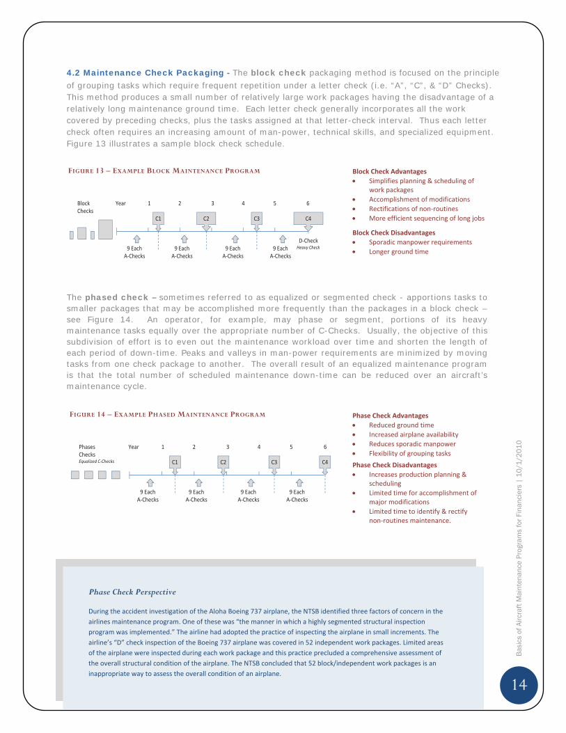
4.2 Maintenance Check Packaging - The block check packaging method is focused on the principle of grouping tasks which require frequent repetition under a letter check (i.e. “A”, “C”, & “D” Checks). This method produces a small number of relatively large work packages having the disadvantage of a relatively long maintenance ground time. Each letter check generally incorporates all the work covered by preceding checks, plus the tasks assigned at that letter-check interval. Thus each letter check often requires an increasing amount of man-power, technical skills, and specialized equipment. Figure 13 illustrates a sample block check schedule.
The phased check – sometimes referred to as equalized or segmented check - apportions tasks to smaller packages that may be accomplished more frequently than the packages in a block check – see Figure 14. An operator, for example, may phase or segment, portions of its heavy maintenance tasks equally over the appropriate number of C-Checks. Usually, the objective of this subdivision of effort is to even out the maintenance workload over time and shorten the length of each period of down-time. Peaks and valleys in man-power requirements are minimized by moving tasks from one check package to another. The overall result of an equalized maintenance program is that the total number of scheduled maintenance down-time can be reduced over an aircraft’s maintenance cycle.
FIGURE 14 – EXAMPLE PHASED MAINTENANCE PROGRAM
C1 C2 C3 C4
1 2 3 4 5 6Year
9 EachA Checks
9 EachA Checks
9 EachA Checks
9 EachA Checks
PhasesChecksEqualized C Checks
Phase Check AdvantagesReduced ground timeIncreased airplane availabilityReduces sporadic manpowerFlexibility of grouping tasks
Phase Check DisadvantagesIncreases production planning &schedulingLimited time for accomplishment ofmajor modificationsLimited time to identify & rectifynon routines maintenance.
FIGURE 13 – EXAMPLE BLOCK MAINTENANCE PROGRAM
C4C1 C2
1 2 3 4 5 6Year
9 EachA Checks
9 EachA Checks
9 EachA Checks
9 EachA Checks
D CheckHeavy Check
BlockChecks
C3
Block Check AdvantagesSimplifies planning & scheduling ofwork packagesAccomplishment of modificationsRectifications of non routinesMore efficient sequencing of long jobs
Block Check DisadvantagesSporadic manpower requirementsLonger ground time
Phase Check Perspective
During the accident investigation of the Aloha Boeing 737 airplane, the NTSB identified three factors of concern in theairlines maintenance program. One of these was “the manner in which a highly segmented structural inspectionprogram was implemented.” The airline had adopted the practice of inspecting the airplane in small increments. Theairline’s “D” check inspection of the Boeing 737 airplane was covered in 52 independent work packages. Limited areasof the airplane were inspected during each work package and this practice precluded a comprehensive assessment ofthe overall structural condition of the airplane. The NTSB concluded that 52 block/independent work packages is aninappropriate way to assess the overall condition of an airplane.
15
Bas
ics
of A
ircra
ft M
aint
enan
ce P
rogr
ams
for F
inan
cier
s |
10
/1/2
01
0
5.0 MAINTENANCE STORAGE PROGRAM
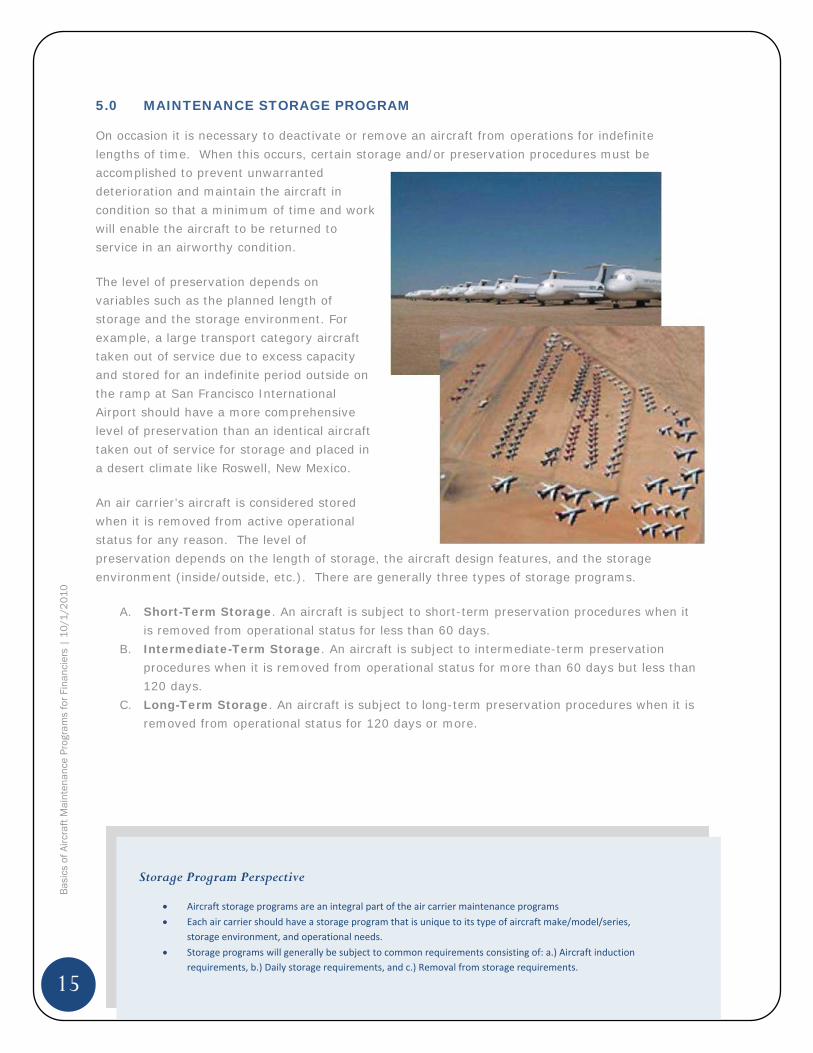
On occasion it is necessary to deactivate or remove an aircraft from operations for indefinite lengths of time. When this occurs, certain storage and/or preservation procedures must be accomplished to prevent unwarranted deterioration and maintain the aircraft in condition so that a minimum of time and work will enable the aircraft to be returned to service in an airworthy condition.
The level of preservation depends on variables such as the planned length of storage and the storage environment. For example, a large transport category aircraft taken out of service due to excess capacity and stored for an indefinite period outside on the ramp at San Francisco International Airport should have a more comprehensive level of preservation than an identical aircraft taken out of service for storage and placed in a desert climate like Roswell, New Mexico.
An air carrier’s aircraft is considered stored when it is removed from active operational status for any reason. The level of preservation depends on the length of storage, the aircraft design features, and the storage environment (inside/outside, etc.). There are generally three types of storage programs.
A. Short-Term Storage. An aircraft is subject to short-term preservation procedures when it is removed from operational status for less than 60 days.
B. Intermediate-Term Storage. An aircraft is subject to intermediate-term preservation procedures when it is removed from operational status for more than 60 days but less than 120 days.
C. Long-Term Storage. An aircraft is subject to long-term preservation procedures when it is removed from operational status for 120 days or more.
Storage Program Perspective
Aircraft storage programs are an integral part of the air carrier maintenance programsEach air carrier should have a storage program that is unique to its type of aircraft make/model/series,storage environment, and operational needs.Storage programs will generally be subject to common requirements consisting of: a.) Aircraft inductionrequirements, b.) Daily storage requirements, and c.) Removal from storage requirements.

16
Bas
ics
of A
ircra
ft M
aint
enan
ce P
rogr
ams
for F
inan
cier
s |
10
/1/2
01
0
6.0 MAINTENANCE PROGRAM BRIDGING
On occasions an operator may require changing an aircraft, or fleet of aircraft, to a new maintenance program for the purpose of increasing efficiency and reducing costs. Aircraft lessors are routinely required to transition aircraft from one maintenance program to another in order to meet specified delivery requirements.
When an aircraft transitions from one inspection program to another, the time in service, calendar times, or cycles of operation accumulated under the previous program must be applied in determining inspection due times under the new program.
Developing solutions for bridging maintenance requirements takes specialized skills and knowledge, often requiring the assistance of the aircraft manufacturer or specialist third-party maintenance repair & overhaul (MROs) companies. Bridging involves reviewing the task requirements of two maintenance programs and developing a “task differences” list. The bridging process will normally consider the following factors as a precursor to determining the appropriate task requirements:
Program differences o Systems & Powerplant program o Zonal program o Structures program
Age of the aircraft: calendar, total flight hours & flight cycles Configuration differences, Next due heavy maintenance check
o Systems/Structures C-Check o D-Check
Aircraft utilization. Operating environment. Phased and block maintenance programs. Airworthiness Directive/CMR/AL status. Service bulletin/modification incorporation. Applicable regulatory authority requirements.
Maintenance Bridging Perspective
When changing maintenance programs, an MSG 3 program often cannot migrate with the aircraft from one airline toanother. For a leasing company, a Boeing 767 aircraft coming off an MSG 3 program at airline “A” with a vast experience inoperating B767s will need to be bridged back to the manufacture’s recommended intervals before entering service withairline “B”. For example, Delta Airlines primarily uses the data collected in their continuing analysis and surveillance programto justify the time between maintenance tasks. This data is not valid for any maintenance program other than Delta Airlines.The cost, therefore, of transitioning an aircraft back to basic manufacturers’ requirements can be expensive.
17
Bas
ics
of A
ircra
ft M
aint
enan
ce P
rogr
ams
for F
inan
cier
s |
10
/1/2
01
0
7.0 MAINTENANCE PROGRAM – VALUATION PERSPECTIVE
Appraisers develop an assessment of an aircraft’s Current Market Value (CMV) assuming that the airframe, engines (modules & LLPs), landing gear, and other major maintenance events are in half-life status. To arrive at a maintenance adjusted CMV assessment, appraisers will use reported maintenance status information to compute deviations (up or down) from half-life for each major maintenance event. For example, if the aircraft has had a recent airframe heavy check, the appraisers will add value to the half-life CMV.
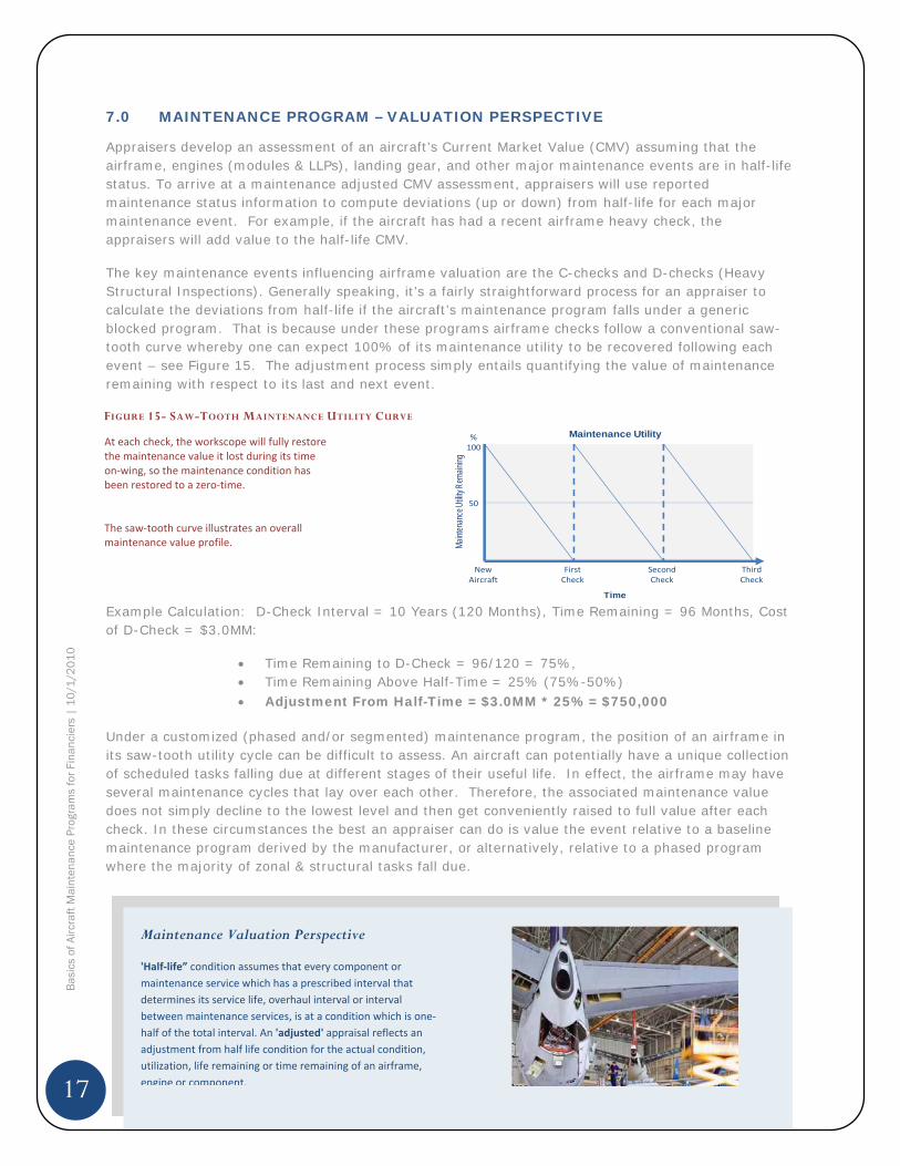
The key maintenance events influencing airframe valuation are the C-checks and D-checks (Heavy Structural Inspections). Generally speaking, it’s a fairly straightforward process for an appraiser to calculate the deviations from half-life if the aircraft’s maintenance program falls under a generic blocked program. That is because under these programs airframe checks follow a conventional saw-tooth curve whereby one can expect 100% of its maintenance utility to be recovered following each event – see Figure 15. The adjustment process simply entails quantifying the value of maintenance remaining with respect to its last and next event.
Example Calculation: D-Check Interval = 10 Years (120 Months), Time Remaining = 96 Months, Cost of D-Check = $3.0MM:
Time Remaining to D-Check = 96/120 = 75%, Time Remaining Above Half-Time = 25% (75%-50%) Adjustment From Half-Time = $3.0MM * 25% = $750,000
Under a customized (phased and/or segmented) maintenance program, the position of an airframe in its saw-tooth utility cycle can be difficult to assess. An aircraft can potentially have a unique collection of scheduled tasks falling due at different stages of their useful life. In effect, the airframe may have several maintenance cycles that lay over each other. Therefore, the associated maintenance value does not simply decline to the lowest level and then get conveniently raised to full value after each check. In these circumstances the best an appraiser can do is value the event relative to a baseline maintenance program derived by the manufacturer, or alternatively, relative to a phased program where the majority of zonal & structural tasks fall due.
Maintenance Valuation Perspective
'Half life” condition assumes that every component ormaintenance service which has a prescribed interval thatdetermines its service life, overhaul interval or intervalbetween maintenance services, is at a condition which is onehalf of the total interval. An 'adjusted' appraisal reflects anadjustment from half life condition for the actual condition,utilization, life remaining or time remaining of an airframe,engine or component.
FIGURE 15- SAW-TOOTH MAINTENANCE UTILITY CURVE
NewAircraft
FirstCheck
SecondCheck
ThirdCheck
Time
Maint
enan
ce Ut
ility R
emain
ing
50
%100
Maintenance UtilityAt each check, the workscope will fully restorethe maintenance value it lost during its timeon wing, so the maintenance condition hasbeen restored to a zero time.
The saw tooth curve illustrates an overallmaintenance value profile.
18
Bas
ics
of A
ircra
ft M
aint
enan
ce P
rogr
ams
for F
inan
cier
s |
10
/1/2
01
0
APPENDIX 1 – EXAMPLE BLOCK & PHASED MAINTENANCE PROGRAM STRUCTURE
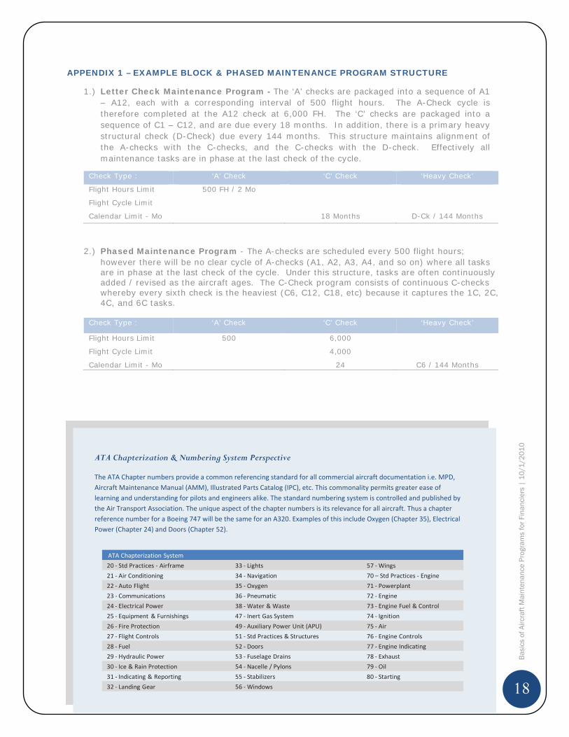
1.) Letter Check Maintenance Program - The ‘A’ checks are packaged into a sequence of A1 – A12, each with a corresponding interval of 500 flight hours. The A-Check cycle is therefore completed at the A12 check at 6,000 FH. The ‘C’ checks are packaged into a sequence of C1 – C12, and are due every 18 months. In addition, there is a primary heavy structural check (D-Check) due every 144 months. This structure maintains alignment of the A-checks with the C-checks, and the C-checks with the D-check. Effectively all maintenance tasks are in phase at the last check of the cycle.
Check Type : ‘A’ Check ‘C’ Check ‘Heavy Check’
Flight Hours Limit 500 FH / 2 Mo
Flight Cycle Limit
Calendar Limit - Mo 18 Months D-Ck / 144 Months
2.) Phased Maintenance Program - The A-checks are scheduled every 500 flight hours; however there will be no clear cycle of A-checks (A1, A2, A3, A4, and so on) where all tasks are in phase at the last check of the cycle. Under this structure, tasks are often continuously added / revised as the aircraft ages. The C-Check program consists of continuous C-checks whereby every sixth check is the heaviest (C6, C12, C18, etc) because it captures the 1C, 2C, 4C, and 6C tasks.
Check Type : ‘A’ Check ‘C’ Check ‘Heavy Check’
Flight Hours Limit 500 6,000
Flight Cycle Limit 4,000
Calendar Limit - Mo 24 C6 / 144 Months
ATA Chapterization & Numbering System Perspective
The ATA Chapter numbers provide a common referencing standard for all commercial aircraft documentation i.e. MPD,Aircraft Maintenance Manual (AMM), Illustrated Parts Catalog (IPC), etc. This commonality permits greater ease oflearning and understanding for pilots and engineers alike. The standard numbering system is controlled and published bythe Air Transport Association. The unique aspect of the chapter numbers is its relevance for all aircraft. Thus a chapterreference number for a Boeing 747 will be the same for an A320. Examples of this include Oxygen (Chapter 35), ElectricalPower (Chapter 24) and Doors (Chapter 52).
ATA Chapterization System20 Std Practices Airframe 33 Lights 57 Wings21 Air Conditioning 34 Navigation 70 – Std Practices Engine22 Auto Flight 35 Oxygen 71 Powerplant23 Communications 36 Pneumatic 72 Engine24 Electrical Power 38 Water & Waste 73 Engine Fuel & Control25 Equipment & Furnishings 47 Inert Gas System 74 Ignition26 Fire Protection 49 Auxiliary Power Unit (APU) 75 Air27 Flight Controls 51 Std Practices & Structures 76 Engine Controls28 Fuel 52 Doors 77 Engine Indicating29 Hydraulic Power 53 Fuselage Drains 78 Exhaust30 Ice & Rain Protection 54 Nacelle / Pylons 79 Oil31 Indicating & Reporting 55 Stabilizers 80 Starting32 Landing Gear 56 Windows
19
Bas
ics
of A
ircra
ft M
aint
enan
ce P
rogr
ams
for F
inan
cier
s |
10
/1/2
01
0
APPENDIX 2 – MPD TASK IDENTIFICATION
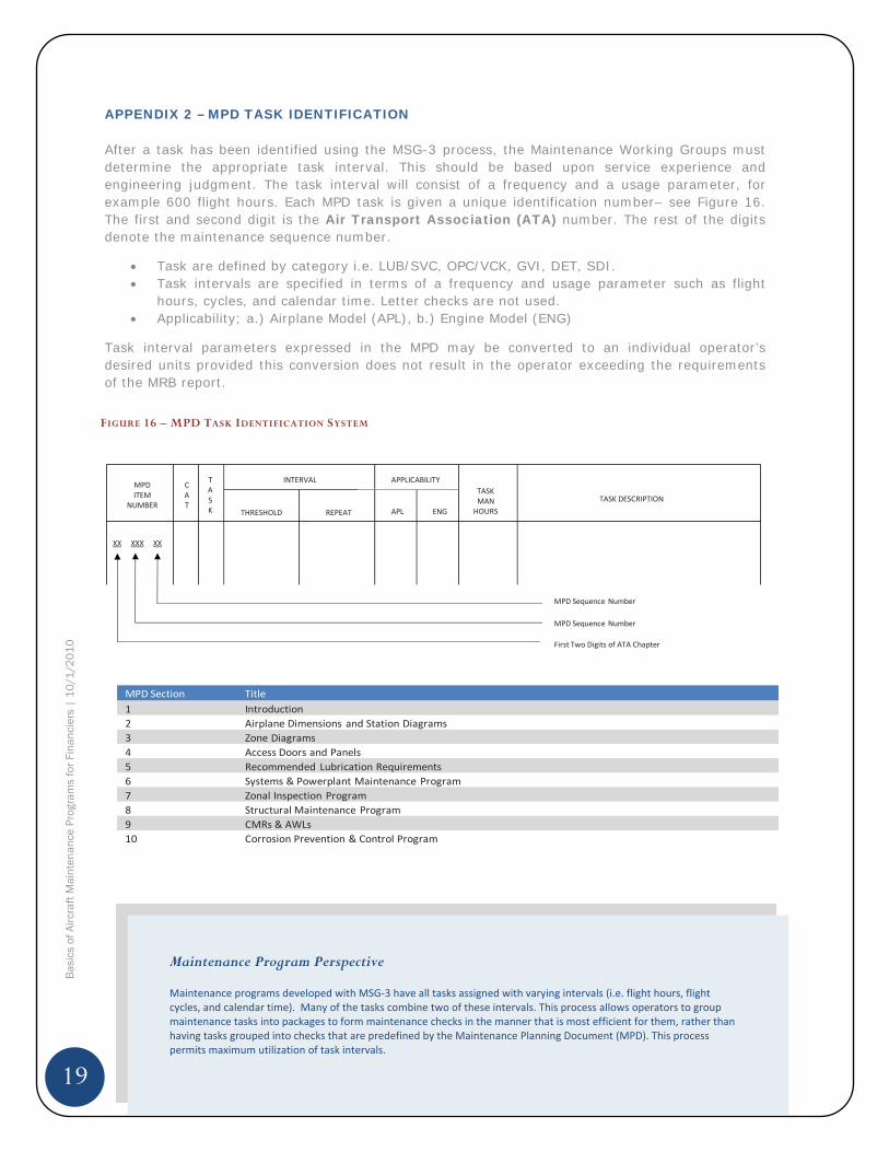
After a task has been identified using the MSG-3 process, the Maintenance Working Groups must determine the appropriate task interval. This should be based upon service experience and engineering judgment. The task interval will consist of a frequency and a usage parameter, for example 600 flight hours. Each MPD task is given a unique identification number– see Figure 16. The first and second digit is the Air Transport Association (ATA) number. The rest of the digits denote the maintenance sequence number.
Task are defined by category i.e. LUB/SVC, OPC/VCK, GVI, DET, SDI. Task intervals are specified in terms of a frequency and usage parameter such as flight hours, cycles, and calendar time. Letter checks are not used. Applicability; a.) Airplane Model (APL), b.) Engine Model (ENG)
Task interval parameters expressed in the MPD may be converted to an individual operator’s desired units provided this conversion does not result in the operator exceeding the requirements of the MRB report.
FIGURE 16 – MPD TASK IDENTIFICATION SYSTEM
MPDITEM
NUMBER
CAT
TASK
INTERVAL
THRESHOLD REPEAT
APPLICABILITY
APL ENG
TASKMANHOURS
TASK DESCRIPTION
XX XXX XX
MPD Sequence Number
MPD Sequence Number
First Two Digits of ATA Chapter
MPD Section Title1 Introduction2 Airplane Dimensions and Station Diagrams3 Zone Diagrams4 Access Doors and Panels5 Recommended Lubrication Requirements6 Systems & Powerplant Maintenance Program7 Zonal Inspection Program8 Structural Maintenance Program9 CMRs & AWLs10 Corrosion Prevention & Control Program
Maintenance Program Perspective
Maintenance programs developed with MSG 3 have all tasks assigned with varying intervals (i.e. flight hours, flightcycles, and calendar time). Many of the tasks combine two of these intervals. This process allows operators to groupmaintenance tasks into packages to form maintenance checks in the manner that is most efficient for them, rather thanhaving tasks grouped into checks that are predefined by the Maintenance Planning Document (MPD). This processpermits maximum utilization of task intervals.
20
Bas
ics
of A
ircra
ft M
aint
enan
ce P
rogr
ams
for F
inan
cier
s |
10
/1/2
01
0
APPENDIX 2 – MPD TASK IDENTIFICATION - CONTINUED
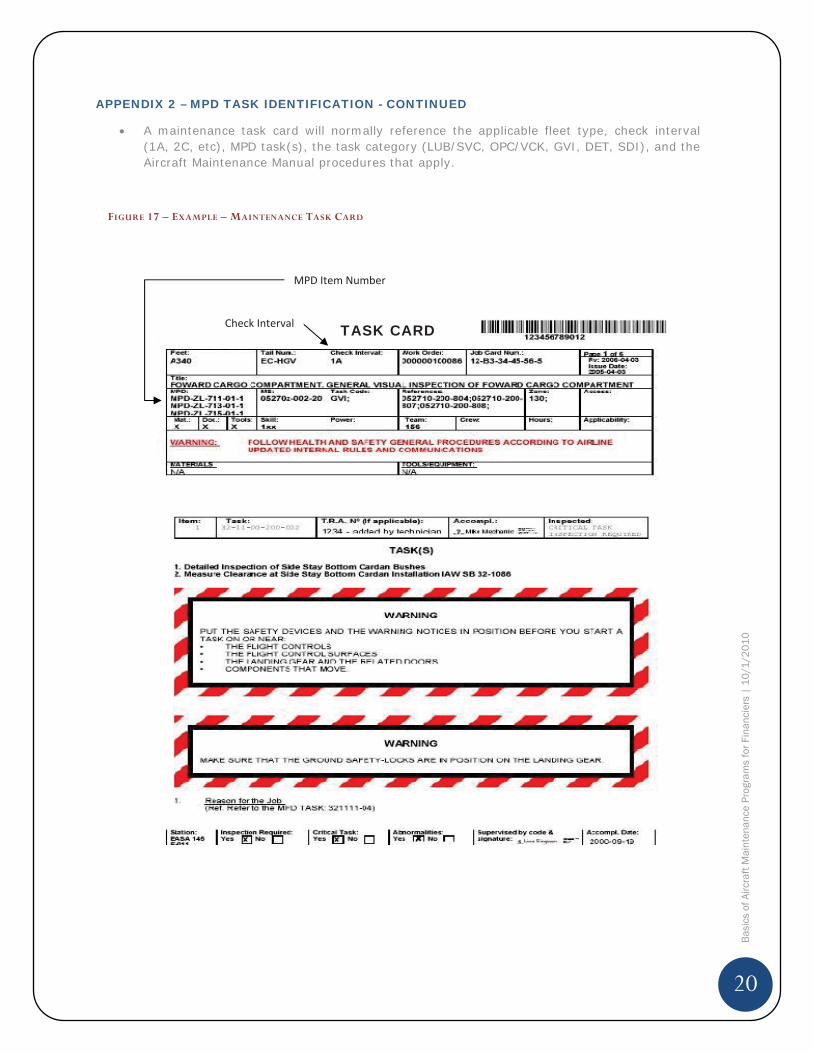
A maintenance task card will normally reference the applicable fleet type, check interval (1A, 2C, etc), MPD task(s), the task category (LUB/SVC, OPC/VCK, GVI, DET, SDI), and the Aircraft Maintenance Manual procedures that apply.
FIGURE 17 – EXAMPLE – MAINTENANCE TASK CARD
MPD Item Number
TASK CARDCheck Interval
21
Bas
ics
of A
ircra
ft M
aint
enan
ce P
rogr
ams
for F
inan
cier
s |
10
/1/2
01
0
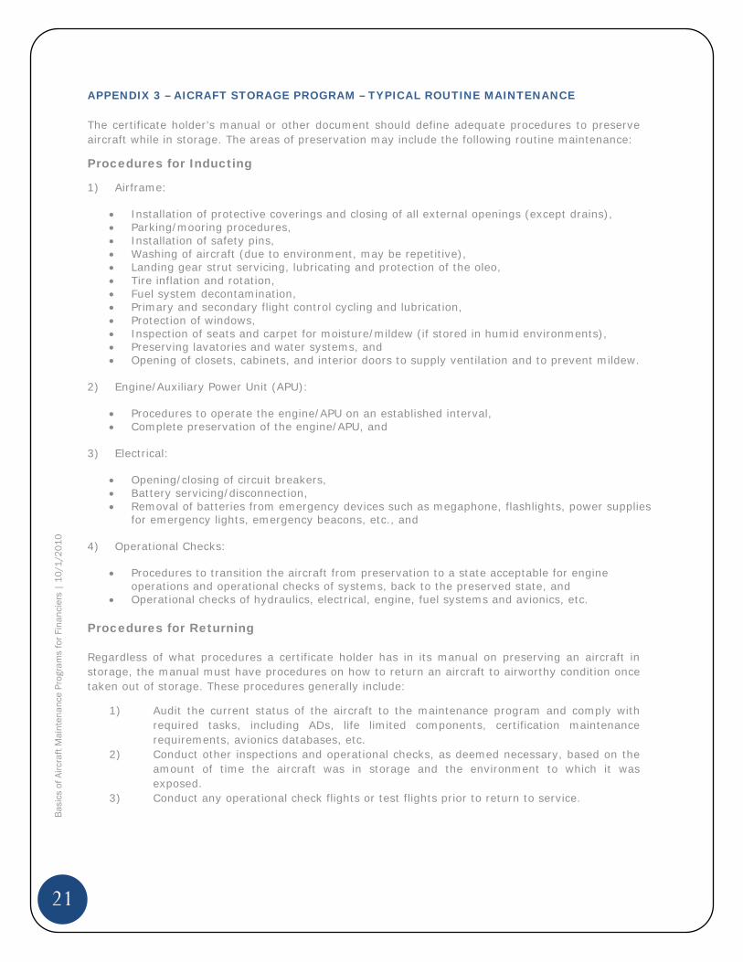
APPENDIX 3 – AICRAFT STORAGE PROGRAM – TYPICAL ROUTINE MAINTENANCE
The certificate holder’s manual or other document should define adequate procedures to preserve aircraft while in storage. The areas of preservation may include the following routine maintenance:
Procedures for Inducting
1) Airframe:
Installation of protective coverings and closing of all external openings (except drains), Parking/mooring procedures, Installation of safety pins, Washing of aircraft (due to environment, may be repetitive), Landing gear strut servicing, lubricating and protection of the oleo, Tire inflation and rotation, Fuel system decontamination, Primary and secondary flight control cycling and lubrication, Protection of windows, Inspection of seats and carpet for moisture/mildew (if stored in humid environments), Preserving lavatories and water systems, and Opening of closets, cabinets, and interior doors to supply ventilation and to prevent mildew.
2) Engine/Auxiliary Power Unit (APU):
Procedures to operate the engine/APU on an established interval, Complete preservation of the engine/APU, and
3) Electrical:
Opening/closing of circuit breakers, Battery servicing/disconnection, Removal of batteries from emergency devices such as megaphone, flashlights, power supplies for emergency lights, emergency beacons, etc., and
4) Operational Checks:
Procedures to transition the aircraft from preservation to a state acceptable for engine operations and operational checks of systems, back to the preserved state, and Operational checks of hydraulics, electrical, engine, fuel systems and avionics, etc.
Procedures for Returning
Regardless of what procedures a certificate holder has in its manual on preserving an aircraft in storage, the manual must have procedures on how to return an aircraft to airworthy condition once taken out of storage. These procedures generally include:
1) Audit the current status of the aircraft to the maintenance program and comply with required tasks, including ADs, life limited components, certification maintenance requirements, avionics databases, etc.
2) Conduct other inspections and operational checks, as deemed necessary, based on the amount of time the aircraft was in storage and the environment to which it was exposed.
3) Conduct any operational check flights or test flights prior to return to service.
22
Bas
ics
of A
ircra
ft M
aint
enan
ce P
rogr
ams
for F
inan
cier
s |
10
/1/2
01
0
REFERENCES
1. Boeing - Airline Maintenance Program Development Boeing Fleet Maintenance Seminars, Commercial Aviation Services
2. Adams, Charlotte - Aviation Maintenance Magazine Understanding MSG-3,July 2009
3. Aircraft Commerce The Relationship Between an Engine’s Value and it’s Maintenance Status, Issue 35, June/July 2004, pp 5-9
4. Beck, J & McLoughlin, B. Boeing – AeroMagazine Maintenance Program Enhancements, Qtr 04, 2006, pp 24-27
5. Gdalevitch, Manny - Aviation Maintenance Technology MSG-3, The Intelligent Maintenance, November 2009
6. Demas, C & Regis, B. Airbus FAST Magazine 38 The A380 Maintenance Program is Born, July, 2006, pp 11-19
7. U.S. Department of Transportation FAA Advisory Circular AC 120-17A Maintenance Control by Reliability Methods
8. U.S. Department of Transportation FAA Advisory Circular AC 121-22A Maintenance Review Board Procedures
9. U.S. Department of Transportation FAA Advisory Circular AC 120-16E AirCarrier Maintenance Programs
10. Air Transport Association of America – ATA MSG-3 / Operator & Manufacturer Scheduled Maintenance Development Revision 2003.1
11. Nowlan, S. & Heap, H. Reliability-Centered Maintenance, 197812. Lacey, N. & Stein, A. Airline Maintenance Programs – A Challenge for the
Appraiser / Part 1 – Trends in Airline Maintenance Practices will Require Appraisers to Alter their Methods, 2003
13. Lacey, N. & Stein, A. Airline Maintenance Programs – A Challenge for the Appraiser / Part 2 – Maintenance Programs and Aircraft Values, 2003
ACKNOWLEDGEMENTS
The author would like to thank Victor Wang, Doug Kelley and Jeff Buckio for reviewing the material, and for their guidance, recommendations, and suggestions.