Embed Size (px)
Citation preview
BASICS OF THE RENESASSYNERGY TM PLATFORMRichard Oed
2017.12
CONTENTS
1 INTRODUCTION TO THE RENESAS SYNERGY™ PLATFORM � � 03
1.1��Challenges�in�Todays�Embedded�System�Design�� ��05
1.2��Synergy�Software�Package����� �05
1.3��The�Synergy�Microcontroller�Family���� ��06
1.4��The�Synergy�Tools�and�Kits���� ��08
1.5��The�Synergy�Solutions���� ��09
1.6��The�Synergy�Gallery���� ��09
Disclaimer��� ��11
CHAPTER 1INTRODUCTION TO THE RENESAS SYNERGY™ PLATFORM
02
1 INTRODUCTION TO THE RENESAS SYNERGY™ PLATFORM
When I was asked to author a book to help engineers take their first steps with the Renesas Synergy™ Platform, I was at first
honoured and excited, but a short time later, quite daunted. Where on earth to begin? Put simply Renesas has achieved a revolutionary
new level of abstraction in the design process, enabling the designer to start development at the Application Programming Interface
(API), thus reducing time to market, lowering total cost of ownership and removing barriers to entry. Beneath that API layer sits a
massive software platform which represents more than 200 man years of development work and over a million lines of code.
And Renesas is prepared to support, warrant and maintain the complete platform as a product, to their usual high standards of
quality and reliability.
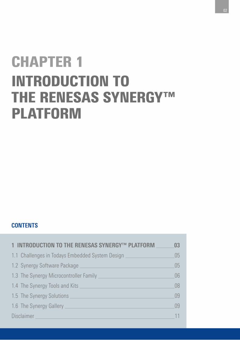
So what exactly is the Synergy Platform? Figure 1-1 shows the five main elements of the Synergy Platform:
¡ Synergy Software: A complete product-quality software platform with common APIs.
¡ Synergy Microcontrollers: A family of scalable, ARM® Cortex®-M based microcontrollers (MCUs).
¡ Synergy Gallery: Web access to Synergy specific software, tools, and more.
¡ Synergy Tools and Kits: Intuitive development tools and kits.
¡ Synergy Solutions: Specific solutions for products and applications.
Figure 1-1: The five elements of the Synergy Platform
03
What makes Synergy Platform unique is that it is supported as a product by Renesas – warranted, maintained and supported. It is also a
designer’s dream because it makes their life very easy, enabling them to develop from the API and having the benefit of a single trustworthy
point of support – Renesas. Purchasers are not forgotten either, as development can start without any up-front cost, plus the assurance of
competitive device pricing when production starts. Just to repeat – no up-front cost – you go to the Synergy Gallery, download the Synergy
Software Package (SSP) and the tool chain, and start development... ... IMMEDIATELY!
The key parts of the platform have been optimized to work together, creating new blocks where necessary but also reusing proven IP
where it is already cutting edge. For the developer this ensures that everything works together without a glitch and that software
development can start directly without having to worry about underlying layers, initialization of peripherals or setup of the Real-Time
Operating System (RTOS). This relieves developers from the burden of taking care about these basic tasks and helps reduce time to
market.
The ARM Cortex-M based MCUs have been designed with software in mind and are extremely scalable in either way – both up
and down – as registers maintain their addresses and bit-positions throughout the different series. There is a commonality of
peripheral IP across the different series. This means that a move from one series of microcontroller to another will, in most cases,
simply require a recompilation of the project with the new settings and a high-level of pin-compatibility allows for extremely easy
PCB layout.
Last, but by no means least, the Synergy Gallery on the Web provides a very convenient, single point of access to everything
needed for the development of a Synergy application: Compilers, development environments, tools, documentation and support,
not only from Renesas, but also from third-parties. So with Synergy Platform, a complete ecosystem is available at your fingertips!
Now what follows is a more engineering oriented description of the platform which is worth reading if you’re the kind of engineer
that wants to know everything. But, if on the other hand, you can not wait to start your own development at the API layer, then
feel free to skip the following chapters and go directly to either chapter 4 “Getting the Synergy Platform Toolchain Up and Running”,
which explains the installation of the toolchain, or to chapter 8 “Hello World – Hi Blinky”, which describes a first application on the
Synergy Platform.
04
Embedded systems have changed over the last decades. Prior to the turn of the century they employed few simple interfaces such as
push-buttons for input or a character LCD for output and used a single function, mostly implemented as simple loop inside main()
with interrupts to handle a limited amount of tasks. A microcontroller with a few MIPS (million instructions per second), a couple of kB
of memory and a basic serial communication would have been sufficient for this kind of system.
Today’s embedded systems however are highly connected, having a wide variety of interfaces like Ethernet, wireless, or graphical
user interfaces, all of which need to be configured / handled, and which exchange data and messages with each other and with the
outside world to form the complete application. This can require an MCU with a clock speed of 100 MHz or more, several MB of flash
memory and perhaps 128 kB of RAM. A Real-Time Operating System (RTOS) can be helpful, if not essential, as different threads need to
be prioritized and executed concurrently. Development of such systems is no longer possible in the way that legacy systems were
designed, as increased connectivity requirements make these systems less hardware and more software centric.
In addition development cycles get shorter and new feature requests come in more often. All of this not only places a high burden on
the developer who has to tackle new challenges more frequently, but is also a huge investment, not all of which may be visible right
from the beginning.
A pre-integrated platform offers a low barrier to entry and minimizes the total cost of ownership, as everything is visible upfront,
helping to speed up the development, reducing time to market and keeping the projects budget on track. All this allows more features
to be integrated in the available time and at the same cost and therefore to create heavily differentiated products.
It is also worth mentioning that Synergy Platform requires no upfront expenditure. Purchase just one Synergy MCU and you can
access commercial software with a value of several hundred K$, with no limit on development seats, number of end-products, or
number of total MCUs.
1.2 Synergy Software Package
At the heart of the complete Synergy Platform ecosystem is the Synergy Software Package (SSP), specifically optimized for the Synergy
MCU architecture. It integrates Application Frameworks for system level services, Functional Libraries containing specialized software,
for example for digital signal processing, very efficient Hardware Abstraction Layer (HAL) drivers for all peripherals, and the Board
Support Package (BSP) including start-up code for boards and MCUs.
In addition to the software mentioned above the SSP also includes renowned and proven packages from Express Logic such as
the ThreadX® RTOS and the X-Ware™ communication stacks and graphics middleware. The SSP covers all basic functionalities like
initialization of the microcontroller and its peripherals, or the setup of the RTOS. Many engineers spend months, if not years,
developing this kind of low-level software rather than being able to focus their time on differentiating in the application – this is
the power of Synergy Platform!
If you are curious about the details of the SSP please be patient. We will cover them in chapters 2 and 3.
1.1 Challenges in Todays Embedded System Design
05
1.3 The Synergy Microcontroller Family
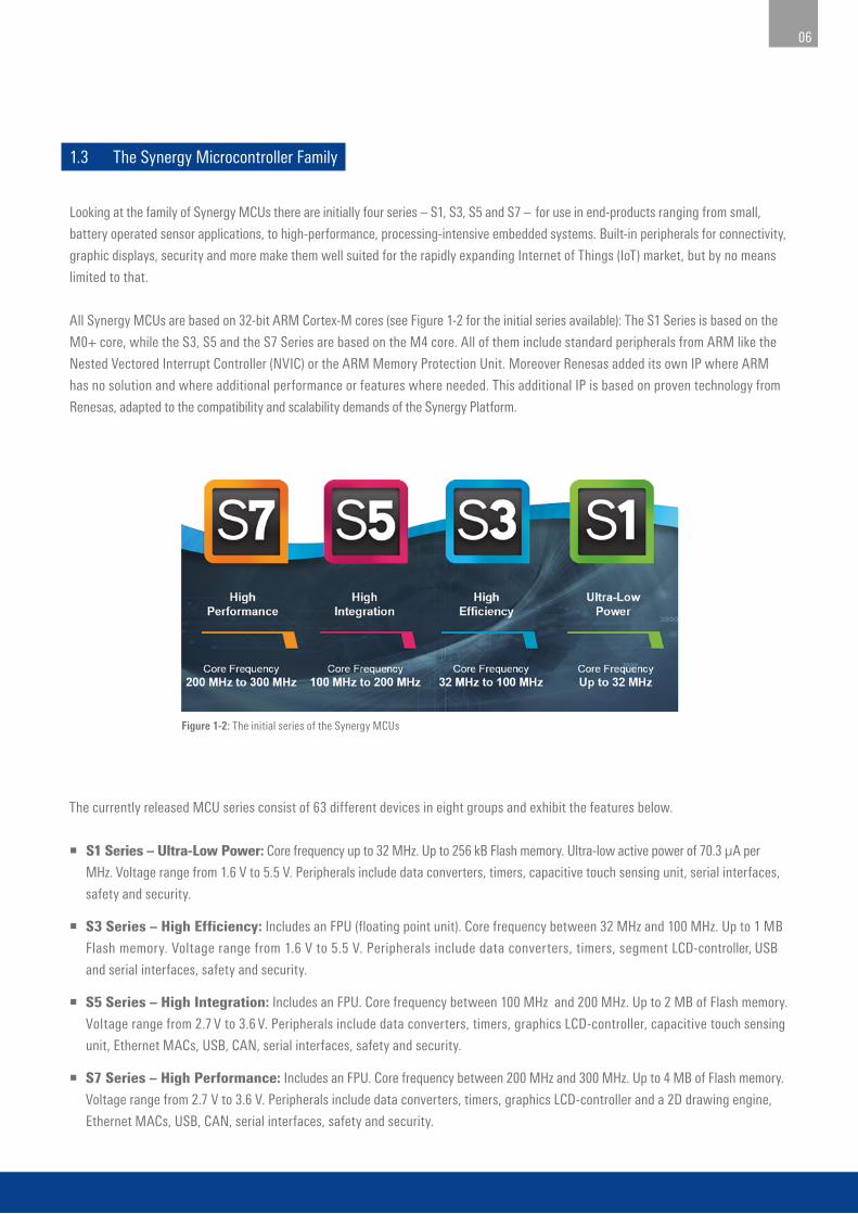
Looking at the family of Synergy MCUs there are initially four series – S1, S3, S5 and S7 – for use in end-products ranging from small,
battery operated sensor applications, to high-performance, processing-intensive embedded systems. Built-in peripherals for connectivity,
graphic displays, security and more make them well suited for the rapidly expanding Internet of Things (IoT) market, but by no means
limited to that.
All Synergy MCUs are based on 32-bit ARM Cortex-M cores (see Figure 1-2 for the initial series available): The S1 Series is based on the
M0+ core, while the S3, S5 and the S7 Series are based on the M4 core. All of them include standard peripherals from ARM like the
Nested Vectored Interrupt Controller (NVIC) or the ARM Memory Protection Unit. Moreover Renesas added its own IP where ARM
has no solution and where additional performance or features where needed. This additional IP is based on proven technology from
Renesas, adapted to the compatibility and scalability demands of the Synergy Platform.
The currently released MCU series consist of 63 different devices in eight groups and exhibit the features below.
¡ S1 Series – Ultra-Low Power: Core frequency up to 32 MHz. Up to 256 kB Flash memory. Ultra-low active power of 70.3 µA per
MHz. Voltage range from 1.6 V to 5.5 V. Peripherals include data converters, timers, capacitive touch sensing unit, serial interfaces,
safety and security.
¡ S3 Series – High Efficiency: Includes an FPU (floating point unit). Core frequency between 32 MHz and 100 MHz. Up to 1 MB
Flash memory. Voltage range from 1.6 V to 5.5 V. Peripherals include data converters, timers, segment LCD-controller, USB
and serial interfaces, safety and security.
¡ S5 Series – High Integration: Includes an FPU. Core frequency between 100 MHz and 200 MHz. Up to 2 MB of Flash memory.
Voltage range from 2.7 V to 3.6 V. Peripherals include data converters, timers, graphics LCD-controller, capacitive touch sensing
unit, Ethernet MACs, USB, CAN, serial interfaces, safety and security.
¡ S7 Series – High Performance: Includes an FPU. Core frequency between 200 MHz and 300 MHz. Up to 4 MB of Flash memory.
Voltage range from 2.7 V to 3.6 V. Peripherals include data converters, timers, graphics LCD-controller and a 2D drawing engine,
Ethernet MACs, USB, CAN, serial interfaces, safety and security.
Figure 1-2: The initial series of the Synergy MCUs
06
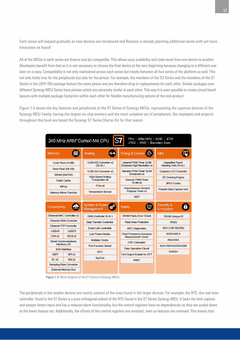
Figure 1-3: Block diagram of the S7 Series of Synergy MCUs
Each series will expand gradually as new devices are introduced and Renesas is already planning additional series with yet more
innovation on board!
All of the MCUs in each series are feature and pin compatible. This allows easy scalability and code reuse from one device to another.
Developers benefit from that as it is not necessary to choose the final device at the very beginning because changing to a different one
later on is easy. Compatibility is not only maintained across each series but mostly between all four series of the platform as well. This
not only holds true for the peripherals but also for the pinout. For example, the members of the S3 Series and the members of the S7
Series in the LQFP-100 package feature the same pinout and are therefore drop-in replacements for each other. Similar packages over
different Synergy MCU Series have pinouts which are extremely similar to each other. This way it is even possible to create circuit board
layouts with multiple package footprints within each other for flexible manufacturing options of the end-product.
Figure 1-3 shows the key features and peripherals of the S7 Series of Synergy MCUs, representing the superset devices of the
Synergy MCU Family, having the largest on-chip memory and the most complete set of peripherals. Our examples and projects
throughout this book are based the Synergy S7 Series Starter Kit for that reason.
The peripherals in the smaller devices are mostly subsets of the ones found in the larger devices. For example, the RTC, the real-time
controller, found in the S1 Series is a pure orthogonal subset of the RTC found in the S7 Series Synergy MCU. It lacks the time capture
and tamper detect input and has a reduced alarm functionality, but the control registers have no dependencies as they are scaled down
to the lower feature set. Additionally, the offsets of the control registers are constant, even as features are removed. This means that
07
software written for the RTC of a S1 Series device will work on a S7 Series device without modification. Scaling down from a S7 to a
S1 Series device just means that only those lines of code need to be changed which belong to a feature not available on the smaller
device, making the life of developers a lot easier. This clearly shows that there was a lot of thought put into the silicon.
1.4 The Synergy Tools and Kits
Renesas has taken great steps to create useful software and hardware development tools that can be used to explore the platform’s
technical capabilities and that will take the user beyond the evaluation stage, all the way to production.
The available software development tools include the following:
¡ e2 studio: The Eclipse-based Integrated Solution Development Environment (ISDE) from Renesas including special configurators for the
Synergy Platform. Uses the GCC ARM® Embedded code generation tools.
¡ IAR Embedded Workbench® for Renesas Synergy™: The Integrated Development Environment from IAR Systems® for the
Synergy Platform, using IAR’s proprietary ARM® Cortex®-M C-compiler. Works with the Renesas Synergy™ Standalone Configurator (SSC).
¡ TraceX®: The RTOS event and behaviour visualizer and analysis tool from Express Logic.
¡ GUIX Studio™: A PC based program from Express Logic for designing graphical user interfaces.
e2 studio contains all the tools necessary to create, compile and debug projects for the Synergy Platform. It is called ISDE as
additional solution-oriented components and plug-ins have been added, making it more powerful. This is especially true for the
configurators, which allow an easy graphical access to the different hardware features like the clock module or the pin configuration
without the need for deep study of the user’s guide. These configurators will create all the necessary settings and the initialization
code automatically and include an error checking feature to detect problematic settings already at design time.
During development, hardware will be needed to run first tests. In most cases, this will be necessary well before the user’s own
board is ready. For that purpose, Synergy Platform offers four different types of kits, and all come with an on-board J-Link® debugging
and programming interface:
¡ Synergy Starter Kits (SK): For general evaluation. Uses an S7G2 Group Microcontroller (MCU), as this is the superset device,
giving a good introduction to the Synergy Platform. You can evaluate the complete ecosystem with this kit and later on pick any
device from the different families for your own project, as everything is also applicable to the smaller siblings. About 80% of the pins
of the MCU are accessible through connectors, so attaching your own hardware is not a problem, an important capability
feature for evaluation.
¡ Synergy Development Kits (DK): For full project prototyping with access to all pins through many expansion ports and up to
four Pmod™ connectors. They feature a Bluetooth® low energy radio for wireless connection to a mobile device and many other
specialized expansion boards.
¡ Synergy Promotion Kits (PK): For demonstration of the main features of the Synergy Platform. These boards are initial evaluation
platforms that can be used to determine which kit is appropriate for further development of a product and provide easy-to-access
interfaces to the peripherals of the Synergy microcontrollers.
¡ Synergy Target Board Kits (TB): Provide an inexpensive entry point to evaluation, prototyping and developing for the Synergy family
of microcontrollers. The boards come with pin headers that allow access to the MCU signals, as well as several on-board peripherals.
08
1.5 The Synergy Solutions
For special needs, like human-machine interfaces (HMI), a smart sensor network or industrial networking, the Synergy Solutions
provide specialized kits, which go beyond the typical embedded product development hardware. There are two different flavours of
them:
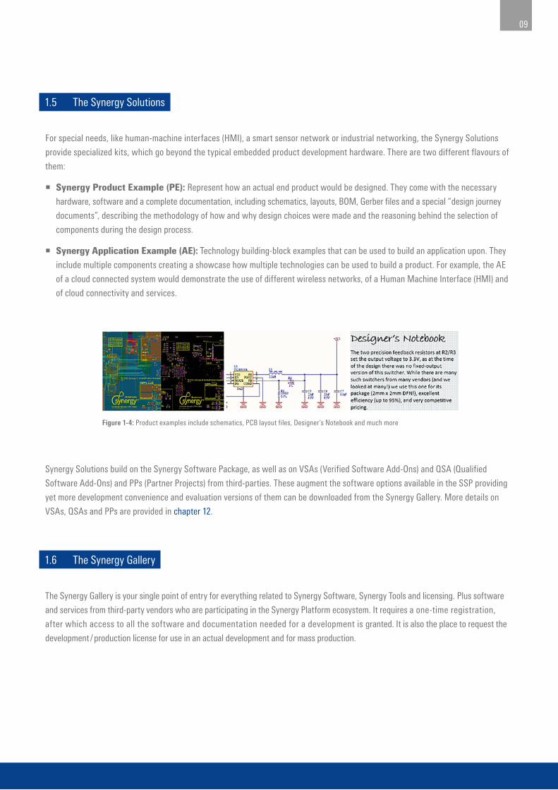
¡ Synergy Product Example (PE): Represent how an actual end product would be designed. They come with the necessary
hardware, software and a complete documentation, including schematics, layouts, BOM, Gerber files and a special “design journey
documents”, describing the methodology of how and why design choices were made and the reasoning behind the selection of
components during the design process.
¡ Synergy Application Example (AE): Technology building-block examples that can be used to build an application upon. They
include multiple components creating a showcase how multiple technologies can be used to build a product. For example, the AE
of a cloud connected system would demonstrate the use of different wireless networks, of a Human Machine Interface (HMI) and
of cloud connectivity and services.
Synergy Solutions build on the Synergy Software Package, as well as on VSAs (Verified Software Add-Ons) and QSA (Qualified
Software Add-Ons) and PPs (Partner Projects) from third-parties. These augment the software options available in the SSP providing
yet more development convenience and evaluation versions of them can be downloaded from the Synergy Gallery. More details on
VSAs, QSAs and PPs are provided in chapter 12.
1.6 The Synergy Gallery
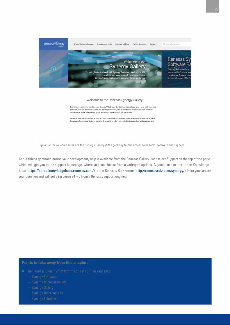
The Synergy Gallery is your single point of entry for everything related to Synergy Software, Synergy Tools and licensing. Plus software
and services from third-party vendors who are participating in the Synergy Platform ecosystem. It requires a one-time registration,
after which access to all the software and documentation needed for a development is granted. It is also the place to request the
development / production license for use in an actual development and for mass production.
Figure 1-4: Product examples include schematics, PCB layout files, Designer’s Notebook and much more
09
Points to take away from this chapter:
¡ The Renesas Synergy™ Platform consists of five elements: – Synergy Software
– Synergy Microcontrollers
– Synergy Gallery
– Synergy Tools and Kits
– Synergy Solutions
And if things go wrong during your development, help is available from the Renesas Gallery. Just select Support on the top of the page
which will get you to the support homepage, where you can choose from a variety of options. A good place to start it the Knowledge
Base (https://en-eu.knowledgebase.renesas.com/) or the Renesas Rulz Forum (http://renesasrulz.com/synergy/). Here you can ask
your question and will get a response 24 – 5 from a Renesas support engineer.
Figure 1-5: The welcome screen of the Synergy Gallery is the gateway for the access to all tools, software and support
10
11
Copyright: © 2017 Renesas Electronics Europe GmbH
Disclaimer:
This volume is provided for informational purposes without any warranty for correctness and completeness. The contents are not intended to be
referred to as a design reference guide and no liability shall be accepted for any consequences arising from the use of this book.