Embed Size (px)
Citation preview
ProductProductProductProduct DataDataDataDataJanuaryJanuaryJanuaryJanuary 2007200720072007
Hardware ManualHardware ManualHardware ManualHardware Manual
MESANORMESANORMESANORMESANOR
BME BME BME BME xxxx Basic Motion ElementBasic Motion ElementBasic Motion ElementBasic Motion Element
BDE BDE BDE BDE xxxx Basic Drive ElementBasic Drive ElementBasic Drive ElementBasic Drive Element
BME V1.4e2
RECEIVING AND HANDLING
Upon delivery of the equipment, inspect the shipping containers and contents for indications of damages incurried in transit. If any of the items specified in the bill of lading are damaged, or the quantity is incorrect, donot accept them until the freight or express agent makes an appropriate notation on your freight bill orexpress receipt.
Claims for loss or damage in shipment must not be deducted from your invoice, nor should payment bewithheld pending adjustment of any such claims.
Store the equipment in a clean , dry area. It is advisable to leave the equipment in its shipping container untilready fore use. Each amplifier is checked carefully before shipment. However, upon receipt, the user shouldmake sure that the amplifier corresponds to or is properly rated in terms of rated voltage and current for thetype of motor which is to be driven. The descriptive label affixed to the amplifier specifies electrical ratings.
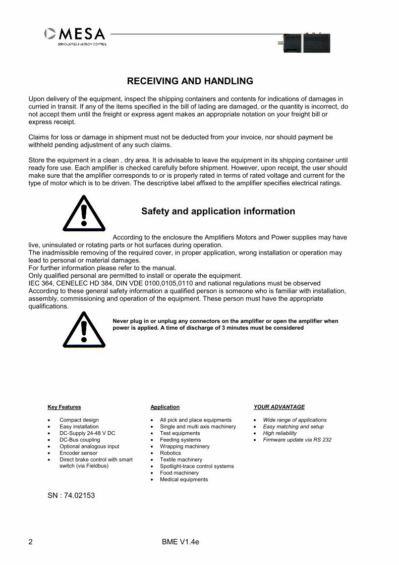
Safety and application information
According to the enclosure the Amplifiers Motors and Power supplies may havelive, uninsulated or rotating parts or hot surfaces during operation.The inadmissible removing of the required cover, in proper application, wrong installation or operation maylead to personal or material damages.For further information please refer to the manual.Only qualified personal are permitted to install or operate the equipment.IEC 364, CENELEC HD 384, DIN VDE 0100,0105,0110 and national regulations must be observedAccording to these general safety information a qualified person is someone who is familiar with installation,assembly, commissioning and operation of the equipment. These person must have the appropriatequalifications.
Never plug in or unplug any connectors on the amplifier or open the amplifier whenpower is applied. A time of discharge of 3 minutes must be considered
Key Features Application YOUR ADVANTAGE
• Compact design• Easy installation• DC-Supply 24-48 V DC• DC-Bus coupling• Optional analogous input• Encoder sensor• Direct brake control with smart
switch (via Fieldbus)
• All pick and place equipments• Single and multi axis machinery• Test equipments• Feeding systems• Wrapping machinery• Robotics• Textile machinery• Spotlight-trace control systems• Food machinery• Medical equipments
• Wide range of applications• Easy matching and setup• High reliability• Firmware update via RS 232
SN : 74.02153

BME V1.4e 3
Contents1 BASIS MODELS BME / BDE – POWER RANGE..................................................................................5
2 GENERAL .....................................................................................................................................................6
3 TECHNICAL SPECIFICATIONS BME ....................................................................................................7
3.1 MECHANICAL AND MOTOR DATA ................................................................................................................73.2 POWER STAGE..............................................................................................................................................8
4 PRINCIPLE OF OPERATION AND BASIC FUNCTIONS...................................................................10
4.1 BLOCK DIAGRAM .......................................................................................................................................104.2 INPUTS AND OUTPUTS................................................................................................................................114.3 STATE MACHINE........................................................................................................................................114.4 PARAMETERS.............................................................................................................................................114.5 FUNCTIONS AND OPERATION MODES.........................................................................................................114.6 ENCODER...................................................................................................................................................124.7 SPEED ADJUSTMENT ..................................................................................................................................124.8 HARDWARE LIMIT SWITCH ........................................................................................................................124.9 FAST STOP .................................................................................................................................................134.10 ENABLE .................................................................................................................................................134.11 DRIVE READY........................................................................................................................................134.12 OPERATING MODE.................................................................................................................................134.13 TEMPERATURE SENSORS .......................................................................................................................134.14 SOFTWARE RESET..................................................................................................................................134.15 POWER ON-RESET.................................................................................................................................134.16 DEMAND SET VALUE –TORQUE –SPEED-POSITION ...............................................................................134.17 REFERENCE INPUT.................................................................................................................................13
5 CONTROLLER SET-UP............................................................................................................................14
5.1 BASIC SET-UP - FIRST STEPS.......................................................................................................................14
6 POWER SUPPLY .......................................................................................................................................15
6.1 WIRING RECOMMENDATIONS ....................................................................................................................156.2 +24 V DC ELECTRONIC SUPPLY VOLTAGE................................................................................................156.3 MOTOR BRAKE CONTROL (OPTION) ..........................................................................................................156.4 FUSE ..........................................................................................................................................................15
7 DEFAULT SETTINGS ...............................................................................................................................16
8 COMMISSIONING-TERMINAL DESCRIPTION.................................................................................17
8.1 LED DISPLAY............................................................................................................................................188.2 TERMINAL DESCRIPTION BME...................................................................................................................188.3 POWER SUPPLY X1 ....................................................................................................................................188.4 EXTERNAL FUSE ........................................................................................................................................188.5 CONTROL SIGNALS X2...............................................................................................................................198.6 PROFIBUS X3 .........................................................................................................................................208.7 CAN-BUS X3 ............................................................................................................................................208.8 PRINCIPLE CONNECTORS SHIELD CONNECTION .........................................................................................218.9 D-SUB-PINNING.........................................................................................................................................218.10 RS232 CONNECTOR ..............................................................................................................................228.11 CONSTRUCTION .....................................................................................................................................228.12 NON-MODEM CABLE (TYPICAL).............................................................................................................228.13 BME TEST CIRCUIT PROFIBUS .............................................................................................................238.14 BME TEST CIRCUIT CAN BUS.............................................................................................................24
9 EARTHING AND INSTALLATION ACCORDING TO EMC NORMS..............................................25

BME V1.4e4
9.1 GENERAL INDICATIONS..............................................................................................................................259.2 GENERAL RULES........................................................................................................................................259.3 CONTROL CABINET....................................................................................................................................259.4 HOUSING....................................................................................................................................................259.5 POWER CABLE ...........................................................................................................................................269.6 ESTIMATION OF NEEDED WIRE RANGE .......................................................................................................269.7 PRINCIPLE WIRING DIAGRAM.....................................................................................................................289.8 CONTROL CABLES......................................................................................................................................299.9 BME/BDE CAN BUS WIRING ..................................................................................................................29
9.9.1 General.............................................................................................................................................299.9.2 Standard Version ..............................................................................................................................299.9.3 Simplified Version ............................................................................................................................30
9.10 BME/BDE PROFIBUS WIRING...........................................................................................................31
10 KNOWN PROBLEMS AND LIMITATIONS..........................................................................................32
11 FAULT FINDING- QUICK REFERENCE ..............................................................................................33
11.1 HARDWARE AND SOFTWARE ERRORS....................................................................................................34
12 ADDITIONAL INFORMATION ..............................................................................................................35
13 BDE - BASIC DRIVE ELEMENT............................................................................................................36
13.1 MOTOR TEMPERATURE PROBE ..............................................................................................................3713.2 MOTOR CONNECTIONS ..........................................................................................................................37
13.2.1 DC Motor Servo with brushes......................................................................................................3713.2.2 Motor Feedback X4 .....................................................................................................................3713.2.3 Motor Power X5...........................................................................................................................37
13.3 BRUSHLESS SERVO MOTOR...................................................................................................................3813.3.1 Motor Feedback X4 .....................................................................................................................3813.3.2 Motor Power X5...........................................................................................................................3813.3.3 Minimal Motor Inductance ..........................................................................................................38
13.4 MECHANICS...........................................................................................................................................3913.5 OPTIONAL CONNECTOR SETS ................................................................................................................3913.6 ENCODER ..............................................................................................................................................4013.7 HALL DEVICE ........................................................................................................................................4013.8 MOTOR BRAKE CONTROL......................................................................................................................40

BME V1.4e 5
1 Basis Models BME / BDE – Power range
Family name Overview
B-Basic PROFIBUS- or CAN-Bus interface or analog inputM-Motion RS 232E-Element High dynamic, high bandwidth
High efficiency power stage
Fast current controllerFull protection modeLimit switch and stop inputMotor brake control with smart switch
Type Imax(A)
IN(A)
Vrated(V DC)
Vmin(V DC)
Vmax(V DC)
Pmax (W)(48/60V)
Internal CapacitorDC Power supply
BME 0505 10 5 48 10 60 480 820 µFBME 0510 20 10 48 10 60 960 1640 µFBME 0605 10 5 65 10 80 600 470µFBME 0610 20 10 65 10 80 1200 940 µF
Other voltage and current ratings on requestType label indication
BME 0505 P xxxMESANOR Option / Motortype
Basic Motion Element Fieldbus (P/C)PROFIBUS (P)
CANopen (C)DC Bus Voltage 48 V (05) DC rated current in A (05)
Other power range and options on special request.
Type Imax(A)
IN(A)
Vrated(V DC)
Vmin(V DC)
Vmax(V DC)
Pmax (W)(48/60V)
Internal CapacitorDC Power supply
BDE 0505 10 5 48 10 60 480 820 µFBDE 0510 20 10 48 10 60 600 1640 µFBDE 0605 10 5 65 10 80 960 470µFBDE 0610 20 10 65 10 80 1200 940 µF
Lmin –BDE in Chapter BDE
BME V1.4e6
2 General
The BME is an integrated electronic motor with fieldbus interface for a wide range ofapplications. The BME includes the advantage of intelligent servo drive and a de centralcompact actuator. The principle allows a dramatic reduction of wiring and a high flexibility ofapplication. The BDE is a Servo drive which allows you to use motors dislocated from theelectronic.
The following operation modes are available :
• Torque mode
This mode allows a high dynamic and precise torque control between +/- maximum Torque.
• Speed mode
This mode allows a high dynamic and precise speed control between +/- maximum Speed.
• Profile Position Mode
This mode allows a high dynamic and precise position control until the +/- maximum positionvalue.
• Interpolated Position Mode
This mode is only available in CAN-version
• Sequence Position Mode32 position sequences are available including homing / reference.
• Stand alone Speed or Torque mode
This mode allows the speed or torque control via analog input
• RS 232 Mode
The RS 232 is a diagnose interface to set-up, adjust and test the BME/BDE. The built in helpfunctions like RS 232 control panel, digital scope and other features allow a fast set-up and ashort completion times for a wide range of applications.

BME V1.4e 7
3 Technical Specifications BME
3.1 Mechanical and Motor Data
Basic Motor 071 072 073 074
Flange size mm 70 70 70 70Max. torque Nm 0,88 2,0 2,5 3Rated torque Nm 0,44 1,0 1,2 1,5Max. speed (48VDC) rpm 3000 3000 3000 3000
Length A – without brake mm 170 190 210 230Length A – with brake mm 200 220 240 260Weight without brake g 1600 2000 2400 2900Weight with brake g 1900 2300 2700 3500
Winding insulation Class F Class F Class F Class FRadial load Fr N 216 245 275 314Axial load Fa N 98 98 98 98
Cooling with aluminium plate mm 300 x 300 300 x 300 400 x 400 400 x 40010 mm thick upright positionMotor brake (24 V DC) optional optional optional optional
BME V1.4e8
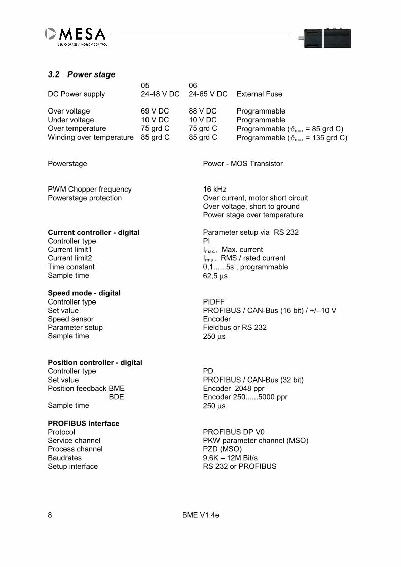
3.2 Power stage05 06
DC Power supply 24-48 V DC 24-65 V DC External Fuse
Over voltage 69 V DC 88 V DC ProgrammableUnder voltage 10 V DC 10 V DC ProgrammableOver temperature 75 grd C 75 grd C Programmable (ϑmax = 85 grd C)Winding over temperature 85 grd C 85 grd C Programmable (ϑmax = 135 grd C)
Powerstage Power - MOS Transistor
PWM Chopper frequency 16 kHzPowerstage protection Over current, motor short circuit
Over voltage, short to groundPower stage over temperature
Current controller - digital Parameter setup via RS 232Controller type PICurrent limit1 Imax., Max. currentCurrent limit2 Irms , RMS / rated currentTime constant 0,1......5s ; programmableSample time 62,5 µs
Speed mode - digitalController type PIDFFSet value PROFIBUS / CAN-Bus (16 bit) / +/- 10 VSpeed sensor EncoderParameter setup Fieldbus or RS 232Sample time 250 µs
Position controller - digitalController type PDSet value PROFIBUS / CAN-Bus (32 bit)Position feedback BME Encoder 2048 ppr BDE Encoder 250......5000 pprSample time 250 µs
PROFIBUS InterfaceProtocol PROFIBUS DP V0Service channel PKW parameter channel (MSO)Process channel PZD (MSO)Baudrates 9,6K – 12M Bit/sSetup interface RS 232 or PROFIBUS
BME V1.4e 9
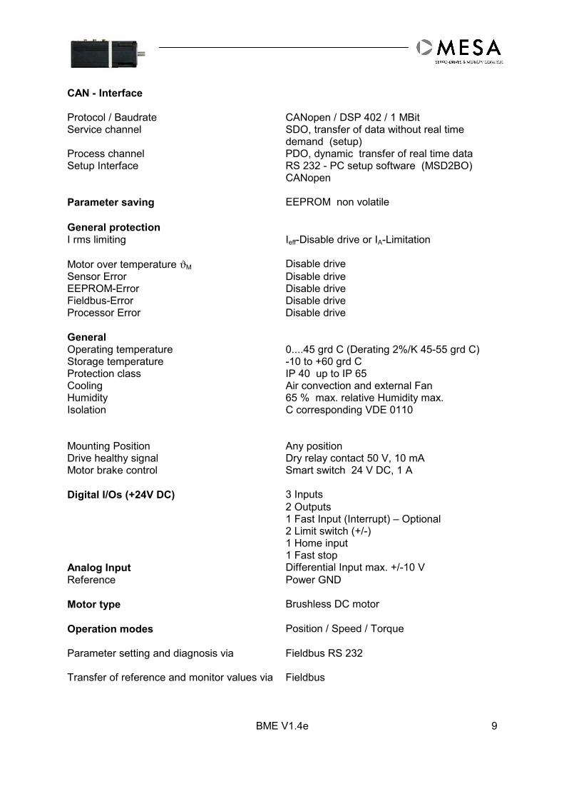
CAN - Interface
Protocol / Baudrate CANopen / DSP 402 / 1 MBitService channel SDO, transfer of data without real time
demand (setup)Process channel PDO, dynamic transfer of real time dataSetup Interface RS 232 - PC setup software (MSD2BO)
CANopen
Parameter saving EEPROM non volatile
General protectionI rms limiting Ieff-Disable drive or IA-Limitation
Motor over temperature ϑM Disable driveSensor Error Disable driveEEPROM-Error Disable driveFieldbus-Error Disable driveProcessor Error Disable drive
GeneralOperating temperature 0....45 grd C (Derating 2%/K 45-55 grd C)Storage temperature -10 to +60 grd CProtection class IP 40 up to IP 65Cooling Air convection and external FanHumidity 65 % max. relative Humidity max.Isolation C corresponding VDE 0110
Mounting Position Any positionDrive healthy signal Dry relay contact 50 V, 10 mAMotor brake control Smart switch 24 V DC, 1 A
Digital I/Os (+24V DC) 3 Inputs2 Outputs1 Fast Input (Interrupt) – Optional2 Limit switch (+/-)1 Home input1 Fast stop
Analog Input Differential Input max. +/-10 VReference Power GND
Motor type Brushless DC motor
Operation modes Position / Speed / Torque
Parameter setting and diagnosis via Fieldbus RS 232
Transfer of reference and monitor values via Fieldbus
10
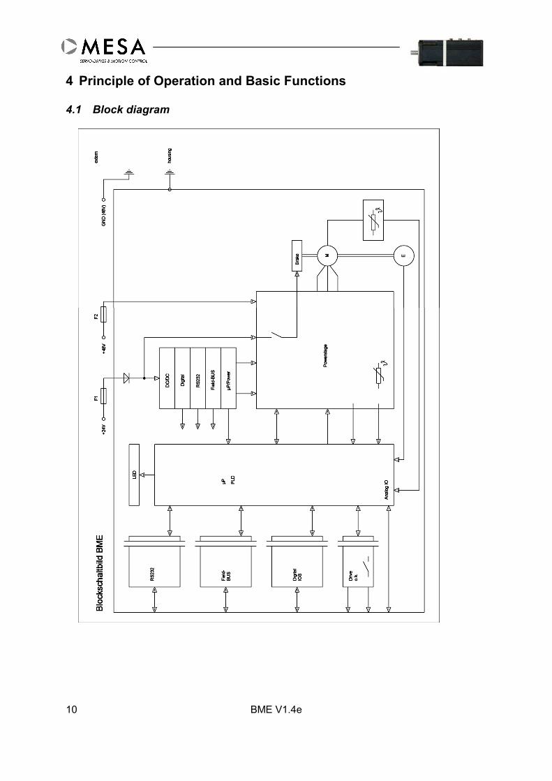
4 Principle of Operation and Basic Functions
4.1 Block diagram
BME V1.4e

BME V1.4e 11
4.2 Inputs and OutputsThe BME/BDE has a number of digital inputs and outputs which are used to fulfil the desiredfunctionality of the machine. There are 2 categories of inputs and outputs: „dedicated type“with fix functions like limit switch, reference, stop and „general type“ which can user defined .
4.3 State MachineWhen the drive is powered on it goes in a defined state. Every further event is switching thestate machine in a well defined manner into the corresponding state.
For the detailed description of the state machine see device control section of thecorresponding fieldbus communication profile manual.The basic operations of the drive described in this manual are realised in the „OperationEnabled“ and „Switched On“ states. The transfer between these 2 states are realised by the„Enable“/ „Disable“ operations.
4.4 ParametersThe BME/BDE parameters are stored in the non-volatile memory (EEPROM). In the start-upphase the parameters are loaded from the EEPROM into the RAM memory and activated.Now the parameter in the RAM memory can be changed by the communication interfaces inthe defined conditions (drive enable/disable, parameter type read/write or read only) andthey are automatically activated. The new parameters have to be saved into the EEPROMbefore power off (auxiliary supply), otherwise they are lost.
4.5 Functions and Operation ModesThe functionality of the BME/BDE can be achieved using the desired operation modes. Thechanging of the operation mode can be made generally in every operation mode except„Operation Enabled“ mode.In order to change the operation mode, the following operations are to be realised:• Disable the drive (get out from „Operation Enabled“ mode);• Change into the desired operation mode and check if the operation mode has changed;• Enable the drive (put into „Operation Enabled“ mode).
The following operation modes are available :• Speed drive via the communication interfaces;The drive is working in speed mode and actual speed is following the reference speedtransmitted by the communication interface.
Start conditions Start StopSpeed reference operationmodeDrive disabled
Set speed reference to zeroEnable driveSet reference speed via thecommunication interface
Set speed reference to zeroDisable drive
• Jogging operation via the communication interfaces

BME V1.4e12
The drive is moving with the programmed jogging speed in the specified direction. Aftersetting the jogging speed the operation can be started as below:
Start conditions Start StopDrive enabledProfile position operationmode
Set start bit in the ControlWord depending on thedesired direction
Reset start bit in the ControlWord
• Profile position operation mode via the communication interfaces
Start conditions Start StopDrive enabledProfile position operationmodeSequence selected
Toggle start bit in the ControlWord
The move stops automaticallywhen it is finished.
• Homing mode via the communication interfaces
Start conditions Start StopDrive enabledProfile position operationmodeSequence selected
Set start bit in the ControlWordReset the start bit after thehoming is started
The homing procedure stopsautomatically when theprogrammed function isfinished
4.6 EncoderThe resolution of the build in encoder (BME) is 2048 ppr. An external encoder must have aresolution between 250....5000 ppr.
4.7 Speed AdjustmentThe motor speed can be adjusted by software via communication interface. The actualspeed is measured by the encoder.
4.8 Hardware Limit SwitchConnecting of +24 V DC to the terminals for negative and positive direction deactivate therelated limit switch and will enable the corresponding direction. If the limit switch is active thecorresponding direction will be disabled. The status is indicated in the MSD2BO.
The drive can be moved out in the opposite direction. If the drive was in a homing procedurethan it stops with a procedure error.If the switch is deactivated the drives behaviour is depending on the actual operation mode:-Speed mode: the drive restarts the move with the same speed.-Profile position mode: the started move can be continued by a new start sequencecommand.-Homing mode: after reset the procedure error is, the homing procedure can be restarted.
BME V1.4e 13
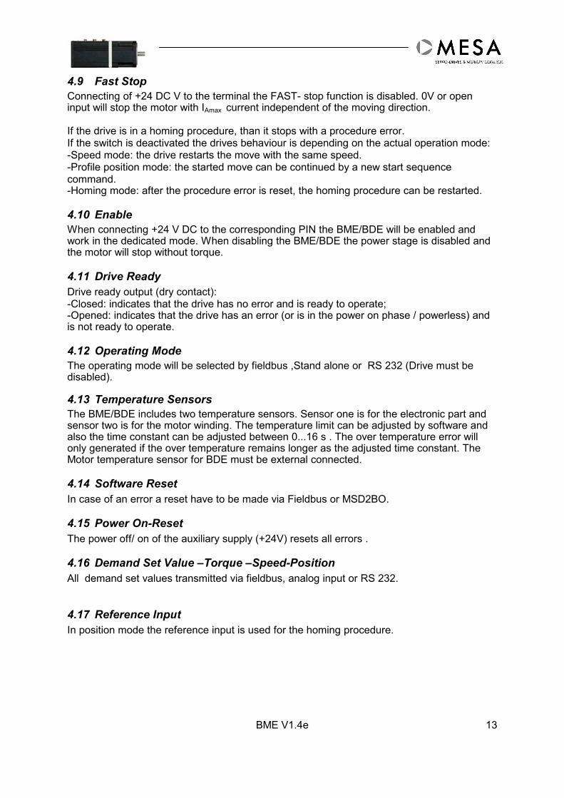
4.9 Fast StopConnecting of +24 DC V to the terminal the FAST- stop function is disabled. 0V or openinput will stop the motor with IAmax current independent of the moving direction.
If the drive is in a homing procedure, than it stops with a procedure error.If the switch is deactivated the drives behaviour is depending on the actual operation mode:-Speed mode: the drive restarts the move with the same speed.-Profile position mode: the started move can be continued by a new start sequencecommand.-Homing mode: after the procedure error is reset, the homing procedure can be restarted.
4.10 EnableWhen connecting +24 V DC to the corresponding PIN the BME/BDE will be enabled andwork in the dedicated mode. When disabling the BME/BDE the power stage is disabled andthe motor will stop without torque.
4.11 Drive ReadyDrive ready output (dry contact):-Closed: indicates that the drive has no error and is ready to operate;-Opened: indicates that the drive has an error (or is in the power on phase / powerless) andis not ready to operate.
4.12 Operating ModeThe operating mode will be selected by fieldbus ,Stand alone or RS 232 (Drive must bedisabled).
4.13 Temperature SensorsThe BME/BDE includes two temperature sensors. Sensor one is for the electronic part andsensor two is for the motor winding. The temperature limit can be adjusted by software andalso the time constant can be adjusted between 0...16 s . The over temperature error willonly generated if the over temperature remains longer as the adjusted time constant. TheMotor temperature sensor for BDE must be external connected.
4.14 Software ResetIn case of an error a reset have to be made via Fieldbus or MSD2BO.
4.15 Power On-ResetThe power off/ on of the auxiliary supply (+24V) resets all errors .
4.16 Demand Set Value –Torque –Speed-PositionAll demand set values transmitted via fieldbus, analog input or RS 232.
4.17 Reference InputIn position mode the reference input is used for the homing procedure.

BME V1.4e14
5 Controller Set-upThe setup can be made by software via RS 232, please use the actual version of theMSD2BO Software. The MSD2BO Software manual will provide you with all necessaryinformation for set-up and tuning.
The BME/BDE is always starting in the last saved operation mode. In order to have a quickand simple start of the BME/BDE with the needed functionality, it is recommended to savethe appropriate operation mode, before disconnecting the BME/BDE.During the first communication the MSD2BO will automatically store a parameter file in the“device” directory.
Attention !
The RS 232 interface is only for set-up and diagnoses purpose. Parameter changes willhave direct influence to the process. Wrong parameters can cause unintentional behaviouror damage.When capturing software control with the MSD2BO software the control by the fieldbus isstopped immediately – any running operation is interrupted!
5.1 Basic Set-up - first steps
Wire up the BME/BDE according to the test circuitDisable the drive (hardware)Install the MSD2BO program on your PCConnect the RS 232 on the PC and BME/BDEConnect the BME/BDE with the 24 V DC Auxiliaiy supply (+24V)Connect the 24 - 48 V DC power supplyWait until the LED 2 will light greenStart the MSD2BO - Program
The BME/BME is in fieldbus mode. To change parameters or use the RS 232 control panelyou should take over the software control (“Capture software control”).
In the start-up phase of the BME/BDE the following operation are executed:• DSP initialisation;• Loading the drive parameters from the non-volatile memory (EEPROM);• Initialising of the control loops;• Initialising and activating of the communication interfaces (Fieldbus and RS 232);• Checking of the drive status and input signals;• Setting of the outputs, monitor signals and LED’s;• Setting the state machine into initial state;
BME V1.4e 15
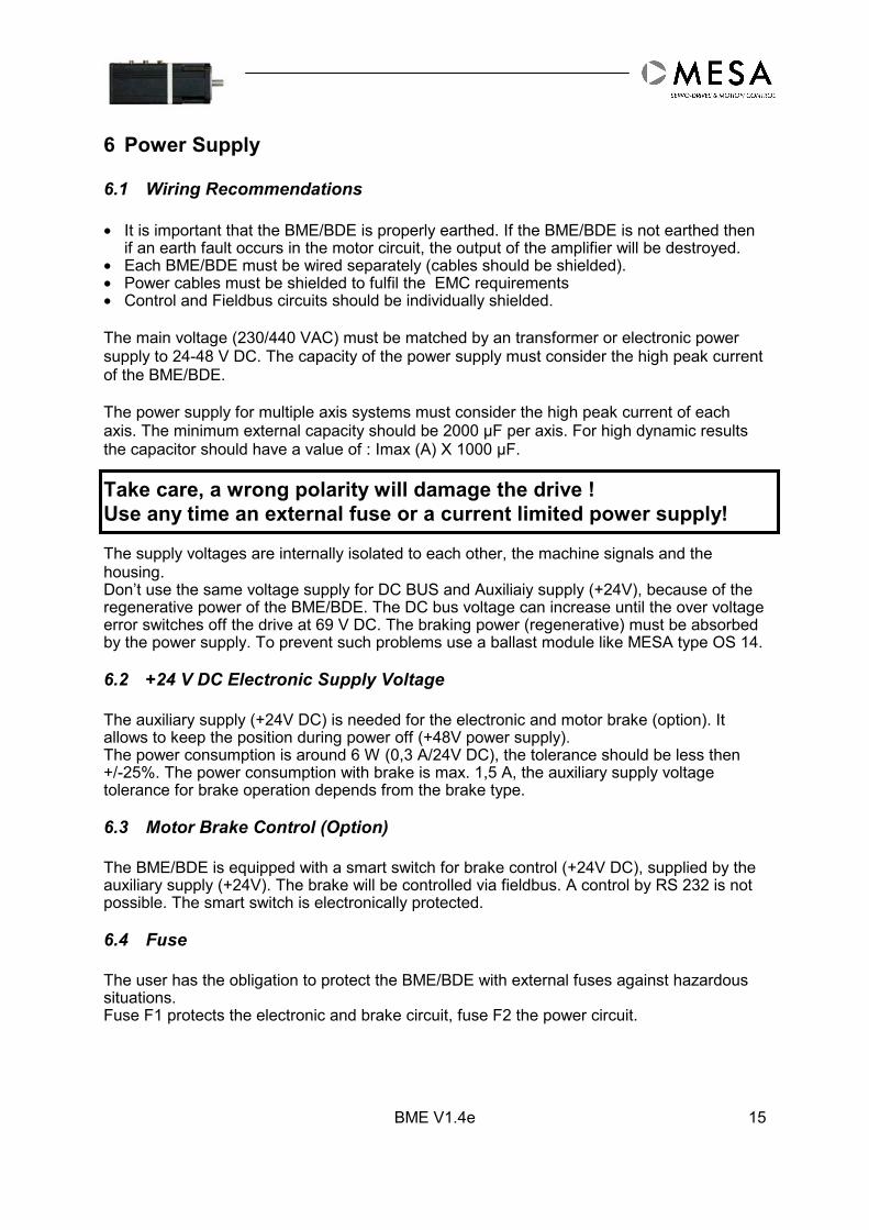
6 Power Supply
6.1 Wiring Recommendations
• It is important that the BME/BDE is properly earthed. If the BME/BDE is not earthed thenif an earth fault occurs in the motor circuit, the output of the amplifier will be destroyed.
• Each BME/BDE must be wired separately (cables should be shielded).• Power cables must be shielded to fulfil the EMC requirements• Control and Fieldbus circuits should be individually shielded.
The main voltage (230/440 VAC) must be matched by an transformer or electronic powersupply to 24-48 V DC. The capacity of the power supply must consider the high peak currentof the BME/BDE.
The power supply for multiple axis systems must consider the high peak current of eachaxis. The minimum external capacity should be 2000 µF per axis. For high dynamic resultsthe capacitor should have a value of : Imax (A) X 1000 µF.
Take care, a wrong polarity will damage the drive !Use any time an external fuse or a current limited power supply!
The supply voltages are internally isolated to each other, the machine signals and thehousing.Don’t use the same voltage supply for DC BUS and Auxiliaiy supply (+24V), because of theregenerative power of the BME/BDE. The DC bus voltage can increase until the over voltageerror switches off the drive at 69 V DC. The braking power (regenerative) must be absorbedby the power supply. To prevent such problems use a ballast module like MESA type OS 14.
6.2 +24 V DC Electronic Supply Voltage
The auxiliary supply (+24V DC) is needed for the electronic and motor brake (option). Itallows to keep the position during power off (+48V power supply).The power consumption is around 6 W (0,3 A/24V DC), the tolerance should be less then+/-25%. The power consumption with brake is max. 1,5 A, the auxiliary supply voltagetolerance for brake operation depends from the brake type.
6.3 Motor Brake Control (Option)
The BME/BDE is equipped with a smart switch for brake control (+24V DC), supplied by theauxiliary supply (+24V). The brake will be controlled via fieldbus. A control by RS 232 is notpossible. The smart switch is electronically protected.
6.4 Fuse
The user has the obligation to protect the BME/BDE with external fuses against hazardoussituations.Fuse F1 protects the electronic and brake circuit, fuse F2 the power circuit.

BME V1.4e16
7 Default SettingsThe following table shows the default setting . For special applications / modifications thesettings are different. For more information pls. ask the service department.
Name Function Default RemarkCommunication
RS 232 PC communication Baud rate 19200 automatic
Power stage
DC Power supply Limit of Power Voltage Max. 69 V DC Lower values possibleMin. 9 V DC Higher values possible
Motor temperature Motor protection 95 grd C Lower values possibleMotor sensor type Motor protection NTC PTC – not usedDrive temperature Electronic protection 75 grd C Lower values possibleDrive sensor type Electronic protection NTC PTC – not used
Operating modeMode Controller mode Speed Torque/Position
Current loopCurrent controller P-Gain 4500 Optimised
I-Gain 500 OptimisedImax Max. Output current 100 % =Imax 20-100%(Imax)Irms Rated current 50 % =Imax 20-50% (Imax)Irms-Limitation Irms-protection mode Limitation fusing
Speed loopMode Controller mode PIDFF-Mode P-ModeP P-Gain 15000I I-Gain 100D D-Gain 0FF Feed-Forward-Gain 0Max. Speed Limitation of max. Speed 14.000 rpm 500-14.000 rpmSensor resolution Resolution of Pos. Sensor 2048 ppr BDE variable
BME FixPosition loop
Controller mode PFFP P-Gain 125FF Feed-Forward-Gain 0
PROFIBUS –Interface
MESA BME GSD Load file from CDPROFIBUSAddress
125
CAN-Bus-InterfaceBus speed Baud rate 1 MBd 0,8 MBdCAN-Cycle Cycle time 2 ms 1-20 ms
only valid after Power off/onAttention! Never change without further Information’s Attention!

BME V1.4e 17
8 Commissioning-Terminal Description
Attention!
Before applying any voltage, make sure that the BME/BDE(housing) is straight and correctly connected to ground / earth :
CHECK BEFORE POWER ON !
• Earthing according to the norm• Supply voltage• Wiring• Special adjustments• Rated and max. current for the application• All external switches in right position• Whether the BME is mechanically fixed, motor shaft is free and not yet connected with the
machine! If this is not possible, maximal current must be reduced to 25 %.• Then the BME is disabled by the enable input.
Make sure enable BME/BDE after power on !
Never plug in or unplug any connectors on the BME/BDE or open it whenpower is applied. The time of discharge of 3 minutes must be considered !
BME V1.4e18
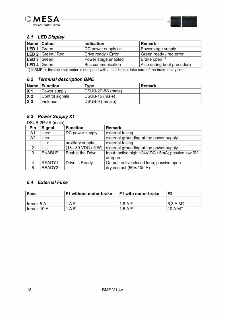
8.1 LED DisplayName Colour Indication RemarkLED 1 Green DC power supply ok Powerstage supplyLED 2 Green / Red Drive ready / Error Green ready / red errorLED 3 Green Power stage enabled Brake open 1)
LED 4 Green Bus communication Also during boot procedure1) If BME or the external motor is equipped with a stall brake, take care of the brake delay time
8.2 Terminal description BMEName Function Type RemarkX 1 Power supply DSUB-2P-5S (male)X 2 Control signals DSUB-15 (male)X 3 Fieldbus DSUB-9 (female)
8.3 Power Supply X1DSUB-2P-5S (male)
Pin Signal Function RemarkA1 Ucc+ external fusingA2 Ucc-
DC power supplyexternal grounding at the power supply
1 UH+ external fusing2 UH-
auxiliary supply(18...30 VDC / 6 W) external grounding at the power supply
3 ENABLE Enable the Drive Input; active high +24V DC / 5mA; passive low 0Vor open
4 READY1 Drive is Ready Output; active closed loop; passive open5 READY2 dry contact (50V/10mA)
8.4 External Fuse
Fuse F1 without motor brake F1 with motor brake F2
Irms = 5 A 1 A F 1,6 A F 6,3 A MTIrms = 10 A 1 A F 1,6 A F 10 A MT
BME V1.4e 19
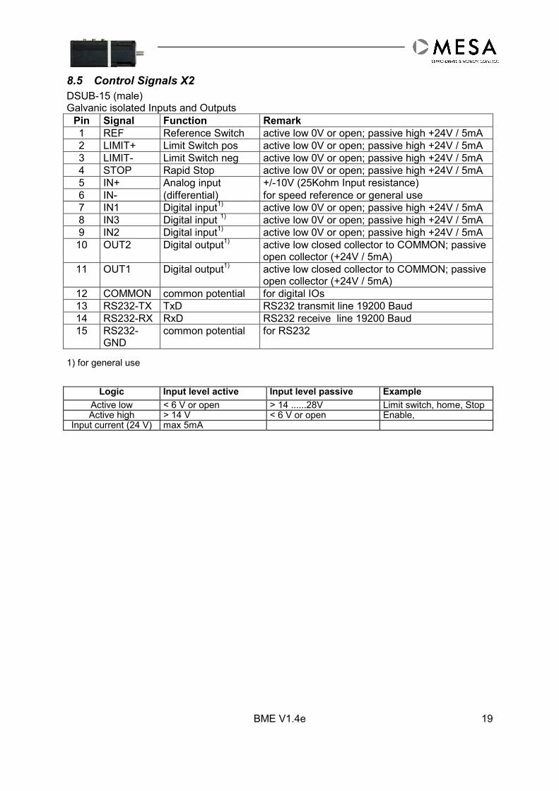
8.5 Control Signals X2DSUB-15 (male)Galvanic isolated Inputs and Outputs
Pin Signal Function Remark1 REF Reference Switch active low 0V or open; passive high +24V / 5mA2 LIMIT+ Limit Switch pos active low 0V or open; passive high +24V / 5mA3 LIMIT- Limit Switch neg active low 0V or open; passive high +24V / 5mA4 STOP Rapid Stop active low 0V or open; passive high +24V / 5mA5 IN+ Analog input +/-10V (25Kohm Input resistance)6 IN- (differential) for speed reference or general use7 IN1 Digital input1) active low 0V or open; passive high +24V / 5mA8 IN3 Digital input 1) active low 0V or open; passive high +24V / 5mA9 IN2 Digital input1) active low 0V or open; passive high +24V / 5mA10 OUT2 Digital output1) active low closed collector to COMMON; passive
open collector (+24V / 5mA)11 OUT1 Digital output1) active low closed collector to COMMON; passive
open collector (+24V / 5mA)12 COMMON common potential for digital IOs13 RS232-TX TxD RS232 transmit line 19200 Baud14 RS232-RX RxD RS232 receive line 19200 Baud15 RS232-
GNDcommon potential for RS232
1) for general use
Logic Input level active Input level passive ExampleActive low < 6 V or open > 14 ......28V Limit switch, home, StopActive high > 14 V < 6 V or open Enable,
Input current (24 V) max 5mA

BME V1.4e20
8.6 PROFIBUS X3DSUB-9 (female)
PIN Name Description Remark1 Shield2 -
RxD/TxD-P Receive / Transmit data –plus, B-line (red)4 RTS direction control signal5 DGND Data ground (reference potential to VP)6 VP Power supply plus, (P5V)7 -8 RxD/TxD-N Receive / Transmit data –N, A-line (green)9 -
8.7 CAN-Bus X3DSUB-9 (male)
Pin Signal Function Remark1 -2 CAN_L CAN line low3 CGND CAN Ground4 -5 Shield6 0GND external supply not used7 CAN_H CAN line high8 -9 +Ucan external supply not used
BME V1.4e 21
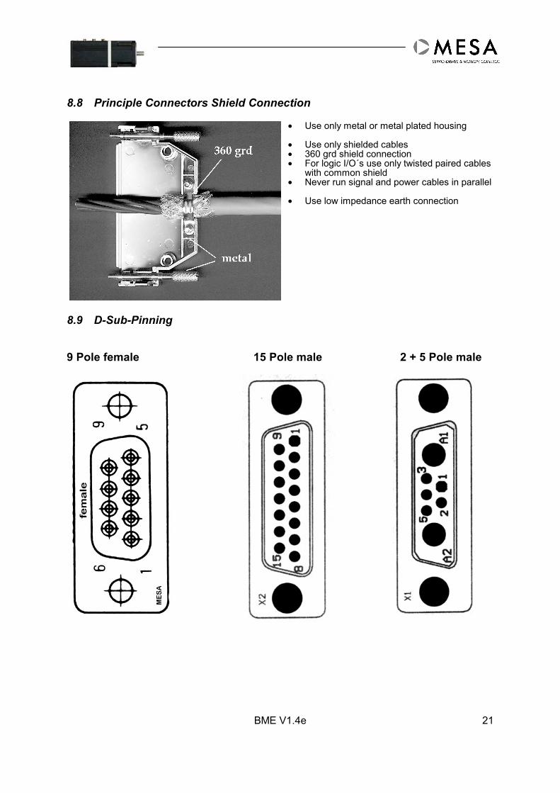
8.8 Principle Connectors Shield Connection
• Use only metal or metal plated housing • Use only shielded cables• 360 grd shield connection• For logic I/O´s use only twisted paired cables
with common shield• Never run signal and power cables in parallel • Use low impedance earth connection
8.9 D-Sub-Pinning
9 Pole female 15 Pole male 2 + 5 Pole male

BME V1.4e22
8.10 RS232 Connector
Serial connection to PC and machine signals to BME via X2 (like a T-connector)
8.11 ConstructionDSUB15
(female) to BMEX2
DSUB15(male)
to machine
DSUB9(female) to
PC
DSUB9 (male)via
non-modem cable
Remark
Pin Pin Pin Pin Signal name1 1 REF2 2 LIMIT+3 3 LIMIT-4 4 STOP5 5 IN+6 6 IN-7 7 IN 18 8 IN 39 9 IN 2
10 10 OUT 211 11 OUT 112 12 COMMON13 2 3 TX14 3 2 RX15 5 5 GND1
8.12 Non-modem Cable (typical)
DSUB9 (female) Cable 1x2 shielded DSUB9 (female)Pin Signal Pin Signal3 TX 2 RX2 RX 3 TX5 GND Shield 5 GND
T-Adapter Non-Modem-Cable
BME V1.4e 23
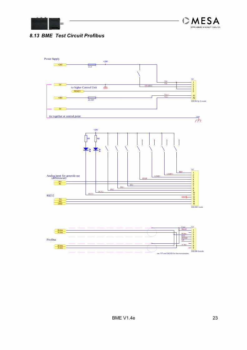
8.13 BME Test Circuit Profibus
123456789101112131415
X2
DSUB15 male
12345
A1A2
X1
DSUB-2p-2s male
123456789
X3
DSUB9 female
4k8
Profibus
B-lineA-line
B-lineA-line
ShieldCase
B-line
A-line
DGNDVP
use VP and DGND for bus termination
RXTX
GND
RS232
REFLIMIT+
LIMIT-STOP
IN1
4k8
IN3IN2
OUT2OUT1
READY
+24V
GND
GND
+24V
to higher Control Unit
4A MT
1A F
+48V
0V
+24V
0V
Vcc+Vcc-
Vh-Vh+
tie together at central point
Power Supply
case
RTS
ENABLE
IN+IN-
Analog input for generale use(differencial)

BME V1.4e24
8.14 BME Test Circuit CAN Bus
8.15
123456789101112131415
X2
DSUB15 male
12345
A1A2
X1
DSUB-2p-2s male
123456789
to X3
DSUB9 male
4k8
CANbus
CAN_LCAN_H
CAN_LCAN_H
Shield
Case
CAN_L
CAN_H
CGND
RXTX
GND
RS232
REFLIMIT+
LIMIT-STOP
IN1
4k8
IN3IN2
OUT2OUT1
READY
+24V
GND
GND
+24V
to higher Control Unit
4A MT
1A F
+48V
0V
+24V
0V
Vcc+Vcc-
Vh-Vh+
tie together at central point
Power Supply
case
ENABLE
IN+IN-
Analog input for generale use(differencial)

BME V1.4e 25
9 Earthing and Installation according to EMC Norms
9.1 General IndicationsIt is important that the installation of the BME/BDE is made according to the electrical safetyregulations and by a qualified person who is familiar with installation, assembly, commissioning andoperation of the equipment. National and local regulations must be respected.Please follow strictly the following instructions, it is important to assure the correct operation of theBME/BDE and so far of the complete machine.
The electromagnetic compatibility of the drive system depends - besides of the BME/BDE module - onthe following conditions:Total cable length - total capacity to ground.Low impedance Earthing of all components, Power supply and Control.Shielded cables and housings or shielded the complete control cabinet.Line tracing - distance between power, control and mains cables.
9.2 General RulesThe following regulations have to be respected:Installation of the devices in a closed metal control cabinet or machineUse the same ground potential for all components (motor, drive, control) by central earthing, pleasecheck it by measuring on commissioning.Contact the service for more information about the filter mode.In case of connection of the drive system with the general power supply system (or devices that do notcorrespond to EN 50082-2 regulations), an additional (common) mains filter is necessary.
9.3 Control Cabinet• The control cabinet must be equipped with a metal mounting panel with PE edge.• The mounting panel in the control cabinet is the reference station (GND) for all signals, it is
connected in a conductive way with the PE edge and the cabinet housing.• The control cabinet with the mounting panel and the machine must be earthed and connected (for
example with short ground copper strips).• The shields of all cables leaving the control cabinet must be connected 360° on the mounting panel,
no matter if they are earthed otherwise.• Outside of the control cabinet the cables should be led directly to the metal parts, as large distance
increases the unwanted emission. For special demands metal cable channels can be used.• If cables are led via additional terminals or switches, it is important to assure sufficient distance
between motor cable, mains cable and control cable. Due to the fact that the cables are notshielded on this position, especially emissions of the motor cables may have effects on othercables. The cables must be shielded directly before and after the interruption on the mountingpanel. This kind of interruptions should be avoided. If this is not possible, special shields (housing)can be mounted according to producer's advice.
9.4 Housing• The BME/BDE housing has to be connected via GN/YE cable with the PE edge in the control
cabinet.• In addition to the shield earthing you have to screw the housing of the BME/BDE in a conductive
way on the mounting panel of the control cabinet.
BME V1.4e26
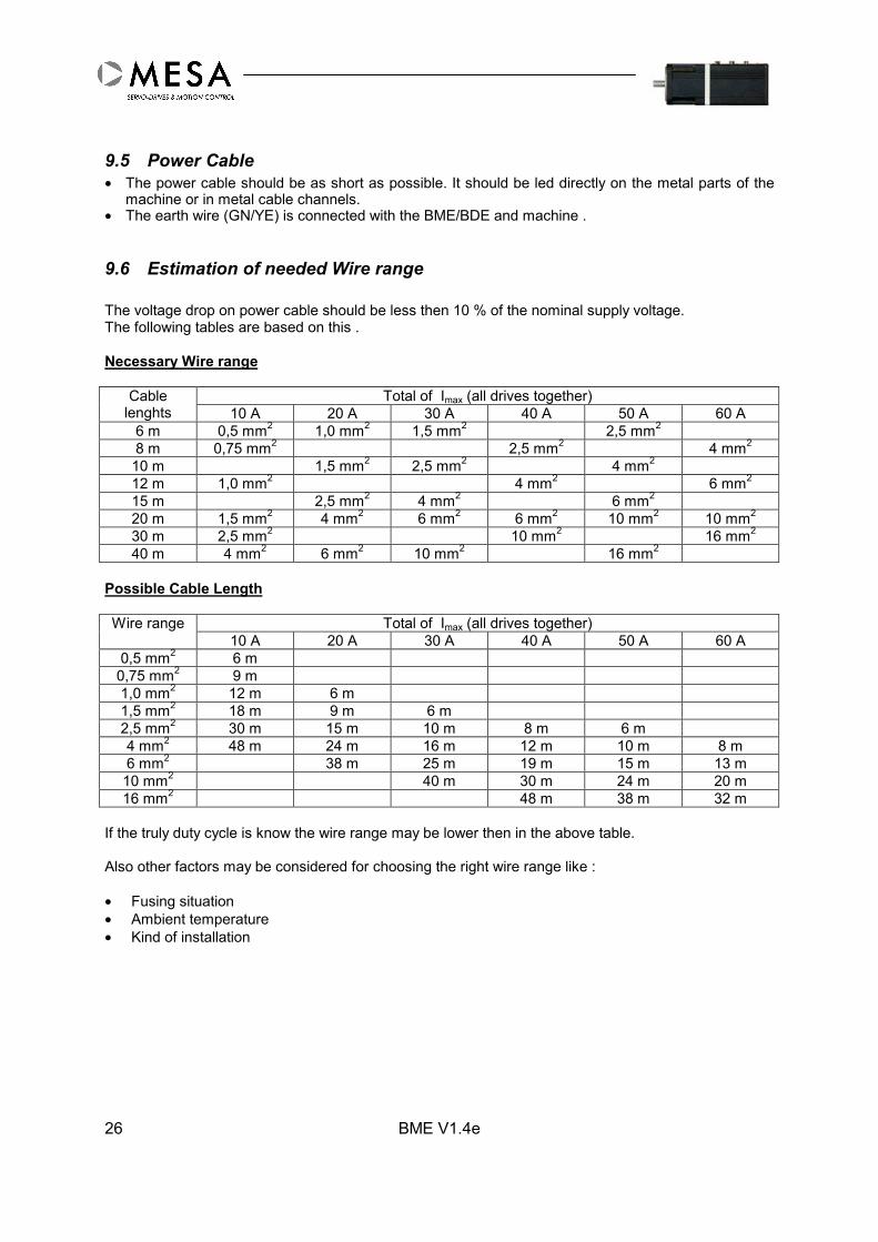
9.5 Power Cable• The power cable should be as short as possible. It should be led directly on the metal parts of the
machine or in metal cable channels.• The earth wire (GN/YE) is connected with the BME/BDE and machine .
9.6 Estimation of needed Wire range
The voltage drop on power cable should be less then 10 % of the nominal supply voltage.The following tables are based on this .
Necessary Wire range
Total of Imax (all drives together)Cablelenghts 10 A 20 A 30 A 40 A 50 A 60 A
6 m 0,5 mm2 1,0 mm2 1,5 mm2 2,5 mm2
8 m 0,75 mm2 2,5 mm2 4 mm2
10 m 1,5 mm2 2,5 mm2 4 mm2
12 m 1,0 mm2 4 mm2 6 mm2
15 m 2,5 mm2 4 mm2 6 mm2
20 m 1,5 mm2 4 mm2 6 mm2 6 mm2 10 mm2 10 mm2
30 m 2,5 mm2 10 mm2 16 mm2
40 m 4 mm2 6 mm2 10 mm2 16 mm2
Possible Cable Length
Total of Imax (all drives together)Wire range10 A 20 A 30 A 40 A 50 A 60 A
0,5 mm2 6 m0,75 mm2 9 m1,0 mm2 12 m 6 m1,5 mm2 18 m 9 m 6 m2,5 mm2 30 m 15 m 10 m 8 m 6 m4 mm2 48 m 24 m 16 m 12 m 10 m 8 m6 mm2 38 m 25 m 19 m 15 m 13 m10 mm2 40 m 30 m 24 m 20 m16 mm2 48 m 38 m 32 m
If the truly duty cycle is know the wire range may be lower then in the above table.
Also other factors may be considered for choosing the right wire range like :
• Fusing situation• Ambient temperature• Kind of installation

BME V1.4e 27
Diagram 1: Max. current in A for 4,8 V total voltage drop
Cable length (m)
Diagram 2: total voltage drop
Cable length (m) X Max. Current (A)
0
10
20
30
40
50
60
0 5 10 15 20 25 30 35 40
16 mm210 mm26,0 mm24,0 mm22,5 mm21,5 mm21,0 mm20,75 mm20,5 mm2
0,5 0,75 1,01,5
2,5
4,0
6,0
10
16
0,5
0,75
1,0
1,5
2,5
4,0
6,0
10
0,0
0,5
1,0
1,5
2,0
2,5
3,0
3,5
4,0
4,5
5,0
10 100 1000
0,5 mm20,75 mm21,0 mm21,5 mm22,5 mm24,0 mm26,0 mm210 mm216 mm2
20 30 40 50 60 80 200 300 400 600 800
16
10
6
4
2,5
1,5
1,00,750,5

BME V1.4e28
Netzteil
48 VdcServo-Drive
BME 05xx
Servo-Drive
BME 05xx
Ucc+
Uh+
Ucc-
Steuerung
Motion-
Erdungsschiene
Netzteil
24 VdcUh-
Ucc+
Uh+Ucc-
Uh-
Ucc+
Uh+Ucc-
Uh-
Ballast-Modul(optional)
LNPE
PEPE
Uh+Uh-PE
LN
PELN
PE
+-
+
-+
(weitere Regler / more Drives)
Schaltschrank / Cabinet Maschine / Mashine
PECEP
Power Supply
Power Supply
Verteilung / Power DistributionControl
9.7 Principle Wiring Diagram
Hints:
• Power supply must be grounded directly on the power supply and only there (central)• Sufficient +24 V Auxiliaiy supply (+24V)• UCC increase during braking, qualified power supply with braking system• Fusing of the BME/BDE see this Manual• Fusing according to the local / suppliers norm• Power cable short as possible
PE-Contact BME PE-Contact BDE

BME V1.4e 29
9.8 Control Cables• Control cables, especially those leaving the control cabinet, must be shielded or equipped with an
inter-filter (contact the producer). The shield has to be fixed on the BME/BDE and on the mountingpanel in the control cabinet. The shield of the control cable has to be connected with the metalconnector housing.
• Unshielded control cables should be avoided, also short connections should be twisted andshielded pairs.
9.9 BME/BDE CAN Bus Wiring
9.9.1 General
There are to ways for connecting the can bus.
We suggest to use dedicated CAN Bus cable and metallic shielded plugs for best results and highreliability. Any way the shield must be connected on both ends of the cable.Field bus cable are carry out in twisted pair shield version and should be dislocated from Power cables.The cable must be terminated with a 120 Ohm 0,25W resistor on both ends.Stubs are only allowed up to 30 cm.
Attention !Read also carefully the control builders manual for specific information.
9.9.2 Standard Version
Cable with two twisted pairs and commend shield
We suggest an equipotential bonding to minimise circulating currents in the shield.
Cable type order examplefor flexible typeLütze Superflex Bus © PUR 2x2x0,25mm²; Outside diameter 5,9mm; Order number :104220
Non flexible typeLapp 2x2x0,22mm²; Outside diameter 5,9mm; Order number 2170261

BME V1.4e30
9.9.3 Simplified Version
Cable with one twisted pair and commend shield
This version is only useful and leads to reasonable results if the BME/BDE are grouped together andthe equipotential bonding to minimise circulating currents in the shield is well made .
Cable type order examplefor flexible typeLütze Superflex Bus © PUR 1x2x0,25mm²; Outside diameter 6,0mm; Order number 104202Lapp UNITRONIC BUS-FD P CAN1x2x0,25mm²; Outside diameter 6,4mm; Order number2170260
Non flexible typeLapp UNITRONIC BUS CAN1x2x0,22mm²; Outside diameter 5,7mm; Order number2170272
BME V1.4e 31
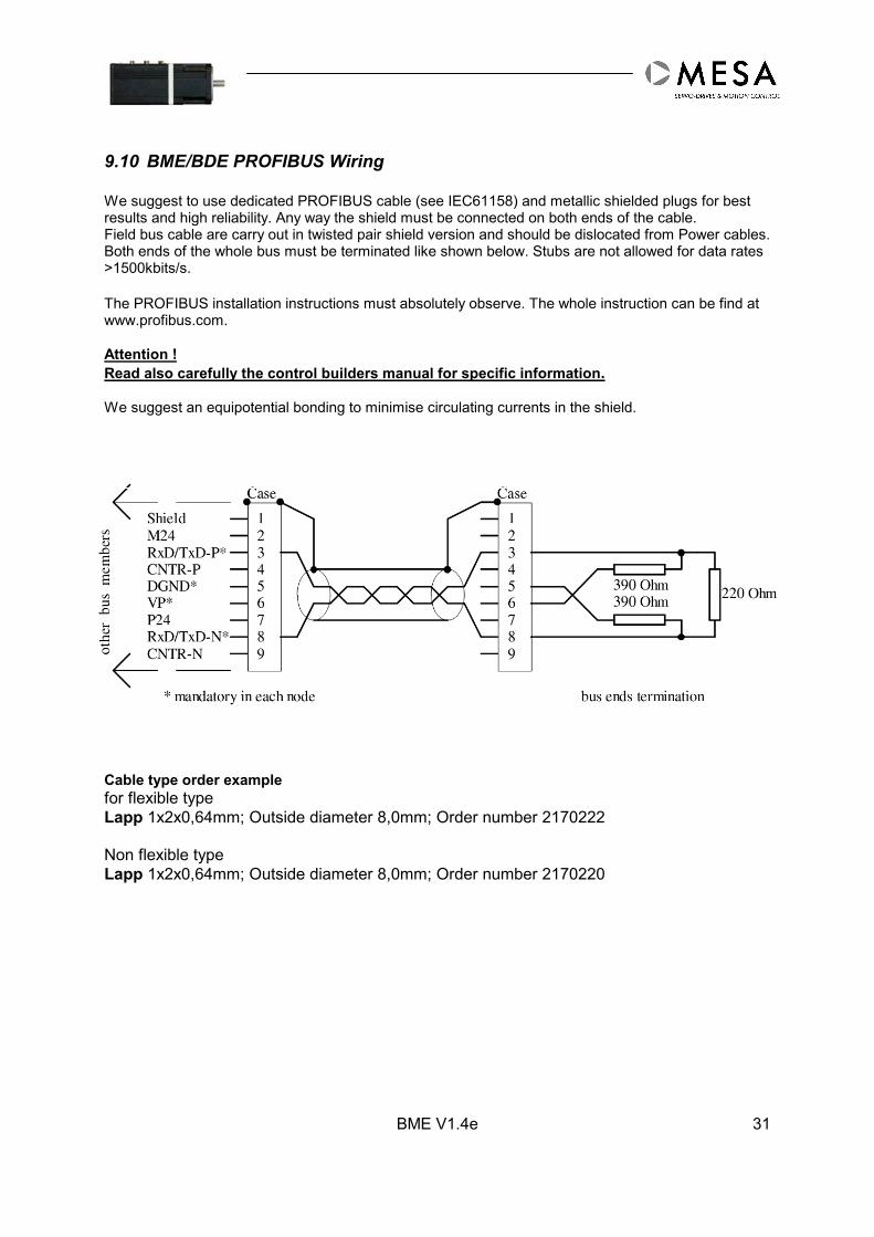
9.10 BME/BDE PROFIBUS Wiring
We suggest to use dedicated PROFIBUS cable (see IEC61158) and metallic shielded plugs for bestresults and high reliability. Any way the shield must be connected on both ends of the cable.Field bus cable are carry out in twisted pair shield version and should be dislocated from Power cables.Both ends of the whole bus must be terminated like shown below. Stubs are not allowed for data rates>1500kbits/s.
The PROFIBUS installation instructions must absolutely observe. The whole instruction can be find atwww.profibus.com.
Attention !Read also carefully the control builders manual for specific information.
We suggest an equipotential bonding to minimise circulating currents in the shield.
Cable type order examplefor flexible typeLapp 1x2x0,64mm; Outside diameter 8,0mm; Order number 2170222
Non flexible typeLapp 1x2x0,64mm; Outside diameter 8,0mm; Order number 2170220
BME V1.4e32
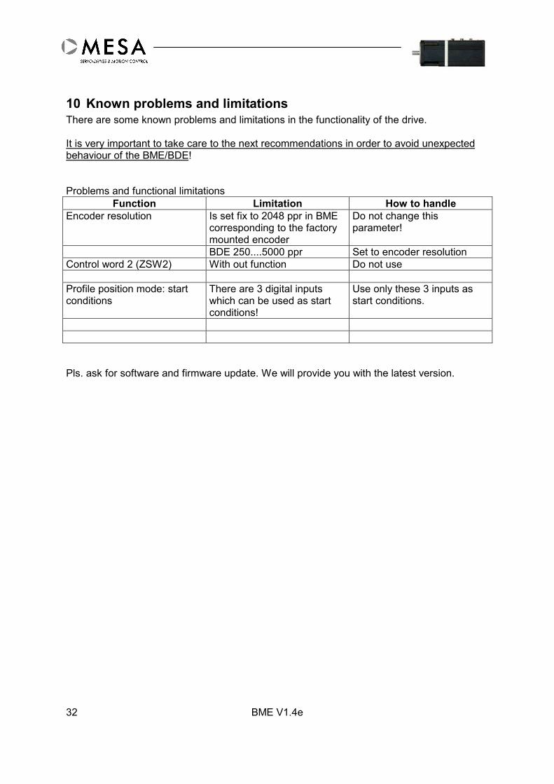
10 Known problems and limitationsThere are some known problems and limitations in the functionality of the drive.
It is very important to take care to the next recommendations in order to avoid unexpectedbehaviour of the BME/BDE!
Problems and functional limitationsFunction Limitation How to handle
Encoder resolution Is set fix to 2048 ppr in BMEcorresponding to the factorymounted encoder
Do not change thisparameter!
BDE 250....5000 ppr Set to encoder resolutionControl word 2 (ZSW2) With out function Do not use
Profile position mode: startconditions
There are 3 digital inputswhich can be used as startconditions!
Use only these 3 inputs asstart conditions.
Pls. ask for software and firmware update. We will provide you with the latest version.

BME V1.4e 33
11 Fault Finding- Quick Reference
Pls. use the RS 232 Interface for setup and diagnostic. Do not use mechanically damageddevice or devices with uncompleted housing.
Symptom Cause RemedyGENERAL
Mechanical damage Change deviceBME/BDE is too hot Check parameter
Check mounting
Power supply Fuse blows up Check wiring / polarityCheck power supply capacityReduce Imax.
Motor Part Noise Check speed and current loopparameterChange device
Shaft not free Change deviceMotor Brake Brake is closed OPEN brake
Power stage under voltage Check power supply capacityUse additional capacitorCheck wire diameter
Current loop Over current Check PI-parameterSet to default parameter
Speed loop Speed too low Check max speedCheck PI-parameterSet to default parameterCheck power voltage
Position loop Position overshoot Check max. speedCheck max. current
Fieldbus No communication Check wiringCheck parameters
RS 232 Check available COM-PortCheck baud rateSee also software manual
BME V1.4e34
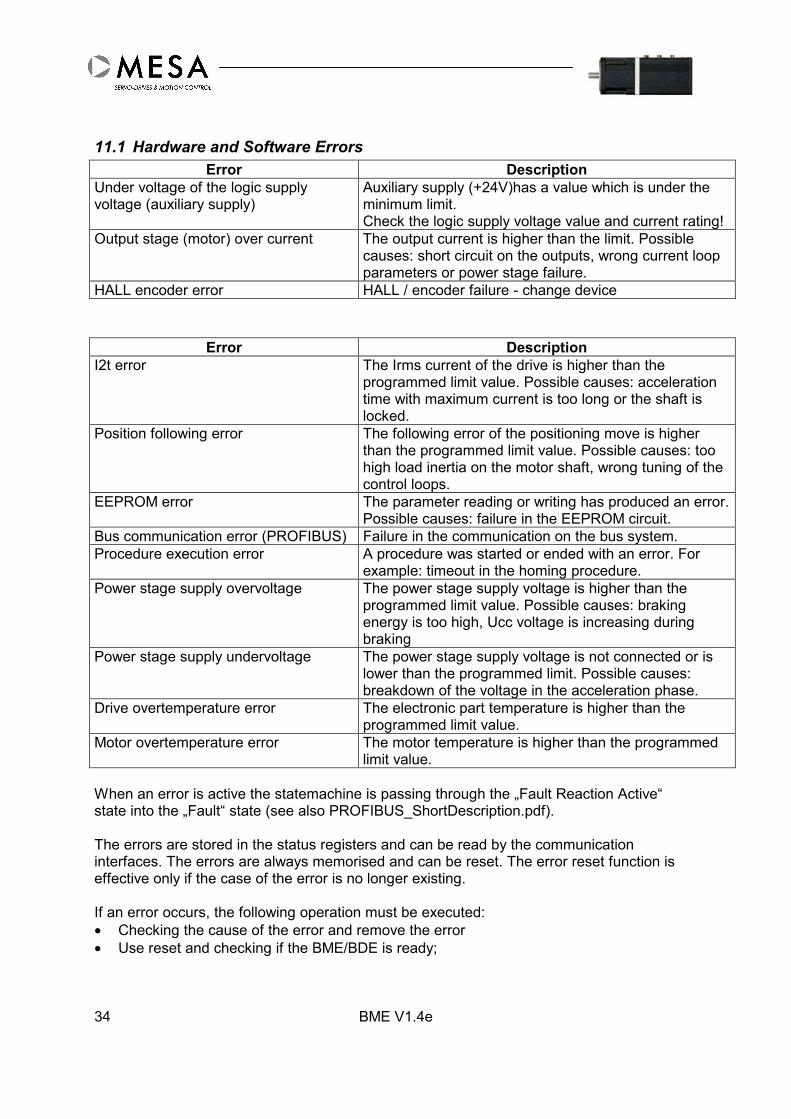
11.1 Hardware and Software ErrorsError Description
Under voltage of the logic supplyvoltage (auxiliary supply)
Auxiliary supply (+24V)has a value which is under theminimum limit.Check the logic supply voltage value and current rating!
Output stage (motor) over current The output current is higher than the limit. Possiblecauses: short circuit on the outputs, wrong current loopparameters or power stage failure.
HALL encoder error HALL / encoder failure - change device
Error DescriptionI2t error The Irms current of the drive is higher than the
programmed limit value. Possible causes: accelerationtime with maximum current is too long or the shaft islocked.
Position following error The following error of the positioning move is higherthan the programmed limit value. Possible causes: toohigh load inertia on the motor shaft, wrong tuning of thecontrol loops.
EEPROM error The parameter reading or writing has produced an error.Possible causes: failure in the EEPROM circuit.
Bus communication error (PROFIBUS) Failure in the communication on the bus system.Procedure execution error A procedure was started or ended with an error. For
example: timeout in the homing procedure.Power stage supply overvoltage The power stage supply voltage is higher than the
programmed limit value. Possible causes: brakingenergy is too high, Ucc voltage is increasing duringbraking
Power stage supply undervoltage The power stage supply voltage is not connected or islower than the programmed limit. Possible causes:breakdown of the voltage in the acceleration phase.
Drive overtemperature error The electronic part temperature is higher than theprogrammed limit value.
Motor overtemperature error The motor temperature is higher than the programmedlimit value.
When an error is active the statemachine is passing through the „Fault Reaction Active“state into the „Fault“ state (see also PROFIBUS_ShortDescription.pdf).
The errors are stored in the status registers and can be read by the communicationinterfaces. The errors are always memorised and can be reset. The error reset function iseffective only if the case of the error is no longer existing.
If an error occurs, the following operation must be executed:• Checking the cause of the error and remove the error• Use reset and checking if the BME/BDE is ready;

BME V1.4e 35
If the reset operation succeeded, the statemachine is passing into the „Switch On Disabled“state.
Some of the errors can be activated or deactivated (masked) for test purposes:• Position following error: if this error is masked the drive is continuing the move even the
following error is higher than the programmed maximum limit value. This maskingpossibility is useful during the testing and tuning process.
• Drive power stage supply under voltage error: if this error is masked (only a warning willbe generated) the drive is ready even if the power stage supply is not connected. Thismasking possibility is useful when the control is connecting the power stage supplyvoltage only if the drive is error free.
Attention !
If the power stage voltage is lower then 10 V a short circuit error will not be detected andgenerated.
Some of the errors have a supplementary timer functions in the error checking, that meansthe error will be active only after a time that is longer than the programmed time constant. Inthis way the control has the possibility to take some actions in order to avoid the error, in theprogrammed time window.• Drive over temperature error: the error function is activated only after the programmed
time expired;• Motor over temperature error: the error function is activated only after the programmed
time expired;
12 Additional Information
Software manual PROFIBUSSoftware manual CAN-BusSoftware manual MSD2BOMSD2BO (PC-Control software)

BME V1.4e36
13 BDE - Basic Drive Element
The BDE contains the same electronic like the BME. The BDE is for driving brushless andbrush servomotors with hall and encoder feedback.
BME V1.4e 37
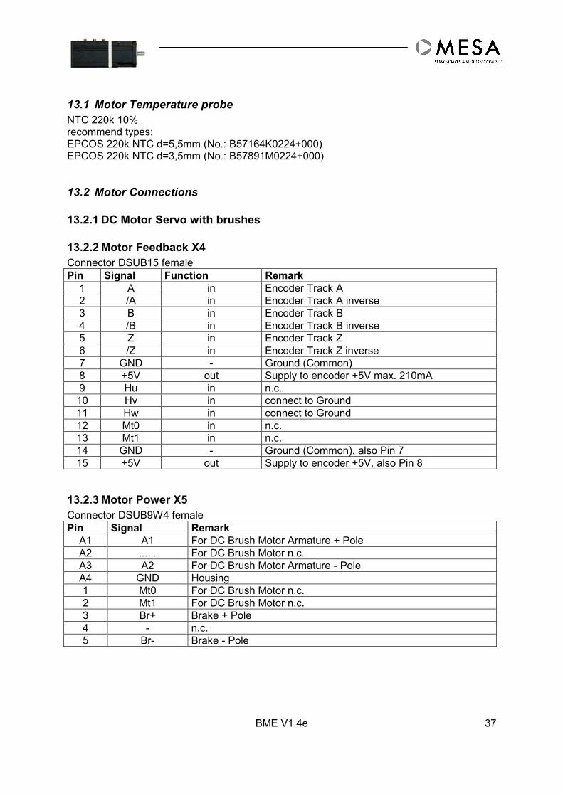
13.1 Motor Temperature probeNTC 220k 10%recommend types:EPCOS 220k NTC d=5,5mm (No.: B57164K0224+000)EPCOS 220k NTC d=3,5mm (No.: B57891M0224+000)
13.2 Motor Connections
13.2.1 DC Motor Servo with brushes
13.2.2 Motor Feedback X4Connector DSUB15 femalePin Signal Function Remark
1 A in Encoder Track A2 /A in Encoder Track A inverse3 B in Encoder Track B4 /B in Encoder Track B inverse5 Z in Encoder Track Z6 /Z in Encoder Track Z inverse7 GND - Ground (Common)8 +5V out Supply to encoder +5V max. 210mA9 Hu in n.c.10 Hv in connect to Ground11 Hw in connect to Ground12 Mt0 in n.c.13 Mt1 in n.c.14 GND - Ground (Common), also Pin 715 +5V out Supply to encoder +5V, also Pin 8
13.2.3 Motor Power X5Connector DSUB9W4 femalePin Signal Remark
A1 A1 For DC Brush Motor Armature + PoleA2 ...... For DC Brush Motor n.c.A3 A2 For DC Brush Motor Armature - PoleA4 GND Housing1 Mt0 For DC Brush Motor n.c.2 Mt1 For DC Brush Motor n.c.3 Br+ Brake + Pole4 - n.c.5 Br- Brake - Pole
BME V1.4e38
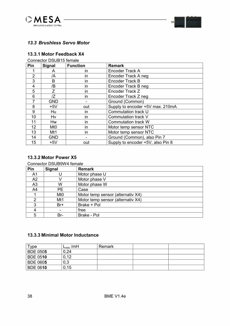
13.3 Brushless Servo Motor
13.3.1 Motor Feedback X4Connector DSUB15 femalePin Signal Function Remark
1 A in Encoder Track A2 /A in Encoder Track A neg3 B in Encoder Track B4 /B in Encoder Track B neg5 Z in Encoder Track Z6 /Z in Encoder Track Z neg7 GND - Ground (Common)8 +5V out Supply to encoder +5V max. 210mA9 Hu in Commutation track U10 Hv in Commutation track V11 Hw in Commutation track W12 Mt0 in Motor temp sensor NTC13 Mt1 in Motor temp sensor NTC14 GND - Ground (Common), also Pin 715 +5V out Supply to encoder +5V, also Pin 8
13.3.2 Motor Power X5Connector DSUB9W4 femalePin Signal Remark
A1 U Motor phase UA2 V Motor phase VA3 W Motor phase WA4 PE Case1 Mt0 Motor temp sensor (alternativ X4)2 Mt1 Motor temp sensor (alternativ X4)3 Br+ Brake + Pol4 - free5 Br- Brake - Pol
13.3.3 Minimal Motor Inductance
Type Lmin /mH RemarkBDE 0505 0,24BDE 0510 0,12BDE 0605 0,3BDE 0610 0,15

BME V1.4e 39
13.4 Mechanics
13.5 Optional Connector SetsFor cable production by customer (contains all connectors for X1 to X5):Connector Set for BDE PROFIBUS (MESA No.: 92.02270)Connector Set for BDE CANbus (MESA No.: 92.02271)
BME V1.4e40
13.6 EncoderThe default resolution of the encoder is 2048 ppr. Other values can set by software(MSD2BO). The BDE accepts encoder signals as RS485 level (A, /A,...) with maximal cablelength up to 5 meters. In this case the frequency of encoder pulses be allowed up to 700kHz(this match with about 17000 rpm at an 2048 ppr encoder).
13.7 Hall DeviceThe hall device delivers the commutation signals for brushless DC motors. The BDE acceptshall signals as TTL- or open collector signals. The signal sequence should be 120 degree.Encoder supply (+5V) together with hall device supply (+5V) should not exceed 210 mA.
13.8 Motor Brake ControlMotors stall brake fix the shaft if the brake is without current. The shaft can free turn if thebrake is supplied with 24VDC. The BDE can control the brake with the build in smart switch,therefore the brake has to be connected to connector X5, BR+ and BR.The auxiliary supply (+24VDC) support also the brake. The max. current should be notexceed 800 mA. The smart switch is electronically protected, in case of overload the switchwill be disabled – the output current drop to zero.

BME V1.4e 41

BME V1.4e42

BME V1.4e 43

BME V1.4e44
Date of issue: 05.02.2007
MESA Automation GmbH
MESA AUTOMATION GmbHINFRANOR GROUP - www.infranor.com
12045 BerlinMaybachufer 48-51
Phone: +49 (0)30 6139080 Fax: +49 (0)30 6231766http://www.mesa-berlin.de e-mail: [email protected]