Embed Size (px)
Citation preview
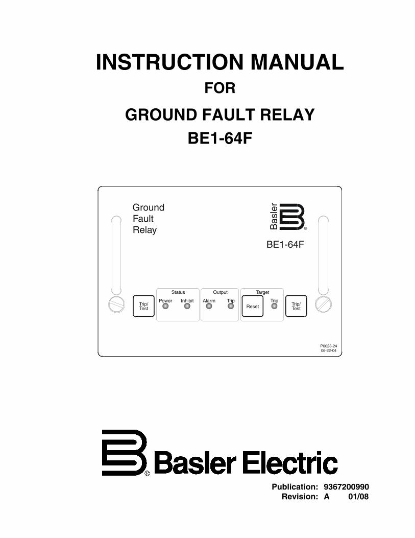
INSTRUCTION MANUAL FOR
GROUND FAULT RELAY BE1-64F
Publication: 9367200990 Revision: A 01/08

9367200990 Rev A BE1-64F Introduction i
INTRODUCTION This instruction manual provides information about the operation and installation of the BE1-64F Ground Fault Relay. To accomplish this, the following information is provided.
• General Information and Specifications
• Controls and Indicators
• Functional Description
• Installation
• Testing
WARNING!
To avoid personal injury or equipment damage, only qualified personnel should perform the procedures in this manual.
NOTE
Be sure that the relay is hard-wired to earth ground with no smaller than 12 AWG copper wire attached to the ground terminal on the rear of the unit case. When the relay is configured in a system with other devices, it is recommended to use a separate lead to the ground bus from each unit.
First Printing: March 2005
Printed in USA
© 2008 Basler Electric, Highland Illinois, USA
All Rights Reserved
January 2008
CONFIDENTIAL INFORMATION
of Basler Electric, Highland Illinois, USA. It is loaned for confidential use, subject to return on request, and with the mutual understanding that it will not be used in any manner detrimental to the interest of Basler Electric.
It is not the intention of this manual to cover all details and variations in equipment, nor does this manual provide data for every possible contingency regarding installation or operation. The availability and design of all features and options are subject to modification without notice. Should further information be required, contact Basler Electric.
BASLER ELECTRIC ROUTE 143, BOX 269
HIGHLAND IL 62249 USA http://www.basler.com, [email protected]
PHONE +1 618.654.2341 FAX +1 618.654.2351 ii BE1-64F Introduction 9367200990 Rev A

9367200990 Rev A BE1-64F Introduction iii
REVISION HISTORY
The following information provides a historical summary of the changes made to the BE1-64F hardware. The corresponding revisions made to this instruction manual (9367200990) are also summarized. Revisions are listed in chronological order.
Hardware Version and Date Change
C, 03/05 • Initial release D, 01/08 • Released part number 9367200104
Manual Revision and Date Change
—, 03/05 • Initial release A, 01/08 • Added coverage of part number 9367200104
• Added CE compliance information

This page intentionally left blank.
iv BE1-64F Introduction 9367200990 Rev A
9367200990 Rev A BE1-64F Introduction v
CONTENTS SECTION 1 • GENERAL INFORMATION ................................................................................................ 1-1 INTRODUCTION................................................................................................................................. 1-1 SPECIFICATIONS .............................................................................................................................. 1-1 Operating Power........................................................................................................................... 1-1 Field Voltage Input........................................................................................................................ 1-1 Block Input .................................................................................................................................... 1-1 Operating Time............................................................................................................................. 1-1 Sensitivity...................................................................................................................................... 1-1 Output Contacts............................................................................................................................ 1-2 Temperature ................................................................................................................................. 1-2 Type Tests .................................................................................................................................... 1-2 Agency Recognition...................................................................................................................... 1-2 CE Compliance............................................................................................................................. 1-3 Weight........................................................................................................................................... 1-3 Dimensions................................................................................................................................... 1-3
SECTION 2 • HUMAN-MACHINE INTERFACE ....................................................................................... 2-1 CONTROLS AND INDICATORS ........................................................................................................ 2-1
SECTION 3 • FUNCTIONAL DESCRIPTION ........................................................................................... 3-1 INTRODUCTION................................................................................................................................. 3-1 BE1-64F FUNCTION BLOCKS........................................................................................................... 3-1 Power Input................................................................................................................................... 3-1 Power Supplies............................................................................................................................. 3-1 Block Input .................................................................................................................................... 3-2 Field (F–) and Rotor Ground Interface ......................................................................................... 3-2 Current Detector and Reference .................................................................................................. 3-2 Alarm Comparator ........................................................................................................................ 3-2 Pre-Alarm Output Contact ............................................................................................................ 3-2 Trip Comparator ........................................................................................................................... 3-2 Gnd Trip Output Contact .............................................................................................................. 3-2 Loss of AC Power Alarm Output Contact ..................................................................................... 3-2 Target ........................................................................................................................................... 3-2 Reset ............................................................................................................................................ 3-2 Trip/Test........................................................................................................................................ 3-3
SECTION 4 • INSTALLATION .................................................................................................................. 4-1 MOUNTING......................................................................................................................................... 4-1 PRE-ALARM JUMPER ....................................................................................................................... 4-4 CONNECTIONS.................................................................................................................................. 4-5
SECTION 5 • TESTING ............................................................................................................................ 5-1 TESTING BE1-64F OPERATION ....................................................................................................... 5-1 Test Setup .................................................................................................................................... 5-1 Power-Up...................................................................................................................................... 5-2 Trip/Test Pushbuttons .................................................................................................................. 5-2 Target Retention........................................................................................................................... 5-2 Pre-Alarm...................................................................................................................................... 5-2 Ground Trip................................................................................................................................... 5-2 Block Input .................................................................................................................................... 5-2

This page intentionally left blank.
vi BE1-64F Introduction 9367200990 Rev A
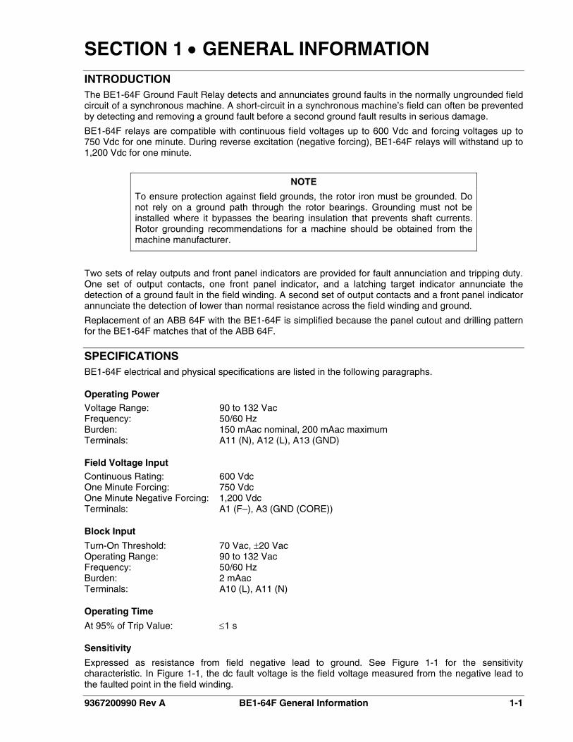
SECTION 1 • GENERAL INFORMATION INTRODUCTION The BE1-64F Ground Fault Relay detects and annunciates ground faults in the normally ungrounded field circuit of a synchronous machine. A short-circuit in a synchronous machine’s field can often be prevented by detecting and removing a ground fault before a second ground fault results in serious damage.
BE1-64F relays are compatible with continuous field voltages up to 600 Vdc and forcing voltages up to 750 Vdc for one minute. During reverse excitation (negative forcing), BE1-64F relays will withstand up to 1,200 Vdc for one minute.
NOTE
To ensure protection against field grounds, the rotor iron must be grounded. Do not rely on a ground path through the rotor bearings. Grounding must not be installed where it bypasses the bearing insulation that prevents shaft currents. Rotor grounding recommendations for a machine should be obtained from the machine manufacturer.
Two sets of relay outputs and front panel indicators are provided for fault annunciation and tripping duty. One set of output contacts, one front panel indicator, and a latching target indicator annunciate the detection of a ground fault in the field winding. A second set of output contacts and a front panel indicator annunciate the detection of lower than normal resistance across the field winding and ground.
Replacement of an ABB 64F with the BE1-64F is simplified because the panel cutout and drilling pattern for the BE1-64F matches that of the ABB 64F.
SPECIFICATIONS BE1-64F electrical and physical specifications are listed in the following paragraphs.
Operating Power Voltage Range: 90 to 132 Vac Frequency: 50/60 Hz Burden: 150 mAac nominal, 200 mAac maximum Terminals: A11 (N), A12 (L), A13 (GND)
Field Voltage Input Continuous Rating: 600 Vdc One Minute Forcing: 750 Vdc One Minute Negative Forcing: 1,200 Vdc Terminals: A1 (F–), A3 (GND (CORE))
Block Input
Turn-On Threshold: 70 Vac, ±20 Vac Operating Range: 90 to 132 Vac Frequency: 50/60 Hz Burden: 2 mAac Terminals: A10 (L), A11 (N)
Operating Time
At 95% of Trip Value: ≤1 s
Sensitivity
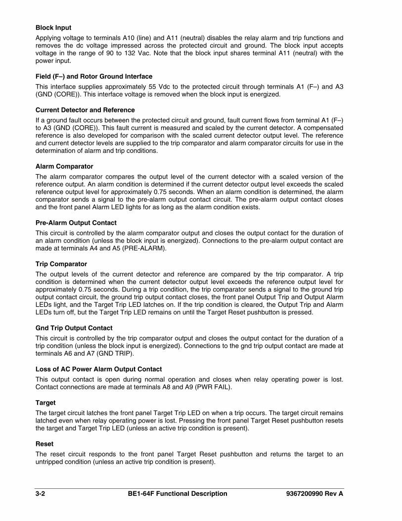
Expressed as resistance from field negative lead to ground. See Figure 1-1 for the sensitivity characteristic. In Figure 1-1, the dc fault voltage is the field voltage measured from the negative lead to the faulted point in the field winding.
9367200990 Rev A BE1-64F General Information 1-1
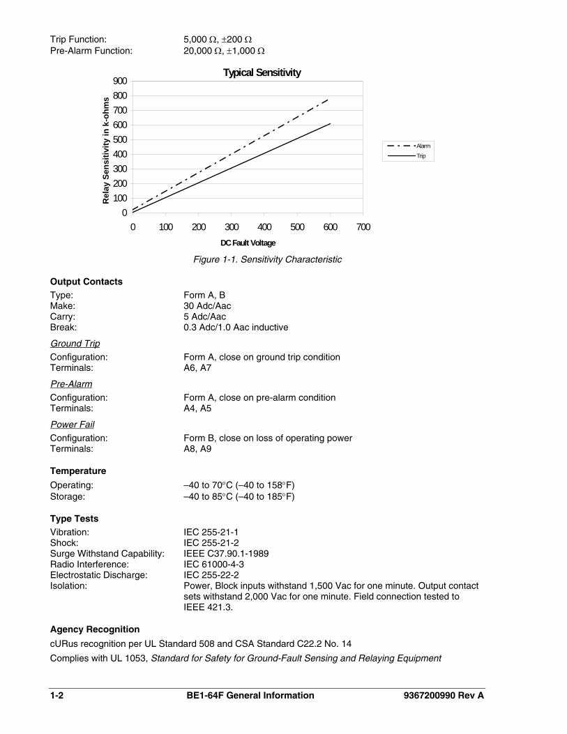
Trip Function: 5,000 Ω, ±200 Ω Pre-Alarm Function: 20,000 Ω, ±1,000 Ω
Typical Sensitivity
0100200300400500600700800900
0 100 200 300 400 500 600 700DC Fault Voltage
Rel
ay S
ensi
tivity
in k
-ohm
s
Alarm
Trip
Figure 1-1. Sensitivity Characteristic
Output Contacts Type: Form A, B Make: 30 Adc/Aac Carry: 5 Adc/Aac Break: 0.3 Adc/1.0 Aac inductive
Ground Trip
Configuration: Form A, close on ground trip condition Terminals: A6, A7
Pre-Alarm
Configuration: Form A, close on pre-alarm condition Terminals: A4, A5
Power Fail
Configuration: Form B, close on loss of operating power Terminals: A8, A9
Temperature
Operating: –40 to 70°C (–40 to 158°F) Storage: –40 to 85°C (–40 to 185°F)
Type Tests Vibration: IEC 255-21-1 Shock: IEC 255-21-2 Surge Withstand Capability: IEEE C37.90.1-1989 Radio Interference: IEC 61000-4-3 Electrostatic Discharge: IEC 255-22-2 Isolation: Power, Block inputs withstand 1,500 Vac for one minute. Output contact
sets withstand 2,000 Vac for one minute. Field connection tested to IEEE 421.3.
Agency Recognition
cURus recognition per UL Standard 508 and CSA Standard C22.2 No. 14
Complies with UL 1053, Standard for Safety for Ground-Fault Sensing and Relaying Equipment
1-2 BE1-64F General Information 9367200990 Rev A
9367200990 Rev A BE1-64F General Information 1-3
CE Compliance
Meets or exceeds the standards required for distribution in the European community
Weight Unit: 4.65 lb (2.11 kg) Shipping: 6.10 lb (2.77 kg)
Dimensions H x W x D: 4.875 x 7.0 x 8.693 in (123.8 x 177.8 x 220.8 mm)

This page intentionally left blank.
1-4 BE1-64F General Information 9367200990 Rev A
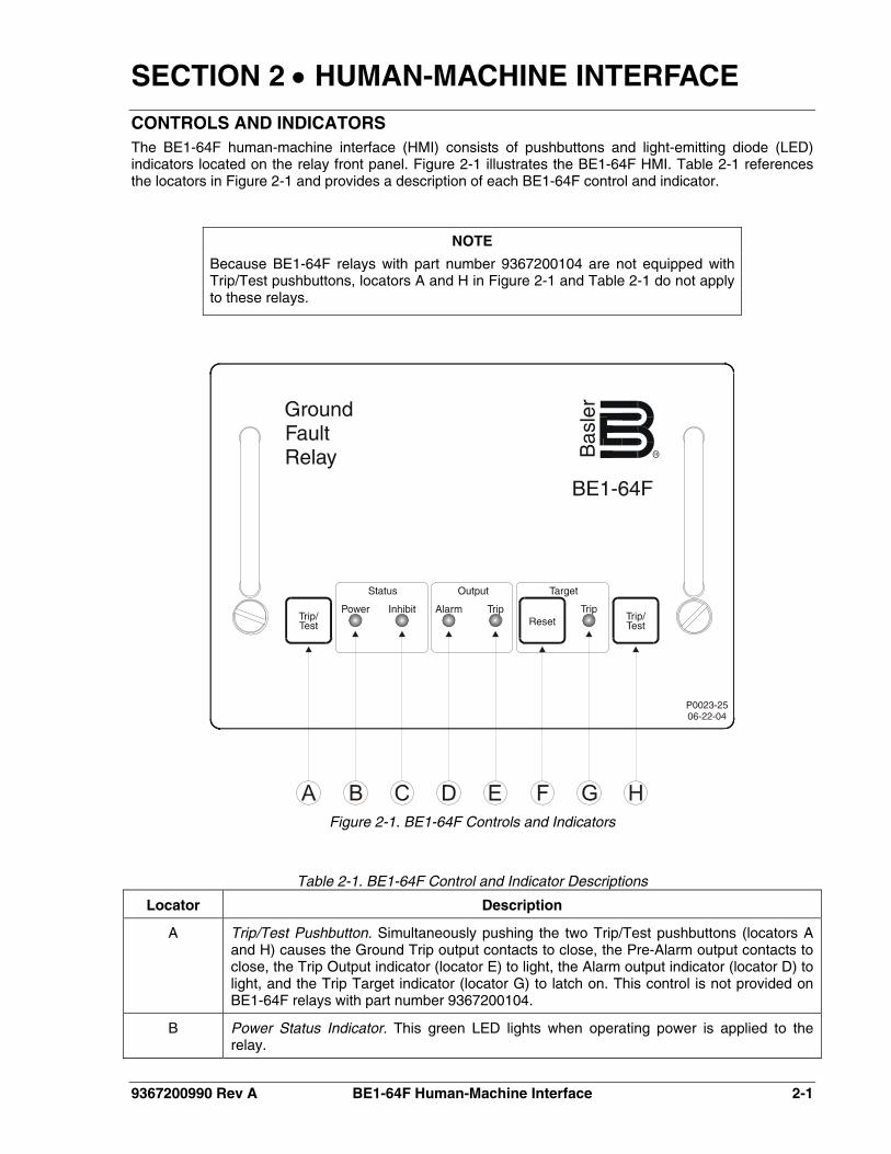
SECTION 2 • HUMAN-MACHINE INTERFACE CONTROLS AND INDICATORS The BE1-64F human-machine interface (HMI) consists of pushbuttons and light-emitting diode (LED) indicators located on the relay front panel. Figure 2-1 illustrates the BE1-64F HMI. Table 2-1 references the locators in Figure 2-1 and provides a description of each BE1-64F control and indicator.
NOTE
Because BE1-64F relays with part number 9367200104 are not equipped with Trip/Test pushbuttons, locators A and H in Figure 2-1 and Table 2-1 do not apply to these relays.
Figure 2-1. BE1-64F Controls and Indicators
Table 2-1. BE1-64F Control and Indicator Descriptions
Locator Description
A Trip/Test Pushbutton. Simultaneously pushing the two Trip/Test pushbuttons (locators A and H) causes the Ground Trip output contacts to close, the Pre-Alarm output contacts to close, the Trip Output indicator (locator E) to light, the Alarm output indicator (locator D) to light, and the Trip Target indicator (locator G) to latch on. This control is not provided on BE1-64F relays with part number 9367200104.
B Power Status Indicator. This green LED lights when operating power is applied to the relay.
9367200990 Rev A BE1-64F Human-Machine Interface 2-1
2-2 BE1-64F Human-Machine Interface 9367200990 Rev A
Locator Description
C Inhibit Status Indicator. This red LED lights when the Block input is energized and BE1-64F tripping is disabled.
D Alarm Output Indicator. This red LED lights when the relay senses less than 20 kΩ of resistance from the machine field to ground and the Pre-Alarm output contacts close. This function may be disabled by a user-adjustable jumper located on the draw-out printed circuit board. See Section 4, Installation for the jumper location and jumper placement instructions.
E Trip Output Indicator. This red LED lights when the relay senses less than 5 kΩ of resistance from the machine field to ground and the Ground Trip output contacts close.
F Target Reset Pushbutton. This control is pressed to reset the latching Trip Target indicator (locator G) after a ground in the machine field circuit has been removed.
G Trip Target Indicator. This red indicator latches on when the Ground Trip output closes due to a ground in the machine field circuit. Target status is maintained when relay operating power is removed. When relay operating power is restored, the Trip Target LED indicates the target status prior to the removal of operating power. The Trip Target indicator is reset by operating the Target Reset pushbutton (locator F).
H Trip/Test Pushbutton. Simultaneously pushing the two Trip/Test pushbuttons (locators A and H) causes the Ground Trip output contacts to close, the Pre-Alarm output contacts to close, the Trip Output indicator (locator E) to light, the Alarm output indicator (locator D) to light, and the Trip Target indicator (locator G) to latch on. This control is not provided on BE1-64F relays with part number 9367200104.
SECTION 3 • FUNCTIONAL DESCRIPTION INTRODUCTION The BE1-64F Ground Fault Relay detects and annunciates ground faults in the normally ungrounded field circuit of a synchronous machine.
The BE1-64F applies a dc voltage between the field circuit and ground. When a ground fault occurs, the BE1-64F detects the flow of current and annunciates the fault. Detection of ground faults by the BE1-64F depends upon the nominal field voltage and the location of the ground fault in the field winding.
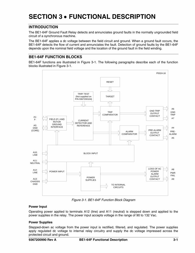
BE1-64F FUNCTION BLOCKS BE1-64F functions are illustrated in Figure 3-1. The following paragraphs describe each of the function blocks illustrated in Figure 3-1.
POWER INPUT
BLOCK INPUT
LOSS OF AC POWER ALARM
OUTPUT CONTACT
POWER SUPPLIES
FIELD (F-) AND ROTOR
GROUND INTERFACE
CURRENT DETECTOR AND
REFERENCE
TRIP COMPARATOR
ALARM COMPARATOR
GND TRIP OUTPUT
CONTACT
PRE-ALARM OUTPUT
CONTACT
TRIP/ TEST(Not supplied on P/N 9367200104)
TARGET
RESET
TO INTERNAL CIRCUITS
A1:F-
A3:GND
(CORE)
A10:LINE
A11:NEUTRAL
A12:LINE
A13:CHASSIS
GND
A6
PRE-ALARM
A4
A5
A8
A9
GNDTRIP
PWRFAIL
A7
P0024-16
Figure 3-1. BE1-64F Function Block Diagram
Power Input
Operating power applied to terminals A12 (line) and A11 (neutral) is stepped down and applied to the power supplies in the relay. The power input accepts voltage in the range of 90 to 132 Vac.
Power Supplies
Stepped-down ac voltage from the power input is rectified, filtered, and regulated. The power supplies apply regulated dc voltage to internal relay circuitry and supply the dc voltage impressed across the protected circuit and ground.
9367200990 Rev A BE1-64F Functional Description 3-1
3-2 BE1-64F Functional Description 9367200990 Rev A
Block Input
Applying voltage to terminals A10 (line) and A11 (neutral) disables the relay alarm and trip functions and removes the dc voltage impressed across the protected circuit and ground. The block input accepts voltage in the range of 90 to 132 Vac. Note that the block input shares terminal A11 (neutral) with the power input.
Field (F–) and Rotor Ground Interface
This interface supplies approximately 55 Vdc to the protected circuit through terminals A1 (F–) and A3 (GND (CORE)). This interface voltage is removed when the block input is energized.
Current Detector and Reference
If a ground fault occurs between the protected circuit and ground, fault current flows from terminal A1 (F–) to A3 (GND (CORE)). This fault current is measured and scaled by the current detector. A compensated reference is also developed for comparison with the scaled current detector output level. The reference and current detector levels are supplied to the trip comparator and alarm comparator circuits for use in the determination of alarm and trip conditions.
Alarm Comparator
The alarm comparator compares the output level of the current detector with a scaled version of the reference output. An alarm condition is determined if the current detector output level exceeds the scaled reference output level for approximately 0.75 seconds. When an alarm condition is determined, the alarm comparator sends a signal to the pre-alarm output contact circuit. The pre-alarm output contact closes and the front panel Alarm LED lights for as long as the alarm condition exists.
Pre-Alarm Output Contact
This circuit is controlled by the alarm comparator output and closes the output contact for the duration of an alarm condition (unless the block input is energized). Connections to the pre-alarm output contact are made at terminals A4 and A5 (PRE-ALARM).
Trip Comparator
The output levels of the current detector and reference are compared by the trip comparator. A trip condition is determined when the current detector output level exceeds the reference output level for approximately 0.75 seconds. During a trip condition, the trip comparator sends a signal to the ground trip output contact circuit, the ground trip output contact closes, the front panel Output Trip and Output Alarm LEDs light, and the Target Trip LED latches on. If the trip condition is cleared, the Output Trip and Alarm LEDs turn off, but the Target Trip LED remains on until the Target Reset pushbutton is pressed.
Gnd Trip Output Contact
This circuit is controlled by the trip comparator output and closes the output contact for the duration of a trip condition (unless the block input is energized). Connections to the gnd trip output contact are made at terminals A6 and A7 (GND TRIP).
Loss of AC Power Alarm Output Contact
This output contact is open during normal operation and closes when relay operating power is lost. Contact connections are made at terminals A8 and A9 (PWR FAIL).
Target
The target circuit latches the front panel Target Trip LED on when a trip occurs. The target circuit remains latched even when relay operating power is lost. Pressing the front panel Target Reset pushbutton resets the target and Target Trip LED (unless an active trip condition is present).
Reset
The reset circuit responds to the front panel Target Reset pushbutton and returns the target to an untripped condition (unless an active trip condition is present).
9367200990 Rev A BE1-64F Functional Description 3-3
Trip/Test
The trip/test circuit tests relay functionality by internally simulating a trip condition. A trip or test is initiated by pressing the two front panel Trip/Test pushbuttons simultaneously. The simulated trip condition is removed when either or both of the Trip/Test pushbuttons are released. The Target Trip LED remains lit until the Target Reset pushbutton is pressed.
The trip/test function is not provided on BE1-64F relays with part number 9367200104.

This page intentionally left blank.
3-4 BE1-64F Functional Description 9367200990 Rev A
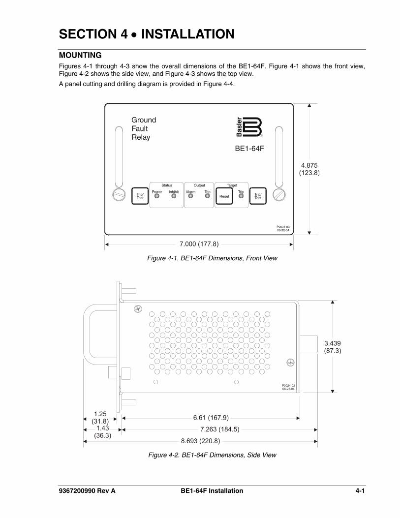
SECTION 4 • INSTALLATION MOUNTING Figures 4-1 through 4-3 show the overall dimensions of the BE1-64F. Figure 4-1 shows the front view, Figure 4-2 shows the side view, and Figure 4-3 shows the top view.
A panel cutting and drilling diagram is provided in Figure 4-4.
Figure 4-1. BE1-64F Dimensions, Front View
Figure 4-2. BE1-64F Dimensions, Side View
9367200990 Rev A BE1-64F Installation 4-1
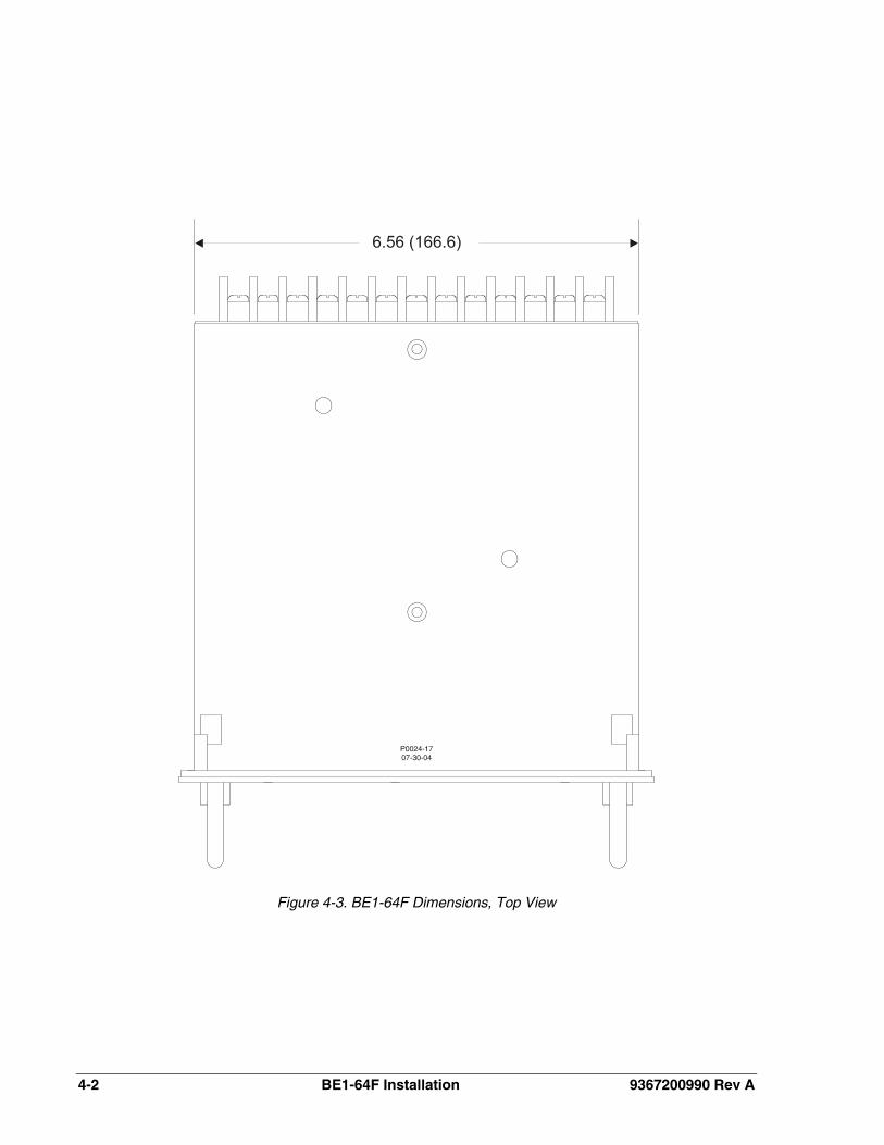
Figure 4-3. BE1-64F Dimensions, Top View
4-2 BE1-64F Installation 9367200990 Rev A
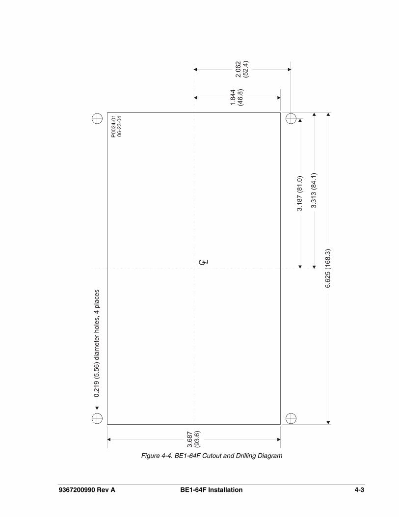
Figure 4-4. BE1-64F Cutout and Drilling Diagram
9367200990 Rev A BE1-64F Installation 4-3
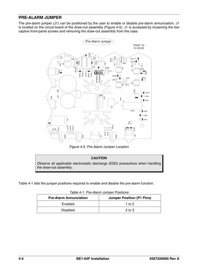
PRE-ALARM JUMPER The pre-alarm jumper (J1) can be positioned by the user to enable or disable pre-alarm annunciation. J1 is located on the circuit board of the draw-out assembly (Figure 4-5). J1 is accessed by loosening the two captive front-panel screws and removing the draw-out assembly from the case.
Figure 4-5. Pre-Alarm Jumper Location
CAUTION
Observe all applicable electrostatic discharge (ESD) precautions when handling the draw-out assembly.
Table 4-1 lists the jumper positions required to enable and disable the pre-alarm function.
Table 4-1. Pre-Alarm Jumper Positions
Pre-Alarm Annunciation Jumper Position (P1 Pins)
Enabled 1 to 2
Disabled 2 to 3
4-4 BE1-64F Installation 9367200990 Rev A
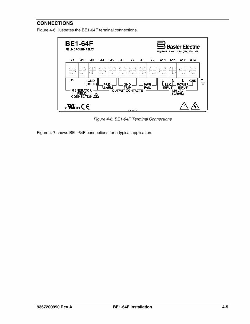
CONNECTIONS Figure 4-6 illustrates the BE1-64F terminal connections.
Figure 4-6. BE1-64F Terminal Connections
Figure 4-7 shows BE1-64F connections for a typical application.
9367200990 Rev A BE1-64F Installation 4-5
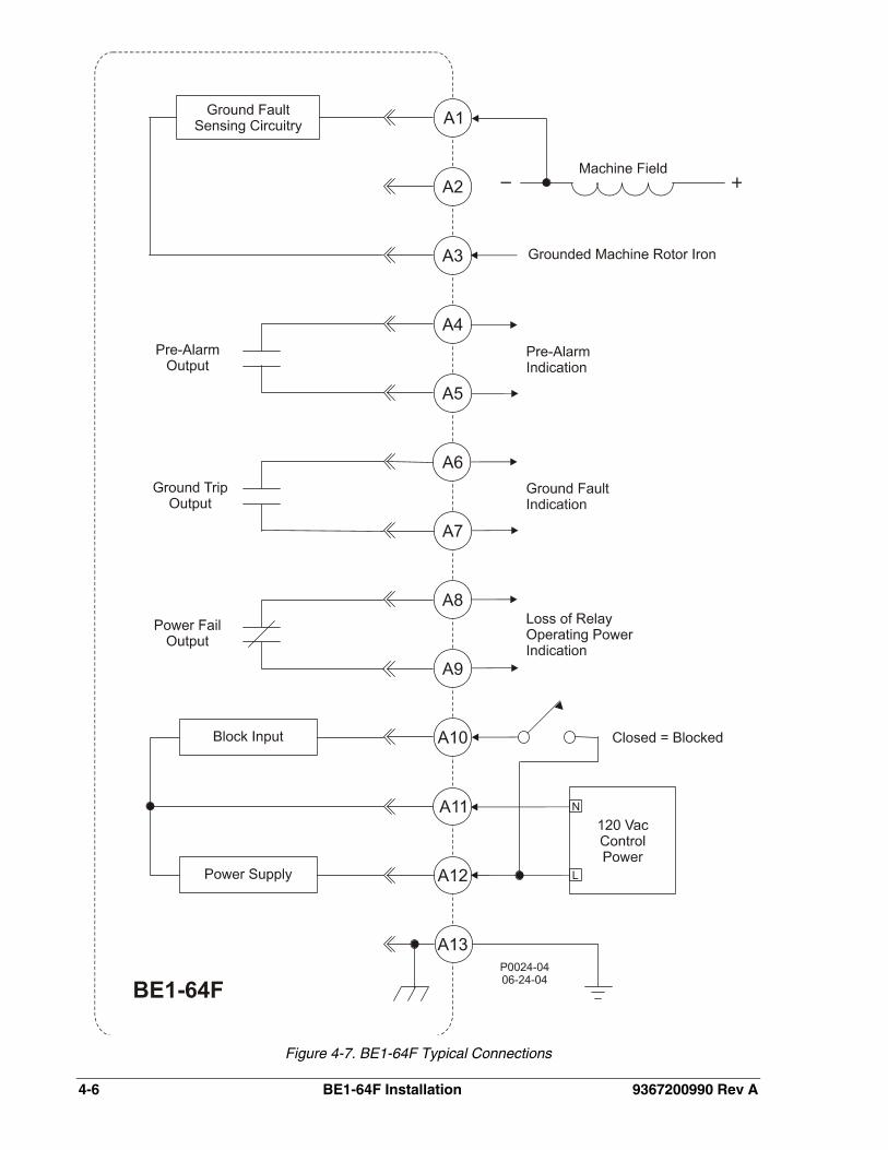
Figure 4-7. BE1-64F Typical Connections
4-6 BE1-64F Installation 9367200990 Rev A
SECTION 5 • TESTING TESTING BE1-64F OPERATION To test BE1-64F operation, perform the following procedures.
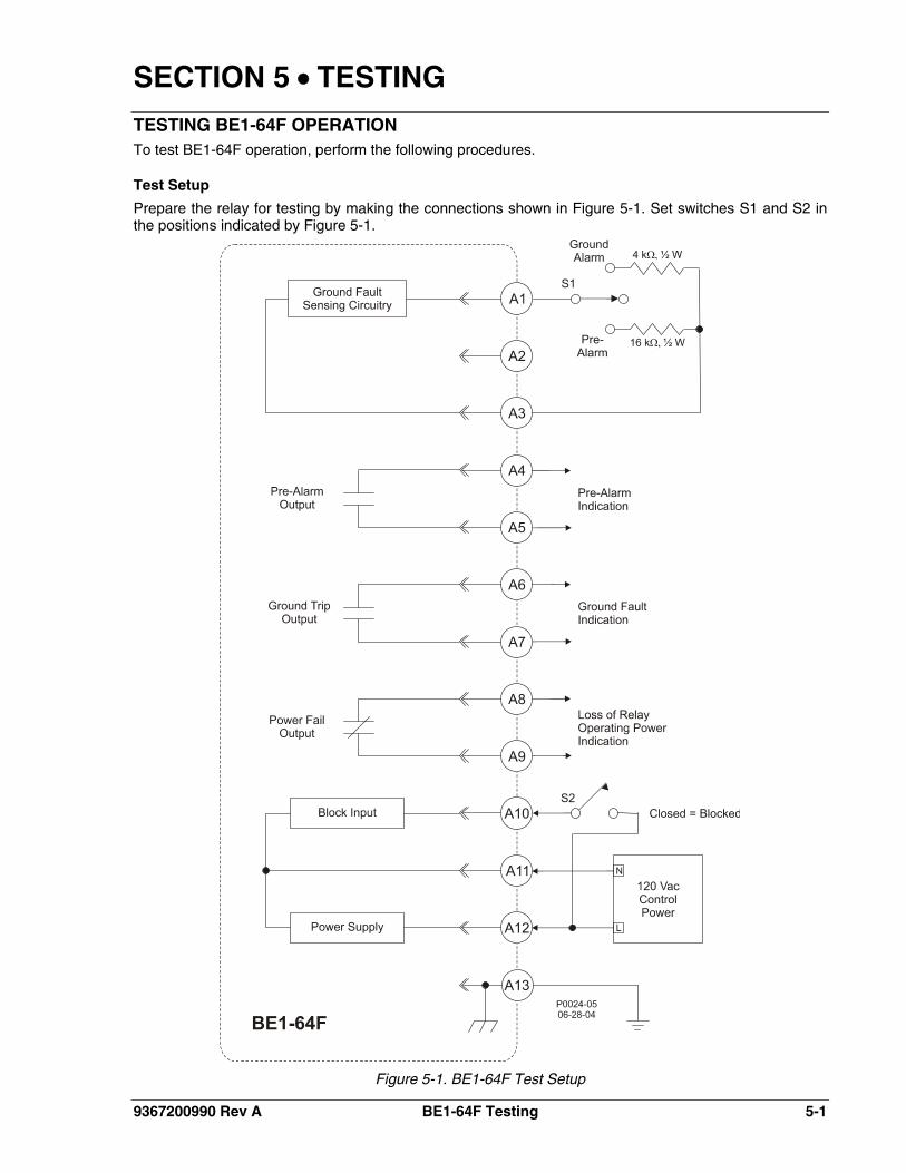
Test Setup
Prepare the relay for testing by making the connections shown in Figure 5-1. Set switches S1 and S2 in the positions indicated by Figure 5-1.
Figure 5-1. BE1-64F Test Setup
9367200990 Rev A BE1-64F Testing 5-1
5-2 BE1-64F Testing 9367200990 Rev A
Power-Up
1. Prior to applying relay operating power, verify that the Power Fail output contacts at terminals A8 and A9 are closed.
2. Apply 120 Vac operating power to terminals A11 and A12. The Power Fail output contacts should open.
3. Press the Target Reset pushbutton. All front panel indicators should be off except for the green Power Status LED. The Pre-Alarm output contacts at terminals A4 and A5 and the Ground Trip output contacts at terminals A6 and A7 should be open.
Trip/Test Pushbuttons
BE1-64F relays with part number 9367200104 are not equipped with the Trip/Test function and push-buttons. The following steps do not apply to relays with this part number.
1. Press and hold both front panel Trip/Test pushbuttons. The Pre-Alarm output contacts (terminals A4 and A5) and Ground Trip output contacts (terminals A6 and A7) should close, the front panel Alarm Output and Trip Output LEDs should light, and the Trip Target LED should latch on.
2. Release the Trip/Test pushbuttons. The Pre-Alarm output contacts and Ground Trip output contacts should open and the Alarm Output and Trip Output LEDs should turn off. The latching Trip Target LED should remain on.
Target Retention
1. Perform steps 1 and 2 of Trip/Test Pushbuttons so that the Trip Target LED is latched on.
2. Remove operating power from the relay. Wait several seconds and then apply relay operating power. Verify that target status is retained by observing that the Trip Target LED lights when relay operating power is restored.
3. Reset the Trip Target LED by pressing the Target Reset pushbutton.
Pre-Alarm
1. Place switch S1 in the Pre-Alarm position so that the 16 kΩ resistor is connected between relay terminals A1 and A3. The Pre-Alarm output contacts should close and the front panel Alarm Output LED should light.
2. Return switch S1 to the position shown in Figure 5-1. The Pre-Alarm output contacts should open and the Alarm Output LED should turn off.
Ground Trip
1. Place switch S1 in the Ground Alarm position so that the 4 kΩ resistor is connected between terminals A1 and A3. The Ground Trip output contacts should close, the Trip Output LED should light, and the Trip Target LED should latch on.
2. Return switch S1 to the position shown in Figure 5-1. The Ground Trip output contacts should open and the Trip Output LED should turn off. The Trip Target LED will remain lit until the Target Reset pushbutton is pressed.
Block Input
1. Place switch S2 in the closed position.
2. Place switch S1 in the Pre-Alarm position. The relay should not respond with an output contact closure or a front panel indication.
3. Place S1 in the Ground Alarm position. The relay should not respond with an output contact closure or a front panel indication.
4. Open switch S2 and verify that the relay responds to the ground alarm condition.

ROUTE 143, BOX 269 HIGHLAND, IL 62249 USA
http://www.basler.com, [email protected] PHONE +1 618-654-2341 FAX +1 618-654-2351