Embed Size (px)
Citation preview

BATTERY TEST CENTREREPORT 1
September 2016

ii ITP/AU – September 2016
Battery Test Centre - Public Report 1
About ITP Renewables
ITP is a global leader in energy engineering, consulting and project management, with expertise spanning the breadth of renewable energy, storage, efficiency, system design and policy.
We work with our clients at the local level to provide a unique combination of experienced energy engineers, specialist strategic advisors and experts in economics, financial analysis and policy. Our experts have professional backgrounds in industry, academia and government.
Since opening our Canberra office in 2003 we have expanded into New South Wales, South Australia and New Zealand.
ITP are proud to be part of the international ITP Energised Group—one of the world’s largest, most respected and experienced specialist engineering consultancies focussed on renewable energy, energy efficiency and climate change.
Established in the United Kingdom in 1981, the Group was among the first dedicated renewable energy consultancies. In addition to the UK it maintains a presence in Spain, Portugal, India, China, Argentina and Kenya, as well as our ITP offices in Australia and New Zealand.
Globally, the Group employs experts in all aspects of renewable energy, including photovoltaics (PV), solar thermal, marine, wind, hydro (micro to medium scale), hybridisation and biofuels.
About this report
The Lithium Ion Battery Test Centre program involves performance testing of six lithium-ion batteries, one lead acid battery and one advanced lead acid battery. The project is supported by a $450,000 grant from the Australian Renewable Energy Agency. This report provides analysis and discussion of the process of installing the batteries and testing data collected between July 2016 and September 2016.

ITP/AU – September 2016 iii
Battery Test Centre - Public Report 1
Report Control Record
Document prepared by:ITP Renewables Level 1, Suite 1, 19 -23 Moore St, Turner, ACT, 2612, Australia
PO Box 6127, O’Connor, ACT, 2602, Australia Tel. +61 2 6257 3511 Fax. +61 2 6257 3611 E-mail : [email protected] http://www.itpau.com.au
Document Control Report title Battery Test Centre - Public Report 1
Client Contract No. n/a ITP Project Number AU
File path n/a
Client Public Client Contact n/a
A person or organisation choosing to use documents prepared by IT Power (Australia) Pty Ltd accepts the following:
a) Conclusions and figures presented in draft documents are subject to change. IT Power (Australia) Pty Ltd accepts no responsibility for their use outside of the original report.
b) While reasonable efforts have been made to ensure the accuracy, completeness and reliability of the material contained in the document, the authors accept no liability for the accuracy of or inferences from the material contained in this publication, or for any action as a result of any person’s or group’s interpretations, deductions, conclusions in relying on this material.
c) The document is only to be used for purposes explicitly agreed to by IT Power (Australia) Pty Ltd. d) All responsibility and risks associated with the use of this report lie with the person or organisation who chooses to use it.

iv ITP/AU – September 2016
Battery Test Centre - Public Report 1
LIST OF ABBREVIATIONS
AC Alternating Current AIO All-in-one (referring to a battery unit which is combined with a battery inverter and
PV inverter) ARENA Australian Renewable Energy Agency AUD Australian Dollar BESS Battery Energy Storage System BMS Battery Management System BOS Balance of System C(number) “C Rate” (charge rate), is a measure of the rate at which the battery is
charged/discharged relative to its nominal capacity. Conversely, it can be thought of as the time over which the entire (nominal) battery capacity is charged/discharged (ie. a C10 rate indicates a charge/discharge rate at which a full charge/discharge takes 10 hours. A 2C rate indicates a charge/discharge rate at which a full charge/discharge takes only 0.5 hours)
CAN (bus) Controller Area Network (a message-based communications protocol allowing microcontrollers and devices to communicate without a host computer)
DC Direct Current DOD Depth of Discharge of a battery ELV Extra Low Voltage IR Infra-Red (region of the electromagnetic radiation spectrum used in thermal
imaging) ITP IT Power (Australia) Pty Ltd, trading as ITP Renewables kW Kilowatt, unit of power kWh Kilowatt-hour, unit of energy (1 kW generated/used for 1 hour) kWp Kilowatt-peak, unit of power for PV panels tested at STC LFP Lithium Iron Phosphate (a common li-ion battery chemistry) Li-ion Lithium ion (referring to the variety of battery technologies which use and
electrolyte composed of a lithium-slat dissolved in an organic solvent) LMO Lithium Manganese Oxide (a common li-ion battery chemistry) MODBUS A serial communication protocol for transmitting information between electronic
devices NMC Nickel Manganese Cobalt (a common li-ion battery chemistry) PbA Lead Acid PMAC Permanent Magnet Alternating Current (a variety of Electric motor) PV Photovoltaic RE Renewable Energy SOC State of Charge of a battery UPS Uninterruptable Power Supply VRLA Valve Regulated Lead Acid

ITP/AU – September 2016 v
Battery Test Centre - Public Report 1
CONTENTS
EXECUTIVE SUMMARY ................................................................................................... 7
1. PROJECT BACKGROUND ........................................................................................ 8
Purpose of Testing ......................................................................................................... 8
Project Summary ............................................................................................................ 9
Battery Selection .......................................................................................................... 10
Testing Procedure ........................................................................................................ 13
2. IMPLEMENTATION .................................................................................................. 16
CALB CA100 ................................................................................................................ 16
Ecoult UltraFlex ............................................................................................................ 18
GNB Sonnenschein ...................................................................................................... 20
Kokam StoraXe ............................................................................................................ 22
LG Chem RESU ........................................................................................................... 23
Samsung SDI ............................................................................................................... 25
Sony Fortelion .............................................................................................................. 26
Tesla Powerwall ........................................................................................................... 28
Balance of System ....................................................................................................... 30
3. BATTERY PERFORMANCE .................................................................................... 32
Initial Issues Encountered ............................................................................................ 32
Performance Data Collected ........................................................................................ 35
Analysis Published ....................................................................................................... 36
4. LESSONS LEARNED ............................................................................................... 37
Market Infancy .............................................................................................................. 37
Weak Standardisation .................................................................................................. 37

vi ITP/AU – September 2016
Battery Test Centre - Public Report 1

ITP/AU – September 2016 7
Battery Test Centre - Public Report 1
EXECUTIVE SUMMARY
ITP Renewables (ITP) are testing the performance of commercially available residential or small commercial scale lithium-ion batteries. The aim of the testing is to independently verify battery performance against manufacturers’ claims. Specifically, ITP is investigating capacity fade, efficiency, and charge characteristics of six lithium-ion batteries, one conventional lead-acid battery, and one advanced lead-acid battery.
ITP’s battery performance testing takes place in a purpose-built climate-controlled enclosure at the Canberra Institute of Technology. Testing will run for three years.
The intended audience of the trial includes the Australian public, research organisations, commercial entities, and government organisations who are considering investment in battery energy storage.
The testing facility is now fully operational. At the time of writing, testing has been underway for roughly three months full-time, following some delays during the installation and commissioning phase of the project. The complexity of installing eight different battery technologies in a single location and integrating them with a common control system in a controlled environment has been the major contributor to these delays.
To date, monthly test results do not provide any meaningful insight into long-term battery performance. As such, this report focusses on the lessons learned during the installation and commissioning phases and sets out the structure in which results will be released in future reports.

8 ITP/AU – September 2016
Battery Test Centre - Public Report 1
1. PROJECT BACKGROUND
Purpose of Testing
Lead-acid (PbA) battery technologies have been used in energy storage applications for decades. In recent years, however, new technologies have appeared on the market, and the range of options for the storage of renewable energy and/or the provision of back-up power has increased significantly.
In particular, manufacturing of lithium-ion (Li-ion) battery cells for electric vehicles (EV’s) has improved the cost and performance of Li-ion battery packs, and there is now increasing interest in using this technology in stationary applications. Nevertheless, energy system designers and end users have been reluctant to transition to this new technology, particularly in remote applications where reliability is critical. In part, this reluctance is due to a history of over-stated manufacturers’ claims, which are often based on lab-based tests lacking independent verification.
The purpose of the battery performance testing is therefore to verify claims made by manufacturers about performance, integration, and installation of lithium-ion battery packs, and to disseminate the results to the public. To achieve this ITP is independently testing the performance of:
Six different Li-ion battery packs;
An ‘advanced’ PbA battery bank (lead acid with a carbon ultracapacitor); and
A conventional gel VRLA (PbA) battery bank
The batteries are tested side by side in hot daytime and cool overnight temperatures, similar to what they would be expected to face in real-world conditions. The desired outcome is to better inform energy storage system investors, to facilitate further uptake of renewable energy.
Conventional Lead-Acid vs. Lithium-Ion Technologies
Conventional lead-acid batteries have been in operation for decades across many applications, and their performance and maintenance requirements are well understood. However, the technology has some limitations. For example, conventional lead-acid batteries can only be partially discharged when regularly cycled; require frequent full charges; have low energy density; and contain toxic heavy metals and corrosive acid.
Lithium-ion cells have been widely used in portable electronic devices since the 1990’s, and in EV’s for the past decade. Lithium-ion battery packs typically have a higher capital cost per unit of nominal storage capacity compared to lead-acid batteries, and require more complex battery protection systems to protect against both under- and over-discharging. Nevertheless, they have

ITP/AU – September 2016 9
Battery Test Centre - Public Report 1
a number of technical advantages, if demonstrated, should result in a lower levelised cost of energy (LCOE) in high-cycling applications when using li-ion storage over conventional lead-acid, despite the higher initial capital cost. A list of the key advantages claimed is as follows:
Higher allowable depth of discharge (DoD) - lead-acid batteries should not be discharged by more than 30-50% (of the nominal capacity) daily if standard design lives of 5-10 years are to be achieved. Lithium-ion manufacturers’ guidelines allow discharging of 80-95% for similar, if not longer design lives;
Higher efficiency - a lead-acid battery is typically assumed to have a 75-80% round-trip efficiency, compared to ~95% claimed by lithium-ion battery manufacturers;
Lower risk of gas explosions and reduced ventilation requirements – no gases are produced during normal operation of lithium-ion batteries. Lead-acid batteries, on the other hand, can produce explosive hydrogen gas during charging, and hence strict ventilation requirements are in place, which adds to system cost and complexity;
Lighter and more compact - for the same energy/power capacity, a lithium-ion battery pack will weigh less and consume less space, also lowering balance of system (BOS) requirements such as cabling, and installation costs.
Conventional Lead-Acid vs. Advanced Lead-Acid Technology
An advanced lead-acid battery incorporates an ultracapacitor into a conventional lead-acid cell. This has the effect of reducing negative plate sulphation, which reduces the frequency of equalisation charges, and frees the battery from the necessity of the absorption charging phase, where efficiency and charge acceptance are lower and gassing is higher. The supposed result is increased overall efficiency, faster recharge times, reduced downtime, and increased safety.
The technology is currently in the demonstration phase, and hence costs, which are currently higher than for conventional lead-acid batteries, can be expected to decrease if production scales increase. As above, a lower LCOE may result in high-cycling applications when using advanced lead-acid storage over conventional lead-acid storage, despite the higher initial capital cost.
Project Summary
A battery test centre has been built at the Sustainable Skills Training Hub at the Canberra Institute of Technology and performance testing has commenced. In brief this involves:
Cycling the batteries three times a day for three years to simulate nine years’ worth of ‘normal’ daily cycling of the batteries (noting that while accelerated, this cycle rate is within manufacturers’ specifications);
Mimicking ‘real world’ conditions by cycling the temperature of the facility where the batteries will be installed; and,

10 ITP/AU – September 2016
Battery Test Centre - Public Report 1
Publishing performance data, including the batteries’ decrease in storage capacity over the three years of the trial, and documenting any integration challenges or issues that arise.
Our proposed Knowledge Sharing Plan aims to maximise the demonstration value of the trial by:
Sharing the knowledge with the largest possible audience;
Publishing trial data in an accessible and user-friendly manner; and
Adding value to the raw data through expert analysis of the results.
If the trial successfully demonstrates that Li-ion and/or advanced lead-acid technology is superior in performance and cost-effective compared to traditional PbA batteries, then the outcome will be that:
Those interested in grid-connected energy storage systems will be in a position to make more informed investment decisions;
The cost of integrating high levels of renewable energy into mini-grids will decrease, and hence cheap but variable renewable energy generation (ie. solar PV and wind) will become more attractive.
Battery Selection
Battery pack selection was conducted in an effort to compare a range of Li-ion technologies to a conventional PbA battery bank. “Li-ion” actually refers to a family of technologies that use a lithium-based cathode with an electrolyte composed of a lithium-salt dissolved in an organic solvent. While the electrolyte, and the additives therein, play a large part in the long-term performance of the cell, the naming convention is that the chemistry is defined by its cathode material. This arises because in most cases the anode is graphite, while the electrolyte additives are trade secrets.
The following are the most commercially mature Li-ion chemistries in use today:
Lithium Cobalt Oxide (LCO): Commonly used in portable electronics as they offer the highest energy density of commercial lithium battery technologies. The use of cobalt results in high energy density, but it is an expensive metal that displays thermal instability (unsafe) and fast capacity fade (short life) as a cathode material. These characteristics, combined with low power density, result in other Li-ion chemistries being preferred for EV and stationary storage applications.
Lithium Manganese Oxide (LMO): Once the chemistry of choice for EV manufacturers, the use of manganese in place of cobalt allows for higher power density and greater thermal stability when compared to LCO. However, lifetime remains short, and energy density is reduced.
Lithium Nickel Manganese Cobalt Oxide (NMC): Blending nickel with manganese and cobalt oxide results in good performance across all metrics discussed thus far (energy

ITP/AU – September 2016 11
Battery Test Centre - Public Report 1
density, power density, lifespan, and thermal stability). NMC can be thought of as an “all-rounder” chemistry, and production volumes are increasing owing to their suitability across many applications, particularly EV’s.
Lithium Nickel Cobalt Aluminium Oxide (NCA): Competes with NMC for market share in EV powertrains. They exhibit high power density, high energy density, and long shelf life, but tend to degrade more quickly with cycling than NMC cells. The increased cobalt content improves energy and power density, but also makes cells more expensive and less thermally stable.
Lithium Iron Phosphate (LFP): High thermal stability, long lifespan, and cheap cathode materials make LFP ideally suited to stationary storage applications. However, owing to low energy density they are less suited to EV’s, and hence manufacturing volumes have not yet reached the point where system costs are competitive with NMC for bulk energy storage. Nevertheless, they are capable of higher charge/discharge rates, and hence may suit applications including grid frequency regulation and PV/wind farm smoothing.
Lithium Titanate (LTO): With LTO nanocrystals used on the anode, these batteries display unparalleled thermal stability and lifespan. They are expensive when assessed on the basis of energy storage capacity ($/kWh), but their ability to deliver this energy over an extremely short period makes them well-suited to high power applications. With low energy density making them less suited to EV’s, applications include grid frequency regulation and PV/wind farm smoothing.
For stationary storage applications (ie. grid-connected/off-grid solar storage), LFP and NMC chemistries are the market leaders from the Li-ion family. Most off-grid systems in existence today utilise PbA battery systems, but as off-grid inverter technologies progress and the cost of Li-ion battery packs fall, the uptake of Li-ion is expected to increase significantly. In Australia, the use of Li-ion battery packs for storing grid-connected domestic PV is also a large market, owing largely to the disparity between energy import and energy export tariffs for PV owners.
When selecting batteries to test under the trial, ITP took into consideration commercial availability, as well as the range of Li-ion battery chemistries, price brackets and countries of origin.
The trial endeavours to use off the shelf’ system components (where possible) as this will best reflect how these products will be used in ‘real world’ applications. SMA Sunny Island battery inverters were selected as they were able to be controlled for the purposes of the testing, and are compatible with the highest number of Li-ion battery packs on the market. SMA is also the largest manufacturer of inverters in the world and has a global reputation for quality products, particularly in off-grid and energy storage applications.
Two of the battery packs participating in the trial use different inverters. Tesla and Samsung batteries operate at higher voltages than the SMA inverter and are hence incompatible. The Tesla
12 ITP/AU – September 2016
Battery Test Centre - Public Report 1
battery is connected to a Solar Edge hybrid PV/battery inverter and the Samsung battery comes in an all-in-one unit which includes the PV inverter, battery inverter and battery.
Although many Li-ion battery products are now available in Australia, this was not the case 12 months ago when ITP was procuring batteries for testing under this trial. Many products either were not available when order enquiries were made, were not compatible with any AS4777 approved battery inverters, withdrew from the small-scale market before the trial commenced, or elected not to participate.
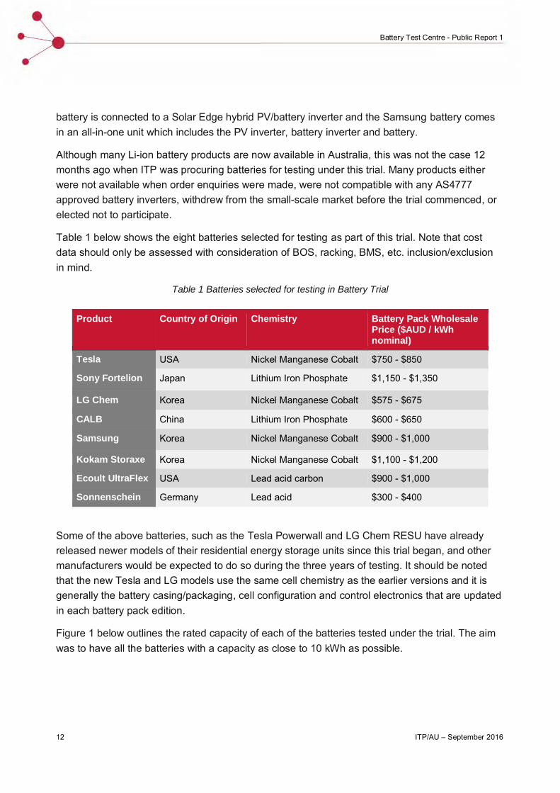
Table 1 below shows the eight batteries selected for testing as part of this trial. Note that cost data should only be assessed with consideration of BOS, racking, BMS, etc. inclusion/exclusion in mind.
Table 1 Batteries selected for testing in Battery Trial
Product Country of Origin Chemistry Battery Pack Wholesale Price ($AUD / kWh nominal)
Tesla USA Nickel Manganese Cobalt $750 - $850
Sony Fortelion Japan Lithium Iron Phosphate $1,150 - $1,350
LG Chem Korea Nickel Manganese Cobalt $575 - $675
CALB China Lithium Iron Phosphate $600 - $650
Samsung Korea Nickel Manganese Cobalt $900 - $1,000
Kokam Storaxe Korea Nickel Manganese Cobalt $1,100 - $1,200
Ecoult UltraFlex USA Lead acid carbon $900 - $1,000
Sonnenschein Germany Lead acid $300 - $400
Some of the above batteries, such as the Tesla Powerwall and LG Chem RESU have already released newer models of their residential energy storage units since this trial began, and other manufacturers would be expected to do so during the three years of testing. It should be noted that the new Tesla and LG models use the same cell chemistry as the earlier versions and it is generally the battery casing/packaging, cell configuration and control electronics that are updated in each battery pack edition.
Figure 1 below outlines the rated capacity of each of the batteries tested under the trial. The aim was to have all the batteries with a capacity as close to 10 kWh as possible.

ITP/AU – September 2016 13
Battery Test Centre - Public Report 1
Figure 1 Nominal battery capacity of each battery tested under the trial
Testing ProcedureThe key objective of the testing is to measure the batteries’ decrease in storage capacity over time and with energy throughput. As the batteries are cycled they lose the ability to store as much energy as when they are new.
To investigate this capacity fade, the lithium-ion batteries are being discharged to a state of charge (SOC) between 5% and 10% (depending on the allowable limits of the BMS), while the lead-acid batteries are being discharged to a 50% SOC (i.e. 50% of the rated capacity used). The advanced lead battery is being be cycled between 30% and 80% SOC. These operating ranges are in line with manufacturers’ recommendations for each technology.
Each battery pack is charged over several hours (mimicking daytime charging from the PV), followed by a short rest period, then discharged over a few hours (mimicking the late afternoon, early evening period) followed by another short rest period. In total, there are three charge/discharge cycles per day.
Temperature ProfileThe ITP lithium-ion battery trial aims to test batteries in ‘typical’ Australian conditions. It is expected that most residential or small commercial battery systems will be sheltered from rain and direct sunlight, but still be exposed to outdoor temperatures; therefore, the ambient temperature in the battery testing room is varied on a daily basis, and varies throughout the year. The high and low temperatures are given in Table 1.
ITP implements ‘summer’ and ‘winter’ temperature regimes for the three daily charge/discharge cycles. In the summer months the batteries undergo two cycles at the monthly high temperature

14 ITP/AU – September 2016
Battery Test Centre - Public Report 1
and the third at the monthly low temperature, and in the winter months the batteries undergo two cycles at the monthly low temperature and the third at the monthly high temperature.
Table 2: Daily high and low ambient temperatures throughout the year
Jan Feb Mar Apr May Jun Jul Aug Sep Oct Nov Dec
Low 22 20 18 16 14 12 10 12 14 16 18 20
High 36 34 32 30 28 26 24 26 28 30 32 34
Regime S S S S W W W W W W S S
Figure 2: Daily hot and cold cycle temperatures throughout the year
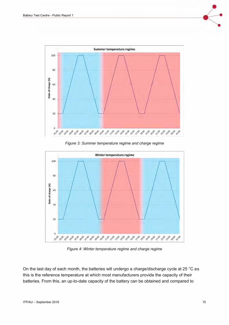
Given the focus on energy efficiency and low energy consumption at the CIT Sustainable Skills Training Hub, the timing of the high and low temperature cycles is matched with the variations of outdoor temperatures, to allow transitions between high and low temperature set-points to be assisted by outdoor air. The schedule of charge and discharge cycles is show in Figures 2 and 3.
ITP/AU – September 2016 15
Battery Test Centre - Public Report 1
Figure 3: Summer temperature regime and charge regime
Figure 4: Winter temperature regime and charge regime
On the last day of each month, the batteries will undergo a charge/discharge cycle at 25 °C as this is the reference temperature at which most manufacturers provide the capacity of their batteries. From this, an up-to-date capacity of the battery can be obtained and compared to

16 ITP/AU – September 2016
Battery Test Centre - Public Report 1
previous results to track capacity fade. Although the duration of a month varies between 28 and 31 days, this will not make a statistically relevant difference to the results.
2. IMPLEMENTATION
CALB CA100The CALB CA100 is a 3.2V, 100Ah LFP cell manufactured by the China Aviation Lithium Battery Company. CALB is a state-owned Chinese corporation that was established in 2007. CALB cells use LFP technology and are marketed as a safe, high-rate battery. 32 x CA100 cells make up the 10.24 kWh battery bank being tested in the battery trial, with an external battery management system (BMS) installed separately.
Figure 5. CALB 100 Ah, 3.2 V LFP cell
ProcurementThe Australian retailer of CALB batteries is EV Power. EV power is a Western Australia based retailer of LFP batteries and DC permanent magnet AC (PMAC) electric motors for electric vehicle conversions and energy storage applications. EV Power maintains a webstore and is easily contactable via their website (http://www.ev-power.com.au/).
EV Power had ample stock of CA100 cells used in this trial and receives frequent shipments of these batteries directly from CALB. Lead times for these batteries are typically 1 – 2 months if they are not in stock in WA. Shipping times for a pallet of CA100 batteries from WA to Canberra where the trial is hosted was approx. 1 week.
EV Power provides product support through their sales and support staff who engaged directly with ITP to help rectify integration and commissioning issues. EV Power was able to support ITP in procuring a suitable external BMS to manage and control the interaction between the battery cells and the SMA battery inverter.

ITP/AU – September 2016 17
Battery Test Centre - Public Report 1
When one of the cells in the pack at the battery trial was identified as underperforming, EV Power was able to provide a replacement cell within a reasonable period of time (~1 week from date of issue identification to new cell arriving and being installed).
The external BMS was sourced directly from REC, a global electronics manufacturer based in Slovenia. The BMS and associated components took between 3 - 4 weeks to arrive in Australia from the date the order was placed.
As REC is located in Slovenia it was difficult to get live technical support. Support was further hampered by the unique nature of the trial’s set up and communications issues with individual support technicians.
Installation
The CALB cells were simple to arrange and connect with all required components (connectors and fasteners) provided with the cells. Each cell is 3.3 kg so they were easily moved and arranged by hand, although when placed together the weight of the pack should be considered (~105 kg for 10.24 kWh) when choosing a suitable location for the battery bank. The terminals are embedded in the battery and come with protective caps for transport. This reduces the risk of DC arc between the terminals; however, once installed the cell connectors and bolts leave the terminals exposed with no insulation.
Care should be taken not to inadvertently short the terminals of any cells or the pack (with metallic tools, jewellery etc.) as the instantaneous DC current the cells can produce is significant under short circuit conditions. Shorting the terminals may also cause damage to the cells. The cells have no external protection (fusing or isolation) and as such should be treated with the same caution as PbA batteries when handling. The battery cells come without an enclosure and require some form of mounting or racking system to prevent unauthorised access and to protect the batteries from the elements.
The battery cells require external control from the BMS and as such the BMS was the component that dictated the specific pack configuration and BOS hardware required.
The Sunny Island inverter requires a battery bank voltage of 41 - 63 V. With a nominal cell voltage of 3.2 V, 16 cells were connected in series to build a nominal pack voltage of 51.2 V. There are 2 strings of 16 cells connected in parallel to the REC BMS to build the battery bank capacity to 10.24 kWh. If larger battery banks are required, multiple REC BMS’s can be connected to further banks of batteries in parallel.
The BMS monitors the voltage of each cell and protects each from over/under voltage conditions. As such the BMS needs to be electrically connected to each cell in the pack. This requires running cables between the 16 cells in the pack and the BMS. This process is quite awkward and time consuming when installing the battery.

18 ITP/AU – September 2016
Battery Test Centre - Public Report 1
The connection to the SMA inverter simply requires a CAN connection to the inverter and the positive and negative terminals of the battery to connect to the terminals of the inverter. The communications output from the REC BMS was directly compatible with the SMA inverter. The positive cable runs through a contactor, a 200 A fuse and a pre-charge controller. The contactor is controlled by the BMS, which provides the BMS with a means of disconnecting the battery from the inverter. The pre-charge controller prevents excessive inrush currents from the battery cells when initially connecting to the inverter (charging the capacitors and transformer in the inverter).
Commissioning
The most time-consuming component of commissioning was the setup of the REC BMS to manage the battery bank and communicate with the SMA inverter properly. The REC BMS software is simple to install and use, but input parameters are not clearly explained, and there is very limited documentation or technical support available to explain them. To communicate with the REC BMS it is necessary to install certain software drivers that are supplied with the BMS software package. Understanding the battery-specific parameters required by the BMS is extremely important as these values will dictate how the battery is managed. Once the BMS is correctly set up for the battery bank, communication with the inverter is taken care of by the BMS.
The only additional commissioning task is the setup of the Sunny Island inverter for the specific application, and standard electrical/operational checks or approvals before connecting the system to the loads and/or grid.
Ecoult UltraFlex
The UltraFlex’s technology is considered an advanced lead-acid technology because the negative electrode of an otherwise conventional lead-acid battery is enhanced with a carbon treatment such that the battery resembles an ultra-capacitor.
This treatment alters the lead-sulphate crystal formation during discharge, and hence alters the performance of the battery to allow it to operate at higher discharge rates, and reduce the need for a regular, full absorption charging phase, where charge acceptance and cycle efficiency is lower.
A traditional lead-acid battery requires regular full charging to avoid/reverse sulphation, but which accelerates electrode corrosion and electrolyte loss. With this innovation, the battery requires only a monthly equalisation charge, and need not be fully charged in the interim.
The battery has a BMS and individual cell monitoring to provide cell equalisation and SOC calculation when the battery operates in partial state of charge. The BMS can also automatically request the equalisation charge each month or as required.

ITP/AU – September 2016 19
Battery Test Centre - Public Report 1
The “half cabinet” installed at the battery trial provides a nominal battery bank capacity of 14.1 kWh (C10), for 7.05 kWh of usable capacity. The “full cabinet” configuration provides a storage capacity of 28.2 kWh within the same enclosure.
The UltraFlex technology was invented by Australia’s CSIRO and is now commercialised by Ecoult in Australia, Furukawa Battery Company in Japan, and East Penn Manufacturing in the US. The batteries for the UltraFlex system are manufactured in East Penn’s manufacturing plant in Pennsylvania and the BMS, software and racking is designed and made in Australia.
Figure 6 Ecoult UltraFlex cabinet, 48 V and up to 28.2 kWh capacity
ProcurementCurrently Ecoult handles all sales of its products in Australia directly. The company’s website (http://www.ecoult.com/) is where buyers can register interest in their products and find out more information about what services they offer. As the developer and manufacturer of its product, Ecoult is well qualified to handle any enquiries and is able to provide extensive technical support in Australia. Ecoult staff in Australia have been instrumental in troubleshooting any issues with the UltraFlex in the trial and providing assistance with battery installation, commissioning and monitoring.
At the time that ITP were procuring this battery (around November 2015) Ecoult were still developing the BMS and control systems around the battery technology. Consequently, ITP were able to include the UltraFlex in the trial only with an external control and monitoring system to connect to the Sunny Island inverter. Once Ecoult could provide a suitable solution for the purpose of the testing, it was able to ship the battery to ITP in a timely manner (< 1 week) given there was sufficient stock in their warehouse in Sydney.
Ecoult batteries are fully integrated/compatible with Schneider and Selectronic battery inverters and have limited compatibility with SMA and a number of other inverters.
20 ITP/AU – September 2016
Battery Test Centre - Public Report 1
Installation
The Ecoult UltraFlex cabinet is a large and heavy steel enclosure. Given the cells are lead-acid, they too are heavy, resulting in a total weight of 770 kg for the configuration at the trial (the 840 L cabinet is capable of holding up to 28.2 kWh). Being so heavy the unit is extremely difficult to move and requires some form of mechanical lifting to manoeuvre. This should be taken into account when considering this battery for certain applications. The size and weight of the unit may prevent this system from being a suitable option in some applications.
The installation of the battery was largely carried out by a team of Ecoult engineers. ITP was responsible for placing the Ecoult battery enclosure in position and running the cabling between the battery and the inverter. Positioning the battery was difficult due the significant size and weight of the system. Once the battery was in place, the cabling was relatively straightforward with the UltraFlex enclosure having a dedicated point of connection.
The Ecoult engineers who installed the battery bank were mainly focussed on installing and commissioning an independent monitoring system, which is not part of their standard product offering. This system is used by Ecoult to monitor and control (if/when necessary) its battery as it undergoes testing. Ecoult requires this monitoring and control setup as its technology is relatively new and unique in the market, and this trial constitutes one of the first and most comprehensive field tests of the technology.
Commissioning
The commissioning of the Ecoult UltraFlex was significantly delayed as the BMS installed in this particular module was not able to communicate with the SMA inverter directly. A converter inside the Ecoult monitoring system enclosure (external to the battery enclosure) was installed to act as an interface between the inverter and the BMS, but it proved to be a point of failure. This issue arose out of the product being under development at the time that ITP procured it and Ecoult not having completed the integration between the UltraFlex unit and the SMA Sunny Island inverters.
The only further commissioning that was required was the setup of the Sunny Island inverter for the specific application and standard electrical/operational checks and approvals before connecting the system to the loads/grid.
GNB Sonnenschein
Exide’s Sonnenschein Solar Block is a 6V, deep-cycle Valve Regulated Lead Acid (VRLA) gel battery. VRLA gel batteries are ubiquitous in stationary storage applications, and are the incumbent technology in the majority of RAPS systems.
The Sonnenschein brand has a strong reputation in the RAPS market and its parent company, GNB Exide Technologies, has been in the battery business for over 120 years.
ITP/AU – September 2016 21
Battery Test Centre - Public Report 1
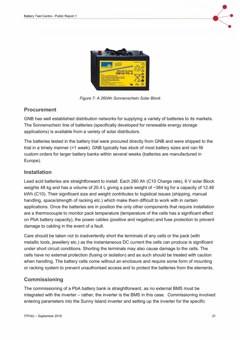
Figure 7: A 260Ah Sonnenschein Solar Block
ProcurementGNB has well established distribution networks for supplying a variety of batteries to its markets. The Sonnenschein line of batteries (specifically developed for renewable energy storage applications) is available from a variety of solar distributors.
The batteries tested in the battery trial were procured directly from GNB and were shipped to the trial in a timely manner (<1 week). GNB typically has stock of most battery sizes and can fill custom orders for larger battery banks within several weeks (batteries are manufactured in Europe).
InstallationLead acid batteries are straightforward to install. Each 260 Ah (C10 Charge rate), 6 V solar Block weights 48 kg and has a volume of 20.4 L giving a pack weight of ~384 kg for a capacity of 12.48 kWh (C10). Their significant size and weight contributes to logistical issues (shipping, manual handling, space/strength of racking etc.) which make them difficult to work with in certain applications. Once the batteries are in position the only other components that require installation are a thermocouple to monitor pack temperature (temperature of the cells has a significant effect on PbA battery capacity), the power cables (positive and negative) and fuse protection to prevent damage to cabling in the event of a fault.
Care should be taken not to inadvertently short the terminals of any cells or the pack (with metallic tools, jewellery etc.) as the instantaneous DC current the cells can produce is significant under short circuit conditions. Shorting the terminals may also cause damage to the cells. The cells have no external protection (fusing or isolation) and as such should be treated with caution when handling. The battery cells come without an enclosure and require some form of mounting or racking system to prevent unauthorised access and to protect the batteries from the elements.
CommissioningThe commissioning of a PbA battery bank is straightforward, as no external BMS must be integrated with the inverter – rather, the inverter is the BMS in this case. Commissioning involved entering parameters into the Sunny Island inverter and setting up the inverter for the specific

22 ITP/AU – September 2016
Battery Test Centre - Public Report 1
application (on grid/off grid, battery parameters etc.). Standard electrical/operational checks or approvals are then required before connecting the system to the loads and/or grid.
Kokam StoraXe
The StoraXe system is produced by German technology company ADS-TEC. ADS-TEC integrate its own BMS with Kokam lithium-ion battery cells manufactured in South Korea. The cells are 3.7V (nominal) 75Ah pouch type (Li-polymer) with an NMC cathode.
Kokam was established in 1989 and entered the battery business in 1998 after developing the polymer cell. The cell is now produced at large scales and marketed as having long life cycle life (60% available capacity after 8000 cycles @ 80% DOD) and high energy/power density (~170 Wh/kg and 2C/4C continuous charge/discharge rates). The 8.3 kWh StoraXe unit is installed in the trial.
Other common energy storage products available use Kokam battery cells including the Akasol NeoQUBE and the Sunverge SIS.
Procurement
At present, there is only one distributor of the Kokam StoraXe unit in Australia, Zest Energy. At the time of procurement, there were no StoraXe units in stock in Australia and ITP had to order directly from Germany where it is assembled. This led to a two-month delay in the arrival of the StoraXe unit to the trial site in Canberra.

ITP/AU – September 2016 23
Battery Test Centre - Public Report 1
Installation
The StoraXe unit is in an enclosure housing the battery units and the BMS. The battery system weighs 140 kg and measures 600 x 600 x 795 mm. The enclosure sits on the ground and is not able to be mounted on a wall.
The StoraXe unit requires an external power source (230 VAC 50 Hz) to supply power for the BMS and cooling fans. This power supply is hardwired into the back of the BMS module which is accessed by removing the enclosure’s top cover. The enclosure is also shipped with a small battery which is installed in the BMS module to provide it with uninterruptible power. This battery is installed in a small slot behind a panel on the front of the BMS module. This particular part of the installation is not well documented or explained in the installation manual. The battery also comes with a 200 A fuse that must be installed prior to the battery turning on. The installation of this fuse is also not well explained in the installation manual, and involves removing a panel on the front of the battery (which is only in place for transport) to connect the fuse in series with the battery leads.
The connection of the battery to the inverter involves removing the cover of the enclosure to access the battery terminals on the back of the module (the large + and – symbols on the front of the battery are not the battery terminals that the battery cables connect to). Attention should be paid to the installation manual to ensure that the polarity of the battery terminals is adhered to as it is not well labelled at the point of connection to the battery.
Commissioning
The commissioning process for the Kokam battery is complex. To set the battery up it is necessary to connect a computer to the BMS via an Ethernet cable and log into the web portal of the BMS. This process caused a lot of issues for ITP as the battery portal was difficult to access, extremely slow and often would not work at all. The supporting documentation was limited in terms of information it provided about accessing this portal and configuring the BMS. The BMS appears to have greater control over how the battery is utilised than BMS’s for other batteries. Some of these control functions are typically covered by the inverter, but in this case the BMS requires significant input about the system and how the battery will be used. Once the battery parameters are set in the BMS, communications protocols are pre-configured for SMA Sunny Island inverters.
LG Chem RESU
The RESU system is a lithium-ion battery pack & BMS, manufactured by LG Chem in South Korea. The battery uses NMC chemistry, and is available as a 6.4kWh unit, with the possibility of expansion pack connection allowing for 9.6 kWh & 12.8 kWh of total capacity. The battery is marketed as high energy density (144 Wh/L) and long life (60% available capacity after >6,000 cycles @ 90% DOD).

24 ITP/AU – September 2016
Battery Test Centre - Public Report 1
LG Chem is one of the largest lithium-ion battery manufacturers globally, and the RESU is an early market leader for lithium-ion batteries in RAPS and grid-connect systems.
LG Chem has recently released a new generation of RESU batteries that come in 3.3 kWh, 6.5 kWh and 9.8 kWh 48 V units. Two modules can be connected in parallel to build battery capacity (up to 19.6 kWh). LG Chem is also releasing a higher voltage module (~400 V) with capacities of 7 kWh and 10 kWh.
Figure 8: Generation 1 LG Chem RESU. This figure shows a 6.4 kWh unit.
ProcurementLG Chem’s RESU is one of the most commonly available lithium-ion batteries on sale in Australia, and LG Chem has well established distribution networks throughout the country. The RESU battery is available from a number of solar distributors.
LG Chem has recently established technical and battery service support in Australia through Solar Hub, a solar retailer based in the ACT. ITP purchased the LG Chem RESU battery directly from Solar Hub for this trial. Distributors generally have LG Chem batteries in stock and are able to ship to most locations across Australia within days.
Solar Hub was able to provide technical assistance with the installation of the battery and replace a faulty module immediately, indicating strong technical support networks are well established in Australia.
InstallationThe first generation RESU battery installed at the trial was simple to install. The battery sits on shelf against a wall and is attached to the wall to prevent movement. The unit is not rated for outdoor use so it must be suitably protected from exposure to the elements. The new second generation LG Chem RESU battery, which has been recently released, is wall mountable and is appropriately rated for outdoor installations.

ITP/AU – September 2016 25
Battery Test Centre - Public Report 1
The battery unit itself has two clearly labelled terminals and one communications (RJ45) port. There is also a location where the battery case can be earthed.
ITP has a single RESU 6.4 unit installed with a 3.2 kWh expansion unit included. Installation of the expansion pack involves removing small glands on the right-hand side of the main battery pack and plugging in pre-terminated cables between both packs. The expansion pack also comes with a fuse that must be inserted into the top of the module before commissioning.
The communications connection between the LG Chem battery and the SMA inverter requires a special crossover cable (shipped with the RESU battery) to translate the pin configuration on the LG Chem RESU communications port to the SMA inverter CANbus pin configuration. Without this crossover the inverter will not receive the signal from the Battery BMS allowing it to charge or discharge.
CommissioningCommissioning the LG Chem battery is quick and simple. The CAN communications are all pre-configured for the inverter. The battery has a 120A Circuit breaker on the top which must be switched on to provide power to the terminals and the fuse must be installed in the expansion pack.
Samsung SDIThe Samsung All-In-One (AIO) 10.8 is a PV and battery inverter with an internal 10.8 kWh NMC battery, manufactured by Samsung SDI in South Korea. The unit is available in 3.6/7.2/10.8 kWh capacity.
ProcurementThe Samsung All-in-one unit incorporates a PV inverter with a battery and a battery inverter to simplify the installation of the home energy generation and storage system. Samsung AIO battery units are available in Australia through various distributors. At the time of procurement there was a national freeze on the sale of the 7.2 kWh and 10.8 kWh units as there was an issue with their compliance to Australian standards. This issue has since been rectified and all units installed

26 ITP/AU – September 2016
Battery Test Centre - Public Report 1
across Australia have since been upgraded to meet Australian standards. Distributors typically have ample stock and are able to ship to most locations across Australia within days.
Samsung has partnered with AWR Group for technical support and system services throughout Australia. AWR is able to provide comprehensive support to installers and customers and has helped ITP rectify problems with integrating the Samsung system into the test facility.
Installation
As the Samsung battery is a fully integrated unit it is simple to install. The enclosure is floor-mounted, and is rated for outdoor use. The 10.8 kWh and the 7.2 kWh units have the same enclosure while the 3.6 kWh unit has a smaller enclosure; a 10.8 kWh battery unit is installed at the battery trial. The enclosure ships separately from the battery modules, so once installed the battery modules (3.2 kWh each) are fixed inside the enclosure and connected to the inverter via the internal cabling provided. The only external wiring required is the AC wiring for connection to the grid/loads and a standard PV system connection via the MC4 connectors on the side of the unit.
The installation manual provided with the AIO unit covers all aspects of the installation and commissioning process and clearly describes how each step of the installation should be undertaken. The technical support from AWR and the equipment/manuals provided with the AIO are adequate instruction for installers to install these energy storage units.
Commissioning
Commissioning the Samsung AIO can be done by directly connecting to the unit or via the web portal if an internet connection is available. The documentation on how to commission the battery is well laid out and AWR is able to provide full support with the commissioning process. This process involves the setup of the inverter for the specific application (on grid/off grid, increase self-consumption, timer operation etc.) and standard electrical/operational checks or approvals before connecting the system to the loads and/or grid. There is then a number of tests to run the system through which confirm the system is properly functioning.
Sony Fortelion
Sony was the first company to commercially produce a lithium ion cell (LCO) for portable electronics in 1991.Their LFP Fortelion cell was released in 2009. The 1.2 kWh storage and control modules are manufactured by the company in Japan and China. Storage modules incorporate LFP cells, and are designed to be mounted in standard 19” server racks. One control module is required per 16 (or fewer) storage modules. This configuration allows system designers and installers a high degree of flexibility in terms of storage capacity, with the 1.2 kWh modules allowing the battery bank capacity to be precisely tailored to meet the requirements of each user.

ITP/AU – September 2016 27
Battery Test Centre - Public Report 1
Fortelion battery technology is marketed as high power (2C), high safety, and long-lifetime (80% available capacity after 6000 cycles @ 100% DOD).
There are 8 x 1.2 kWh Sony Fortelion LFP battery modules with one BMS controller module installed at the Battery Trial giving a total installed capacity of 9.6 kWh.
ProcurementSony has the longest track record of manufacturing and selling residential Li-ion batteries of any of the manufacturers tested under this trial. Sony has well established supply chains and its batteries are easily purchased in Australia. RFI stocks Sony Fortelion modules and is able to ship them to most locations in Australia within days. RFI’s product consultants are able to provide limited technical support with the products they stock and any more detailed technical support with the Sony Fortelion units needs to be obtained through Sony directly. Unfortunately, Sony doesn’t currently have a technical support team deployed in Australia. It is necessary to order the required cables with the battery modules as the Fortelion has some specific power and communications cables that are required for the setup of the battery modules.
InstallationThe Sony Fortelion battery modules are the only server rack mounted system installed in the trial. They are sized to fit in a standard 19-inch server rack (432 mm width) taking up 2 RU of space (80 mm height) and have a depth of 421 mm. Each unit weighs approximately 17 kg so server shelves should be capable of supporting this weight.
The terminals of these batteries are on the rear of the modules. This means that access is required to the rear of the server rack as well as the front, which may hamper future maintenance. This should be considered when selecting an appropriate location for the battery bank.
All DC connections between each 1.2 kWh module and the BMS must be made by the installer. These connectors are ordered from Sony along with the battery modules as they have specific lugs that are difficult to replace with generic cable lugs. It is also important to order the correct number of connectors and the correct length for the layout of the battery bank.
The Sony modules also require specific communications cables connecting each battery to the BMS unit. Again it is important to order the correct length and quantity of these communications
28 ITP/AU – September 2016
Battery Test Centre - Public Report 1
cables and, as they have unique terminals, they must be ordered from Sony. When connecting the modules, it is necessary to assign each unit its appropriate order and connect them in the correct order according to the installation instructions.
The main terminals of the battery bank are on the back of the BMS unit; this is clearly defined in the installation manual and on the BMS itself. BMS communications to the inverter is via CANbus and is compatible with the Sunny Island inverter. The communications output of the Sony BMS is through a DB-9 serial port and needs to be connected to the RJ-45 socket in the Sunny Island. As with the LG Chem RESU, a crossover cable is required to connect the Fortelion’s communications port to the Sunny Island’s. Sony does not seem to provide an appropriate cable for this and so this cable needs to be manufactured (including pin arrangement) by the installer. This pinout configuration is not clarified in the installation manual, although Sony provides clear and comprehensive instructions for all other aspects of the installation, including the setup of the Sunny Island inverter.
Commissioning
Once installed the system is relatively straightforward to commission. It is set up for integration with Sunny Island inverters and so the only commissioning required is to set up the inverter as per the Sony instructions along with standard electrical/operational checks or approvals before connecting the system to the loads and/or grid.
Tesla Powerwall
The Tesla Powerwall is a 6.4 kWh NMC lithium-ion (NMC) battery pack and BMS, manufactured by Tesla in the USA. The Powerwall incorporates Panasonic battery cells into low voltage banks, which are then stepped up to higher voltage via a DC-DC converter.
Panasonic is one of the largest lithium-ion cell producers in the world, and the Tesla Powerwall is an early market leader for lithium-ion batteries in grid-connect systems.

ITP/AU – September 2016 29
Battery Test Centre - Public Report 1
Figure 9: The Tesla Powerwall
ProcurementThe Tesla Powerwall is one of Australia’s fastest growing energy storage products. The rapid uptake of this product in the market is largely attributed to the popularity of the Tesla brand which is synonymous with high performance EV’s. Tesla protects its reputation and brand by controlling who can install its product and ensuring those that do install it are competent and able to provide the required after-sales support. To achieve Tesla accreditation, Tesla provides its installers with training in sales, support and installation of the battery unit. As such the best contact for support with a Tesla Powerwall is the installer or Tesla directly.
At the beginning of the year when ITP was building the battery trial facilities there were only 3 companies in Australia who were accredited to supply and install Tesla Powerwall batteries. The number of accredited installers has increased since then.
Until recently the Powerwall was only compatible with one inverter, the Solar Edge Hybrid (PV and battery) inverter range. SMA has now released the Sunny Boy Storage inverter which is a battery only inverter that is compatible with the Powerwall. Fronius is also expected to bring an inverter to market imminently.
Early in the year there was limited stock of Powerwall’s as demand was high. More recently supply has caught up with demand and there are many distributors of Powerwall’s across Australia with very short lead times on shipping. Tesla is frequently releasing new models of the Powerwall (three models have been released in 2016) and making small refinements in each version. Mostly these improvements are to do with ease of installation and have little or no effect on the end user experience (the enclosure has remained the same for all models of the Powerwall).

30 ITP/AU – September 2016
Battery Test Centre - Public Report 1
In recent months, more and more installers across Australia have become accredited to install Powerwalls. Tesla has also been rapidly expanding its capabilities in Australia (and around the globe) to provide technical and sales support, as well as to develop its products further.
In October, Tesla announced the Powerwall 2, a 13.5kWh (usable) battery with an integrated inverter (5kW continuous/7kW peak), scalable up to 121.5kWh (9 x units). The systems are to be installed beginning February 2017, and the low wholesale cost of the system is likely to result in market-leading installed costs on a $/kWh basis.
Installation
The Tesla Powerwall is very large and heavy for a Li-ion NMC battery pack of 6.4kWh capacity. At almost 100 kg and with a height of 1,300 mm, 860 mm width and 180 mm depth, the Powerwall requires a large clear space and a sturdy wall to mount on. The clearances required are 300mm above and below the unit, and 100mm on each side. The Tesla Powerwall requires at least three people to lift the unit to move it or mount it onto the wall. Tesla recommends using a special trolley jack to manoeuvre the Powerwall and mount it on a wall. Most trolley jacks require a smooth flat surface up to the mounting location, which is often not available in residential installations.
Tesla also has a specific process to follow for the installation of the Powerwall which it outlines during installer training sessions. Tesla estimates that an installer’s first Powerwall installation will take around 6 hours, with installation time decreasing as installers gain experience. However, in ITP’s experience many installers find that it takes longer than this. Installing this battery is difficult and time consuming compared to other Li-ion batteries and installers should take this into account when budgeting their time for these installations. Tesla’s Powerwall 2 is expected to address these issues.
Commissioning
Once installed the Tesla Powerwall integrates easily with the Solar Edge inverter monitoring and commissioning portal. Here the installer has the ability to program how the battery is used in the specific application. Standard electrical/operational checks and approvals are required before connecting the system to the loads and/or grid.
The Tesla Powerwall must be registered online in order to receive the 10-year warranty.
Balance of System
ITP has faced a number of challenges building the battery testing facility. Many of these challenges stem from the bespoke nature of the trial.
As the trial is located in a classroom at the Canberra Institute of Technology, it is in a Class 9 building as defined by the National Construction Code (NCC). Per the NCC, any batteries over 20

ITP/AU – September 2016 31
Battery Test Centre - Public Report 1
Ah installed within a Class 9 building require a 2-hour fire rated enclosure. To comply with the Code, ITP constructed an autoclaved aerated concrete testing room within the classroom, which added considerable expense. All entries for cables or air ventilation are 2-hour fire rated, as is the door to access the room. Anecdotal evidence indicates that this requirement is not widely understood and hence is not widely adhered to.
At the time of design and construction, there were no Australian Standards or CEC guidelines for grid-connected Li-ion batteries. ITP relied upon existing standards and best practice in installing battery packs. The CEC now has installation guidelines, and Standards Australia is developing a new standard for Li-ion batteries (AS 5139), although this is unlikely come into effect until late 2017. The NCC requirements for batteries will likely still stand until they too are updated.
The control system required to operate the trial autonomously is relatively complex. ITP selected off-the-shelf controllers that have PLC functionality as well as extensive external communications and control capabilities. However, the communications link between the inverters and the control hardware has proven fragile, and highlights the difficulties in integrating 19 analog sensors, 7 binary outputs, and 8 inverters that are both sending and receiving data via two protocol conversion devices (CANbus to Modbus RTU to Modbus TCP/IP). As a result, there have been a number of unplanned communications outages during the first few months of the trial. ITP is currently custom-designing a controller that will simplify the overall architecture of the monitoring and control system.
There have also been a number of battery outages caused by the extreme conditions under which they are being tested, and the standard protection measures that were originally programmed into the inverters. Throughout the first few months of the trial ITP has adjusted the system configuration to ensure the trial outcomes are met while maintaining consistency of the testing. While results are not yet conclusive ITP expects that over the next twelve months trends will begin to appear in the different batteries’ performance.

32 ITP/AU – September 2016
Battery Test Centre - Public Report 1
3. BATTERY PERFORMANCE
Initial Issues Encountered
CALB CA100The external BMS (made by REC) used for management of the CALB battery cells allows ITP to monitor the performance of individual cells. The other batteries under trial are equipped with integrated BMS, which communicate only aggregate data to the inverters.
From the outset of the trial ITP noticed the CALB battery behaving erratically and unable to complete battery cycles. Using Infrared (IR) thermal imaging, ITP identified one cell with an elevated temperature. ITP then monitored the individual cell data and found that Cell 7 showed high internal resistance and lower capacity than all other cells in the bank. Figure 10 below shows the effects of the affected cell on the whole battery pack. Cell 7 (the blue graph) exhibits significantly different characteristics to the other cells in the pack.
Figure 10: Characteristics and effects of a high resistance/low capacity cell (Cell 7) in a battery pack
Given the data available on the cell’s performance, ITP was able to quickly obtain a replacement cell from the supplier. Once the replacement cell was installed the pack performance drastically improved.
Cell 7 Voltage drops well below other cell voltages when power is drawn from the battery
Cell 7 Voltage lower than all other cells in the pack even when full
Cell 7 reaches pack cut-off (minimum) voltage causing BMS to register battery pack as empty even though there is capacity remaining in the 15 other cells
As the pack is charged, Cell 7 voltage is brought into line with the other cells in the pack
Cell 7 has lower capacity and so prematurely reaches pack cut-off voltage (Maximum) as less energy is required to reach this voltage than for the other cells.

ITP/AU – September 2016 33
Battery Test Centre - Public Report 1
LG Chem RESUThe results show that the LG Chem RESU battery cannot maintain the power output of the testing protocol when the ambient temperature in the room is 28 °C or higher. Figure 11 below shows that the RESU consistently has a higher cell temperature than the other batteries being tested in the trial, and hence derates from time to time to protect itself from high cell temperatures. This is likely due to the following factors:
The LG Chem RESU does not utilise any form of active cooling (Kokam, Ecoult and Samsung have forced ventilation cooling while the Tesla uses a liquid cooling system);
The LG Chem RESU comes in an extremely compact and dense enclosure with a small surface area relative to its volume and mass. This is made possible by the use of prismatic stacked cells within the pack, which allow for an extremely high packing factor and therefore a compact enclosure. However, this leads to less space around the cells for heat to dissipate. By comparison, Sony uses cylindrical cells leading to spaces between the cells for heat dissipation, while CALB’s individual cells are physically separated and un-enclosed;
The internal resistance of NMC batteries is typically higher than LFP, meaning that charging and discharging the battery generates more heat;
Figure 11: Temperature of battery packs on 28th September
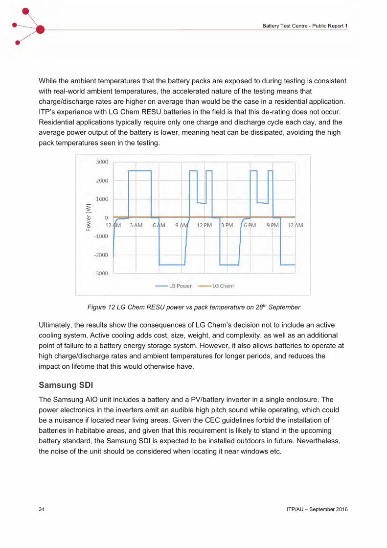
Figure 12 below shows that the LG Chem battery de-rates its power output to 800 W when the cell temperature reaches 40°C. As the ambient temperature of the room at this point is only 28°C in the data shown, more frequent de-rating is expected in the summer months to come, when the battery room temperature will be as high as 36°C.
34 ITP/AU – September 2016
Battery Test Centre - Public Report 1
While the ambient temperatures that the battery packs are exposed to during testing is consistent with real-world ambient temperatures, the accelerated nature of the testing means that charge/discharge rates are higher on average than would be the case in a residential application. ITP’s experience with LG Chem RESU batteries in the field is that this de-rating does not occur. Residential applications typically require only one charge and discharge cycle each day, and the average power output of the battery is lower, meaning heat can be dissipated, avoiding the high pack temperatures seen in the testing.
Figure 12 LG Chem RESU power vs pack temperature on 28th September
Ultimately, the results show the consequences of LG Chem’s decision not to include an active cooling system. Active cooling adds cost, size, weight, and complexity, as well as an additional point of failure to a battery energy storage system. However, it also allows batteries to operate at high charge/discharge rates and ambient temperatures for longer periods, and reduces the impact on lifetime that this would otherwise have.
Samsung SDIThe Samsung AIO unit includes a battery and a PV/battery inverter in a single enclosure. The power electronics in the inverters emit an audible high pitch sound while operating, which could be a nuisance if located near living areas. Given the CEC guidelines forbid the installation of batteries in habitable areas, and given that this requirement is likely to stand in the upcoming battery standard, the Samsung SDI is expected to be installed outdoors in future. Nevertheless, the noise of the unit should be considered when locating it near windows etc.

ITP/AU – September 2016 35
Battery Test Centre - Public Report 1
Tesla Powerwall
The Tesla Powerwall contains a buck-boost DC/DC converter which steps the battery pack voltage up to 400 V (to be compatible with the Solar Edge residential PV inverter) along with a liquid cooling system to regulate the battery temperature. No other product tested in the trial utilises liquid cooling, opting instead for forced air ventilation or no active cooling. The operation of the power electronics within the Powerwall unit and the liquid cooling pump emit an audible high pitched sound when operating. As with the Samsung AIO unit, the Powerwall’s noise should be considered when selecting the installation location.
During October, the Tesla Powerwall was offline due to a fault. The fault occurred when the battery SOC dropped below 5% during normal cycling. At this SOC, the battery disconnects from its DC/DC converter, and hence de-energises the DC bus, to ensure the SOC does not fall further, where the battery cells may be irreversibly damaged.
If the inverter was connected to a PV system (as in a standard residential installation) the PV array would re-energise the bus, allowing the battery to charge. At the test facility, however, there is no such PV array.
To rectify the issue Tesla performed a forced charge (for which the Powerwall must first be programmed to accept) to bring the Powerwall back online, and allow for cycling to recommence. Firmware was subsequently upgraded to allow the inverter to provide a small amount of charge from the grid to bring the battery out of protection mode.
Performance Data Collected
The data being collected from each battery includes:
Number of charge / discharge cycles
State of Charge of the batteries at 15 minute intervals
Routine battery test results (monthly) of usable battery capacity
Cumulative energy to / from battery banks
Battery efficiency, defined as the amount of energy extracted by a battery relative to the amount used to charge it
Temperature data
This data is published and maintained on ITP’s battery trial knowledge sharing website (http://batterytestcentre.com.au/).

36 ITP/AU – September 2016
Battery Test Centre - Public Report 1
Analysis Published
As part of ITP’s knowledge sharing commitments, detailed analysis of the data will be published every six months over the three years of the test. This milestone report constitutes the first of these six-monthly reports. Due to the short period of testing that has occurred this report focusses mainly on the findings from installing/commissioning each battery pack.
Future six monthly reports will detail testing results, with analysis of the following:
The technical performance and cost-effectiveness of each battery type/brand compared to each other and the conventional lead-acid batteries;
How actual performance compares to the manufacturers’ claims;
Why some batteries may be performing better or worse than expected and whether this may or may not be expected in real world applications; and
Lessons that can be drawn on suitability for a range of on-grid and off-grid applications.
These results aim to provide stakeholders with information on the benefits and potential drawbacks of each of the systems tested, particularly over the longer term. The target audience for these testing results includes:
Homeowners who wish to install batteries to gain further control over their energy supply;
Installers of household systems;
Electricity industry stakeholders including the electricity generators, TNSP, DNSPs, and regulators;
Overseas users similar to the above; and
Entities involved in assisting developing countries with off-grid electrification projects. These include, for example, organisations such as the World Bank, a range of Development Banks, and government aid organisations such as DFAT and its international equivalents.

ITP/AU – September 2016 37
Battery Test Centre - Public Report 1
4. LESSONS LEARNED
At this early stage of the project, the most interesting lessons have been derived from procuring, installing and commissioning the battery packs. Numerous challenges were encountered and overcome. Almost all of these challenges relate to the fact that the battery market is in its infancy and technology standardisation has yet to occur.
Market Infancy
The battery market in Australia is in a rapid development phase. Typical of many emerging technology markets, it is apparent that manufacturers are rushing to make products available in an attempt to win market share. This phase is characterised by:
Frequent model updates, which may create challenges for longer-term product support as early batteries models become obsolete (even if their underlying cell chemistry and architecture remains unchanged). This will be exacerbated by the fact that many early models will have relatively small production runs.
Market fluidity. During the development phase of the project several manufacturers withdrew previously expressed interest as they exited the small-scale end of the market.
Weak technical support. Acquiring engineering support during the both the project development and construction phases was challenging. The sales representatives of most manufacturers lacked technical knowledge, particularly in relation to how to configure their battery management systems to be compatible with our SMA battery inverters. Acquiring this advice required communicating directly with manufacturers overseas and it is apparent that most do not yet have processes in place to directly assist end-users with technical problems.
Weak Standardisation
The Australian battery market currently complicated by a wide range of products and standard approaches to a range of technical issues are yet to coalesce. Similarly, many regulatory standards are still under development. For example:
Li-ion battery voltage levels are often based on lead-acid standard voltages and in multiples of 12 volts. However, some Li-ion batteries operate at higher voltages rendering them incompatible with numerous traditional battery inverters (for example the terminals of the Tesla Powerwall operate at 350–450 volts). There is no particular need to retain the lead-acid battery standard voltages, and with proper protection, battery pack design and installation higher voltages could be both safe and efficient.

38 ITP/AU – September 2016
Battery Test Centre - Public Report 1
There are a range of ‘languages’ (communication protocols) used to allow battery management systems and inverters to communicate. During both the project development and construction phases there were several instances where complex engineering was required to translate between languages to overcome product incompatibility because each product used a different ‘language’.
The National Construction Code mandates a 2-hour fire rated enclosure for batteries above 24 V and 10 Ah. This was a consideration for the project as we were in a commercial building and had to get the enclosure certified. We found it was lower cost to have the enclosure custom-built rather than buying one off the shelf, but it was still a significant cost.


2 ITP/AU – September 2016
Title