Embed Size (px)
Citation preview

www.Fisher.com
Baumann™ 24000CVF Carbon & 24000SVFStainless Steel Flanged Control ValvesThe Baumann 24000CVF and 24000SVF line of controlvalves can be utilized for the control of pressure,temperature, level, and flow. These valves are availablewith ASME CL150 RF, CL300 RF, or PN 10-40 flangedend connections. The high performance 24000CVFand SVF designs feature low deadband and hysteresis,high flow capacity, superb control characteristics, tightshutoff and advanced packing systems tomeetdemanding service conditions. Compact and lightweight make them ideal for installation in high densitypiping systems where space is a premium.
Features Compact and light weight design reduces installedpiping costs
ASME and EN end connection options tomeet yourpiping standards
Full lift post-guided contoured plug allows flushingof debris through valve body
S31600 austenitic stainless steel trimmaterial isstandard; S41600 stainless steel trim is available
Multiple trim options are available tomeet changingprocess requirements
Epoxy powder-coated actuator with stainless steelfasteners provides corrosion resistance
Multi-spring field-reversible actuator with reduceddeadband permits direct operation from remotesignal devices
Fisherr FIELDVUEtdigital valve controller availablefor remote calibration and diagnostics in facilitiesutilizing the PlantWebt architecture
W9745-1
Baumann 24000CVF Control Valve withFIELDVUE DVC6200 Digital Valve Controller
W9746
Baumann 24000SVF Control ValvewithFIELDVUE DVC2000 Digital Valve Controller
ENVIRO-SEALt packing available for increasedpacking life and integrity
NOLEEK bellows bonnet suitable for a wide range ofoperating temperatures
Extension bonnets inmultiple lengths available forelevated temperature and cryogenic applicationservice
Product NameD103333X012
Product Bulletin52.1:24CVF_SVF
June 2012

Product NameD103333X012
Product Bulletin52.1:24CVF_SVFJune 2012
2
Figure 1. Baumann 24000CVF / SVF Control Valve Subassembly
E1245

Product NameD103333X012
Product Bulletin52.1:24CVF_SVF
June 2012
3
Table 1. Materials of ConstructionKeyNo.
Description Material
1Valve Body, Carbon Steel Cast Carbon Steel (Dual Certified ASTMA216WCC/GP240GHWN1.0619)
Valve Body, Stainless Steel ASTMA351 CF3M
2Seat Ring (For Low Flow Trim, Refer
to tables 2 & 3)Standard ASTMA276 S31600 Condition A /Optional ASTM A582 S41600 Condition T
4
Plug (Metal Seat) Cv < 2.5Standard ASTMA479 S21800 Annealed/Optional ASTM A582 S41600 Condition T
Plug (Metal Seat) Cv > 4.0Standard ASTM A276 S31600 Condition A/Optional ASTM A582 S41600 Condition T
Plug (Soft Seat) ASTMA276 S31600 Condition Awith PTFE (Polytetrafluoroethylene) Insert
5 Stem ASTM A276 S31600 Condition A
8
Bonnet, Carbon Steel (Std) Cast Carbon Steel (ASTM A216 GradeWCC/GP240GHWN1.0619)
Bonnet, Stainless Steel (Std) ASTMA351 CF3M
Bonnet (extended)(1) ASTM A351 CF3M& ASTM A479 S31600/S31603, Annealed
Bonnet (NOLEEK)(1) ASTM A351 CF3M& ASTM A479 S31600/S31603, Annealed
8a Bonnet Bushing(2) ASTMA276 S44004, HT 56-60 HRC
9 Drive Nut (Yoke) S31600 (ASTM A194 Grade 8M)
10 Packing Follower ASTM A276 S31600 Condition A
11 Stud S30400 (ASTMA193 Grade B8, Class 1)
12 Nut S31600 (ASTM A194 Grade B8M)
14V-Ring Packing (standard) Refer to figure 4, table 4
Packing (optional) Refer to figures 5 & 6, tables 5 & 6
27 Locknuts Stainless Steel (18-8 SST)
49 Body Gasket Graphite Grade GHRwith S31600 Insert
58 Travel Indicator ASTM A240 S304001. Extension bonnets and NOLEEK bellows bonnets are available with 24000SVF stainless steel valves only.2. Guide bushing is applicable to 24000CFV carbon steel valve assembly only.

Product NameD103333X012
Product Bulletin52.1:24CVF_SVFJune 2012
4
Figure 2. Optional 151 Low Flow Trim Assembly
E1246
151 Low Flow TrimAssemblyThe PTFE seat surrounds the valve plug (key 4) toeliminate clearance flow typical of lapped-inmetal-to-metal close clearancemicro trims. Flow isdirected over the valve plug and forced through asingle V-notch path as the plugmoves above the PTFEseat providing precise and predictable control over itsentire travel range. When the V-notchmoves belowthe PTFE seat, CLVI primary shutoff is achieved.
A live-loadedmetal collar fully retains the PTFE seat.The valve plug (key 4) seats against themetal collarproviding CL IV secondary shutoff. In addition, the fluidprocess pressure combines with the actuator seatingforce to form a hydraulic seal within the fully retainedPTFE seat. Therefore, the higher the process pressurethe tighter the shutoff.
Figure 3. Optional 151 Low Flow Trim Assembly
E1247
Table 2. 151 Low Flow TrimKey No. Description Material
2(1) Seat Ring ASTMA276 S31600 Condition A
4(1) Plug ASTMA479 S21800
Seat Subassembly
51(1)
Cage ASTMA276 S31600
Seat PTFE
Collar ASTMA276 S31600
Washer ASTMA276 S31600
Insert ASTMA276 S316001. For optional trimmaterials, consult your Emerson Process Management sales officefor price and delivery.
Table 3. 177 Low Flow TrimKey No. Description Material
2(1) Seat Ring ASTM A276 S31600 Condition A
Seat Subassembly
2a(1)
23 Gland ASTM A276 S31600
24 Retainer Nut ASTM A276 S31600
25 Insert Reinforced PTFE
26 Housing ASTM A276 S31600
4(1) Plug ASTM A479 S218001. For optional trimmaterials, consult your Emerson Process Management sales officefor price and delivery. Baumann 32 actuator requires duel-stops with 177 trim series.

Product NameD103333X012
Product Bulletin52.1:24CVF_SVF
June 2012
5
Figure 4. Standard Spring-Loaded PTFE V-RingPacking Kit
E1240
Table 4. Standard Spring-Loaded PTFE V-RingPacking KitKey No. Description Material
6 Spring ASTM A313 S30200
14 Packing SetPTFE (Polytetrafluoroethylene) / PTFE,
25% carbon filled
16 Washer ASTM A240 S31600
20 Spacer J-2000 (filled PTFE)
Figure 5. Molded Graphite (Flexible Graphite)Packing Kit (Optional)
E1241
Table 5. Molded Graphite (Flexible Graphite) PackingKit (Optional)Key No. Description Material
13 Bushings Carbon - Graphite
14A Packing Rings Graphite
14B Packing Ring Graphite
Figure 6. ENVIRO-SEAL Packing Kit (Optional)
E1248
Table 6. ENVIRO-SEAL Packing Kit (Optional)Key No. Description Material
13 Bushings Carbon Graphite
14 Packing SetPTFE (Polytetrafluoroethylene) / PTFE,
25% carbon filled
17 Belleville Spring ASTM B637 N07718, 40 HRCMax
18 Bushing PEEK (Polyetheretherketone)
19 Washer Modified PTFE
Special ENVIRO-SEALPacking NoteThe ENVIRO-SEAL PTFE packing system is suitable for100 ppm environmental applications on services up to51.7 barg (750 psig) and process temperaturesranging from -46 to 232_C (-50 to 450_F).
For non-environmental applications, this packingsystem offers excellent performance at the sametemperature range up to themaximum valve workingpressure.
Temperature limits apply to packing arrangementsonly. Complete valve assembly temperature limits maydiffer. Refer to appropriate pressure/ temperatureratings.
Reference Fisher Packing Selection Guidelines forSliding-Stem Valves, bulletin 59.1:062, D101986X012.

Product NameD103333X012
Product Bulletin52.1:24CVF_SVFJune 2012
6
WARNING
The Baumann NOLEEK valve bonnet assembly is notintended for use in lethal service applications.
The NOLEEK Bellows Bonnet Assembly is reliable anduser-friendly. Typical service life is in excess of 250,000full cycles under 100 psi pressure. The bonnet addsonly approximately 5 inches to the height of astandard valve. Operating temperature range is -195to 399_C (-320 to 750_F).
ONLY AVAILABLEWITH 24000SVF STAINLESS STEELVALVES.
Figure 7. Baumann NOLEEK Bellow Bonnet Assembly
E1249
TIME PROVENDOUBLEWALLEDBELLOWMADEFROM S31600,RATED FORUP TO49.7 BAR (720 PSI)PRESSURE
UNLIMITED STEMROTATIONWITHOUTTWISTING BELLOWS
BACKUP PACKINGSYSTEM (SEE PACKINGDETAIL ON PAGE 5)
TELL-TALECONNECTION(1/8 NPT)
BELLOWSHOUSINGFull extension providesheat dissipation, idealfor heat transfer fluids.
Table 7. Baumann NOLEEK Bellow Bonnet AssemblyKey Number Description Material
4 Plug Refer to table 1
8 Bellows Bonnet Sub-Assembly
Housing S31600/S31603
Bellows S31603/1.4571 SST
Bonnet CF3M
21 Plug Retaining Pin S30300
22 Hex Socket Pipe Plug, 1/8 NPT S30400
Figure 8. Bellows Pressure / Temperature Curve
TEMPERATURE (_F)

Product NameD103333X012
Product Bulletin52.1:24CVF_SVF
June 2012
7
Table 8. Cv Values at 100% Plug Opening (Kv = 0.86 x Cv)
VALVE SIZEORIFICEDIAMETER
PLUGTRAVEL
PLUG SERIES
102 151 177 577 548 / 588 677 648 / 688
NPS inch inch Cv Cv Cv Cv Cv Cv Cv
1/23/41
0.156 0.50 ---
0.000130.000250.00050.0010.0020.0040.0080.0150.030.060.100.200.45
--- --- --- --- ---
0.25 0.500.02, 0.050.10, 0.20
--- --- ---0.22, 0.611.0
---0.51.0
0.3125 0.50 --- ---
0.00050.001, 0.0020.005, 0.010.02, 0.05
--- --- --- ---
0.375 0.50 --- --- --- 1.0, 1.5 2.5 1.5 2.50.1, 0.2, 0.51.0, 2.5
1.52.5
1/2 0.8125 0.50 --- --- --- 4, 6 4.7, 6.7 5 4, 6
3/4 0.8125 0.50 --- --- --- 4, 7.5 4.7, 10 5 4, 8
10.8125 0.50 --- --- --- 4, 8.5 4.7, 10 5 4, 9
1.0625 0.50 --- --- --- 13 15.5 --- 13
1-1/21.25 0.75 --- --- --- 20 10, 20 20 10, 20
1.5 0.75 --- --- --- 10, 17, 28 10, 17, 32.7 10, 17 10, 17, 28
21.5 0.75 --- --- --- 10, 17, 28 10, 17, 32.7 10, 17 10, 17, 28
2.0 0.75 --- --- --- 30 53.7 30, 50 30, 50
Figure 9. Baumann 24000CVF / SVF Trims
W9747 W9751 W9748 W9749 W9750
102 LinearLow Flow Trim
151Modified Equal %Low Flow Trim
177Modified Equal %Low Flow Trim
548 / 577 / 588Equal % Trim
648 / 677 / 688Linear Trim

Product NameD103333X012
Product Bulletin52.1:24CVF_SVFJune 2012
8
Table 9. ISA Sizing CoefficientsSeries Cv Rating FL Fd XT KC
102
0.020.050.100.20
0.95
0.060.090.0130.18
0.76 0.86
151
0.000130.000250.00050.0010.0020.0040.0080.0150.030.060.100.200.45
0.98
0.350.040.050.060.0750.10.110.150.180.220.250.30.4
0.81 0.94
177
0.00050.0010.0020.0050.010.020.05
0.95 0.7 0.76 0.86
577
11.52.5467.58.5101317202830
0.9
0.400.330.42
0.68 0.73
0.46
548/588
0.220.6111.52.54.76.71015.5201732.753.7
0.98 0.28 0.81 0.94
0.9
0.40.330.46
0.68 0.730.46

Product NameD103333X012
Product Bulletin52.1:24CVF_SVF
June 2012
9
Table 9. ISA Sizing Coefficients (continued)Series Cv Rating FL Fd XT KC
677
0.10.20.512.551017203050
0.9
0.080.120.190.27
0.68 0.73
0.46
648/688
0.511.52.54689101320283050
0.9
0.40.330.42
0.68 0.73
0.46
Table 10. Technical SpecificationsVALVE TYPE EN ASME
NOMINAL PIPE SIZE DN 15, 20, 25, 40, & 50 NPS 1/2, 3/4, 1, 1-1/2, & 2
END CONNECTIONS PN 10-40 Flanges per EN 1092-1CL150 RF or CL300 RF Flanges per
ASME B16.5
PRESSURE RATING PN 40 per EN 1092-1 CL150 or CL300 per ASME B16.34
FACE-TO-FACE DIMENSIONS Consistent with EN 558-1 Consistent with EN 588-2 (ISA S75.03)

Product NameD103333X012
Product Bulletin52.1:24CVF_SVFJune 2012
10
Table 11. Temperature Ratings for Packing and Seat Material(1)
SEATINGMATERIAL
PTFE Soft Seat151 Trim -29 to 177_C (-20 to 350_F)
577 & 677 Trim -73 to 232_C (-100 to 450_F)
Reinforced PTFE 177 Trim -73 to 232_C (-100 to 450_F)
Metal Seat 102, 548, 588, 648, 688 Trim -195 to 537_C (-320 to 1000_F)
PACKING AND BONNETCOMBINATIONS
BONNET STYLE PACKING TEMPERATURE LIMIT
Standard Bonnet
Spring Loaded PTFE -73 to 232_C (-100 to 450_F)
ENVIRO-SEAL -46 to 232_C (-50 to 450_F)
Graphite -73 to 232_C (-100 to 450_F)
Extension Bonnet(2, 3)Spring Loaded PTFE -195 to 232_C (-320 to 450_F)
ENVIRO-SEAL -46 to 232_C (-50 to 450_F)
Graphite -195 to 537_C (-320 to 1000_F)
Bellows(2) NOLEEK Bellows -195 to 399_C (-320 to 750_F)
CHARACTERISTIC Equal Percentage or Linear1. Temperature limits apply to seating or packing arrangements only. Complete valve assembly temperature limits may differ, refer to appropriate pressure/temperature ratings. Formore information on packing selection, reference Fisher Packing Selection Guidelines for Sliding-Stem Valves, Bulletin 59.1:062 (D101986X012).2. Extension bonnets and NOLEEK bellows bonnets are applicable for the 24000SVF stainless steel body assembly ONLY.3. PTFE packing can be used in cryogenic service but becomes stiff.
Table 12. Actuator SpecificationsTYPE 32, 54, 70Multi-Spring Diaphragm (Single Acting)
DIAPHRAGMAREA 210, 350, 450 cm2 / 32, 54, 70 in2
AIR FAILURE 32 and 54 Fails Open or Closed (Field Reversible) / 70 Fails Closed ONLY
TRAVEL 12.7 or 19.1 mm / 0.50 or 0.75 inches
AMBIENT TEMPERATURE RANGE -29_C to 71_C / -20_F to 160_F
MAXIMUMAIR PRESSURE 2.4 barg / 35 psig
DIAPHRAGMMATERIAL(1) NBR (Nitrile) / TPES (Polyester Thermoplastic)
SPRING CASES Steel, Powder Epoxy-Coated with Stainless Steel Fasteners
YOKE Ductile Iron, Powder Epoxy-Coated1. Optional reinforced VMQ (Silicone) diaphragmwith FKM (Fluorocarbon) O-ring actuator stem seal for high temperature conditions (-29_C to 121_C / -20_F to 250_F) is available withBaumann 32 and 54 actuators ONLY.

Product NameD103333X012
Product Bulletin52.1:24CVF_SVF
June 2012
11
Figure 10. Baumann 24000CVF Carbon Steel Flanges, Pressure-Temperature Ratings
E1251-1
E1252-1
ASME B16.34 A216 WCC
Class 150
260 psig @ 200°F
750 psig @ 200°F750 psig @ -20°F
Class 300
685 psig @ 450°F
290 psig @ -20°F
185 psig @ 450°F
0
100
200
300
400
500
600
700
800
900
-50 0 50 100 150 200 250 300 350 400 450 500
Temperature (°F)
Pre
ss
ure
(p
sig
)
ASME B16.34 A216 WCC
Class 150
17.7 barg @ 100°C
51.5 barg @ 100°C51.7 barg @ -29°C
Class 300
47.1 barg @ 232°C
19.8 barg @ -29°C
12.7 barg @ 232°C
0
10
20
30
40
50
60
-50 0 50 100 150 200 250
Temperature (°C)
Pre
ssu
re (
bar
g)

Product NameD103333X012
Product Bulletin52.1:24CVF_SVFJune 2012
12
Figure 11. Baumann 24000SVF Stainless Steel Flanges, Pressure-Temperature Ratings
E1254-1
E1255-1
ASME B16.34 A351 CF3M
Class 150
275 psig @ -320 F
140 psig @ 600 F
20 psig @ 1000 F
Class 300
720 psig @ -320°F
450 psig @ 600°F
365 psig @ 1000°F
0
100
200
300
400
500
600
700
800
-400 -300 -200 -100 0 100 200 300 400 500 600 700 800 900 1000 1100
Temperature (°F)
Pre
ssu
re (
psi
g)
ASME B16.34 A351 Gr. CF3M
19 barg @ -195°C
25.2 barg @ 538°C
1.4 barg @ 538°C
10.2 barg @ 300°C
Class 300
Class 150
49.6 barg @ -195°C
31.6 barg @ 300°C
0
10
20
30
40
50
60
-250 -200 -150 -100 -50 0 50 100 150 200 250 300 350 400 450 500 550 600
Temperature (°C)
Pre
ssu
re (
bar
g)

Product NameD103333X012
Product Bulletin52.1:24CVF_SVF
June 2012
13
Figure 12. Baumann 24000CVF and 24000SVF Pressure-Temperature Ratings for EN 1092-1
E1256-1
E1253-1
24000SVF
24000CVF
EN1092-1 ASTM A216 WCC
40 barg @ 0°C
PN 40
0
5
10
15
20
25
30
35
40
45
-50 0 50 100 150 200 250
Temperature (°C)
Wo
rkin
g P
ress
ure
(b
arg
)
31.4 barg @ 232°C
EN 1092-1 ASTM A351 CF3M
24.3 barg @ 500°C
PN 40
40 barg @ 0°C
0
5
10
15
20
25
30
35
40
45
-50 50 150 250 350 450 550
Temperature (°C)
Wo
rkin
g P
ress
ure
(b
arg
)

Product NameD103333X012
Product Bulletin52.1:24CVF_SVFJune 2012
14
Table 13. Allowable Pressure Drops (bar). Do not exceed valve body temperature pressure ratings.
ORIFICEDIA.(mm)
PLUGTRAVEL(mm)
ACTTYPE
AIR-TO-OPEN ACTION AIR-TO-CLOSE ACTION
BENCHRANGE(barg)
0.2-1.0 barg SIGNALTO ACTUATOR
WITH POSITIONER1.38 barg AIRSUPPLY BENCH
RANGE(barg)
0.2-1.0 barg SIGNALTO ACTUATOR
WITH POSITIONER1.38 barg AIRSUPPLY
Max CLIV
ShutoffPress.
Max CLVI
ShutoffPress.
Max CLIV
ShutoffPress.
Max CLVI
ShutoffPress.
Max CLIV
ShutoffPress.
Max CLVI
ShutoffPress.
Max CLIV
ShutoffPress.
Max CLVI
ShutoffPress.
4.0 12.7 32 0.3-1.0 51.7 --- 51.7(1) --- 0.2-0.9 51.7 --- 51.7(1)(2) ---
6.3 12.7 32 0.3-1.0 51.7 --- 51.7(1) --- 0.2-0.9 51.7 --- 51.7(1)(2) ---
7.9 12.7 32 0.3-1.0 --- 28.8 --- 51.7(1)(2) 0.2-0.9 --- 28.8 --- 51.7(1)(2)
9.5 12.7 32 0.3-1.0 31.2 19.2 51.7(1) 50.3 0.2-0.9 31.2 19.2 51.7(1)(2) 51.7(1)
20.6 12.7
32 0.3-1.0 7.79 1.31 15.6 9.10 0.2-0.9 7.79 1.31 27.3 20.8
32 0.5-1.0 15.6 9.10 23.4 16.9 0.2-0.7 19.5 13.0 39.0 32.5
54 0.3-1.0 5.93 --- 17.7 11.2 0.2-0.9 11.8 5.30 41.4 34.8
54 0.5-1.0 23.6 17.0 35.4 28.9 0.2-0.7 29.5 23.0 51.7(1) 51.7(1)
54 0.6-1.0 35.4 28.9 47.2 40.7 --- --- --- --- ---
27.0 12.7
32 0.3-1.0 4.19 --- 9.45 4.27 0.2-0.9 4.69 --- 16.5 11.4
32 0.5-1.0 9.45 4.27 14.1 8.96 0.2-0.7 11.8 6.62 23.6 18.4
54 0.3-1.0 3.59 --- 10.7 12.5 0.2-0.9 7.17 2.0 25.0 19.9
54 0.5-1.0 14.3 9.10 21.4 16.3 0.2-0.7 17.9 12.7 35.7 30.5
54 0.6-1.0 21.4 16.3 28.5 23.4 --- --- --- --- ---
31.8 19.1
32 0.3-1.0 3.45 --- 6.96 2.48 0.2-0.9 3.45 --- 12.1 7.65
32 --- --- --- --- --- 0.2-0.7 8.69 4.20 17.3 12.9
54 0.3-1.0 5.24 --- 10.5 6.07 0.2-0.9 5.24 --- 18.3 13.9
54 0.5-0.9 10.9 6.07 15.7 11.3 0.2-0.7 13.1 8.69 26.3 21.8
54 0.7-1.0 18.3 13.9 23.6 19.2 --- --- --- --- ---
70 0.7-1.0 24.9 20.5 32.1 27.6 --- --- --- --- ---
38.1 19.1
32 0.3-1.0 2.14 --- 4.89 1.10 0.2-0.9 2.41 --- 8.55 4.76
32 --- --- --- --- --- 0.2-0.7 6.13 2.34 12.2 8.48
54 0.3-1.0 3.72 --- 7.38 3.65 0.2-0.9 3.72 --- 19.9 9.17
54 0.5-0.9 7.38 3.65 11.1 7.31 0.2-0.7 9.24 5.52 18.5 14.8
54 0.7-1.0 12.9 9.17 16.7 12.9 --- --- --- --- ---
70 0.7-1.0 17.7 13.9 22.7 18.9 --- --- --- --- ---
70 0.8-1.2 --- --- 27.7 23.9 --- --- --- --- ---
50.8 19.1
32 0.3-1.0 1.38 --- 2.83 --- 0.2-0.9 1.38 --- 4.89 2.0
32 --- --- --- --- --- 0.2-0.7 3.52 --- 7.03 4.14
54 0.3-1.0 2.14 --- 4.27 1.38 0.2-0.9 2.14 --- 7.44 4.55
54 0.5-0.9 4.27 1.38 6.34 3.52 0.2-0.7 5.31 2.41 10.6 7.72
54 0.7-1.0 7.45 4.55 9.58 6.69 --- --- --- --- ---
70 0.7-1.0 10.1 7.24 13.0 8.07 --- --- --- --- ---
70 0.8-1.2 --- --- 15.9 13.0 --- --- --- --- ---
1. Themaximum shutoff pressure when using ENVIRO-SEAL packing is defined by:nP = Table Value - [1112(Port Diameter)2]. These table values should not bemodified by this formula andthemaximumnP of 51.7 bar should be used for ENVIRO-SEAL packing.2. Themaximum shutoff pressure when using Flexible Graphite packing is defined by:nP = Table Value - [5337(Port Diameter)2]. These table values should not bemodified by this formula andthemaximumnP of 51.7 bar should be used for Flexible Graphite packing.

Product NameD103333X012
Product Bulletin52.1:24CVF_SVF
June 2012
15
Table 14. Allowable Pressure Drops (psi). Do not exceed valve body temperature pressure ratings.
ORIFICEDIA. (in)
PLUGTRAVEL(in)
ACTTYPE
AIR-TO-OPEN ACTION AIR-TO-CLOSE ACTION
BENCHRANGE(psig)
3-15 psig SIGNAL TOACTUATOR
WITH POSITIONER20 psig AIR SUPPLY
BENCHRANGE(psig)
3-15 psig SIGNAL TOACTUATOR
WITH POSITIONER20 psig AIR SUPPLY
Max CLIV
ShutoffPress.
Max CLVI
ShutoffPress.
Max CLIV
ShutoffPress.
Max CLVI
ShutoffPress.
Max CLIV
ShutoffPress.
Max CLVI
ShutoffPress.
Max CLIV
ShutoffPress.
Max CLVI
ShutoffPress.
0.156 0.50 32 5-15 750 --- 750(1) --- 3-13 750 --- 750(1)(2) ---
0.25 0.50 32 5-15 750 --- 750(1) --- 3-13 750 --- 750(1)(2) ---
0.3125 0.50 32 5-15 --- 418 --- 750(1)(2) 3-13 --- 418 --- 750(1)(2)
0.375 0.50 32 5-15 452 278 750(1) 730 3-13 452 278 750(1)(2) 750(1)
0.8125 0.50
32 5-15 113 19 226 132 3-13 113 19 396 301
32 7-15 226 132 339 245 3-10 283 188 565 471
54 4-15 86 --- 257 162 3-13 171 77 600 505
54 7-15 343 248 514 419 3-10 428 334 750(1) 750(1)
54 9-15 514 419 685 591 --- --- --- --- ---
1.0625 0.50
32 5-15 68 --- 137 62 3-13 68 --- 239 165
32 7-15 137 62 205 130 3-10 171 96 342 267
54 4-15 52 --- 155 81 3-13 104 29 363 288
54 7-15 207 132 311 236 3-10 259 184 518 443
54 9-15 311 236 414 340 --- --- --- --- ---
1.25 0.75
32 5-15 50 --- 101 36 3-13 50 --- 176 111
32 --- --- --- --- --- 3-10 126 61 251 187
54 5-15 76 --- 152 88 3-13 76 --- 266 202
54 7-13 152 88 228 164 3-10 190 126 381 316
54 10-14 266 202 343 278 --- --- --- --- ---
70 10-15 362 297 466 401 --- --- --- --- ---
1.5 0.75
32 5-15 35 --- 71 16 3-13 35 --- 124 69
32 --- --- --- --- --- 3-10 89 34 177 123
54 5-15 54 --- 107 53 3-13 54 --- 188 133
54 7-13 107 53 161 106 3-10 134 80 269 214
54 10-14 188 133 242 187 --- --- --- --- ---
70 10-15 256 201 329 274 --- --- --- --- ---
70 12-18 --- --- 402 347 --- --- --- --- ---
2.0 0.75
32 5-15 20 --- 41 --- 3-13 20 --- 71 29
32 --- --- --- --- --- 3-10 51 --- 102 60
54 5-15 31 --- 62 20 3-13 31 --- 108 66
54 7-13 62 20 92 51 3-10 77 35 154 112
54 10-14 108 66 139 97 --- --- --- --- ---
70 10-15 147 105 189 147 --- --- --- --- ---
70 12-18 --- --- 230 189 --- --- --- --- ---
1. Themaximum shutoff pressure when using ENVIRO-SEAL packing is defined by:nP = Table Value - [25(Port Diameter)2]. These table values should not bemodified by this formula and themaximumnP of 750 psi should be used for ENVIRO-SEAL packing.2. Themaximum shutoff pressure when using Flexible Graphite packing is defined by:nP = Table Value - [120(Port Diameter)2]. These table values should not bemodified by this formula andthemaximumnP of 750 psi should be used for Flexible Graphite packing.

Product NameD103333X012
Product Bulletin52.1:24CVF_SVFJune 2012
16
Figure 13. Dimensional Drawings
NOTE: ACTUATOR REMOVAL REQUIRES 115mm (4.5 INCHES) VERTICAL CLEARANCE.
216(48.5)
279(411.0)
333(413.1)
216(48.50)
160(46.3)
160(46.3)
94(3.7)
141(5.5) 127 (5.0)
276(10.9)
60(2.4)
271(10.7)
229(9.0)
3/4 INCHSQUARE
31 (1.24)
163 (6.4)MAX
130(5.1)MAX
E1257
227(8.9)
72(2.8)
24000CVF/SVF FLANGEDWITH BAUMANN 32 ATO
ACTUATORWITHHANDWHEEL
BAUMANN 54 ATO ACTUATORWITH HANDWHEEL ANDDVC2000
BAUMANN 70 ATOACTUATORWITH OPTIONALFIELDVUE DIGITAL VALVE
CONTROLLER
BAUMANN 32 ACTUATORWITH ADJUSTABLE
OPEN / CLOSE DUAL TRAVELSTOPS
BAUMANN 32 ATC / FAILOPEN ACTUATORWITH
HANDWHEEL
BAUMANN 54 ATC / FAILOPEN ACTUATORWITH
HANDWHEEL
mm(inch)
Table 15. Valve AssemblyWeightsVALVE SIZE 24000CVFWEIGHTS 24000SVFWEIGHTS
ACTUATORWEIGHTSEN ASME CL150 CL300 EN 10-40 CL150 CL300 EN 10-40
DN NPS kg lb kg lb kg lb kg lb kg lb kg lb TYPE kg lb
15 1/2 3.1 6.8 3.3 8.3 3.8 7.7 3.7 7.2 3.5 8.2 3.5 7.8 32 4.5 10
20 3/4 3.3 7.3 3.4 10 4.5 9.2 4.7 7.4 4.2 10.3 4.3 9.4 54 11.3 25
25 1 4.8 10.6 5.1 13.8 6.3 12.6 6.4 11.2 5.7 14 5.9 13 70 15.4 34
40 1-1/2 8.3 18.2 8.3 24.8 11.3 21.2 11.4 18.3 9.6 25.2 9.8 21.7
50 2 14.1 31 13.8 35.3 16 33.4 16.1 30.4 15.2 35.4 15.2 33.4
Product NameD103333X012
Product Bulletin52.1:24CVF_SVF
June 2012
17
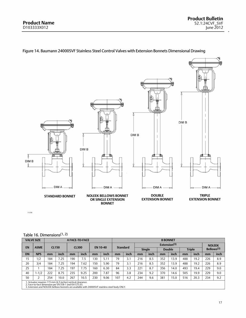
Figure 14. Baumann 24000SVF Stainless Steel Control Valves with Extension Bonnets Dimensional Drawing
E1258
STANDARD BONNET NOLEEK BELLOWS BONNETOR SINGLE EXTENSION
BONNET
DOUBLEEXTENSION BONNET
TRIPLEEXTENSION BONNET
Table 16. Dimensions(1, 2)
VALVE SIZE A FACE-TO-FACE B BONNET
EN ASME CL150 CL300 EN 10-40 StandardExtension(3) NOLEEK
Bellows(3)Single Double Triple
DN NPS mm inch mm inch mm inch mm inch mm inch mm inch mm inch mm inch
15 1/2 184 7.25 190 7.5 130 5.11 79 3.1 216 8.5 352 13.9 488 19.2 226 8.9
20 3/4 184 7.25 194 7.62 150 5.90 79 3.1 216 8.5 352 13.9 488 19.2 226 8.9
25 1 184 7.25 197 7.75 160 6.30 84 3.3 221 8.7 356 14.0 493 19.4 229 9.0
40 1-1/2 222 8.75 235 9.25 200 7.87 96 3.8 234 9.2 370 14.6 505 19.9 229 9.0
50 2 254 10.0 267 10.5 230 9.06 107 4.2 244 9.6 381 15.0 516 20.3 234 9.21. Actuator requires 115mm (4.5 inches) vertical clearance.2. Face-to-face dimension per EN 558-1 and ISA S75.03.3. Extension and NOLEEK bellows bonnets are available with 24000SVF stainless steel body ONLY.

Product NameD103333X012
Product Bulletin52.1:24CVF_SVFJune 2012
18
Table 17. Model Numbering System24
ActuatorType
Valve Body Plug Series Characteristic SeatLeakage
Valve BodyMaterial Bonnet Style
32(1) 102 Linear / Metal Seat IV CVF Carbon Omit Standard
54 151 Modified Equal % / PTFE Seat VI SVFStainlessSteel
E Extended(3)
70 177 Modified Equal % / Reinforced PTFE VI EB Bellows(3)
MV1020(2) 548 Equal % / Metal Seat (S41600) IV
VA1020(2) 577 Equal % / PTFE Seat VI
588 Equal % / Metal Seat (S31600) IV
648 Linear / Metal Seat (S41600) IV
677 Linear / PTFE Seat VI
688 Linear / Metal Seat (S31600) IV1. Baumann 32 actuator requires dual stops with 177 trim series.2. Refer to bulletin 52.1:ECV, Baumann Electronic Modulating Actuators, D103347X012, for details on these electronic actuators.3. Only available with 24000SVF stainless steel valve bodies.

Product NameD103333X012
Product Bulletin52.1:24CVF_SVF
June 2012
19

Product NameD103333X012
Product Bulletin52.1:24CVF_SVFJune 2012
20
Emerson Process ManagementMarshalltown, Iowa 50158 USASorocaba, 18087 BrazilChatham, Kent ME4 4QZUKDubai, United Arab EmiratesSingapore 128461 Singapore
www.Fisher.com
The contents of this publication are presented for informational purposes only, and while every effort has beenmade to ensure their accuracy, they are notto be construed as warranties or guarantees, express or implied, regarding the products or services described herein or their use or applicability. All sales aregoverned by our terms and conditions, which are available upon request. We reserve the right tomodify or improve the designs or specifications of suchproducts at any time without notice.
E 2009, 2012 Fisher Controls International LLC. All rights reserved.
Baumann, Fisher, FIELDVUE, PlantWeb, and ENVIRO-SEAL aremarks owned by one of the companies in the Emerson Process Management business unit ofEmerson Electric Co. Emerson Process Management, Emerson, and the Emerson logo are trademarks and servicemarks of Emerson Electric Co. All othermarks are the property of their respective owners.
Neither Emerson, Emerson Process Management, nor any of their affiliated entities assumes responsibility for the selection, use or maintenanceof any product. Responsibility for proper selection, use, andmaintenance of any product remains solely with the purchaser and end user.


![Igorlied [de Baumann]](https://img.pdfslide.net/doc/110x75/563db8b5550346aa9a963434/igorlied-de-baumann.jpg)