Embed Size (px)
Citation preview
Bay Control IED
2
GR-200 series - The GR-200 Series is Toshiba’s next generation of protection and control IED’s, designed for transmission/distribution networks and providing a platform for distributed and renewable energy systems and railway applications. Flexible adaptation is enabled using extensive hardware and modular software combinations facilitating an application oriented solution.
Meeting your needs - Extensive hardware and modular software combinations provide the flexibility to meet your application and engineering requirements. Future upgrade paths and minor modifications are readily achievable on demand.
Powerful and wide application - In addition to protection & control, GR-200 has been designed to meet the challenges and take advantage of developments in information & communications technology.
AAPPPPLLIICCAATTIIOONN
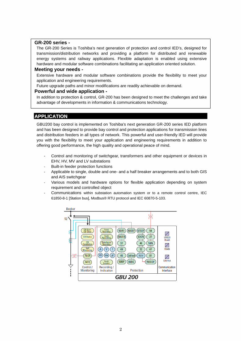
GBU200 bay control is implemented on Toshiba’s next generation GR-200 series IED platform and has been designed to provide bay control and protection applications for transmission lines and distribution feeders in all types of network. This powerful and user-friendly IED will provide you with the flexibility to meet your application and engineering requirements in addition to offering good performance, the high quality and operational peace of mind.
- Control and monitoring of switchgear, transformers and other equipment or devices in EHV, HV, MV and LV substations
- Built-in feeder protection functions - Applicable to single, double and one- and a half breaker arrangements and to both GIS
and AIS switchgear - Various models and hardware options for flexible application depending on system
requirement and controlled object - Communications within substation automation system or to a remote control centre, IEC
61850-8-1 [Station bus], Modbus® RTU protocol and IEC 60870-5-103.
51V
3
FFEEAATTUURREESS• Application - For control and monitoring of switchgear,
transformers and other equipment or devices in EHV, HV, MV and LV substations
- Built-in feeder protection functions - Applicable to single, double and one- and a
half breaker arrangements and to both GIS and AIS switchgear
• Functionality - Synchronization check and dead-line check
function for single- or multi-breaker arrangements
- Analog measurement accuracy up to 0.5% for power, current and voltage
- Power quality measurement and monitoring (option)
- Integrated disturbance and event recorder - Time synchronization - Self-supervision - Parameters with password protection - Simulation and test functions for
communication, control and protection • Communication - Data communication for station bus by IEC
61850 and Modbus RTU
- Data communication by IEC 60870-5-103 and Modbus RTU
- Local setting and testing facility from a front USB port using an engineering tool software (TOSHIBA IED Engineering & Monitoring Software) on a laptop
• Security - Password protection • Flexibility - Various models and hardware options for
flexible application depending on system requirement and controlled object
- Programmable control, trip and alarm logic with PLC tool software
- Simple engineering on configurable function-base platform
• Human Machine Interface - LCD (large or standard) and 26 LEDs for
local human-machine interface - Single line diagram indication and
touch-type operation on LCD (large LCD only)
- Configurable 7 function keys and direct control buttons for open/close (O/I) and control authority (43R/L).
FFUUNNCCTTIIOONNSS
• Control - Circuit breaker and isolator control - Switchgear interlock check - Transformer tap change control - Synchronism voltage check - Autoreclose (upto 5 shot) - Programmable automatic sequence control - Manual override
• Monitoring - Status and condition monitoring of primary
apparatus - Switchgear operation monitoring - Plausibility check - Measurement of I, V, P, Q, PF, f, Wh and
varh
- Measurement and supervision of individual and total harmonic up to 15th, sag, swell, interruption (option)
- DC analog input (for transducer input) - DC analog output (for transducer output) - Current and voltage circuit supervision - Trip circuit supervision - Fault locator
• Protection - Directional or non-directional overcurrent
and earth fault protection - Sensitive directional or non-directional earth
fault protection - Directional or non-directional negative
sequence overcurrent protection

4
- Undercurrent protection - Negative sequence overvoltage protection - Thermal overload protection - Under- and over-voltage protection - Under- and over-frequency protection - Rate-of-change of frequency - Directional power protection - Broken conductor detection - Circuit breaker fail - Cold load protection - High-impedance differential protection - Switch-on-to fault protection - Voltage controlled overcurrent • HMI function - Selection of HMI: Standard LCD / large
LCD / Separate large LCD - Large LCD supports single line diagram
indication and touch-type operation or multi-language option
- 24 configurable tri-state LEDs selectable red/green/yellow
- 7 Programmable function keys for user demand operation
• Recording - Fault record - Event record - Disturbance record
• Communication - IEC 60870-5-103 / IEC 61850 - Modbus® RTU / Modbus® TCP/IP
• General functions - Eight settings groups - Automatic supervision - Metering and recording functions - Time synchronization by external clock using
IRIG-B or system network - Password protection for settings and
selection of local / remote control - Checking internal circuit by forcible
signal. - Checking internal circuit using monitoring
jacks.
AAPPPPLLIICCAATTIIOONNSS
Control is performed remotely through the communication bus or locally from an HMI on the front panel showing the single line diagram for the bay or a menu. GBU200 can be applied in a standard configuration of one unit per bay, or alternatively one unit can be applied as a common device for several bays. The GBU200 also provides protection features. Basic functions for feeder protection are equipped and configuration of addition/deletion of other protection functions is possible using professional version of the engineering tool (TOSHIBA IED Engineering & Monitoring Software). Printed circuit boards for binary inputs/outputs, CT/PT modules, DCAI/DCAO modules and communication modules are configurably selectable upon users’ requirement and applications, and configured by simple
engineering work with the engineering tool software. The GBU200 can operate as a control terminal within the substation automation system (SAS). The GBU200 can communicate with a server of the SAS by IE 61850 or Modbus® RTU. The GBU200 can communicate with conventional equipment such as legacy relays by hard-wiring and other protection relays or control units over IEC 61850-5-103 or Modbus RTU, and the GBU200 can also function as a protocol converter to communicate with the SAS.
5
CONTROL
� Switchgear Control
GBU200 provides functions for local control of
switchgear from the HMI. Two-stepped operation
(select-control) or direct control operation is applied
for the control of circuit breakers, isolator switches
and earthing switches.
Also, switchgear control commands from the station
level can be performed through GBU200 within the
application of a SAS.
� Interlock check
The interlocking function blocks the operation of
primary switching devices, for instance when a
isolator switch is under load, in order to prevent
material damage and/or accidental human injury.
Each switchgear control function has interlocking
modules included for different switchyard
arrangements, where each function handles
interlocking for one bay. The interlocking function is
distributed to each IED and is not dependent on any
central function.
For station-level interlocking scheme, GBU200
communicates via the station bus or by hard-wiring.
The interlocking conditions depend on the circuit
configuration and apparatus position status at any
given time. For easy and safe implementation of the
interlocking function, standard software interlocking
logic is provided in GBU200. The interlocking logic
and conditions can be modified to satisfy the specific
requirements by means of the graphical configuration
tool.
� Synchronism and voltage check
When the circuit breaker closing selection command
is received, the integrated synchronism and voltage
check function is performed to check feeder
synchronization.
� Split synchronism check
In case the circuit breaker closing command is
received during an asynchronous network condition
where frequencies are different between the line and
bus sides, the split synchronism check mode
automatically functions by detecting angle differences,
instead of normal synchronism check mode.
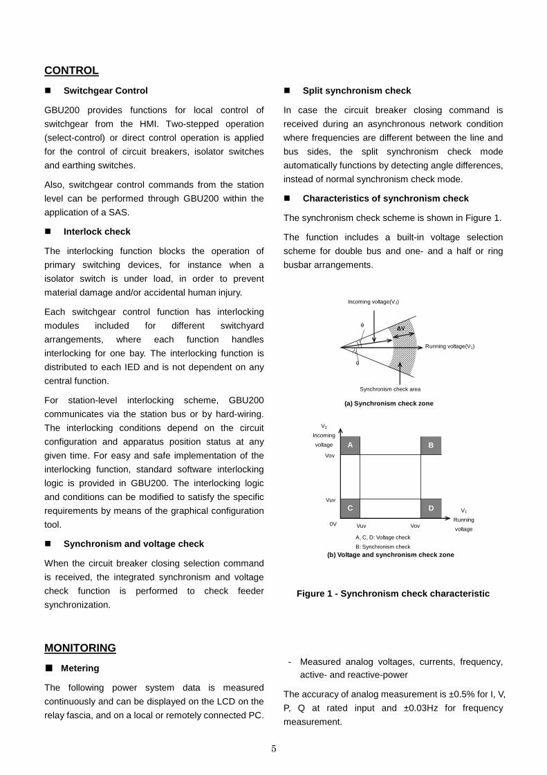
� Characteristics of synchronism check
The synchronism check scheme is shown in Figure 1.
The function includes a built-in voltage selection
scheme for double bus and one- and a half or ring
busbar arrangements.
Figure 1 - Synchronism check characteristic
MONITORING
■ Metering
The following power system data is measured
continuously and can be displayed on the LCD on the
relay fascia, and on a local or remotely connected PC.
- Measured analog voltages, currents, frequency, active- and reactive-power
The accuracy of analog measurement is ±0.5% for I, V,
P, Q at rated input and ±0.03Hz for frequency
measurement.
(a) Synchronism check zone
∆V θ
Running voltage(V1)
Incoming voltage(V2)
Synchronism check area
θ
(b) Voltage and synchronism check zone
C D
B A
0V
Vuv
Vov
A, C, D: Voltage check
B: Synchronism check
Vuv Vov
V2
Incoming
voltage
V1
Running
voltage
6
■ Status Monitoring
The open or closed status of each switchgear device
and failure information concerning power apparatus
and control equipment are monitored by GBU200.
Both normally open and normally closed contacts are
used to monitor the switchgear status. If an unusual
status is detected, a switchgear abnormality alarm is
generated.
� DC analog inputs and outputs (option)
The DC analog inputs provide monitoring and
supervision of measurement and process signals from
measuring transducers. Many monitoring devices
used in substation apparatus represent various
parameters such as temperature, GIS gas pressure
and DC battery voltage as low current values.
These transducer inputs are also monitored on the
local HMI or SAS.
� Power Quality Measurement (option)
GBU200 provides power quality measurement
features for the supervision of power system values.
This function is available using an optional CT/PT
card.
• Individual harmonic distortion from 2nd to 15th
• Total Harmonic Distortion (THD) and Total Demand
Distortion (TDD) from 2nd to 15th
• Sag, Swell and Interruption
PROTECTION
� Directional or non-directional phase
overcurrent protection (OC)
Four steps of three-phase overcurrent functions have
definite time or inverse time characteristics in which all
IEC, ANSI and user-defined characteristics are
available.
The function can be set to be directional or
non-directional characteristics independently.
� Directional or non-directional earth fault
overcurrent protection (EF)
Four steps of earth fault overcurrent protection have
definite time or inverse time characteristics in which all
IEC, ANSI and optional user-defined characteristics
are available.
The function can be set to be directional or
non-directional characteristics independently.
� Sensitive directional or non-directional earth
fault overcurrent protection (SEF) (Option)
This function provides two steps of earth fault overcurrent protection with more sensitive settings for use in applications where the fault current magnitude may be very low.
The sensitive earth fault quantity is measured directly, using a dedicated core balance earth fault CT.
The function can be set to be directional or
non-directional independently.
� Thermal overload protection (THM)
The thermal overload feature provides protection for
cables and other plant against the effects of prolonged
operation under excess load conditions. A thermal
replica algorithm is applied to create a model for the
thermal characteristics of the protected plant. Tripping
times depend not only on the level of overload current,
but also on the level of prior load current, the thermal
replica providing ‘memory’ of previous conditions.
� Under and over voltage protection (UV/OV)
Both undervoltage and overvoltage protection
schemes are provided. Each scheme can be
programmed with definite or inverse time delay.
� Frequency protection (FRQ)
6 independent frequency stages are provided. Each is
programmable for either under-frequency or
over-frequency operation, and each has an associated
DTL timer. The underfrequency function can be
applied to implement load-shedding schemes.
� Negative sequence overcurrent protection
(OCN)
Two steps of negative sequence overcurrent
protection have definite time or inverse time
characteristics.
The function can be set to be directional or
non-directional characteristics independently.

7
� Voltage Controlled Protection
Voltage controlled or voltage restraint inverse
overcurrent protection is equipped so that the relay
can issue a trip signal in response to certain fault
types on the lower voltage side of a transformer when
the fault current may be lower than the nominal value.
The user can select either the voltage controlled OCI
or the voltage restraint OCI function in addition to the
normal OCI function. When voltage controlled OCI is
used, only when an input voltage is lower than a
setting, the OCI element functions. When voltage
restraint OCI is used, the sensitivity of OCI is
proportionally adjusted by the voltage input value
between 20 and 100% of the voltage setting.
� Broken Conductor Protection
The unbalance condition caused by an open circuited
conductor is detected by the broken conductor protection.
An unbalance threshold with programmable definite
time delay is provided.
� Circuit Breaker Fail Protection (CBF)
Two stage CBF protection provides outputs for
re-tripping of the local circuit breaker and/or
back-tripping to upstream circuit breakers. The CBF
functions can also be initiated by external protections
via a binary input if required.
� Cold Load Protection
The cold load function modifies the overcurrent protection
settings by changing the setting group for a period
after energising the system. This feature is used to
prevent unwanted protection operation when closing on
to the type of load which takes a high level of current
for a period after energization. This is achieved by a
‘Cold Load Settings Group’ in which the user can
program alternative settings. Normally the user will
choose higher current settings and/or longer time
delays and/or disable elements altogether within this
group.
� Auto Reclose (ARC)
Four independent sequences are provided. Each
protection trip such as phase fault, earth fault or an
external trip signal is programmable for instantaneous
or delayed operation and each ARC shot has a
programmable dead time. Either simple ARC shot or
normal ARC shot with synchronization check for
three-phase autoreclose is settable for the first
sequence.
HMI FUNCTION
■ Front Panel
GBU200 provides the following front panel options. - Standard LCD - Large LCD (optional separate LCD type is also
availabe)
The standard LCD panel incorporates the user
interfaces listed below. Setting the relay and viewing
Figure 2 - HMI Panel (large LCD type)
stored data are possible using the Liquid Crystal Display (LCD) and operation keys. - 21 character, 8 line LCD with back light - Support of English language
The large LCD panels incorporates a touch type
screen for control and navigation purposes. - 40 character, 40 line LCD with back light - Support of multi language
(20 character and 26 line LCD for multi-language)
The local human machine interface includes an LCD
which can display the single line diagram for the bay.
The local human machine interface is simple and easy
to understand with the following facilities and
indications. - Status indication LEDs (IN SERVICE, ERROR
and 24 configurable LEDs) - 7 Function keys for control, monitoring, setting
group change and screen jump functions of which operation is configurable by the user
8
- Test terminals which can monitor three different signals from the front panel without connection to the rear terminals.
- USB port
■ Local PC connection
The user can communicate with GBU200 from a local
PC via the USB port on the front panel. Using GR-200
series engineering tool software (called GR-TIEMS),
the user can view, change settings and monitor
real-time measurements.
RECORDING
■ Event Record
Continuous event-logging is useful for monitoring of
the system from an overview perspective and is a
complement to specific disturbance recorder functions.
Up to 1,024 time-tagged events are stored with 1ms
resolution.
■ Fault records
Information about the pre-fault and fault values for
currents and voltages are recorded and displayed for
trip event confirmation. The most recent 8 time-tagged
faults with 1ms resolution are stored. Fault record
items are as follows. - Date and time - Faulted phase - Tripping phase - Operating mode - Pre-fault and post-fault current and voltage data
(phase, phase to phase, symmetrical components)
- Autoreclose operation - Fault location
Fault location is initiated by relay tripping signals.
It can also be started on receipt of a start signal from external relays.
Fault location is indicated in km or mile and % for
the whole length of the protected line. The fault
location is highly accurate for parallel lines due to
the implementation of zero-sequence mutual
impedance compensation.
The result of the fault location is stored as fault
record data.
■ Disturbance records
The Disturbance Recorder function supplies fast,
complete and reliable information for disturbances in
the power system. It facilitates understanding of
system behavior and performance of related primary
and secondary equipment during and after a
disturbance.
The Disturbance Recorder acquires sampled data
from all selected analogue inputs and binary signals.
The data can be stored in COMTRADE format.
COMMUNICATION
■ Station bus
Ethernet port(s) for the substation communication
standards IEC 61850 and Modbus® RTU are
provided for the station bus.
■ Serial communication
Serial port for communicating with legacy equipment
or protection relays over IEC 60870-5-103 or
Modbus® RTU protocol are provided. The GBU200
can function as a protocol converter to connect SAS.
GENERAL FUNCTION
■ Self supervision
Automatic self-supervision of internal circuits and
software is provided. In the event of a failure being
detected, the ALARM LED on the front panel is
illuminated, the ‘UNIT FAILURE’ binary output
operates, and the date and time of the failure is
recorded in the event record.
■ Time synchronization
Current time can be provided with time
synchronization via the station bus by SNTP (Simple
Network Time Protocol) with the IEC 61850 protocol.
IRIG-B port is also available as an option.
■ Setting groups
9
8 settings groups are provided, allowing the user to
set one group for normal conditions, while the other
groups may be set to cover alternative operating
conditions.
■ Password protection
Password protection is available for the execution of
setting changes, executing control, clearing records
and switching between local/remote control.
■ Simulation and test
GBU200 provides simulation and test functions to
check control functions without modification to wiring
provided by a dummy circuit breaker (virtual
equipment), and the capability to test communication
signals by forced signal status change.
The simulation and test can work in the Test mode
only.
TOOLS & ACCESSORY The PC interface GR-TIEMS allows users to access
GBU200 and other Toshiba GR-200 series IEDs from
a local personal computer (PC) to view on-line or
stored data, to change settings, to edit the LCD
screen, to configure sequential logics and for other
purposes.
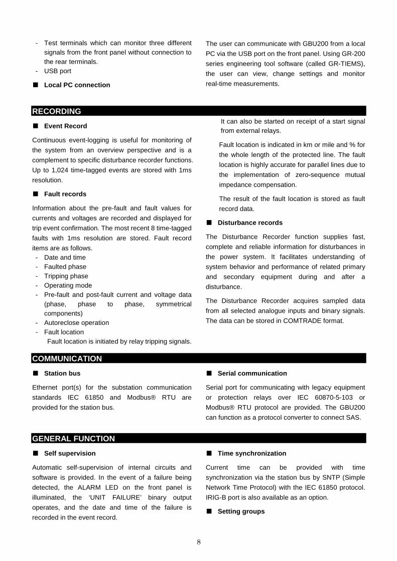
■ REMOTE SETTING AND MONITORING
The engineering tool supports functions to change
settings and to view and analyze fault and disturbance
records stored in GBU200. Waveform data in the
disturbance records can be displayed, edited,
measured and analyzed in detail. An advanced
version of the engineering tool can provide additional
and powerful analysis tools and setting calculation
support functions.
Figure 3 PC Display of GR-TIEMS
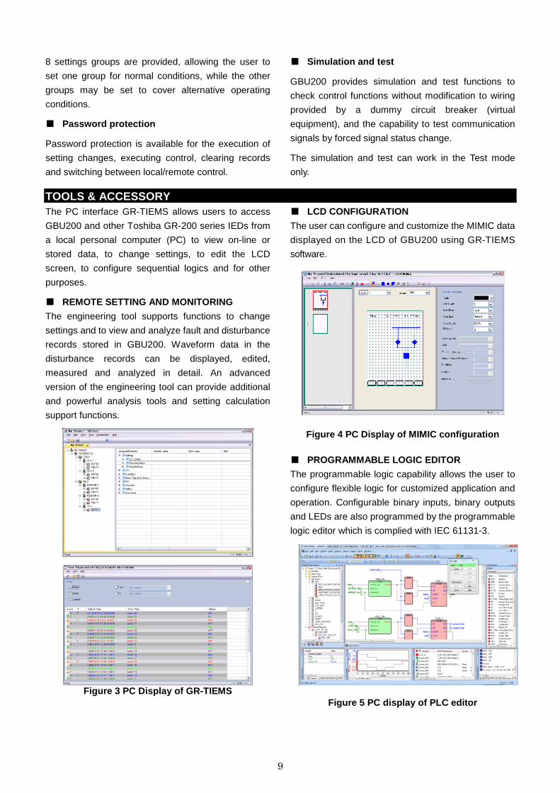
■ LCD CONFIGURATION
The user can configure and customize the MIMIC data
displayed on the LCD of GBU200 using GR-TIEMS
software.
Figure 4 PC Display of MIMIC configuration
■ PROGRAMMABLE LOGIC EDITOR
The programmable logic capability allows the user to
configure flexible logic for customized application and
operation. Configurable binary inputs, binary outputs
and LEDs are also programmed by the programmable
logic editor which is complied with IEC 61131-3.
Figure 5 PC display of PLC editor
10
TECHNICAL DATA
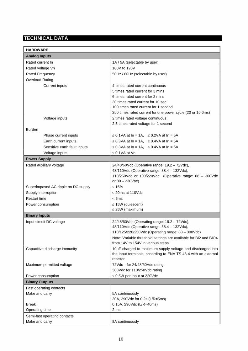
HARDWARE
Analog Inputs
Rated current In 1A / 5A (selectable by user)
Rated voltage Vn 100V to 120V
Rated Frequency 50Hz / 60Hz (selectable by user)
Overload Rating
Current inputs 4 times rated current continuous
5 times rated current for 3 mins 6 times rated current for 2 mins 30 times rated current for 10 sec 100 times rated current for 1 second
250 times rated current for one power cycle (20 or 16.6ms)
Voltage inputs 2 times rated voltage continuous
2.5 times rated voltage for 1 second
Burden
Phase current inputs ≤ 0.1VA at In = 1A, ≤ 0.2VA at In = 5A
Earth current inputs ≤ 0.3VA at In = 1A, ≤ 0.4VA at In = 5A
Sensitive earth fault inputs ≤ 0.3VA at In = 1A, ≤ 0.4VA at In = 5A
Voltage inputs ≤ 0.1VA at Vn
Power Supply
Rated auxiliary voltage 24/48/60Vdc (Operative range: 19.2 – 72Vdc),
48/110Vdc (Operative range: 38.4 – 132Vdc), 110/250Vdc or 100/220Vac (Operative range: 88 – 300Vdc or 80 – 230Vac)
Superimposed AC ripple on DC supply ≤ 15%
Supply interruption ≤ 20ms at 110Vdc
Restart time < 5ms
Power consumption ≤ 15W (quiescent) ≤ 25W (maximum)
Binary Inputs
Input circuit DC voltage 24/48/60Vdc (Operating range: 19.2 – 72Vdc), 48/110Vdc (Operative range: 38.4 – 132Vdc), 110/125/220/250Vdc (Operating range: 88 – 300Vdc)
Note: Variable threshold settings are available for BI2 and BIO4 from 14V to 154V in various steps.
Capacitive discharge immunity 10µF charged to maximum supply voltage and discharged into the input terminals, according to ENA TS 48-4 with an external resistor
Maximum permitted voltage 72Vdc for 24/48/60Vdc rating,
300Vdc for 110/250Vdc rating
Power consumption ≤ 0.5W per input at 220Vdc
Binary Outputs
Fast operating contacts Make and carry
Break Operating time
5A continuously
30A, 290Vdc for 0.2s (L/R=5ms) 0.15A, 290Vdc (L/R=40ms) 2 ms
Semi-fast operating contacts
Make and carry
8A continuously
11
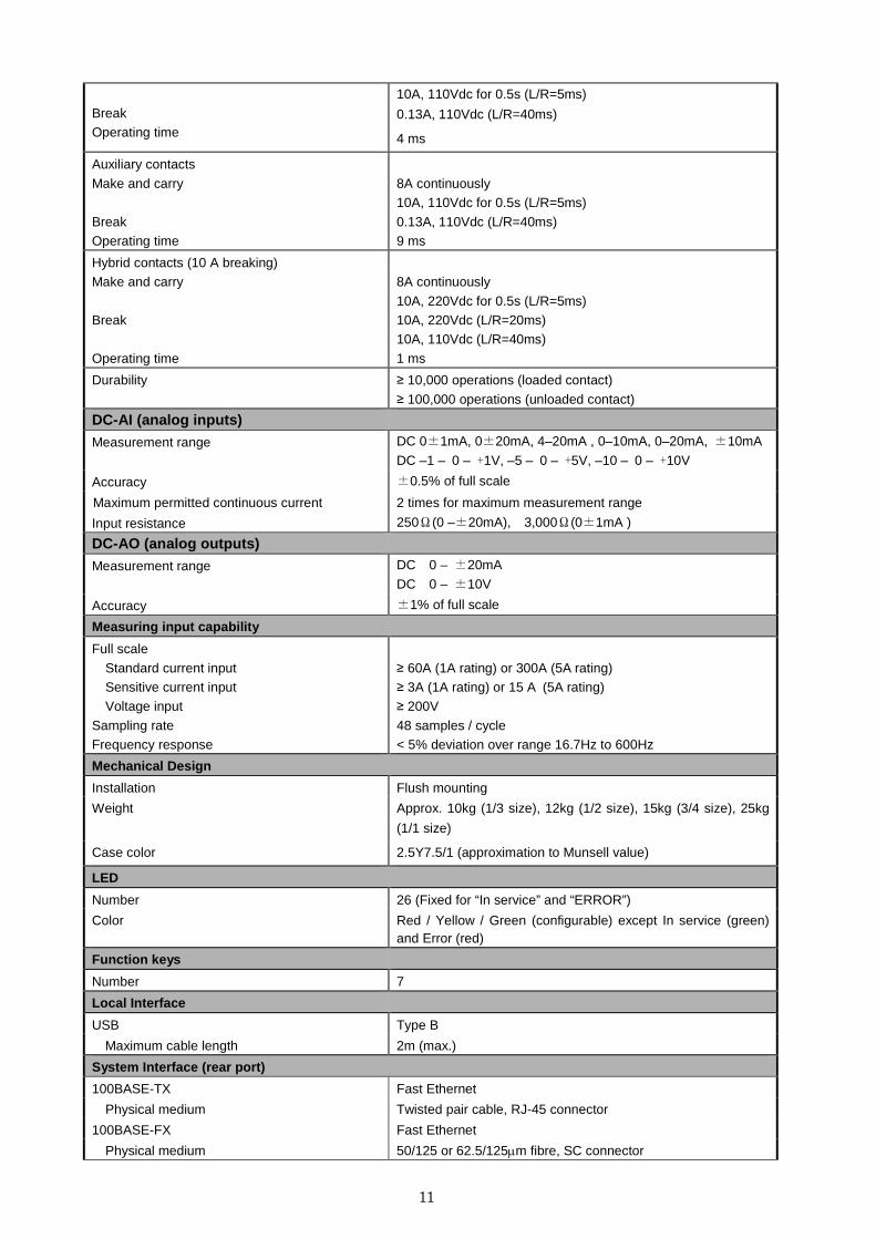
Break Operating time
10A, 110Vdc for 0.5s (L/R=5ms)
0.13A, 110Vdc (L/R=40ms)
4 ms
Auxiliary contacts
Make and carry
Break Operating time
8A continuously 10A, 110Vdc for 0.5s (L/R=5ms)
0.13A, 110Vdc (L/R=40ms) 9 ms
Hybrid contacts (10 A breaking) Make and carry
Break
Operating time
8A continuously
10A, 220Vdc for 0.5s (L/R=5ms) 10A, 220Vdc (L/R=20ms) 10A, 110Vdc (L/R=40ms)
1 ms
Durability ≥ 10,000 operations (loaded contact)
≥ 100,000 operations (unloaded contact)
DC-AI (analog inputs)
Measurement range DC 0±1mA, 0±20mA, 4–20mA , 0–10mA, 0–20mA, ±10mA
DC –1 – 0 – +1V, –5 – 0 – +5V, –10 – 0 – +10V
Accuracy ±0.5% of full scale
Maximum permitted continuous current 2 times for maximum measurement range
Input resistance 250Ω(0 –±20mA), 3,000Ω(0±1mA )
DC-AO (analog outputs)
Measurement range DC 0 – ±20mA
DC 0 – ±10V
Accuracy ±1% of full scale
Measuring input capability
Full scale
Standard current input Sensitive current input Voltage input
Sampling rate Frequency response
≥ 60A (1A rating) or 300A (5A rating) ≥ 3A (1A rating) or 15 A (5A rating) ≥ 200V
48 samples / cycle < 5% deviation over range 16.7Hz to 600Hz
Mechanical Design
Installation Flush mounting
Weight Approx. 10kg (1/3 size), 12kg (1/2 size), 15kg (3/4 size), 25kg
(1/1 size)
Case color 2.5Y7.5/1 (approximation to Munsell value)
LED
Number 26 (Fixed for “In service” and “ERROR”)
Color Red / Yellow / Green (configurable) except In service (green) and Error (red)
Function keys
Number 7
Local Interface
USB Type B
Maximum cable length 2m (max.)
System Interface (rear port)
100BASE-TX Fast Ethernet
Physical medium Twisted pair cable, RJ-45 connector
100BASE-FX Fast Ethernet
Physical medium 50/125 or 62.5/125µm fibre, SC connector

12
Protocol IEC61850 or Modbus® RTU
Serial communication (rear port)
RS485 Protocol
Fiber optical
IEC 60870-5-103 or Modbus® RTU
Protocol IEC 60870-5-103
Terminal Block
CT/VT input M3.5 Ring terminal
Binary input, Binary output M3.5 Ring terminal with 15mm stripping length (for compression type terminal) M3.5 Ring terminal (for ring lug type terminal)
13
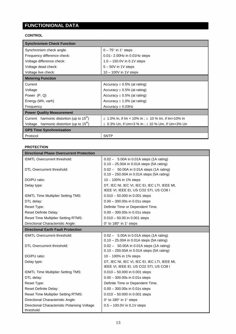
FUNCTIONIONAL DATA
Synchronism Check Function
Synchronism check angle: 0 – 75° in 1° steps
Frequency difference check: 0.01– 2.00Hz in 0.01Hz steps
Voltage difference check: 1.0 – 150.0V in 0.1V steps
Voltage dead check: 5 – 50V in 1V steps
Voltage live check: 10 – 100V in 1V steps
Metering Function
Current Accuracy ± 0.5% (at rating)
Voltage Accuracy ± 0.5% (at rating)
Power (P, Q) Accuracy ± 0.5% (at rating)
Energy (Wh, varh) Accuracy ± 1.0% (at rating)
Frequency Accuracy ± 0.03Hz
Power Quality Measurement
Current harmonic distortion (up to 15th) ± 1.0% In, if Im < 10% In ; ± 10 % Im, if Im>10% In
Voltage harmonic distortion (up to 15th) ± 0.3% Un, if Um<3 % In ; ± 10 % Um, if Um>3% Un
GPS Time Synchronisation
Protocol SNTP
PROTECTION
Directional Phase Overcurrent Protection
IDMTL Overcurrent threshold: 0.02 – 5.00A in 0.01A steps (1A rating) 0.10 – 25.00A in 0.01A steps (5A rating)
DTL Overcurrent threshold: 0.02 – 50.00A in 0.01A steps (1A rating) 0.10 – 250.00A in 0.01A steps (5A rating)
DO/PU ratio: 10 − 100% in 1% steps
Delay type: DT, IEC NI, IEC VI, IEC EI, IEC LTI, IEEE MI, IEEE VI, IEEE EI, US CO2 STI, US CO8 I
IDMTL Time Multiplier Setting TMS: 0.010 – 50.000 in 0.001 steps
DTL delay: 0.00 – 300.00s in 0.01s steps
Reset Type: Definite Time or Dependent Time.
Reset Definite Delay: 0.00 – 300.00s in 0.01s steps
Reset Time Multiplier Setting RTMS: 0.010 – 50.00 in 0.001 steps
Directional Characteristic Angle: 0° to 180° in 1° steps
Directional Earth Fault Protection
IDMTL Overcurrent threshold: 0.02 – 5.00A in 0.01A steps (1A rating) 0.10 – 25.00A in 0.01A steps (5A rating)
DTL Overcurrent threshold: 0.02 – 50.00A in 0.01A steps (1A rating) 0.10 – 250.00A in 0.01A steps (5A rating)
DO/PU ratio: 10 − 100% in 1% steps
Delay type: DT, IEC NI, IEC VI, IEC EI, IEC LTI, IEEE MI, IEEE VI, IEEE EI, US CO2 STI, US CO8 I
IDMTL Time Multiplier Setting TMS: 0.010 – 50.000 in 0.001 steps
DTL delay: 0.00 – 300.00s in 0.01s steps
Reset Type: Definite Time or Dependent Time.
Reset Definite Delay: 0.00 – 300.00s in 0.01s steps
Reset Time Multiplier Setting RTMS: 0.010 – 50.000 in 0.001 steps
Directional Characteristic Angle: 0° to 180° in 1° steps
Directional Characteristic Polarising Voltage threshold:
0.5 – 100.0V in 0.1V steps
CONTROL
14
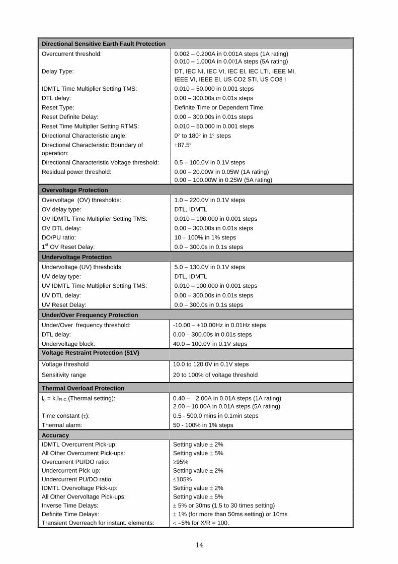
Directional Sensitive Earth Fault Protection
Overcurrent threshold: 0.002 – 0.200A in 0.001A steps (1A rating) 0.010 – 1.000A in 0.001A steps (5A rating)
Delay Type: DT, IEC NI, IEC VI, IEC EI, IEC LTI, IEEE MI, IEEE VI, IEEE EI, US CO2 STI, US CO8 I
IDMTL Time Multiplier Setting TMS: 0.010 – 50.000 in 0.001 steps
DTL delay: 0.00 – 300.00s in 0.01s steps
Reset Type: Definite Time or Dependent Time
Reset Definite Delay: 0.00 – 300.00s in 0.01s steps
Reset Time Multiplier Setting RTMS: 0.010 – 50.000 in 0.001 steps
Directional Characteristic angle: 0° to 180° in 1° steps
Directional Characteristic Boundary of operation:
±87.5°
Directional Characteristic Voltage threshold: 0.5 – 100.0V in 0.1V steps
Residual power threshold: 0.00 – 20.00W in 0.05W (1A rating) 0.00 – 100.00W in 0.25W (5A rating)
Overvoltage Protection
Overvoltage (OV) thresholds: 1.0 – 220.0V in 0.1V steps
OV delay type: DTL, IDMTL
OV IDMTL Time Multiplier Setting TMS: 0.010 – 100.000 in 0.001 steps
OV DTL delay: 0.00 − 300.00s in 0.01s steps
DO/PU ratio: 10 − 100% in 1% steps
1st OV Reset Delay: 0.0 – 300.0s in 0.1s steps
Undervoltage Protection
Undervoltage (UV) thresholds: 5.0 – 130.0V in 0.1V steps
UV delay type: DTL, IDMTL
UV IDMTL Time Multiplier Setting TMS: 0.010 – 100.000 in 0.001 steps
UV DTL delay: 0.00 – 300.00s in 0.01s steps
UV Reset Delay: 0.0 – 300.0s in 0.1s steps
Under/Over Frequency Protection
Under/Over frequency threshold: -10.00 – +10.00Hz in 0.01Hz steps
DTL delay: 0.00 – 300.00s in 0.01s steps
Undervoltage block: 40.0 – 100.0V in 0.1V steps
Voltage Restraint Protection (51V)
Voltage threshold
Sensitivity range
10.0 to 120.0V in 0.1V steps
20 to 100% of voltage threshold
Thermal Overload Protection
Iθ = k.IFLC (Thermal setting): 0.40 – 2.00A in 0.01A steps (1A rating) 2.00 – 10.00A in 0.01A steps (5A rating)
Time constant (τ): 0.5 - 500.0 mins in 0.1min steps
Thermal alarm: 50 - 100% in 1% steps
Accuracy
IDMTL Overcurrent Pick-up: Setting value ± 2%
All Other Overcurrent Pick-ups: Setting value ± 5% Overcurrent PU/DO ratio: ≥95% Undercurrent Pick-up: Setting value ± 2%
Undercurrent PU/DO ratio: ≤105% IDMTL Overvoltage Pick-up: Setting value ± 2% All Other Overvoltage Pick-ups: Setting value ± 5%
Inverse Time Delays: ± 5% or 30ms (1.5 to 30 times setting) Definite Time Delays: ± 1% (for more than 50ms setting) or 10ms Transient Overreach for instant. elements: < −5% for X/R = 100.
15
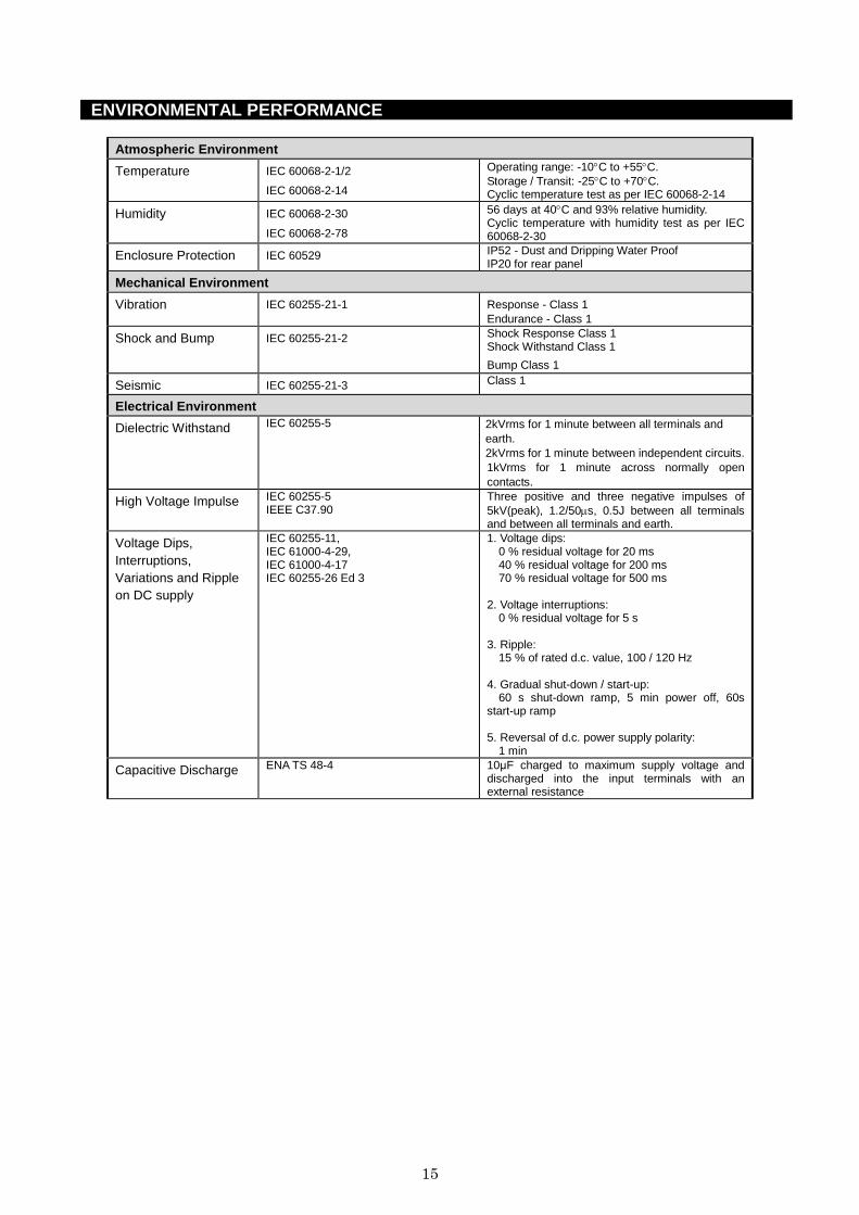
ENVIRONMENTAL PERFORMANCE
Atmospheric Environment
Temperature IEC 60068-2-1/2
IEC 60068-2-14
Operating range: -10°C to +55°C. Storage / Transit: -25°C to +70°C. Cyclic temperature test as per IEC 60068-2-14
Humidity IEC 60068-2-30
IEC 60068-2-78
56 days at 40°C and 93% relative humidity. Cyclic temperature with humidity test as per IEC 60068-2-30
Enclosure Protection IEC 60529 IP52 - Dust and Dripping Water Proof IP20 for rear panel
Mechanical Environment
Vibration IEC 60255-21-1 Response - Class 1 Endurance - Class 1
Shock and Bump IEC 60255-21-2 Shock Response Class 1 Shock Withstand Class 1
Bump Class 1
Seismic IEC 60255-21-3 Class 1
Electrical Environment
Dielectric Withstand IEC 60255-5 2kVrms for 1 minute between all terminals and earth. 2kVrms for 1 minute between independent circuits. 1kVrms for 1 minute across normally open contacts.
High Voltage Impulse IEC 60255-5 IEEE C37.90
Three positive and three negative impulses of 5kV(peak), 1.2/50µs, 0.5J between all terminals and between all terminals and earth.
Voltage Dips, Interruptions, Variations and Ripple on DC supply
IEC 60255-11, IEC 61000-4-29, IEC 61000-4-17 IEC 60255-26 Ed 3
1. Voltage dips: 0 % residual voltage for 20 ms 40 % residual voltage for 200 ms 70 % residual voltage for 500 ms
2. Voltage interruptions:
0 % residual voltage for 5 s 3. Ripple:
15 % of rated d.c. value, 100 / 120 Hz 4. Gradual shut-down / start-up:
60 s shut-down ramp, 5 min power off, 60s start-up ramp 5. Reversal of d.c. power supply polarity:
1 min
Capacitive Discharge ENA TS 48-4 10µF charged to maximum supply voltage and discharged into the input terminals with an external resistance
16
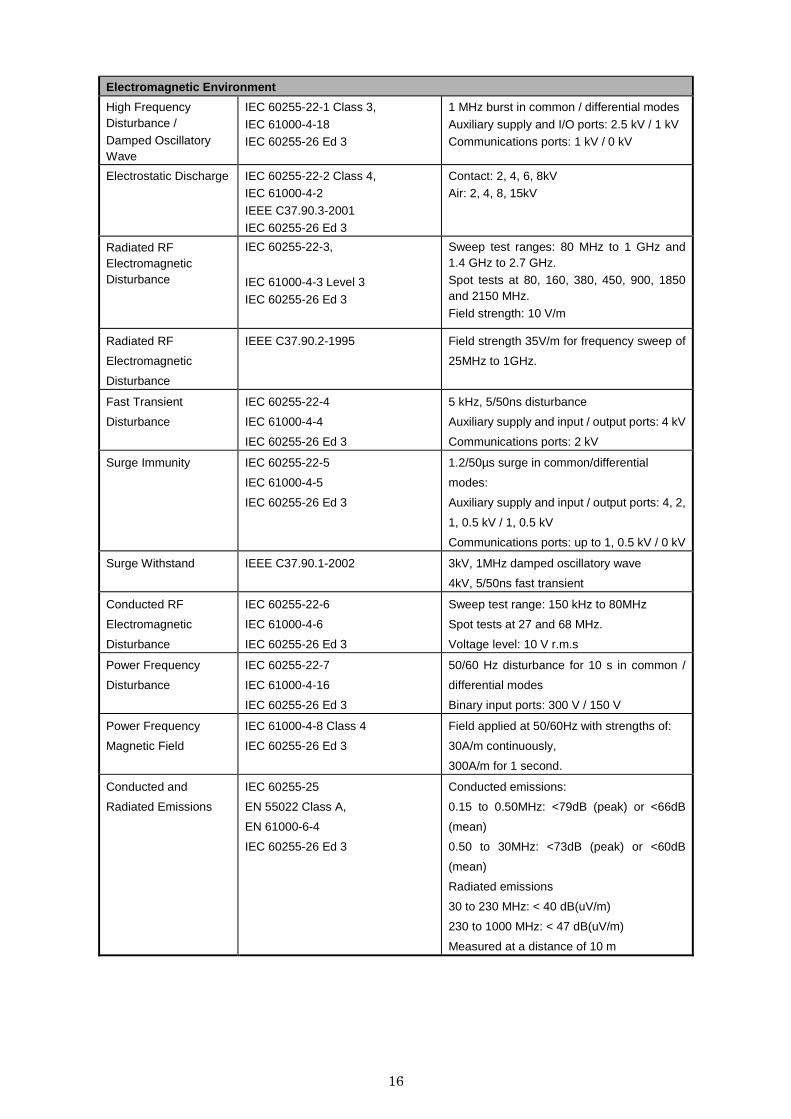
Electromagnetic Environment
High Frequency Disturbance / Damped Oscillatory Wave
IEC 60255-22-1 Class 3,
IEC 61000-4-18 IEC 60255-26 Ed 3
1 MHz burst in common / differential modes
Auxiliary supply and I/O ports: 2.5 kV / 1 kV Communications ports: 1 kV / 0 kV
Electrostatic Discharge IEC 60255-22-2 Class 4, IEC 61000-4-2
IEEE C37.90.3-2001 IEC 60255-26 Ed 3
Contact: 2, 4, 6, 8kV Air: 2, 4, 8, 15kV
Radiated RF Electromagnetic Disturbance
IEC 60255-22-3,
IEC 61000-4-3 Level 3
IEC 60255-26 Ed 3
Sweep test ranges: 80 MHz to 1 GHz and 1.4 GHz to 2.7 GHz. Spot tests at 80, 160, 380, 450, 900, 1850 and 2150 MHz.
Field strength: 10 V/m
Radiated RF
Electromagnetic
Disturbance
IEEE C37.90.2-1995 Field strength 35V/m for frequency sweep of
25MHz to 1GHz.
Fast Transient
Disturbance
IEC 60255-22-4
IEC 61000-4-4
IEC 60255-26 Ed 3
5 kHz, 5/50ns disturbance
Auxiliary supply and input / output ports: 4 kV
Communications ports: 2 kV
Surge Immunity IEC 60255-22-5
IEC 61000-4-5
IEC 60255-26 Ed 3
1.2/50µs surge in common/differential
modes:
Auxiliary supply and input / output ports: 4, 2,
1, 0.5 kV / 1, 0.5 kV
Communications ports: up to 1, 0.5 kV / 0 kV
Surge Withstand IEEE C37.90.1-2002 3kV, 1MHz damped oscillatory wave
4kV, 5/50ns fast transient
Conducted RF
Electromagnetic
Disturbance
IEC 60255-22-6
IEC 61000-4-6
IEC 60255-26 Ed 3
Sweep test range: 150 kHz to 80MHz
Spot tests at 27 and 68 MHz.
Voltage level: 10 V r.m.s
Power Frequency
Disturbance
IEC 60255-22-7
IEC 61000-4-16
IEC 60255-26 Ed 3
50/60 Hz disturbance for 10 s in common /
differential modes
Binary input ports: 300 V / 150 V
Power Frequency
Magnetic Field
IEC 61000-4-8 Class 4
IEC 60255-26 Ed 3
Field applied at 50/60Hz with strengths of:
30A/m continuously,
300A/m for 1 second.
Conducted and
Radiated Emissions
IEC 60255-25
EN 55022 Class A,
EN 61000-6-4
IEC 60255-26 Ed 3
Conducted emissions:
0.15 to 0.50MHz: <79dB (peak) or <66dB
(mean)
0.50 to 30MHz: <73dB (peak) or <60dB
(mean)
Radiated emissions
30 to 230 MHz: < 40 dB(uV/m)
230 to 1000 MHz: < 47 dB(uV/m)
Measured at a distance of 10 m
17
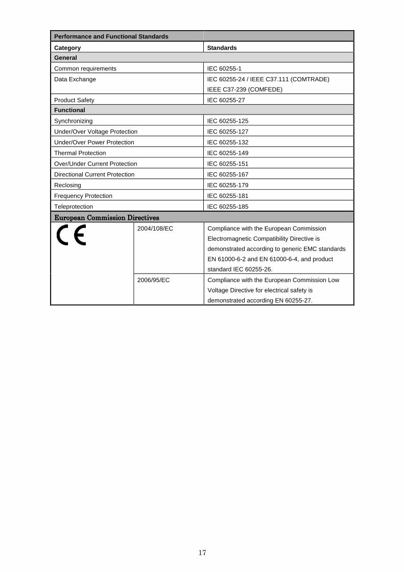
Performance and Functional Standards
Category Standards
General
Common requirements IEC 60255-1
Data Exchange IEC 60255-24 / IEEE C37.111 (COMTRADE)
IEEE C37-239 (COMFEDE)
Product Safety IEC 60255-27
Functional
Synchronizing IEC 60255-125
Under/Over Voltage Protection IEC 60255-127
Under/Over Power Protection IEC 60255-132
Thermal Protection IEC 60255-149
Over/Under Current Protection IEC 60255-151
Directional Current Protection IEC 60255-167
Reclosing IEC 60255-179
Frequency Protection IEC 60255-181
Teleprotection IEC 60255-185
European Commission DirectivesEuropean Commission DirectivesEuropean Commission DirectivesEuropean Commission Directives
2004/108/EC
Compliance with the European Commission
Electromagnetic Compatibility Directive is
demonstrated according to generic EMC standards
EN 61000-6-2 and EN 61000-6-4, and product
standard IEC 60255-26.
2006/95/EC
Compliance with the European Commission Low
Voltage Directive for electrical safety is
demonstrated according EN 60255-27.
18
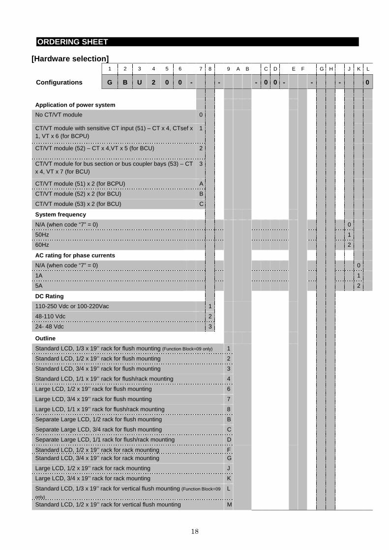
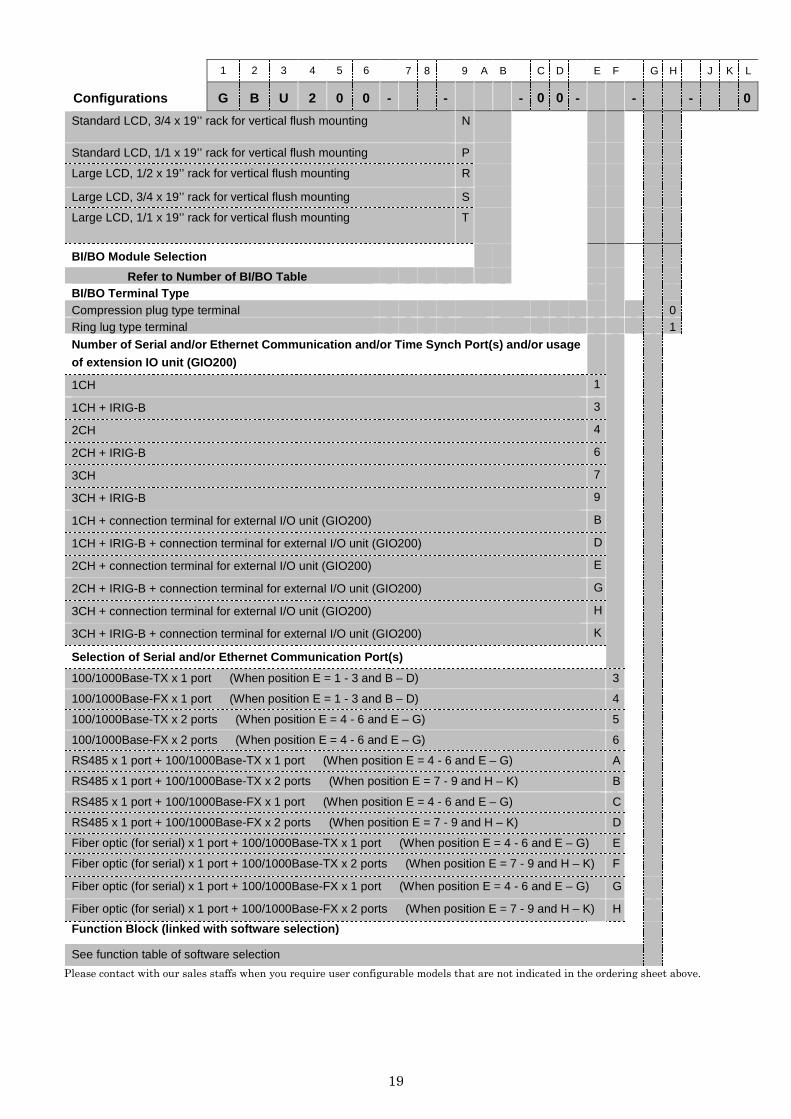
ORDERING SHEET
[Hardware selection] 1 2 3 4 5 6 7 8 9 A B C D E F G H J K L
Configurations G B U 2 0 0 - - - 0 0 - - - 0
Application of power system
No CT/VT module 0
CT/VT module with sensitive CT input (51) – CT x 4, CTsef x 1, VT x 6 (for BCPU)
1
CT/VT module (52) – CT x 4,VT x 5 (for BCU) 2
CT/VT module for bus section or bus coupler bays (53) – CT x 4, VT x 7 (for BCU)
3
CT/VT module (51) x 2 (for BCPU) A
CT/VT module (52) x 2 (for BCU) B
CT/VT module (53) x 2 (for BCU) C
System frequency
N/A (when code “7” = 0) 0
50Hz 1
60Hz 2
AC rating for phase currents
N/A (when code “7” = 0) 0
1A 1
5A 2
DC Rating
110-250 Vdc or 100-220Vac 1
48-110 Vdc 2
24- 48 Vdc 3
Outline
Standard LCD, 1/3 x 19’’ rack for flush mounting (Function Block=09 only) 1
Standard LCD, 1/2 x 19’’ rack for flush mounting 2
Standard LCD, 3/4 x 19’’ rack for flush mounting 3
Standard LCD, 1/1 x 19’’ rack for flush/rack mounting 4
Large LCD, 1/2 x 19’’ rack for flush mounting 6
Large LCD, 3/4 x 19’’ rack for flush mounting 7
Large LCD, 1/1 x 19’’ rack for flush/rack mounting 8
Separate Large LCD, 1/2 rack for flush mounting B
Separate Large LCD, 3/4 rack for flush mounting C
Separate Large LCD, 1/1 rack for flush/rack mounting D
Standard LCD, 1/2 x 19’’ rack for rack mounting F Standard LCD, 3/4 x 19’’ rack for rack mounting G
Large LCD, 1/2 x 19’’ rack for rack mounting J
Large LCD, 3/4 x 19’’ rack for rack mounting K
Standard LCD, 1/3 x 19’’ rack for vertical flush mounting (Function Block=09
only) L
Standard LCD, 1/2 x 19’’ rack for vertical flush mounting M
19
1 2 3 4 5 6 7 8 9 A B C D E F G H J K L
Configurations G B U 2 0 0 - - - 0 0 - - - 0
Standard LCD, 3/4 x 19’’ rack for vertical flush mounting N
Standard LCD, 1/1 x 19’’ rack for vertical flush mounting P
Large LCD, 1/2 x 19’’ rack for vertical flush mounting R
Large LCD, 3/4 x 19’’ rack for vertical flush mounting S
Large LCD, 1/1 x 19’’ rack for vertical flush mounting T
BI/BO Module Selection
Refer to Number of BI/BO Table
BI/BO Terminal Type Compression plug type terminal 0 Ring lug type terminal 1
Number of Serial and/or Ethernet Communication and/or Time Synch Port(s) and/or usage
of extension IO unit (GIO200)
1CH 1
1CH + IRIG-B 3
2CH 4
2CH + IRIG-B 6
3CH 7
3CH + IRIG-B 9
1CH + connection terminal for external I/O unit (GIO200) B
1CH + IRIG-B + connection terminal for external I/O unit (GIO200) D
2CH + connection terminal for external I/O unit (GIO200) E
2CH + IRIG-B + connection terminal for external I/O unit (GIO200) G
3CH + connection terminal for external I/O unit (GIO200) H
3CH + IRIG-B + connection terminal for external I/O unit (GIO200) K
Selection of Serial and/or Ethernet Communication Port (s)
100/1000Base-TX x 1 port (When position E = 1 - 3 and B – D) 3
100/1000Base-FX x 1 port (When position E = 1 - 3 and B – D) 4
100/1000Base-TX x 2 ports (When position E = 4 - 6 and E – G) 5
100/1000Base-FX x 2 ports (When position E = 4 - 6 and E – G) 6
RS485 x 1 port + 100/1000Base-TX x 1 port (When position E = 4 - 6 and E – G) A
RS485 x 1 port + 100/1000Base-TX x 2 ports (When position E = 7 - 9 and H – K) B
RS485 x 1 port + 100/1000Base-FX x 1 port (When position E = 4 - 6 and E – G) C
RS485 x 1 port + 100/1000Base-FX x 2 ports (When position E = 7 - 9 and H – K) D
Fiber optic (for serial) x 1 port + 100/1000Base-TX x 1 port (When position E = 4 - 6 and E – G) E
Fiber optic (for serial) x 1 port + 100/1000Base-TX x 2 ports (When position E = 7 - 9 and H – K) F
Fiber optic (for serial) x 1 port + 100/1000Base-FX x 1 port (When position E = 4 - 6 and E – G) G
Fiber optic (for serial) x 1 port + 100/1000Base-FX x 2 ports (When position E = 7 - 9 and H – K) H
Function Block (linked with software selection)
See function table of software selection
Please contact with our sales staffs when you require user configurable models that are not indicated in the ordering sheet above.
20
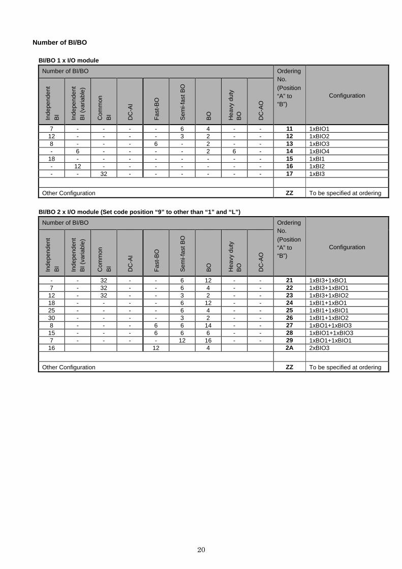
Number of BI/BO
BI/BO 1 x I/O module
Number of BI/BO Ordering No. (Position “A” to “B”)
Configuration
Inde
pend
ent
BI
Inde
pend
ent
BI (
varia
ble)
Com
mon
BI
DC
-AI
Fas
t-B
O
Sem
i-fas
t BO
BO
Hea
vy d
uty
BO
DC
-AO
7 - - - - 6 4 - - 11 1xBIO1 12 - - - - 3 2 - - 12 1xBIO2 8 - - - 6 - 2 - - 13 1xBIO3 - 6 - - - - 2 6 - 14 1xBIO4
18 - - - - - - - - 15 1xBI1 - 12 - - - - - - - 16 1xBI2 - - 32 - - - - - - 17 1xBI3
Other Configuration ZZ To be specified at ordering
BI/BO 2 x I/O module (Set code position “9” to othe r than “1” and “L”)
Number of BI/BO Ordering No. (Position “A” to “B”)
Configuration
Inde
pend
ent
BI
Inde
pend
ent
BI (
varia
ble)
Com
mon
BI
DC
-AI
Fas
t-B
O
Sem
i-fas
t BO
BO
Hea
vy d
uty
BO
DC
-AO
- - 32 - - 6 12 - - 21 1xBI3+1xBO1 7 - 32 - - 6 4 - - 22 1xBI3+1xBIO1
12 - 32 - - 3 2 - - 23 1xBI3+1xBIO2 18 - - - - 6 12 - - 24 1xBI1+1xBO1 25 - - - - 6 4 - - 25 1xBI1+1xBIO1 30 - - - - 3 2 - - 26 1xBI1+1xBIO2 8 - - - 6 6 14 - - 27 1xBO1+1xBIO3
15 - - - 6 6 6 - - 28 1xBIO1+1xBIO3 7 - - - - 12 16 - - 29 1xBO1+1xBIO1
16 12 4 2A 2xBIO3
Other Configuration ZZ To be specified at ordering
21
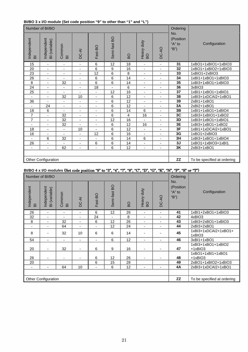
BI/BO 3 x I/O module (Set code position “9” to othe r than “1” and “L”)
Number of BI/BO Ordering No. (Position “A” to “B”)
Configuration
Inde
pend
ent
BI
Inde
pend
ent
BI (
varia
ble)
Com
mon
BI
DC
-AI
Fas
t-B
O
Sem
i-fas
t BO
BO
Hea
vy d
uty
BO
DC
-AO
15 - - - 6 12 18 - - 31 1xBO1+1xBIO1+1xBIO3 20 - - - 6 9 16 - - 32 1xBO1+1xBIO2+1xBIO3 23 - - - 12 6 8 - - 33 1xBIO1+2xBIO3 26 - - - 6 6 14 - - 34 1xBI1+1xBO1+1xBIO3 8 - 32 - 6 6 14 - - 35 1xBI3+1xBO1+1xBIO3
24 - - - 18 - 6 - - 36 3xBIO3 25 - - - - 12 16 - - 37 1xBI1+1xBO1+1xBIO1 - - 32 10 - 6 12 - - 38 1xBI3+1xDCAI2+1xBO1
36 - - - - 6 12 - - 39 2xBI1+1xBO1 - 24 - - - 6 12 - - 3A 2xBI2+1xBO1
18 6 - - - 6 14 6 - 3B 1xBI1+1xBO1+1xBIO4 7 - 32 - - 6 4 16 - 3C 1xBI3+1xBIO1+1xBO2 7 - 32 - - 12 16 - - 3D 1xBI3+1xBO1+1xBIO1 - - 32 - - 6 12 16 - 3E 1xBI3+1xBO1+1xBO2
18 - - 10 - 6 12 - - 3F 1xBI1+1xDCAI2+1xBO1 16 - - - 12 6 16 - - 3G 1xBO1+2xBIO3 - 6 32 - - 6 14 6 - 3H 1xBI3+1xBO1+1xBIO4
26 - - - 6 6 14 - - 3J 1xBO1+1xBIO3+1xBI1 - - 62 - - 6 12 - - 3K 2xBI3+1xBO1
Other Configuration ZZ To be specified at ordering
BI/BO 4 x I/O modules ((((Set Set Set Set code position code position code position code position ““““9999”””” to to to to ““““3333””””, , , , ““““4444””””, , , , ““““7777””””, , , , ““““8888””””, , , , ““““CCCC””””, , , , ““““DDDD””””, , , , ““““GGGG””””, , , , ““““KKKK””””, , , , ““““NNNN””””, , , , ““““PPPP””””, , , , ““““SSSS”””” or or or or ““““TTTT””””))))
Number of BI/BO Ordering No. (Position “A” to “B”)
Configuration
Inde
pend
ent
BI
Inde
pend
ent
BI (
varia
ble)
Com
mon
BI
DC
-AI
Fas
t-B
O
Sem
i-fas
t BO
BO
Hea
vy d
uty
BO
DC
-AO
26 - - - 6 12 26 - - 41 1xBI1+2xBO1+1xBIO3 32 - - - 24 - 8 - - 42 4xBIO3 8 - 32 - 6 12 26 - - 43 1xBI3+2xBO1+1xBIO3 - - 64 - - 12 24 - - 44 2xBI3+2xBO1
8 - 32 10 6 6 14 - - 45 1xBI3+1xDCAI2+1xBO1+ 1xBIO3
54 - - - - 6 12 - - 46 3xBI1+1xBO1
20 - 32 - 6 9 16 - - 47 1xBI3+1xBO1+1xBIO2 +1xBIO3
26 - - - 6 12 26 - - 48 1xBO1+1xBI1+1xBO1 +1xBIO3
20 6 15 28 49 2xBO1+1xBIO2+1xBIO3 - - 64 10 - 6 12 - - 4A 2xBI3+1xDCAI2+1xBO1
Other Configuration ZZ To be specified at ordering
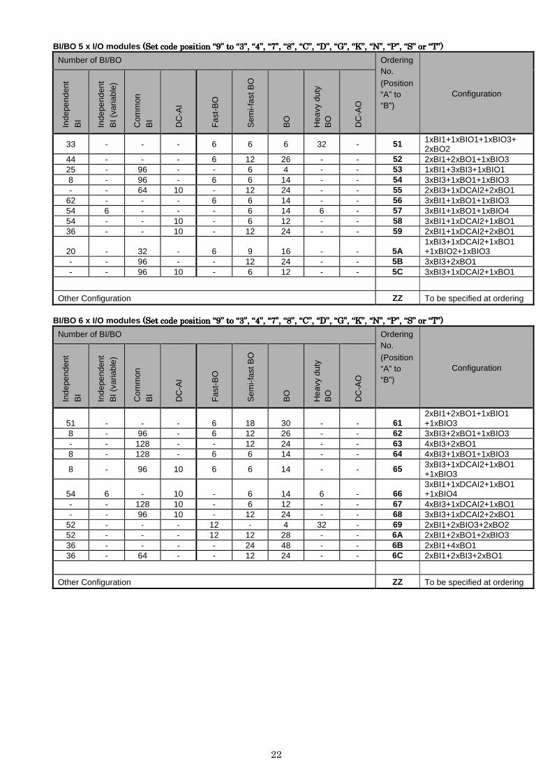
22
BI/BO 5 x I/O modules ((((Set Set Set Set code position code position code position code position ““““9999”””” to to to to ““““3333””””, , , , ““““4444””””, , , , ““““7777””””, , , , ““““8888””””, , , , ““““CCCC””””, , , , ““““DDDD””””, , , , ““““GGGG””””, , , , ““““KKKK””””, , , , ““““NNNN””””, , , , ““““PPPP””””, , , , ““““SSSS”””” or or or or ““““TTTT””””))))
Number of BI/BO Ordering No. (Position “A” to “B”)
Configuration
Inde
pend
ent
BI
Inde
pend
ent
BI (
varia
ble)
Com
mon
BI
DC
-AI
Fas
t-B
O
Sem
i-fas
t BO
BO
Hea
vy d
uty
BO
DC
-AO
33 - - - 6 6 6 32 - 51 1xBI1+1xBIO1+1xBIO3+ 2xBO2
44 - - - 6 12 26 - - 52 2xBI1+2xBO1+1xBIO3 25 - 96 - - 6 4 - - 53 1xBI1+3xBI3+1xBIO1 8 - 96 - 6 6 14 - - 54 3xBI3+1xBO1+1xBIO3 - - 64 10 - 12 24 - - 55 2xBI3+1xDCAI2+2xBO1
62 - - - 6 6 14 - - 56 3xBI1+1xBO1+1xBIO3 54 6 - - - 6 14 6 - 57 3xBI1+1xBO1+1xBIO4 54 - - 10 - 6 12 - - 58 3xBI1+1xDCAI2+1xBO1 36 - - 10 - 12 24 - - 59 2xBI1+1xDCAI2+2xBO1
20 - 32 - 6 9 16 - - 5A 1xBI3+1xDCAI2+1xBO1 +1xBIO2+1xBIO3
- - 96 - - 12 24 - - 5B 3xBI3+2xBO1 - - 96 10 - 6 12 - - 5C 3xBI3+1xDCAI2+1xBO1
Other Configuration ZZ To be specified at ordering
BI/BO 6 x I/O modules ((((Set Set Set Set code position code position code position code position ““““9999”””” to to to to ““““3333””””, , , , ““““4444””””, , , , ““““7777””””, , , , ““““8888””””, , , , ““““CCCC””””, , , , ““““DDDD””””, , , , ““““GGGG””””, , , , ““““KKKK””””, , , , ““““NNNN””””, , , , ““““PPPP””””, , , , ““““SSSS”””” or or or or ““““TTTT””””))))
Number of BI/BO Ordering No.
(Position “A” to “B”)
Configuration
Inde
pend
ent
BI
Inde
pend
ent
BI (
varia
ble)
Com
mon
BI
DC
-AI
Fas
t-B
O
Sem
i-fas
t BO
BO
Hea
vy d
uty
BO
DC
-AO
51 - - - 6 18 30 - - 61 2xBI1+2xBO1+1xBIO1 +1xBIO3
8 - 96 - 6 12 26 - - 62 3xBI3+2xBO1+1xBIO3 - - 128 - - 12 24 - - 63 4xBI3+2xBO1 8 - 128 - 6 6 14 - - 64 4xBI3+1xBO1+1xBIO3
8 - 96 10 6 6 14 - - 65 3xBI3+1xDCAI2+1xBO1 +1xBIO3
54 6 - 10 - 6 14 6 - 66 3xBI1+1xDCAI2+1xBO1 +1xBIO4
- - 128 10 - 6 12 - - 67 4xBI3+1xDCAI2+1xBO1 - - 96 10 - 12 24 - - 68 3xBI3+1xDCAI2+2xBO1
52 - - - 12 - 4 32 - 69 2xBI1+2xBIO3+2xBO2 52 - - - 12 12 28 - - 6A 2xBI1+2xBO1+2xBIO3 36 - - - - 24 48 - - 6B 2xBI1+4xBO1 36 - 64 - - 12 24 - - 6C 2xBI1+2xBI3+2xBO1
Other Configuration ZZ To be specified at ordering
23
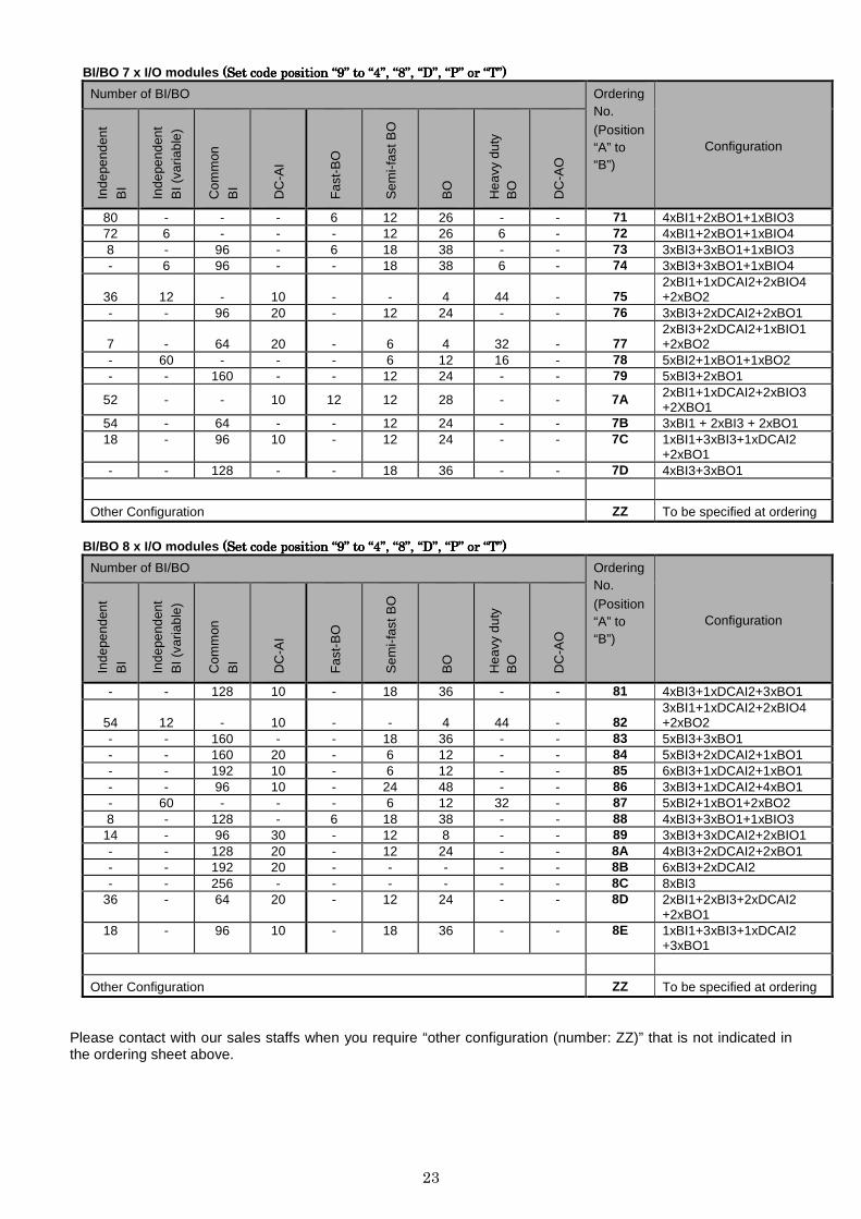
BI/BO 7 x I/O modules ((((Set Set Set Set code position code position code position code position ““““9999”””” to to to to ““““4444””””, , , , ““““8888””””, , , , ““““DDDD””””, , , , ““““PPPP”””” or or or or ““““TTTT””””))))
Number of BI/BO Ordering No. (Position “A” to “B”)
Configuration
Inde
pend
ent
BI
Inde
pend
ent
BI (
varia
ble)
Com
mon
BI
DC
-AI
Fas
t-B
O
Sem
i-fas
t BO
BO
Hea
vy d
uty
BO
DC
-AO
80 - - - 6 12 26 - - 71 4xBI1+2xBO1+1xBIO3 72 6 - - - 12 26 6 - 72 4xBI1+2xBO1+1xBIO4 8 - 96 - 6 18 38 - - 73 3xBI3+3xBO1+1xBIO3 - 6 96 - - 18 38 6 - 74 3xBI3+3xBO1+1xBIO4
36 12 - 10 - - 4 44 - 75 2xBI1+1xDCAI2+2xBIO4 +2xBO2
- - 96 20 - 12 24 - - 76 3xBI3+2xDCAI2+2xBO1
7 - 64 20 - 6 4 32 - 77 2xBI3+2xDCAI2+1xBIO1 +2xBO2
- 60 - - - 6 12 16 - 78 5xBI2+1xBO1+1xBO2 - - 160 - - 12 24 - - 79 5xBI3+2xBO1
52 - - 10 12 12 28 - - 7A 2xBI1+1xDCAI2+2xBIO3 +2XBO1
54 - 64 - - 12 24 - - 7B 3xBI1 + 2xBI3 + 2xBO1 18 - 96 10 - 12 24 - - 7C 1xBI1+3xBI3+1xDCAI2
+2xBO1 - - 128 - - 18 36 - - 7D 4xBI3+3xBO1
Other Configuration ZZ To be specified at ordering
BI/BO 8 x I/O modules ((((Set Set Set Set code position code position code position code position ““““9999”””” to to to to ““““4444””””, , , , ““““8888””””, , , , ““““DDDD””””, , , , ““““PPPP”””” or or or or ““““TTTT””””))))
Number of BI/BO Ordering No.
(Position “A” to “B”)
Configuration
Inde
pend
ent
BI
Inde
pend
ent
BI (
varia
ble)
Com
mon
BI
DC
-AI
Fas
t-B
O
Sem
i-fas
t BO
BO
Hea
vy d
uty
BO
DC
-AO
- - 128 10 - 18 36 - - 81 4xBI3+1xDCAI2+3xBO1
54 12 - 10 - - 4 44 - 82 3xBI1+1xDCAI2+2xBIO4 +2xBO2
- - 160 - - 18 36 - - 83 5xBI3+3xBO1 - - 160 20 - 6 12 - - 84 5xBI3+2xDCAI2+1xBO1 - - 192 10 - 6 12 - - 85 6xBI3+1xDCAI2+1xBO1 - - 96 10 - 24 48 - - 86 3xBI3+1xDCAI2+4xBO1 - 60 - - - 6 12 32 - 87 5xBI2+1xBO1+2xBO2 8 - 128 - 6 18 38 - - 88 4xBI3+3xBO1+1xBIO3
14 - 96 30 - 12 8 - - 89 3xBI3+3xDCAI2+2xBIO1 - - 128 20 - 12 24 - - 8A 4xBI3+2xDCAI2+2xBO1 - - 192 20 - - - - - 8B 6xBI3+2xDCAI2 - - 256 - - - - - - 8C 8xBI3
36 - 64 20 - 12 24 - - 8D 2xBI1+2xBI3+2xDCAI2 +2xBO1
18 - 96 10 - 18 36 - - 8E 1xBI1+3xBI3+1xDCAI2 +3xBO1
Other Configuration ZZ To be specified at ordering
Please contact with our sales staffs when you require “other configuration (number: ZZ)” that is not indicated in the ordering sheet above.

24
[Software selection]
1 2 3 4 5 6 7 S G T E F U 9 V
Configurations G B U 2 0 0 - 0 - -
Application of power system
Assignment on position “7”
Function Block
Refer to Function Table Communication for Remote / Time Synch. (1)
Assignment on position “E”
Communication for Remote / Time Synch. (2)
Assignment on position “F”
Protocol
Standard (IEC 60870-5-103, Modbus) Standard + IEC 61850 IEC 61850
0 1 2
Outline
Assignment on position “9”
Language
English E
Note: Software selection codes “1” to “7”, “E”, “F” and “9” are common with hardware
selection codes.
25
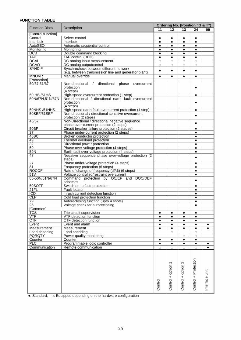
FUNCTION TABLE
Function Block Description Ordering No. (Position “ G & T”) 11 12 13 24 09
[Control function] Control Select-control ● ● ● ● Interlock Interlock ● ● ● ● AutoSEQ Automatic sequential control ● ● ● ● Monitoring Monitoring ● ● ● ● DCB Double command blocking ● ● ● ● TAP TAP control (BCD) ● ● ● ● DCAI DC analog input measurement ○ ○ ○ ○ DCAO DC analog outputcontrol ○ ○ ○ ○ SYNDIF Synchrocheck between different network
(e.g. between transmission line and generator plant) ● ● ● ●
MNOVR Manual override ● ● ● ● [Protection] 50/67,51/67 Non-directional / directional phase overcurrent
protection (4 steps)
●
50 HS /51HS High-speed overcurrent protection (1 step) ● 50N/67N,51N/67N Non-directional / directional earth fault overcurrent
protection (4 steps)
●
50NHS /51NHS High-speed earth fault overcurrent protection (1 step) ● 50SEF/51SEF Non-directional / directional sensitive overcurrent
protection (2 steps) ●
46/67 Non-Directional / directional negative sequence phase over-current protection (2 steps) ●
50BF Circuit breaker failure protection (2 stages) ● 37 Phase under-current protection (2 steps) ● 46BC Broken conductor protection ● 49 Thermal overload protection ● 32 Directional power protection ● 59 Phase over-voltage protection (4 steps) ● 59N Earth fault over-voltage protection (4 steps) ● 47 Negative sequence phase over-voltage protection (2
steps) ●
27 Phase under-voltage protection (4 steps) ● 81 Frequency protection (6 steps) ● ROCOF Rate of change of frequency (df/dt) (6 steps) ● 51V Voltage controlled/restraint overcurrent ● 85-50N/51N/67N Command protection by OC/EF and DOC/DEF
schemes ●
50SOTF Switch on to fault protection ● 21FL Fault locator ● ICD Inrush current detection function ● CLP Cold load protection function ● 79 Autoreclosing function (upto 4 shots) ● 25 Voltage check for autoreclosing ● [Common] TCS Trip circuit supervision ● ● ● ● VTF VTF detection function ● ● ● ● CTF CTF detection function ● ● ● ● Event Event and alarm ● ● ● ● ● Measurement Measurement ● ● ● ● ● Load shedding Load shedding ○ ○ PQRQTY Power quality monitoring ○ ○ Counter Counter ● ● ● ● PLC Programmable logic controller ● ● ● ● ● Communication Remote communication ○ ○ ○ ○ ●
Con
trol
Con
trol
+ o
ptio
n 1
Con
trol
+ o
ptio
n 2
Con
trol
+ P
rote
ctio
n
Inte
rfac
e un
it
●: Standard, ○: Equipped depending on the hardware configuration
26
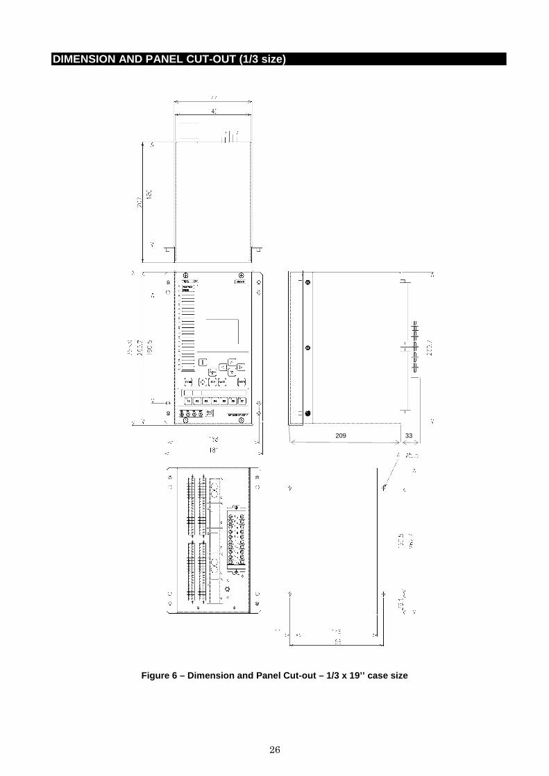
DIMENSION AND PANEL CUT-OUT (1/3 size)
Figure 6 – Dimension and Panel Cut-out – 1/3 x 19’’ case size
209 33
27
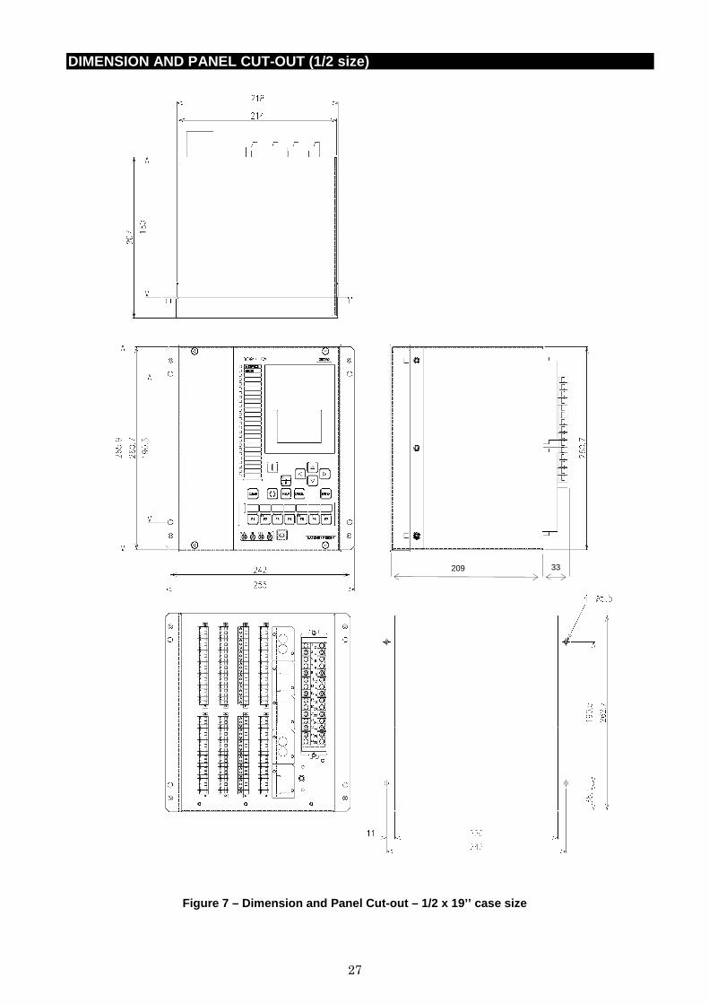
DIMENSION AND PANEL CUT-OUT (1/2 size)
Figure 7 – Dimension and Panel Cut-out – 1/2 x 19’’ case size
209 33
28
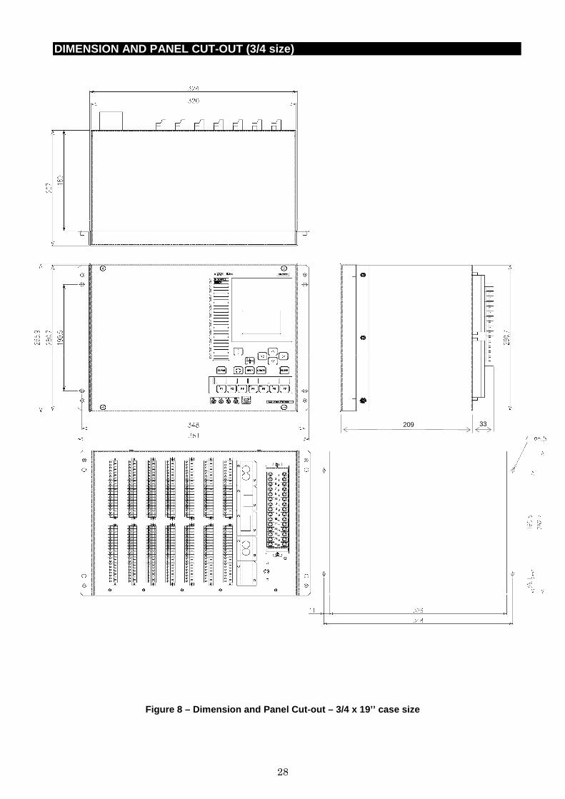
DIMENSION AND PANEL CUT-OUT (3/4 size)
Figure 8 – Dimension and Panel Cut-out – 3/4 x 19’’ case size
209 33
29
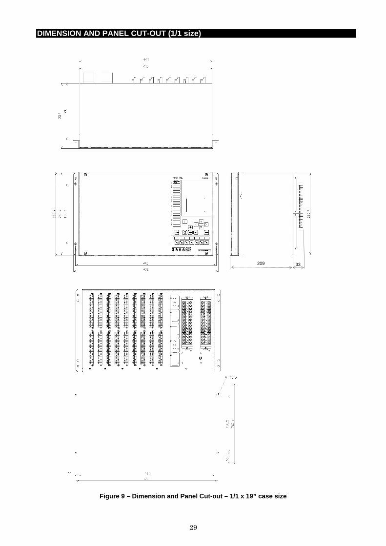
DIMENSION AND PANEL CUT-OUT (1/1 size)
Figure 9 – Dimension and Panel Cut-out – 1/1 x 19” case size
209 33
30
CONNECTIONS DIAGRAM
BI1 A
1
2 BI1
(+)
(-)
3
4 BI2
(+)
(-)
5
6 BI3
(+)
(-)
7
8 BI4
(+)
(-)
9
10 BI5
(+)
(-)
13
14 BI7
(+)
(-)
11
12 BI6
(+)
(-)
15
16 BI8
(+)
(-)
17
18 BI9
(+)
(-)
21
22 BI10
(+)
(-)
23
24 BI11
(+)
(-)
25
26 BI12
(+)
(-)
27
28 BI13
(+)
(-)
29
30 BI14
(+)
(-)
31
32 BI15
(+)
(-)
35
36 BI17
(+)
(-)
33
34 BI16
(+)
(-)
37
38 BI18
(+)
(-)
BI2 A
1
2 BI1
(+)
(-)
5
6 BI2
(+)
(-)
7
8 BI3
(+)
(-)
11
12 BI4
(+)
(-)
13
14 BI5
(+)
(-)
21
22 BI7
(+)
(-)
17
18 BI6
(+)
(-)
25
26 BI8
(+)
(-)
27
28 BI9
(+)
(-)
31
32 BI10
(+)
(-)
33
34 BI11
(+)
(-)
37
38 BI12
(+)
(-)
BI3 A
35
36
(-)
(-)
37
38
(-)
(-)
1 (+) BI1
2 (+) BI2
3 (+) BI3
4 (+) BI4
5 (+) BI5
6 (+) BI6
7 (+) BI7
8 (+) BI8
9 (+) BI9
10 (+) BI10
11 (+) BI11
12 (+) BI12
13 (+) BI13
14 (+) BI14
15 (+) BI15
16 (+) BI16
17 (+) BI17
18 (+) BI18
21 (+) BI19
22 (+) BI20
23 (+) BI21
24 (+) BI22
25 (+) BI23
26 (+) BI24
27 (+) BI25
28 (+) BI26
29 (+) BI27
30 (+) BI28
31 (+) BI29
32 (+) BI30
33 (+) BI31
34 (+) BI32
BO1 A
BO10
21
22
BO1(*2)
1
2
BO2(*2)
3
4
BO3(*2)
5
6
BO4(*2)
7
8
BO5(*2)
9
10
BO6(*2)
11
12
BO7
13
14
BO8
15
16
BO9
17
18
BO11
23
24
BO12
25
26
BO13
27
28
BO14
29
30
BO15
31
32
BO16
33
34
BO17
35
36
BO18
37
38
BO2 A
BO1(*3)
1
2
(+)
(-)
BO2(*3)
3
4
(+)
(-)
BO3(*3)
5
6
(+)
(-)
BO4(*3)
7
8
(+)
(-)
BO5(*3)
9
10
(+)
(-)
BO6(*3)
11
12
(+)
(-)
BO7(*3)
13
14
(+)
(-)
BO8(*3)
15
16
(+)
(-)
BO9(*3)
17
18
(+)
(-)
BO10(*3)
21
22
(+)
(-)
BO11(*3)
23
24
(+)
(-)
BO12(*3)
25
26
(+)
(-)
BO13(*3)
27
28
(+)
(-)
BO14(*3)
29
30
(+)
(-)
BO15(*3)
31
32
(+)
(-)
BO16(*3)
33
34
(+)
(-)
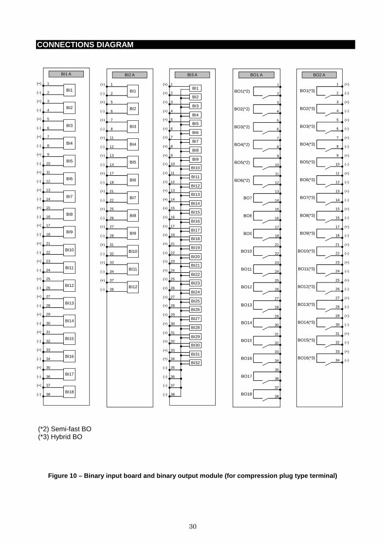
(*2) Semi-fast BO (*3) Hybrid BO
Figure 10 – Binary input board and binary output mo dule (for compression plug type terminal)
31
CONNECTIONS DIAGRAM
BIO1 A
BO1(*2)
15
16
BO2(*2)
17
18
BO3(*2)
21
22
BO4(*2)
23
24
BO5(*2)
25
26
BO6(*2)
27
28
BO7
29
30
BO8
31
32
BO9
33
34
1
2 BI1
(+)
(-)
3
4 BI2
(+)
(-)
5
6 BI3
(+)
(-)
7
8 BI4
(+)
(-)
9
10 BI5
(+)
(-)
13
14 BI7
(+)
(-)
11
12 BI6
(+)
(-)
36
38
35
37
BO10
BIO2 A
BO1(*2)
27
28
BO2(*2)
29
30
BO3(*2)
31
32
BO4
33
34
36
38
35
37
BO5
1
2 BI1
(+)
(-)
3
4 BI2
(+)
(-)
5
6 BI3
(+)
(-)
7
8 BI4
(+)
(-)
9
10 BI5
(+)
(-)
13
14 BI7
(+)
(-)
11
12 BI6
(+)
(-)
15
16 BI8
(+)
(-)
17
18 BI9
(+)
(-)
21
22 BI10
(+)
(-)
23
24 BI11
(+)
(-)
25
26 BI12
(+)
(-)
BIO3 A
BO1(*1)
21
22
BO2(*1)
23
24
BO3(*1)
25
26
BO4(*1)
27
28
BO5(*1)
29
30
BO6(*1)
31
32
BO7
33
34
36
38
35
37
BO8
1
2 BI1
(+)
(-)
3
4 BI2
(+)
(-)
5
6 BI3
(+)
(-)
7
8 BI4
(+)
(-)
9
10 BI5
(+)
(-)
13
14 BI7
(+)
(-)
11
12 BI6
(+)
(-)
15
16 BI8
(+)
(-)
BIO4 A
BO7
33
34
36
38
35
37
BO8
1
2 BI1
(+)
(-)
3
4 BI2
(+)
(-)
5
6 BI3
(+)
(-)
7
8 BI4
(+)
(-)
9
10 BI5
(+)
(-)
11
12 BI6
(+)
(-)
BO1(*3)
17
18
(+)
(-)
BO2(*3)
21
22
(+)
(-)
BO3(*3)
23
24
(+)
(-)
BO4(*3)
25
26
(+)
(-)
BO5(*3)
27
28
(+)
(-)
BO6(*3)
29
30
(+)
(-)
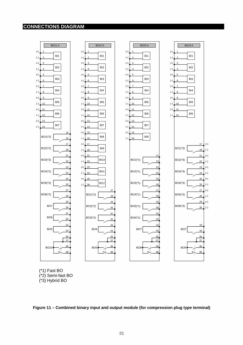
(*1) Fast BO (*2) Semi-fast BO (*3) Hybrid BO
Figure 11 – Combined binary input and output module (for compression plug type terminal)
32
CONNECTIONS DIAGRAM
DCAI2
1
2 DC- AI1
(+)
(-)
18(E)
38(E)
4
5 DC- AI2
(+)
(-)
7
8 DC- AI3
(+)
(-)
10
11 DC- AI4
(+)
(-)
13
14 DC- AI5
(+)
(-)
21
22 DC- AI6
(+)
(-)
24
25 DC- AI7
(+)
(-)
27
28 DC- AI8
(+)
(-)
30
31 DC- AI9
(+)
(-)
33
34 DC- AI10
(+)
(-)
DCAO1
18
38
E
E
1
2
(+)
(-) DC- AO1
3
4
(+)
(-) DC- AO2
5
6
(+)
(-) DC- AO3
7
8
(+)
(-) DC- AO4
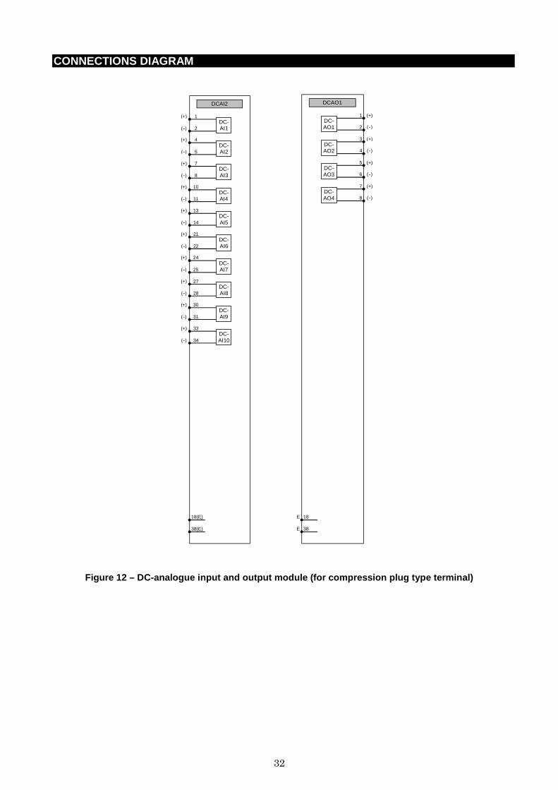
Figure 12 – DC-analogue input and output module (fo r compression plug type terminal)
33
CONNECTIONS DIAGRAM
BI1 A
1
2 BI1
(+)
(-)
3
4 BI2
(+)
(-)
5
6 BI3
(+)
(-)
7
8 BI4
(+)
(-)
9
10 BI5
(+)
(-)
13
14 BI7
(+)
(-)
11
12 BI6
(+)
(-)
15
16 BI8
(+)
(-)
17
18 BI9
(+)
(-)
21
22 BI10
(+)
(-)
23
24 BI11
(+)
(-)
25
26 BI12
(+)
(-)
27
28 BI13
(+)
(-)
29
30 BI14
(+)
(-)
31
32 BI15
(+)
(-)
35
36 BI17
(+)
(-)
33
34 BI16
(+)
(-)
37
38 BI18
(+)
(-)
BI2 A
1
2 BI1
(+)
(-)
5
6 BI2
(+)
(-)
7
8 BI3
(+)
(-)
11
12 BI4
(+)
(-)
13
14 BI5
(+)
(-)
21
22 BI7
(+)
(-)
17
18 BI6
(+)
(-)
25
26 BI8
(+)
(-)
27
28 BI9
(+)
(-)
31
32 BI10
(+)
(-)
33
34 BI11
(+)
(-)
37
38 BI12
(+)
(-)
BI3 A
35
36
(-)
(-)
37
38
(-)
(-)
1 (+) BI1
2 (+) BI2
3 (+) BI3
4 (+) BI4
5 (+) BI5
6 (+) BI6
7 (+) BI7
8 (+) BI8
9 (+) BI9
10 (+) BI10
11 (+) BI11
12 (+) BI12
13 (+) BI13
14 (+) BI14
15 (+) BI15
16 (+) BI16
17 (+) BI17
18 (+) BI18
21 (+) BI19
22 (+) BI20
23 (+) BI21
24 (+) BI22
25 (+) BI23
26 (+) BI24
27 (+) BI25
28 (+) BI26
29 (+) BI27
30 (+) BI28
31 (+) BI29
32 (+) BI30
33 (+) BI31
34 (+) BI32
BO1 A
BO10
21
22
BO1(*2)
1
2
BO2(*2)
3
4
BO3(*2)
5
6
BO4(*2)
7
8
BO5(*2)
9
10
BO6(*2)
11
12
BO7
13
14
BO8
15
16
BO9
17
18
BO11
23
24
BO12
25
26
BO13
27
28
BO14
29
30
BO15
31
32
BO16
33
34
BO17
35
36
BO18
37
38
BO2 A
BO1(*3)
1
2
(+)
(-)
BO2(*3)
3
4
(+)
(-)
BO3(*3)
5
6
(+)
(-)
BO4(*3)
7
8
(+)
(-)
BO5(*3)
9
10
(+)
(-)
BO6(*3)
11
12
(+)
(-)
BO7(*3)
13
14
(+)
(-)
BO8(*3)
15
16
(+)
(-)
BO9(*3)
17
18
(+)
(-)
BO10(*3)
21
22
(+)
(-)
BO11(*3)
23
24
(+)
(-)
BO12(*3)
25
26
(+)
(-)
BO13(*3)
27
28
(+)
(-)
BO14(*3)
29
30
(+)
(-)
BO15(*3)
31
32
(+)
(-)
BO16(*3)
33
34
(+)
(-)
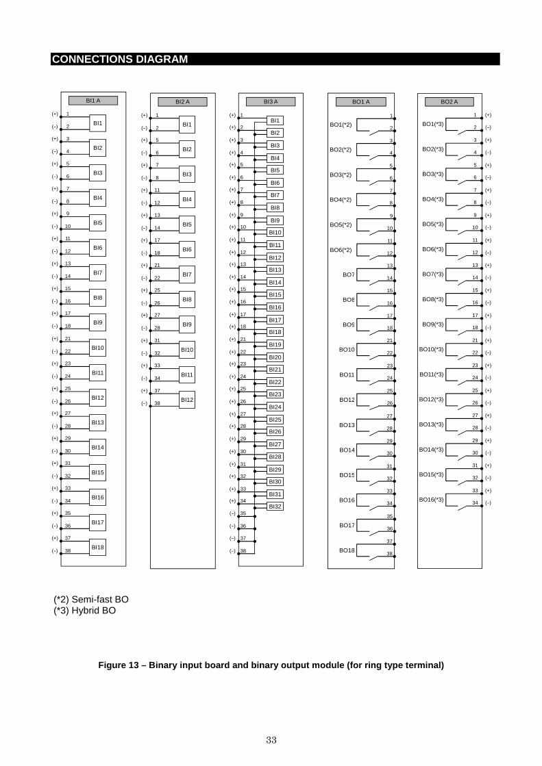
(*2) Semi-fast BO (*3) Hybrid BO
Figure 13 – Binary input board and binary output mo dule (for ring type terminal)
34
CONNECTIONS DIAGRAM
BIO1
A1
B1 BI1
A2
B2 BI2
A3
B3 BI3
A4
B4 BI4
A5
B5 BI5
A6
B6 BI6
A7
B7 BI7
BO1(*2)
A8
B8
BO2(*2)
A9
B9
BO3(*2)
A10
B10
BO4(*2)
A11
B11
BO5(*2)
A12
B12
BO6(*2)
A13
B13
BO7
A14
B14
BO8
A15
B15
BO9
A16
B16
B17
B18
A17
A18
BO10
BIO2
A1
B1 BI1
A2
B2 BI2
A3
B3 BI3
A4
B4 BI4
A5
B5 BI5
A6
B6 BI6
A7
B7 BI7
A8
B8 BI8
A9
B9 BI9
A10
B10 BI10
A11
B11 BI11
A12
B12 BI12
BO1(*2)
A13
B13
BO2(*2)
A14
B14
BO3(*2)
A15
B15
BO4
A16
B16
B17
B18
A17
A18
BO5
BIO3
A1
B1 BI1
A2
B2 BI2
A3
B3 BI3
A4
B4 BI4
A5
B5 BI5
A6
B6 BI6
A7
B7 BI7
A8
B8 BI8
BO1(*1)
A10
B10
BO2(*1)
A11
B11
BO3(*1)
A12
B12
BO4(*1)
A13
B13
BO5(*1)
A14
B14
BO6(*1)
A15
B15
BO7
A16
B16
B17
B18
A17
A18
BO8
BIO4
B17
B18
A17
A18
BO8
A1
B1
(+)
(-)
A2
B2
(+)
(-)
A3
B3
(+)
(-)
A4
B4
(+)
(-)
A5
B5
(+)
(-)
A6
B6
(+)
(-) BI6
BI5
BI4
BI3
BI2
BI1
(*3) BO1 (-)B9
A9 (+)
(*3) BO2 (-)B10
A10 (+)
(*3) BO3 (-)B11
A11 (+)
(*3) BO4 (-)B12
A12 (+)
(*3) BO5 (-)B13
A13 (+)
(*3) BO6 (-)B14
A14 (+)
BO7 B16
A16
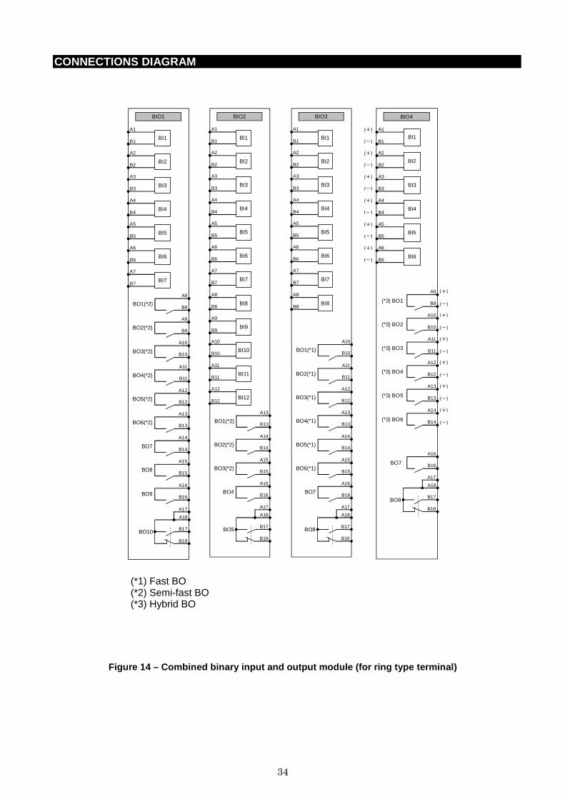
(*1) Fast BO (*2) Semi-fast BO (*3) Hybrid BO
Figure 14 – Combined binary input and output module (for ring type terminal)
35
CONNECTIONS DIAGRAM
DCAI2
A18
A1
A2
(+)
(-)
A3
A4
(+)
(-)
A5
A6
(+)
(-)
A7
A8
(+)
(-)
A9
A10
(+)
(-)
A11
A12
(+)
(-)
A13
A14
(+)
(-)
A15
A16
(+)
(-)
B1
B2
(+)
(-)
E
B18 E
B16
B17 DC- AI10
(+)
(-)
DC- AI9
DC- AI8
DC- AI7
DC- AI6
DC- AI5
DC- AI4
DC- AI3
DC- AI2
DC- AI1
DCAO1
(+)
(-)
(+)
(-)
(+)
(-)
(+)
(-)
A1
B1 DC- AO1
A5
B5 DC- AO2
A9
B9 DC- AO3
A13
B13 DC- AO4
B17 E
B18 E
A17 E
A18 E
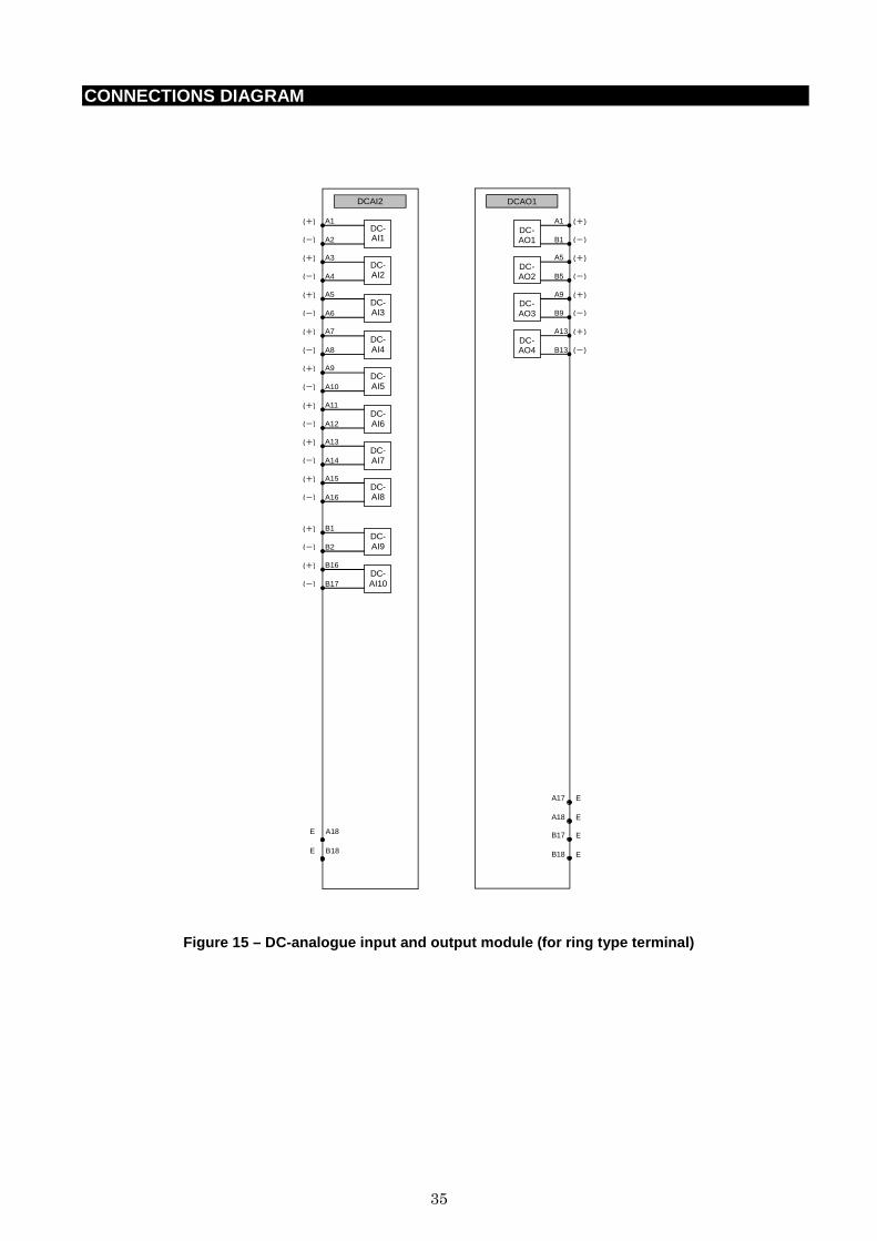
Figure 15 – DC-analogue input and output module (fo r ring type terminal)
36
CONNECTIONS DIAGRAM
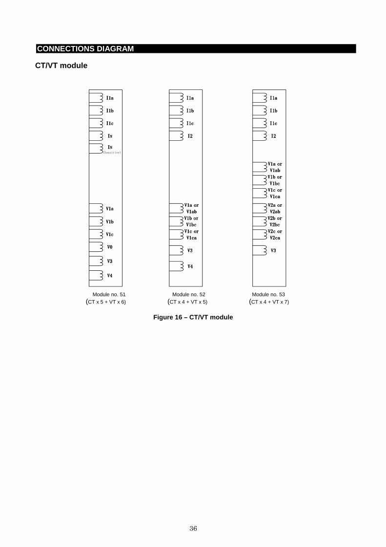
CT/VT module Module no. 51 Module no. 52 Module no. 53 (CT x 5 + VT x 6) (CT x 4 + VT x 5) (CT x 4 + VT x 7)
Figure 16 – CT/VT module
IIII1a1a1a1a
IIII1b1b1b1b
IIII1c1c1c1c
IIIINNNN
VVVV3333
VVVV4444
V1V1V1V1bbbb
VVVV1c1c1c1c
VVVV0000
(Sensitive)
IIIINNNN
V1aV1aV1aV1a
IIII1a1a1a1a
IIII1b1b1b1b
IIII1c1c1c1c
IIII2222
VVVV3333
VVVV1111a ora ora ora or
VVVV1111abababab
VVVV1111b orb orb orb or
VVVV1111bcbcbcbc
VVVV1111c orc orc orc or
VVVV1111cacacaca
V4V4V4V4
IIII1a1a1a1a
IIII1b1b1b1b
IIII1c1c1c1c
IIII2222
VVVV3333
V1aV1aV1aV1a or or or or
V1abV1abV1abV1ab
V1b orV1b orV1b orV1b or
V1bcV1bcV1bcV1bc
V1c orV1c orV1c orV1c or
V1caV1caV1caV1ca
V2a orV2a orV2a orV2a or
V2abV2abV2abV2ab
V2b orV2b orV2b orV2b or
V2bcV2bcV2bcV2bc
V2c orV2c orV2c orV2c or
V2caV2caV2caV2ca
37
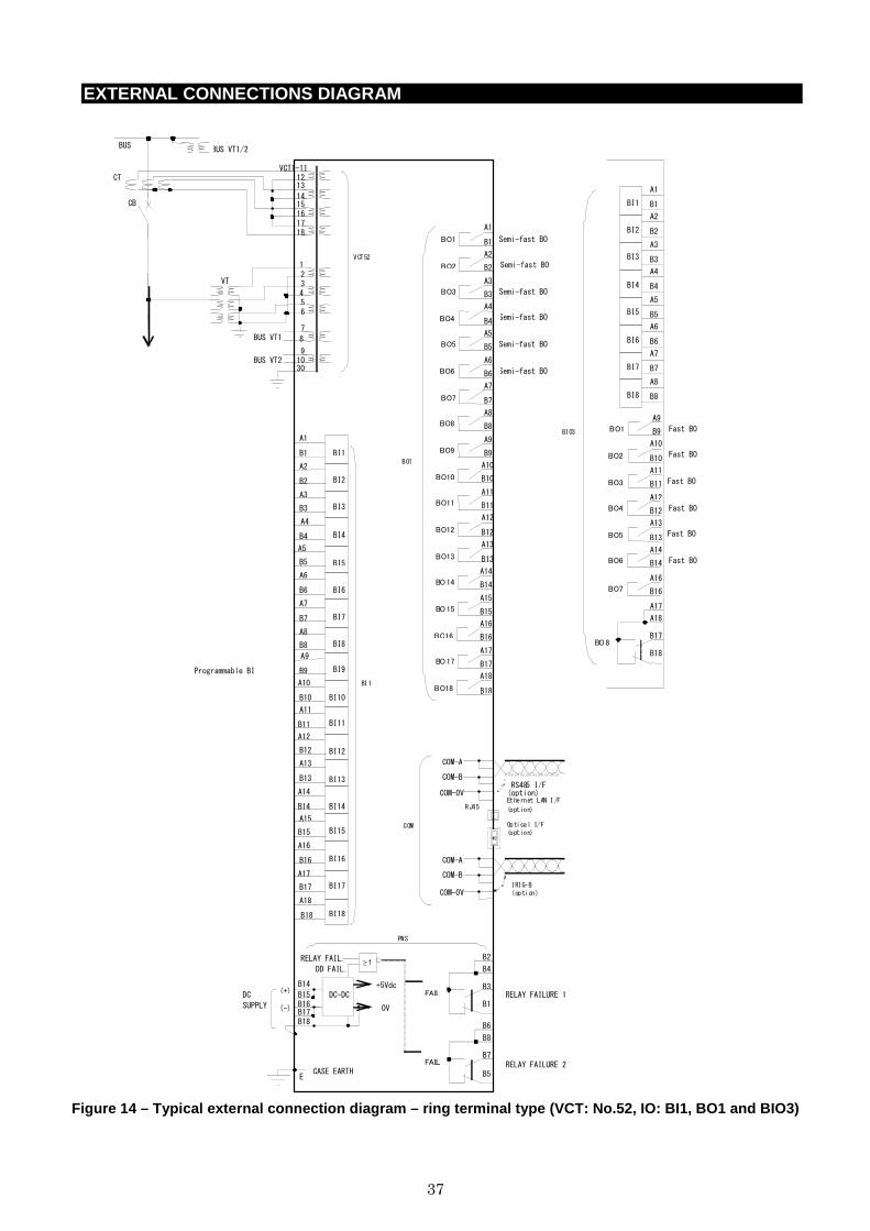
EXTERNAL CONNECTIONS DIAGRAM
Figure 14 – Typical external connection diagram – r ing terminal type (VCT: No.52, IO: BI1, BO1 and BIO 3)
BUS
VCT1-11
14 13
12
17
16
15
18
3
1
5
7
6
8
BUS VT1/2
CT
CB
VT
BUS VT1
9
10
A1
Semi-fast BO
DD FAIL.
B14
(-)
(+) +5Vdc
0V
B18
E
B17
B15
B16
DC
SUPPLY
CASE EARTH
DC-DC
RELAY FAIL.
≥1
BI1
BI10
BI11
BI2
BI8
BI12
BI9
BI5
BI6
BI7
BI3
BI4
BI13
BI14
BI15
BI16
BI17
BI18
30
BI1
VCT52
Programmable BI
Ethernet LAN I/F
(option) RJ45
Optical I/F (option)
2
4
BUS VT2
B1
A2
B2
A3
B3
A4
B4
A11
B11
A12
B12
A13
B13
A14
B14
A15
B15
A16
B16
A17
B17
A18
B18
A9
B9
A10
B10
A5
B5
A6
B6
A7
B7
A8
B8
PWS B2
B1
RELAY FAILURE 1 FAIL
B4
B3
B6
B5 RELAY FAILURE 2
FAIL
B8
B7
RS485 I/F
(option)
COM-B
COM-A
COM-0V
IRIG-B (option)
COM-B
COM-A
COM-0V
COM
Semi-fast BO
Semi-fast BO
Semi-fast BO
Semi-fast BO
A1
B1 BO1
A2
B2 BO2
A3
B3 BO3
A4
B4 BO4
A5
B5 BO5
A6
B6 BO6 Semi-fast BO
A7
B7 BO7
A8
B8 BO8
A9
B9 BO9
A10
B10 BO10
A11
B11 BO11
A12
B12 BO12
A13
B13 BO13
A14
B14 BO14
A15
B15 BO15
A16
B16 BO16
A17
B17 BO17
A18
B18 BO18
BO1
BIO3
A1
BI1 B1
A2
BI2 B2
A3
BI3 B3
A4
BI4 B4
A5
BI5 B5
A6
BI6 B6
A7
BI7 B7
A8
BI8 B8
Fast BO
Fast BO
Fast BO
Fast BO
Fast BO
Fast BO
A9
B9 BO1
A10
B10 BO2
A11
B11 BO3
A12
B12 BO4
A13
B13 BO5
A14
B14 BO6
A16
B16 BO7
A17
B18
BO8
A18
B17

38
©C
opyri
ght
2014 T
oshib
a. A
ll r
ights
res
erved
.
・The information given in this catalog is subject to change without notice. ・The information given in this catalog is as of 20 June 2014. ・The information given in this catalog is presented only as a guide for the
applications of our products. No responsibility is assumed by TOSHIBA for any infringements of patents or other rights of the third parties which may result from its use. No license is granted by implication or otherwise under any patent or patent rights of TOSHIBA or others.
・TOSHIBA products should not be embedded to the downstream products which are prohibited to be produced and sold, under any law and regulations.
- Toshiba does not take any responsibility for incidental damage (including loss of business profit, business interruption, loss of business information and other pecuniary damage) arising out of the use or disability to use the products.
GKP-99-12034 Rev0.10
Social Infrastructure Systems Company 72-34, Horikawa-cho, Saiwai-ku, Kawasaki 212-8585, Japan Tel +81-44-331-1462 Fax +81-44-548-9540 http://www.toshiba-relays.com