Embed Size (px)
Citation preview
TYPICAL APPLICATIONS
• Scooters • Personnel Carriers • Carts • Electric Boats
• Portable Pumps • Lifts • Floor Polishers
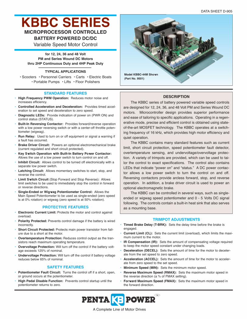
Model KBBC-44M Shown
(Part No. 9501)
DESCRIPTION
The KBBC series of battery powered variable speed controls
are designed for 12, 24, 36, and 48 Volt PM and Series Wound DC
motors. Microcontroller design provides superior performance
and ease of tailoring to specific applications. Operating in a regen-
erative mode, precise and efficient control is obtained using state-
of-the-art MOSFET technology. The KBBC operates at a switch-
ing frequency of 16 kHz, which provides high motor efficiency and
quiet operation.
The KBBC contains many standard features such as current
limit, short circuit protection, speed potentiometer fault detector,
overtemperature sensing, and undervoltage/overvoltage protec-
tion. A variety of trimpots are provided, which can be used to tai-
lor the control to exact specifications. The control also contains
LEDs that indicate “power on” and “status.” A DC power contac-
tor allows a low power switch to turn the control on and off.
Reversing contactors provide arcless forward, stop, and reverse
operation. In addition, a brake driver circuit is used to power an
optional electromagnetic brake.
The KBBC can be controlled in several ways, such as single-
ended or wigwag speed potentiometer and 0 - 5 Volts DC signal
following. The controls contain a built-in heat sink that also serves
as a mounting base.
KBBC SERIESMICROPROCESSOR CONTROLLED
BATTERY POWERED DC/DC
Variable Speed Motor Control
STANDARD FEATURES• High Frequency PWM Operation: Reduces motor noise and
increases efficiency.
• Controlled Acceleration and Deceleration: Provides timed accel-
eration to set speed and deceleration to zero speed.
• Diagnostic LEDs: Provide indication of power on (PWR ON) and
control status (STATUS).
• Built-In Reversing Contactor: Provides forward/reverse operation
with a low power reversing switch or with a center-off throttle poten-
tiometer (wigwag).
• Run Relay: Used to turn on or off equipment or signal a warning if
a fault has occurred.
• Brake Driver Circuit: Powers an optional electromechanical brake
(current regulated and short circuit protected).
• Key Switch Operation with Built-In Battery Power Contactor:Allows the use of a low power switch to turn control on and off.
• Inhibit Circuit: Allows control to be turned off electronically with a
separate low power switch.
• Latching Circuit: Allows momentary switches to start, stop, and
reverse the control.
• Limit Switch Circuit (Stop Forward and Stop Reverse): Allows
limit switches to be used to immediately stop the control in forward
or reverse directions.
• Single-Ended or Wigwag Potentiometer Control: Allows the
Main Speed Potentiometer to be used as single-ended (zero speed
is at 0% rotation) or wigwag (zero speed is at 50% rotation).
DATA SHEET D-905
PROTECTIVE FEATURES
• Electronic Current Limit: Protects the motor and control against
overload.
• Polarity Protected: Prevents control damage if the battery is wired
incorrectly.
• Short Circuit Protected: Protects main power transistor from fail-
ure due to a short at the motor.
• Overtemperature Protection: Reduces control output as the tran-
sistors reach maximum operating temperature.
• Overvoltage Protection: Will turn off the control if the battery volt-
age exceeds 125% of nominal.
• Undervoltage Protection: Will turn off the control if battery voltage
reduces below 65% of nominal.
A Complete Line of Motor Drives
for 12, 24, 36 and 48 Volt
PM and Series Wound DC Motors
thru 2HP Continuous Duty and 4HP Peak Duty
TRIMPOT ADJUSTMENTS
• Timed Brake Delay (T-BRK): Sets the delay time before the brake is
engaged.
• Current Limit (CL): Sets the current limit (overload), which limits the maxi-
mum current to the motor.
• IR Compensation (IR): Sets the amount of compensating voltage required
to keep the motor speed constant under changing loads.
• Deceleration (DECEL): Sets the amount of time for the motor to deceler-
ate from the set speed to zero speed.
• Acceleration (ACCEL): Sets the amount of time for the motor to acceler-
ate from zero speed to the set speed.
• Minimum Speed (MIN): Sets the minimum motor speed.
• Reverse Maximum Speed (RMAX): Sets the maximum motor speed in
the reverse direction (a % of FMAX setting).
• Forward Maximum Speed (FMAX): Sets the maximum motor speed in
the forward direction.
SAFETY FEATURES
• Potentiometer Fault Circuit: Turns the control off if a short, open,
or ground occurs at the potentiometer.
• High Pedal Disable Function: Prevents control startup until the
potentiometer returns to zero.
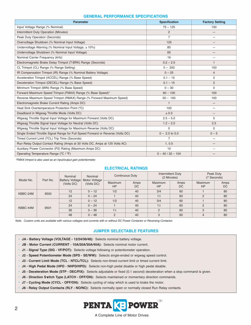
GENERAL PERFORMANCE SPECIFICATIONS
JUMPER SELECTABLE FEATURES
• JA - Battery Voltage (VOLTAGE - 12/24/36/48): Selects nominal battery voltage.
• JB - Motor Current (CURRENT - 10A/20A/30A/40A): Selects nominal motor current.
• J1 - Signal Type (SIG - VF/POT): Selects voltage following or potentiometer operation.
• J2 - Speed Potentiometer Mode (SPD - SE/WW): Selects single-ended or wigwag speed control.
• J3 - Current Limit Mode (TCL - NTCL/TCL): Selects non-timed current limit or timed current limit.
• J4 - High Pedal Mode (HPD - NHPD/HPD): Selects non-high pedal disable or high pedal disable.
• J5 - Deceleration Mode (STP - DEC/FIX): Selects adjustable or fixed (0.1 second) deceleration when a stop command is given.
• J6 - Direction Switch Type (LATCH - OFF/ON): Selects maintained or momentary direction commands.
• J7 - Cycling Mode (CYCL - OFF/ON): Selects cycling of relay which is used to brake the motor.
• J8 - Relay Output Contacts (RLY - NO/NC): Selects normally open or normally closed Run Relay contacts.
*FMAX trimpot is also used as an input/output gain potentiometer.
ELECTRICAL RATINGS
Note: Custom units are available with various voltages and currents with or without DC Power Contactor or Reversing Contactor.
A Complete Line of Motor Drives
2
Parameter Specification Factory Setting
Input Voltage Range (% Nominal) 75 – 125 100
Intermittent Duty Operation (Minutes) 2 —
Peak Duty Operation (Seconds) 7 —
Overvoltage Shutdown (% Nominal Input Voltage) 125 —
Undervoltage Warning (% Nominal Input Voltage, ± 10%) 85 —
Undervoltage Shutdown (% Nominal Input Voltage) 65 —
Nominal Carrier Frequency (kHz) 16 —
Electromagnetic Brake Delay Trimpot (T-BRK) Range (Seconds) 0.2 – 2.5 1
CL Trimpot (CL) Range (% Range Setting) 0 – 200 150
IR Compensation Trimpot (IR) Range (% Nominal Battery Voltage) 0 – 25 4
Acceleration Trimpot (ACCEL) Range (% Base Speed) 0.1 – 15 2
Deceleration Trimpot (DECEL) Range (% Base Speed) 0.1 – 15 2
Minimum Trimpot (MIN) Range (% Base Speed) 0 – 30 0
Forward Maximum Speed Trimpot (FMAX) Range (% Base Speed)* 60 – 100 100
Reverse Maximum Speed Trimpot (RMAX) Range (% Forward Maximum Speed) 50 – 100 100
Electromagnetic Brake Current Rating (Amps DC) 1 —
Heat Sink Overtemperature Protection Point (ºC) 100 —
Deadband in Wigwag Throttle Mode (Volts DC) ± 0.3 —
Wigwag Throttle Signal Input Voltage for Maximum Forward (Volts DC) 2.5 – 5.0 5
Wigwag Throttle Signal Input Voltage for Neutral (Volts DC) 1.2 – 2.5 2.5
Wigwag Throttle Signal Input Voltage for Maximum Reverse (Volts DC) 0 0
Single Ended Throttle Signal Range for Full Speed Forward or Reverse (Volts DC) 0 – 2.5 to 5.0 0 – 5
Timed Current Limit (TCL) Trip Time (Seconds) 7 —
Run Relay Output Contact Rating (Amps at 30 Volts DC, Amps at 125 Volts AC) 1, 0.5 —
Auxiliary Power Connector (P2) Rating (Maximum Amps DC) 10 —
Operating Temperature Range (ºC / ºF) 0 – 40 / 32 – 104 —
Model No. Part No.
Nominal
Battery Voltage
(Volts DC)
Nominal
Motor Voltage
(Volts DC)
Continuous DutyIntermittent Duty
(2 Minutes)
Peak Duty
(7 Seconds)
Maximum
HP
Amps
DC
Maximum
HP
Amps
DC
Maximum
HP
Amps
DC
KBBC-24M 950012 0 – 12 1/2 40 3/4 60 1 80
24 0 – 24 1 40 11⁄2 60 2 80
KBBC-44M 9501
12 0 – 12 1/2 40 3/4 60 1 80
24 0 – 24 1 40 11⁄2 60 2 80
36 0 – 36 11⁄2 40 2 60 3 80
48 0 – 48 2 40 3 60 4 80
P2
M2
M1
10A
CURRENT
JB
40A
30A
20A
5 24 3
P3
PWR
ON
57 6 24 3 1
P1
KBBC B-
B+
J6
LATCHTCLSIG
SE
WW
POT
VF
SPD
HPD
NHPD
TCL
NTCL
HPD STP
FIX
DEC
J1 J2 J3 J4 J5
OFF
ON
OFF
ON
CYCLN
ONC
RLY
J7 J8
ENABLE
P4
STATUS VOLTAGE
JA48
12
24
36
2
1
RELAY
P5
DIRECTION SWITCHES
STOP LIMIT SWITCHES
STOP
RUN FWD
RUN REV
USED FOR3
3
1
2, 3
B+AUXILIARY
POWER
RUN RELAY
OUTPUT
CONTACTS
B-
3
USED FOR ELEC-
TROMAGNETIC
BRAKE
SUPPLIED
(FRONT VIEW)
POTENTIOMETER
MAIN SPEED
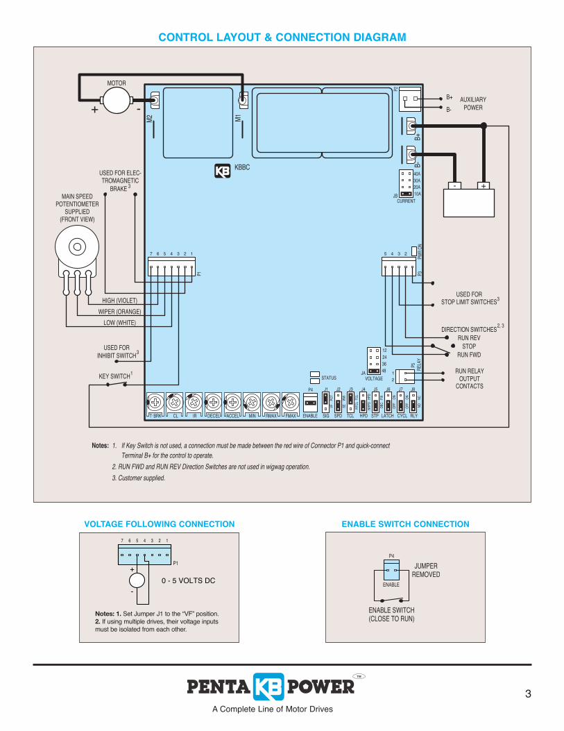
If Key Switch is not used, a connection must be made between the red wire of Connector P1 and quick-connect
Terminal B+ for the control to operate.
2. RUN FWD and RUN REV Direction Switches are not used in wigwag operation.
3. Customer supplied.
Notes:
INHIBIT SWITCH
KEY SWITCH
USED FOR
HIGH (VIOLET)
WIPER (ORANGE)
LOW (WHITE)
BATTERY
+ -
MOTOR
ACCELBRK CL IR DECEL RMAXMIN FMAX.T
1.
- +
CONTROL LAYOUT & CONNECTION DIAGRAM
57 6
0 - 5 VOLTS DC
-
+
P1
24 3 1
(CLOSE TO RUN)ENABLE SWITCH
ENABLE
P4
JUMPERREMOVED
VOLTAGE FOLLOWING CONNECTION ENABLE SWITCH CONNECTION
A Complete Line of Motor Drives
3
Notes: 1. Set Jumper J1 to the “VF” position.
2. If using multiple drives, their voltage inputs
must be isolated from each other.

P2
B-
B+
CURRENT
JB
20A
10A
30A
40A
PWR
ON
P3
45 23
P1
7 56 234 1
KBBC
M2
M1
VOLTAGE
JA48
24
36
12
RELAY
P5
2
1
STATUS
TCLENABLE
P4
SIG
VF
SE
SPD
J1
POT
J2
WW
J7
CYCL
J5
STP
NTCL
NHPD
HPD
J3
TCL
J4
HPD
OFF
DEC
LATCH
J6
FIX ON
OFF
RLY
NO
J8
ON
NC
T.BRK DECEL ACCEL FMAXMINCL IR RMAX
0.26
[6.53]
6.26
[159.11]
[146.05]
5.75
[5.08]TYPICAL (4 PLACES)
(2 PLACES)
0.20
[42.39]1.67
[20.32]0.80
[104.14]4.10
2.50
[63.50]
MECHANICAL SPECIFICATIONS (Inches / [mm])
KB ELECTRONICS, INC.
12095 NW 39th Street, Coral Springs, FL 33065-2516 • (954) 346-4900 • Fax (954) 346-3377
Outside Florida Call TOLL FREE (800) 221-6570 • E-mail – [email protected]
www.kbelectronics.com (A42116) – Rev. A – 5/2010
GREEN AND RED STATUS LEDs
*Flash Rate: Slow = 1 second on / 1 second off. Quick = 0.15 second on / 0.15 second off.
Control Status Green LED Red LED Flash Rate*
Run On Off Slow
Stop On Off Quick
Curent Limit (Warning) Off On Steady
Undervoltage (Warning) On On Slow
Overvoltage/Undervoltage Fault (Shutdown) On On Quick
Overtemperature Fault (Shutdown) On On Slow Alternating
Main Speed Potentiometer Fault (Shutdown) On On Quick Alternating
Motor or Brake Fault (Shutdown) On On Double Quick Alternating
Timed Current Limit (Shudown) Off On Quick


![Zojmdhibkb - Irkutsk State University · 2 JZ[hlZ\uiheg_gZ\eZ[hjZlhjbb jZklbl_evgh -fbdjh[guo \aZbfh^_ckl\bc \ N=;MG Kb[bjkdbc bgklblml nbabheh]bb b [bhobfbb jZkl_gbc Kb[bjkdh]h hl^_e_gbyJhkkbckdhcZdZ^_fbbgZmd](https://img.pdfslide.net/doc/110x75/5ec408277af72d70fc51c403/zojmdhibkb-irkutsk-state-university-2-jzhlzuiheggzezhjzlhjbb-jzklblevgh.jpg)


![todbts ufptsP.S. bc ufyf[kt,ek cfbyajhvfwbj …dspace.nplg.gov.ge/bitstream/1234/32263/1/P.S...lt ,j,blf y uf sf db-c e akt ,bc it vlt u^ vt -hbc vjdf kt j,bc it vc he kt ,t kb jh]t](https://img.pdfslide.net/doc/110x75/5e28e3422709ed648403f72d/todbts-ufptsps-bc-ufyfktek-cfbyajhvfwbj-lt-jblf.jpg)