Embed Size (px)
Citation preview

15-Jul-02 Kit # 1040185 1
BD GOVERNOR SPRING KIT INSTALLATION INSTRUCTIONS
NOTE: Unless this product has been identified with a CARB # it is only legal in California for racing vehicles which may never be used upon a highway
BD ENGINE BRAKE, INC. Unit A10-33733 King Rd, Abbotsford, BC, Canada V2S 7M9
US Shipping: 88-446 Harrison St, Sumas, WA 98295 US Mail: PO Box 231, Sumas, WA 98295 Phone: 604-853-6096 Fax: 604-853-8749 Internet: www.bd-power.com
17-Apr-01 Kit # 1040185 2
INTRODUCTION Thank you for purchasing the BD Governor Spring Kit, this kit is designed and engineered to enhance the middle and high end throttle response and enable more power thru the entire throttle range. TOOL LIST Fender covers to protect paint Hammer to strike punch and hand impact tool 7/16” deep socket, 3/8” drive with 3” ratchet 19mm socket, 3/8” or ½” drive 10mm six point socket, 3/8” drive with extensions Center punch 8 - 10” long Tape or clean towels to cover openings ¼” drive with 3” extensions 7mm and 1/4" six point sockets Hand impact tool, 3/8” or ½” drive 8mm, 6-point 1/4” drive socket Torque wrench capable of at least 30 ft lbs ¼” to 3/8” and/or ½” adapter to hand impact tool Large screwdriver or small pry bar 7/16” open-end wrench RTV silicon sealant 5/8” open-end wrench 8mm Allen wrench Pliers and Pencil magnet Vernier caliper T15 & T20 TORX bits 1/4” drive with 1/4” extension 6” long Large standard screwdriver bit with 6” adapter for impact tool
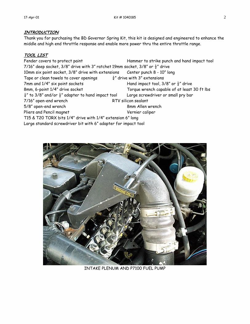
INTAKE PLENUM AND P7100 FUEL PUMP

17-Apr-01 Kit # 1040185 3
INSTALLATION 1. Park vehicle in a suitable work location, set parking brake, place automatic transmissions in park, manual transmissions in neutral, and open hood. 2. Disconnect both negative battery cables. 3. Clean engine if necessary to keep debris and foreign objects from entering engine. 4. Place fender cover or protective covering to protect paint and batteries. 5. Using a 7/16” deep socket, loosen lower clamp on upper intake connection hose and slide lower clamp off of hose and down the steel tube out of the way. (FIGURE 1) 6. Remove the six bolts holding the air intake connection and dipstick tube in place using a 10 mm 6 point socket. NOTE: Observe that these bolts are of different lengths so they can be installed in correct location during assembly. (FIGURE 1)
7. Remove intake manifold connection and hose as a unit, taking care not to damage gasket. This gasket can normally be reused, however if it is torn it will have to be replaced. 8. Cover the air tube and manifold openings with tape or towels to keep foreign objects out. 9. Remove injection pump fuel supply tube banjo bolt using a 19mm socket. NOTE: A few ounces of fuel will drain out which could wash the sealing washers away. Take care NOT to lose sealing washers as they are reused. If lost or damaged replace with Cummins part number 3918192. NOTE: The fuel supply tube is not removed; loosening it on the injection pump end allows access to the AFC housing screws. OPTIONAL: You can avoid removing the banjo bolt if you bend the fuel supply line slightly to make access to the break off screw. This option some times eliminates breaking into the fuel line, and makes engine restart more quickly.

17-Apr-01 Kit # 1040185 4
10. Next remove the front passenger side AFC housing break off screw. NOTE: This screw is a factory break off screw with rounded head and no screwdriver, Allen head or TORX slot. Use a hand impact tool with a 6” long 1/4” extension and a T15 TORX bit to remove this screw. A center punch may be required to start a hole in the center of this screw. Set the hand impact tool in the removal position (counter clockwise) and use light hammer taps on the impact tool to loosen this screw. In some cases the hole in the top of this screw is to large for the T15 bit thus use the T20 TORX bit. There is usually a lock washer and flat washer under each of these screws. OPTIONAL: A sharp chisel can be used to remove the break off screws by the chiseling in a counter-clockwise direction to remove the screw.
11. Mark the position of the AFC housing on the pump then, using a hand impact tool and an 8mm socket, remove the two driver side AFC screws. Then loosen 8mm bolt on the governor cover to free the shut off solenoid. CAUTION: DO NOT DAMAGE THE SHUT OFF LINKAGE 12. Use the hand impact tool with large standard screwdriver bit to remove the rear passenger side AFC screw. 13. Remove the fuel shutdown solenoid bracket from the AFC housing to gain clearance. 14. Lift AFC housing by moving it out of
the way toward the rear of the engine. The boost line need not be disconnected. NOTE: Some engines have a metal boost line instead of a plastic line between the engine intake and AFC housing, in this case the boost line should be disconnected. 15. Scribe mark the position of the torque plate. Remove torque plate screws using a hand impact tool with large screwdriver bit. WARNING: Do not drop anything into the pump opening. Remove torque plate with a magnet or pliers.

17-Apr-01 Kit # 1040185 5
16. Bar (roll) the engine over until the governor spring adjusting nut is just to the left of (below) the rocker strap. 17. Using Vernier calipers, measure the distance from the top of the governor stud to the top of the governor spring adjusting nut. Record this measurement for reassembly. 18. Remove adjusting nut using a long thin screwdriver and a pencil magnet. CAUTION: Do not drop nut. 19. Remove the spring seat and all inner springs (leave large spring in place). Remove inner spring seat at the bottom of the bore and remove any shims that are installed. NOTE: Check for shims stuck to the springs or seats, DO NOT reinstall shims. Spring kit does not require these shims.
17-Apr-01 Kit # 1040185 6
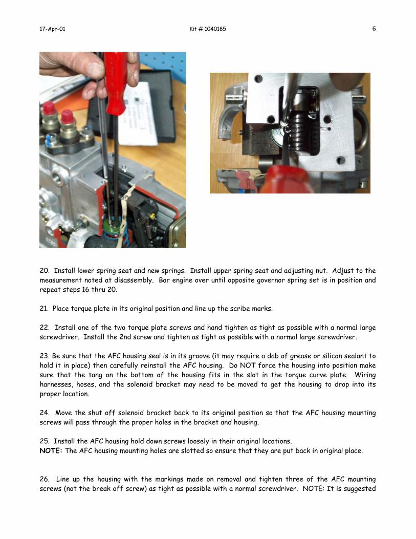
20. Install lower spring seat and new springs. Install upper spring seat and adjusting nut. Adjust to the measurement noted at disassembly. Bar engine over until opposite governor spring set is in position and repeat steps 16 thru 20. 21. Place torque plate in its original position and line up the scribe marks. 22. Install one of the two torque plate screws and hand tighten as tight as possible with a normal large screwdriver. Install the 2nd screw and tighten as tight as possible with a normal large screwdriver. 23. Be sure that the AFC housing seal is in its groove (it may require a dab of grease or silicon sealant to hold it in place) then carefully reinstall the AFC housing. Do NOT force the housing into position make sure that the tang on the bottom of the housing fits in the slot in the torque curve plate. Wiring harnesses, hoses, and the solenoid bracket may need to be moved to get the housing to drop into its proper location. 24. Move the shut off solenoid bracket back to its original position so that the AFC housing mounting screws will pass through the proper holes in the bracket and housing. 25. Install the AFC housing hold down screws loosely in their original locations. NOTE: The AFC housing mounting holes are slotted so ensure that they are put back in original place. 26. Line up the housing with the markings made on removal and tighten three of the AFC mounting screws (not the break off screw) as tight as possible with a normal screwdriver. NOTE: It is suggested

17-Apr-01 Kit # 1040185 7
that you complete the test drive before breaking off the head of the break off screw, only tighten it slightly to keep it from falling out during the test drive. You can reuse the original break off screw by installing with a TORX bit. 27. If your vehicle senses manifold pressure, install the hose onto the barbed fitting and tighten the two hose clamps using a 7 mm socket. NOTE: Reinstall the boost pressure line if it was removed. 28. Install the injection pump fuel supply tube banjo fitting, into the bolt if removed in step 9. Be sure that a sealing washer is placed on both side of the banjo fitting, one between the bolt head and banjo, and the other between the banjo injection pump. Tighten the banjo bolt to 24 lb.-ft using a 19 mm socket and suitable torque wrench. 29. Remove the duct tape or towels from the previously covered openings, reinstall the air connection gadget and the air intake connection, starting with the rubber hose on the air intake tube then rotate the connection into position. 30. Clean debris from threads of air connection bolts, then place a small amount of RTV sealer on the first 3/4 inch of threads, reinstall bolts to their original position and tighten to 18 lb.-ft using a 10mm six-point socket and a suitable torque wrench. 31. Reinstall the lower air connection hose clamp and tighten hand tight, do NOT strip threads on clamp bolt. Check the other seven air circuit clamps at this time to ensure the four hoses and eight clamps are not leaking air. 32. Reconnect battery cables then start engine and check for leaks. Since the fuel drained from the injection pump fuel supply tube, it will take several seconds of cranking before the engine will start. Don’t panic, this is normal. Depress the throttle to about half throttle position and crank engine no more than 30 seconds. Let starter motor cool for 2 minutes before attempting to crank for another 30 seconds. The engine should normally start during the first 10 seconds of cranking. If after four 30-second attempts the engine has not started, check to make sure the fuel shutoff solenoid and shutoff lever are moving when the key is turned from off to run. When engine starts let throttle back to idle position and check for fuel leaks and repair as necessary. Test-drive the vehicle. NOTE: Idle adjustment may be necessary as required.
***CAUTION*** IF YOU INTEND TO OPERATE THE ENGINE OVER 3200 RPM YOU SHOULD REPLACE ENGINE VALVE SPRINGS WITH HEAVY DUTY TYPE. INTAKE VALVE SPRINGS ARE INCLUDED WITH THIS KIT, IF YOU DO NOT HAVE HEAVY DUTY EXHAUST SPRINGS INSTALLED PLEASE CALL BD FOR FURTHER INSTRUCTIONS

15-Jul-02 Kit # 1040185 8
BD ENGINE BRAKE, INC. Unit A10-33733 King Rd, Abbotsford, BC, Canada V2S 7M9
US Shipping: 88-446 Harrison St, Sumas, WA 98295 US Mail: PO Box 231, Sumas, WA 98295 Phone: 604-853-6096 Fax: 604-853-8749 Internet: www.bd-power.com

17-Apr-01 Kit # 1040185 9


![PERFORMANCE OF A GASKETED JOINT UNDER BOLT ......gasketed joints show better sealing performance if bolts in a joint are tightened as per ASME bolt tightening strategy [12] as compared](https://img.pdfslide.net/doc/110x75/6126f377fb6ad86c6c28798c/performance-of-a-gasketed-joint-under-bolt-gasketed-joints-show-better-sealing.jpg)