Embed Size (px)
Citation preview

BDeye combined CCTV video door access system
USER MANUAL

2

3
Contents
What is included and Optional Extras . . . . . . . . . . . . . . . . . . . . . . . . . . . . . . . . . . . . . . 3Description . . . . . . . . . . . . . . . . . . . . . . . . . . . . . . . . . . . . . . . . . . . . . . . . . . . . . . . . . . . . . . 4Installation . . . . . . . . . . . . . . . . . . . . . . . . . . . . . . . . . . . . . . . . . . . . . . . . . . . . . . . . . . . . . . 6Operation . . . . . . . . . . . . . . . . . . . . . . . . . . . . . . . . . . . . . . . . . . . . . . . . . . . . . . . . . . . . . . . . 7Operation Buttons . . . . . . . . . . . . . . . . . . . . . . . . . . . . . . . . . . . . . . . . . . . . . . . . . . . . . . . . 8Setup . . . . . . . . . . . . . . . . . . . . . . . . . . . . . . . . . . . . . . . . . . . . . . . . . . . . . . . . . . . . . . . . . . . . 9Network . . . . . . . . . . . . . . . . . . . . . . . . . . . . . . . . . . . . . . . . . . . . . . . . . . . . . . . . . . . . . . . . 15Video Playback . . . . . . . . . . . . . . . . . . . . . . . . . . . . . . . . . . . . . . . . . . . . . . . . . . . . . . . . . 20Operation Instruction . . . . . . . . . . . . . . . . . . . . . . . . . . . . . . . . . . . . . . . . . . . . . . . . . . . . 21Technical Specification . . . . . . . . . . . . . . . . . . . . . . . . . . . . . . . . . . . . . . . . . . . . . . . . . . 22
Software 500GB Hard Drive User Manual
15m Camera Cable
What is included
VDE Call Point Camera Camera Extension Cable VDE Extension Cable
Optional Extras
Monitor Camera Remote Controller

4
DescriptionMONITOR
2.5" HARD DISK CARTRIDGE
VOICEADJUSTMENT
A/V OUT
IR RECEIVER
POWER SWITCH
LOADSPEAKER
POWERINDICATOR
TOUCHPANEL
MIC
POWERSUPPLY
VDE CALLPOINT 2CAM 1
VDE CALLPOINT 1CAM 2
CAM 3SENSORDEVICE
CAM 4TCP/IP
NETWORK

5
INSERTION OF THE HARD DISK DRIVE
1. Follow the direction marked besidethe button to open the cover of thehard disk cartridge.
2. Insert the hard disk paying attentionto the direction of the slot.
3. Push the hard disk down. 4. Close the cover.

6
POWERSUPPLY
TCP/IP (Network)
12
43
4-Pin connector for video door entry call point (BDeye VDE)
1 – GND (Black) 3 – B+ (Red)2 – Video (Yellow) 4 – Audio (White)
512 3
4
5-Pin connector for alarm device
1 – Alarm Out (Blue) 5 – GND (Black)2 – Alarm In (Brown) 4 – Sensor 1 (Red)
3 – Sensor 2 (White)
65
123 4
6-Pin connector for camera (BDeye Cam)
1 – GND for Video (Black) 6 – Audio In (White)2 – Control (Blue) 5 – Video In (Yellow)3 – GND for Audio & Power (Brown) 4 – VDD (Red)
InstallationWIRING
7
Operation
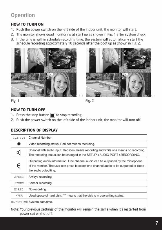
HOW TO TURN ON1. Push the power switch on the left side of the indoor unit, the monitor will start.2. The monitor shows quad monitoring at start up as shown in Fig. 1 after system check.3. If the time is within schedule recording time, the system will automatically start the
schedule recording approximately 10 seconds after the boot up as shown in Fig. 2.
HOW TO TURN OFF1. Press the stop button to stop recording.2. Push the power switch on the left side of the indoor unit, the monitor will turn off.
DESCRIPTION OF DISPLAY
Note: Your previous settings of the monitor will remain the same when it's restarted frompower cut or shut off.
1,2,3,4 Channel Number
Video recording status. Red dot means recording.
Channel with audio input. Red icon means recording and white one means no recording.The recording status can be changed in the SETUP->AUDIO PORT->RECORDING.
Outputting audio information. One channel audio can be outputted by the microphone of the monitor. The user can press to select one channel audio to be outputted or closethe audio outputting.
A?REC Always recording.
S?REC Sensor recording.
N?REC No recording.
*75% Used space of hard disk. "*" means that the disk is in overwriting status.
DATE/TIME System date/time.
2 0 1 0 / 1 0 / 2 1 2 2 : 2 0 : 5 1
1 2
3 4
A?REC *75% 2 0 1 0 / 1 0 / 2 1 2 2 :
1 2
3 4
Fig. 1 Fig. 2

8
Operation buttons
ICON NAME OPERATIONDisplay Full Screen Display of Channel 1/Number 1
Display Full Screen Display of Channel 2/Number 2
Display Full Screen Display of Channel 3/Number 3
Display Full Screen Display of Channel 4/Number 4
Display Quad Display
Setup Enter/Exit Setup
Audio Channel Switch/Close Audio Output
REC Start/Stop Recording
Stop Stop
Play Play/Pause
Move/Confirm Up
Move/Confirm Down
Move/Confirm Left/Backward
Move/Confirm Right/Forward
Move/Confirm Choose/Confirm
Talk/Monitoring Talk/Monitoring/Turn on Monitor Display
Unlock Unlock
Display On/Off Turn On/Off Monitor Display
Note: Buttons on the remote controller are same functions as on monitor buttons, exceptthe (On/Off) on the remote controller.

Press to move the red toselect the channel, then press to set thecamera connected to this channel to be ON or OFF.
9
SetupTo enter SETUP menu, press the stopbutton , then press .The following screen will display:
EEXXIITTMMOOVVEE CCHHOOOOSSEE
SSEETTUUPP
CAMERA ON/OFF
RECORD ON/OFF
COVERT CHANNEL [ OFF ]
AUDIO PORT
RECORDING FRAME RATE
VIDEO QUALITY NORMAL
RECORD SCHEDULE
MOTION DETECTION
ALARM
HARD DISK DRIVE
GENERAL
NETWORK
DEFAULT
CAMERA ON/OFF
RECORD ON/OFF
COVERT CHANNEL [ OFF ]
AUDIO PORT
RECORDING FRAME RATE
VIDEO QUALITY NORMAL
RECORD SCHEDULE
MOTION DETECTION
ALARM
HARD DISK DRIVE
GENERAL
NETWORK
DEFAULT
1 ON 2 ON
3 OFF 4 OFF
EXITMOVE CHOOSE
CAMERA ON/OFF
CAMERA ON/OFFEach channel can be set ON or OFF. If setto OFF, the corresponding screen goesblack and recording function is disabled.Default is ON.
RECORD ON/OFFVideo recording function of each channelcan be enabled or disabled separately. If it isset to OFF, the screen will keep showing thesurveiled scene, but it will not be recorded.
Press to move the red toselect the channel, then press to set thecamera connected to this channel to be ON or OFF.
NO CAM means there is no camera beingconnected with the corresponding channelof the monitor.
11 OONN 22 OONN
33 OOFFFF 44 NNOO CCAAMM
EEXXIITTMMOOVVEE CCHHOOOOSSEE
RECORD ON/OFF
EXITMOVE CHOOSE
SETUP
CAMERA ON/OFF
RECORD ON/OFF
COVERT CHANNEL [ OFF ]
AUDIO PORT
RECORDING FRAME RATE
VIDEO QUALITY NORMAL
RECORD SCHEDULE
MOTION DETECTION
ALARM
HARD DISK DRIVE
GENERAL
NETWORK
DEFAULT
11 OONN 22 OONN
33 OOFFFF 44 OOFFFF
EEXXIITTMMOOVVEE CCHHOOOOSSEE
CAMERA ON/OFF

10
COVERT FUNCTIONYou can choose one channel to be covert.This covert channel will not be shown onthe screen, but it can be recorded.
AUDIO PORTTwo channels of audio input are available.Audio acquisition devices can be connectedto any two video channels. Users can enableor disable recording of audio separately bysetting the RECORDING.
Note: Microphone of the monitor is an audioacquisition device for audio port 1.
Press to move the red tothe channel to be set, then press to setthe recording frame rate of this channel toa proper value.
11 1166 FFPPSS 22 1166 FFPPSS
33 1166 FFPPSS 44 22 FFPPSS
EEXXIITTMMOOVVEE CCHHOOOOSSEE
RECORDING FRAME RATETOTAL 32 FPS
CAMERA ON/OFFFrame rate of each channel can be setseparately to 1,2,3,4,5,6,12,16,25 FPS.Total frame rate of four channels is 50 FPSfor PAL TV system and 60FPS for NTSC TVsystem. For example, if you set 16FPS forchannel 1, channel 2 and channel 3 for amonitor in PAL TV system, you can choose1FPS or 2FPS for channel 4 and keep theselected recording frame rate of otherchannels same, however, if you want to setthe frame rate of channel 4 to a optionmore than 2FPS, the frame rate of otherchannels will be reduced automatically.

11
VIDEO QUALITYThere are three options (HIGH, NORMALand LOW) for video quality of recording.The better recording quality you choose,the more disk space it takes.
MOTION DETECTION
RECORD TIMESet the recording time when a motion eventoccurs in the SENSOR RECORDING mode.
DETECTED CHANNEL / AREA
Users can turn ON or OFF the motiondetection function of each channel. Press or to move the red to selectthe channel, then press to set themotion detection ON or OFF.
Press button to select a preferred videoquality of recording.
RECORDING SCHEDULEUsers can schedule the recording hour byhour for the whole day. The three optionsof recording are as following,
> NO RECORDING: Video from the CCTVcameras will not be recorded.
> ALWAYS RECORDING: Video will alwaysbe recorded.
> SENSOR RECORDING: Video will berecorded when motion is detected or analarm event occurs.
Press to move the red toselect the time frame, then press to setthe recording mode.

12
Press to move the red to the AREA,then press or to select a channel andpress to trigger the motion setting.
ALARM SETUP
VIDEO LOSSIn the monitoring status,if the video cableconnection is not good, the indoor unit willalarm with beep sound. Users can set it ONor OFF.
ALARM DEVICE
Alarm sensor setting: You can connect 2alarm sensors with the monitor and set themto be bonded with 2 of the 4 CCTV channels.If an external alarm sensor is connected andit's triggered by an event, the monitor willalarm with beep sound and also activate therecording if it's in SENSOR RECORDINGschedule. If you have connected with anexternal alarm output device, it will send analarm. Users can also enable or disable theconnected alarm sensors by setting themOPEN or CLOSE.
Alarm Time: It's for setting the time of alarmoutputting when an alarm event occurs. OFFmeans no response to the alarm event andCONT means constantly response to thealarm event till someone stop it manually.
Four sensitivity levels can be selected andthe sensitivity increases with the numberrising. Press to select the grid.Then press to change the sensitivitylevel.
IR TRIGGEROnly human motion can activate therecording in the SENSOR RECORDING modeif IR TRIGGER is set ON. Otherwise allmotion will activate the recording.

13
HARD DISK DRIVE
HDD information
> ST9408221AS: Hard disk model.
> HDD CAPACITY: The capacity of currenthard disk.
> HDD USED: The occupation of hard diskspace, displayed in percentage.
OVERWRITE ENABLED
If it is set to YES, the system willautomatically overwrites the earlierfootage when the storage is full.
FORMAT HDD
Format the current hard disk. Password setin the GENERAL is required for formattingthe hard disk and the initial password is111111 (press 6 times).
GENERAL
To set system-related issues.
DATE/TIME: Set the system time.
Press or to move the red to thedigit which you are going to change, thenpress to change the numbers.
RING: You can choose a preferred ring forvisitors calling. There are total 9 options.
LANGUAGE: Chinese and English areavailable.
TFT-LCD DISPLAY:When it's set to ON, thescreen will be always lighted, and if it's setto OFF, the screen will be turned off innormal, but it will be activated when thereis a call. Users can press to open thescreen display when it's turned off.
TFT-LCD SETTING: Users can adjustBRIGHTNESS, CONTRACT and SATURATIONof the screen display to a proper value.

14
PASSWORD: Users can reset password. Thelength is fixed to 6 digits, stands for 1,stands for 2, stands for 3, stands
for 4. The initial password is 111111 (press 6 times).
Note: You can press to delete when youenter a wrong digit.
ACCESS BY PASSWORD: The user mustenter the password before any furtheroperation. Default setting is OFF.
DEFAULT: The initial password is "111111".The password and network setting will notbe changed after default setting.

15
NetworkBASIC SETTING OF NETWORK
Connect the monitor to the network. Press to enter the SETUP menu. Use and button to select NETWORK, then press to enter the NETWORK menu. The
screen will display as Fig. 33.
MAC ADDRESS: It is a unique identifierassigned to network interfaces forcommunications on the physical networksegment.
IP ALLOCATION: Supports bothDHCP(dynamic) and STATIC IP.
DHCPIP SETTING
If DHCP is selected, IP ADDRESS, SUBNETMASK, GATEWAY and DNS SERVER 1 will beobtained from the DHCP serverautomatically. Users can set the DNSSERVER 2 optionally.
DNS SERVER 2
Press or to move to the digit to beset, then press or to move to thecorresponding digit and press to chooseit. Repeat this step untill the DNS SERVER2 is set correctly.
Note: To guarantee the stability of the IPaddress in the LAN. It's recommended toobtain the IP automatically by DHCP modeand write down your current IP address,then change IP allocation to static andenter IP information in the networksetting.
STATIC IP SETTING
If STATIC IP is selected, users should set IPADDRESS, SUBNET MASK, GATEWAY andDNS SERVER 1 manually. DNS SERVER 2can be set optionally.
IP ADDRESS
Press or to move to the digit to beset, then press or to move to thecorresponding digit and press to chooseit. Repeat this step untill the IP ADDRESSis set correctly.
EEXXIITTMMOOVVEE CCHHOOOOSSEE
NNEETTWWOORRKK
MAC ADDRESS... <00:BB:4B:E8:21:A8>
IP ALLOCATION.. [DHCP]
IP ADDRESS....... <0.0.0.0>
SUBNET MASK... <0.0.0.0>
GATEWAY........... <0.0.0.0>
DNS SERVER 1.. <0.0.0.0>
DNS SERVER 2.. [0.0.0.0]
HTTP PORT........ [ 80] 80,1024-49151
USER SETUP.....
DDNS SETUP.....
MAC ADDRESS... <00:BB:4B:E8:21:A8>
IP ALLOCATION.. [DHCP]
IP ADDRESS....... <0.0.0.0>
SUBNET MASK... <0.0.0.0>
GATEWAY........... <0.0.0.0>
DNS SERVER 1.. <0.0.0.0>
DNS SERVER 2.. [0.0.0.0]
HTTP PORT........ [ 80] 80,1024-49151
USER SETUP.....
DDNS SETUP.....

16
SUBNET MASK
Press or to move to the digit to beset, then press or to move to thecorresponding digit and press to chooseit. Repeat this step untill the SUBNETMASK is set correctly.
GATEWAY
Press or to move to the digit to beset, then press or to move to thecorresponding digit and press to chooseit. Repeat this step untill the GATEWAY isset correctly.
DNS SERVER 1
Press or to move to the digit to beset, then press or to move to thecorresponding digit and press to chooseit. Repeat this step untill the DNS SERVER1 is set correctly.
DNS SERVER 2
Press or to move to the digit to beset, then press or to move to thecorresponding digit and press to chooseit. Repeat this step untill the DNS SERVER2 is set correctly.
Note: Please restart your monitor afternetwork setup.

17
OPEN HTTP PORTIt's necessary to open the HTTP port ofthe monitor before the users can getremote access to it.
Assign a port number to be opened
Optional HTTP PORT is 80,1024 to 49151.
Press or to move to the digit to beset, then press or to move to the corresponding digit and press to chooseit. Repeat this step untill the HTTP PORT isset correctly. The default port is 80.
Open the HTTP PORT on a router
It might be done in different way to openan HTTP PORT on different types ofrouters. For a specific router, pleasecontact the vendor to get the detail.
Remote monitoring and control
1. Open an IE browser, enter the monitor'sIP address such ashttp://192.168.18.101:6666 in the LANor your WAN IP such ashttp://113.110.152.49:6666 in theaddress bar. First visit will be promptedto install plugin, select "Yes" to install it.Installation will begin automaticallyafter downloading. If the plugin does notdownload automatically, please click"Download" in "If the plugin can notdownload, click here". Double click thedownloaded file to install it when thedownload is finished.
Note: The port number can be omitted ifyou use the default port 80, forexample http://192.168.18.101.
2. After the plug-in installation, it will pop-up a "Remote Client" window as shownbelow. If not, please close and restart IEthen input the network address correctly.
3. If the remote client does not show themonitored scene, please lower thesecurity level of your browser. OpenInternet Explorer browser, select "Tools"- "Internet Options" - "Security" -"Internet" - "Custom Level". In the popupwindow, open all theActiveX plugins andcontrols.
4. Click to enlarge the previewscreen two times.
A?REC *75% 2 0 1 0 / 1 0 / 2 1 2 2 :
1 2
3 4
18
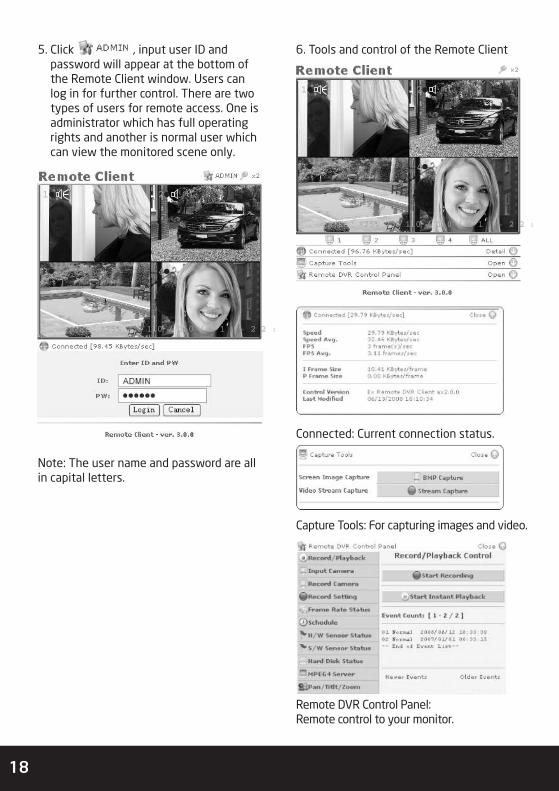
5. Click , input user ID andpassword will appear at the bottom ofthe Remote Client window. Users canlog in for further control. There are twotypes of users for remote access. One isadministrator which has full operatingrights and another is normal user whichcan view the monitored scene only.
Note: The user name and password are allin capital letters.
A?REC *75% 2 0 1 0 / 1 0 / 2 1 2 2 :
1 2
3 4
6. Tools and control of the Remote Client
Connected: Current connection status.
Capture Tools: For capturing images and video.
Remote DVR Control Panel:Remote control to your monitor.
A?REC *75% 2 0 1 0 / 1 0 / 2 1 2 2 :
1 2
3 4

19
DDNS setup
To setup Dynamic Domain Name Service.The user is required to register and createa host name from the DDNS serviceprovider WWW.DYNDNS.COM. Then enteruser ID(user name), password and domainname obtained in the DDNS SETUP of themonitor.
1. Visit website http:// www.dyndns.com.
2. Sign up an account and create a hostname such as ‘remoteview. dyndns -free. Com’.
3. DDNS Setup in the monitorEnter the host name, Username andPassword you obtained from the DDNSservice provider in the DOMAIN NAME,USER ID and PASSWORD of the DDNSSETUP menu as shown below.
4. Enter http: //remoteview. dyndns -free. com: 6666 in your browser to getremote access to your monitor.
A?REC *75% 2 0 1 0 / 1 0 / 2 1 2 2 :
1 2
3 4
20
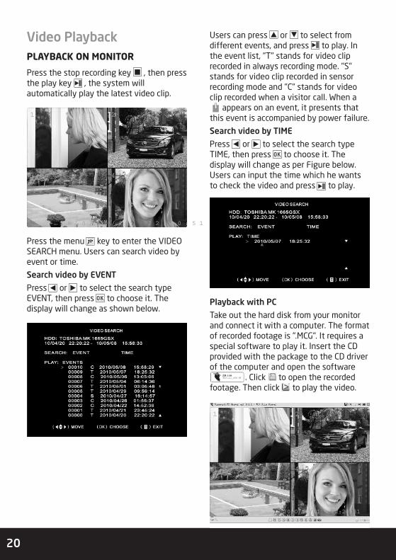
Video PlaybackPLAYBACK ON MONITOR
Press the stop recording key , then pressthe play key , the system willautomatically play the latest video clip.
Press the menu key to enter the VIDEOSEARCH menu. Users can search video byevent or time.
Search video by EVENT
Press or to select the search typeEVENT, then press to choose it. Thedisplay will change as shown below.
Users can press or to select fromdifferent events, and press to play. Inthe event list, "T" stands for video cliprecorded in always recording mode. "S"stands for video clip recorded in sensorrecording mode and "C" stands for videoclip recorded when a visitor call. When a
appears on an event, it presents thatthis event is accompanied by power failure.
Search video by TIME
Press or to select the search typeTIME, then press to choose it. Thedisplay will change as per Figure below.Users can input the time which he wantsto check the video and press to play.
Playback with PC
Take out the hard disk from your monitorand connect it with a computer. The formatof recorded footage is ".MCG". It requires aspecial software to play it. Insert the CDprovided with the package to the CD driverof the computer and open the software
. Click to open the recordedfootage. Then click to play the video.
2 0 1 0 / 1 0 / 2 1 2 2 : 2 0 : 5 1
1 2
3 4
2010/10/21 22:20:51
1 2
3 4

21
Operation instruction
MCG file dump
Always Top Window
50% Screen
100% Screen
150% Screen
Close
Open another MCG file
Jump back 60 Sec
Jump back 10 Sec
Switching storage device
Preferences - Change the application's default setting
Audio Output Setting / Volume control
Drag the window by its part below title bar to move it
Reverse Playback
Pause
Forward Playback
Jump forward 10 Sec
Jump forward 60 Sec
Play frame by frame backward
Play frame by frame forward
Record
Capture [BMP]
Move thewindow
22
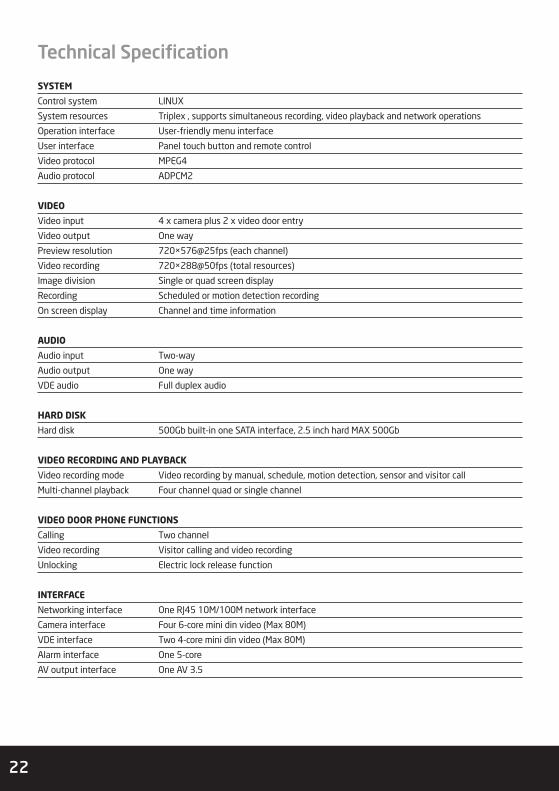
SYSTEM
Control system LINUX
System resources Triplex , supports simultaneous recording, video playback and network operations
Operation interface User-friendly menu interface
User interface Panel touch button and remote control
Video protocol MPEG4
Audio protocol ADPCM2
VIDEO
Video input 4 x camera plus 2 x video door entry
Video output One way
Preview resolution 720×576@25fps (each channel)
Video recording 720×288@50fps (total resources)
Image division Single or quad screen display
Recording Scheduled or motion detection recording
On screen display Channel and time information
AUDIO
Audio input Two-way
Audio output One way
VDE audio Full duplex audio
HARD DISK
Hard disk 500Gb built-in one SATA interface, 2.5 inch hard MAX 500Gb
VIDEO RECORDING AND PLAYBACK
Video recording mode Video recording by manual, schedule, motion detection, sensor and visitor call
Multi-channel playback Four channel quad or single channel
VIDEO DOOR PHONE FUNCTIONS
Calling Two channel
Video recording Visitor calling and video recording
Unlocking Electric lock release function
INTERFACE
Networking interface One RJ45 10M/100M network interface
Camera interface Four 6-core mini din video (Max 80M)
VDE interface Two 4-core mini din video (Max 80M)
Alarm interface One 5-core
AV output interface One AV 3.5
Technical Specification

23
POWER SUPPLY
Video call point Four way camera powered by integral central power supply
Outdoor station Two way outdoor station powered by integral central power supply
SPECIFICATIONS
Power supply DC +12V 4.5A
Screen 8” TFT-LCD
Resolution 800x600
Temperature Range -10ºc – +70ºc
Dimensions 250 × 210 × 35mm
Installation methods Desktop or wall mounting options
CAMERA
Sensor 1/3" LG CCD
Effective Pixel 500(H)×582(V)Resolution Ratio 720x576
Frame PAL: 1-25 fps
Electronic shutter speed 1/60 – 1/100,000 S(NTSC)Horizontal resolution 420TVL
Lens 3.6MM
IR viewing distance 10m
Power supply DC 12V
Operation Current 220mA
Operation Temperature Indoor/outdoor, -10ºc – 60ºc
Weatherproofing IP55 rated

Technical Support 01527 515145
Elite Security ProductsUnit 7, Target Park, Shawbank RdLakeside, Redditch B98 8YN
Telephone: 01527 515150Technical Support: 01527 515145
email: [email protected]