Embed Size (px)
Citation preview
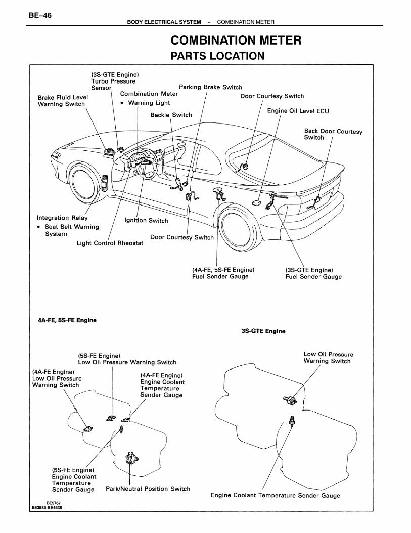
COMBINATION METERPARTS LOCATION
−BODY ELECTRICAL SYSTEM COMBINATION METERBE−46

GroundHeadlight Dimmer and Turn Signal Switch, and HazardWarning SwitchFuel Sender Gauge−terminal 3GroundECMGAUGE FuseECT Pattern Select Switch(A/T) Park/Neutral Position Switch(M/T) Starter RelayHeadlight Dimmer and Turn Signal Switch, and HazardWarning SwitchHeadlight Dimmer and Turn Signal Switch, andHeadlight LO (LH)
Brake Fluid Level Warning Switch−terminal 1, andParking Brake SwitchIgniterDOME FuseDoor Courtesy SwitchIntegration Relay−terminal 4Low Oil Pressure Warning SwitchAlternator−terminal “L”IGN FuseTaillight Control Relay
Light Control Rheostat−terminal 3Cruise Control ECUECMO/D OFF SwitchGroundEngine Coolant Temperature Sender GaugeECU−B FuseAirbag ECUABS ECUFuel Sender Gauge−terminal 1
METER CIRCUIT(4A−FE, 5S−FE Engine)
12
3567910
11
12
Wiring connector sideNo.
1
234568910
12345678910
−BODY ELECTRICAL SYSTEM COMBINATION METERBE−47

GroundHeadlight Dimmer and Turn Signal Switch, and HazardWarning SwitchFuel Sender Gauge−terminal 3Turbo Pressure sensor−terminal 2GroundECMGAUGE FuseStarter SwitchHeadlight Dimmer and Turn Signal Switch, and HazardWarning SwitchHeadlight Dimmer and Turn Signal Switch, andHeadlight LO (LH)
Brake Fluid Level Warning Switch−terminal 1, andParking Brake SwitchIgniterDOME FuseDoor Courtesy SwitchIntegration Relay−terminal 4Low Oil Pressure Warning SwitchAlternator−terminal “L”IGN FuseTAIL Fuse
Light Control Rheostat−terminal 3Cruise Control ECUECMGroundEngine Coolant Temperature Sender GaugeECU−B FuseAirbag ECUABS ECUFuel Sender Gauge−terminal 2
(3S−GTE Engine)
Wiring connector sideNo.
12
345671011
12
1
234568910
1235678910
−BODY ELECTRICAL SYSTEM COMBINATION METERBE−48

TROUBLESHOOTINGThe table below will be useful for you in troubleshooting these electrical problems. The most likelycauses of the malfunction are shown in the order of their probability. Inspect each part in the ordershown, and replace the part when it is found to be faulty.
* Tachometer, Fuel Gauge, Fuel Level Warning Light, Engine Coolant Temperature Gauge, Voltmeter,Low Oil Pressure Warning Light, Brake Warning Light, Seat Belt Warning Light, ABS Warning Light,Check Engine Warning Light, Cruise Control Indicator Light, O/D OFF Indicator Light and Turbo Meter
1. Bulb2. Brake Fluid Level Warning Switch3. Parking Brake Switch4. Wire Harness
1. Bulb2. Low Oil Pressure Warning Switch3. Wire Harness
1. DOME Fuse2. Bulb3. Door Courtesy Switch4. Wire Harness
1. Bulb2. Buckle Switch3. Integration Relay4. Wire Harness
Engine coolant temperature gauge doesnot operate
Low oil pressure warning light does notlight up
* Gauges and indicator lights do notoperate
1. Bulb2. Light Control Switch3. Wire Harness
1. No. 1 Vehicle Speed Sensor2. Speedometer
1. Receiver Gauge2. Sender Gauge3. Wire Harness
1. Receiver Gauge2. Sender Gauge3. Wire Harness
1. Bulb2. Warning Switch3. Wire Harness
Open door warning light does not light up
Fuel level warning light does not light up
Seat belt warning light does not light up
Meter illumination lights do not light up
Brake warning light does not light up
1. GAUGE Fuse2. Wire Harness
Speedometer does not operate
1. Tachometer2. Wire Harness
Fuel gauge does not operate
Tachometer does not operate
−BE−3BE−60 −
−BE−56BE−56 −
−BE−57BE−57 −
BE−55BE−55 −
BE−51BE−52 −
−BE−54 −
−BE−20 −
−BE−56 −
Parts name
BE−50BE−50
See page
BE−51 −
Trouble
BE−3 −
−BODY ELECTRICAL SYSTEM COMBINATION METERBE−49

SPEEDOMETERSPEEDOMETER INSPECTION (ON−VEHICLE)(a) Using a speedometer tester, inspect the speedometer
for allowable indication error and check the operation ofthe odometer.
HINT: Tire wear and tire over or under inflation willincrease the indication error.If error is excessive, replace the speedometer.(b) Check the speedometer for pointer vibration and
abnormal noise.HINT: Pointer vibration can be caused by a loosespeedometer cable.
NO. 1 VEHICLE SPEED SENSORNO. 1 VEHICLE SPEED SENSOR INSPECTIONCheck that there is continuity between terminals A andB four times per each revolution of the speedometershaft.If operation is not as specified, replace the speedometer.
18 − 2340 − 446 0 − 64.580 − 85100 − 105120 − 125.5140 − 146160 − 167180 − 188200 − 209220 − 230240 − 251
1. Turbo Meter2. Turbo Pressure3. Turbo Meter Drive Circuit4. Wire Harness
19 − 223 9 − 42.559.5 − 63.579.5 − 84100 − 105120 − 125.5140 − 146
20406080100120140160180200220240
Turbo meter does not operate
20406080100120140
BE−58BE−58BE−59 −
Allowable range
Allowable range
Standardindication
Standardindication
Parts name See pageTrouble
(km/h)
(mph)
−BODY ELECTRICAL SYSTEM COMBINATION METERBE−50

TACHOMETERTACHOMETER INSPECTION (ON−VEHICLE)(a) Connect a tune−up test tachometer, and start the
engine.NOTICE:• Reversing the connection of the tachometer will
damage the transistors and diodes inside.
• When removing or installing the tachometer, becareful not to drop or subject to heavy shocks.
(b) Compare the tester and tachometer indications.If error is excessive, replace the tachometer.
(c) Connect terminal 3 and 4 on the wire harness sideconnector through a 3.4 W test bulb.
(d) Turn the ignition switch ON, check that the bulb lightsup and receiver gauge needle moves toward the fullside.HINT: Because of the silicon oil in the gauge, it willtake a short time for the needle to stabilize.If operation is as specified, replace the sender gauge.Then, recheck the system.If operation is not as specified, measure the receivergauge resistance.
FUEL GAUGE SYSTEMFUEL RECEIVER GAUGE INSPECTIONOPERATION(a) Disconnect the connector from the sender gauge.(b) Turn the ignition switch ON, check that the receiver
gauge needle indicates EMPTY.
610 − 7502,800 − 3,2004,800 − 5,2006,700 − 7,300
DC 13.5 V, 25�C (77�F)
7003,0005,0007,000
Allowable rangeStandardindication
rpm
−BODY ELECTRICAL SYSTEM COMBINATION METERBE−51

FUEL SENDER GAUGE INSPECTIONOPERATION(a) Connect a series of three 1.5 V dry cell batteries.
(b) Connect the positive (+) lead from the dry cell batteriesto terminal 3 through a 3.4 W test bulb and the negative(−) lead to terminal 4.
(e) Check that the voltage rises between terminal 3 and 4as the float is moved from the top to bottom position.
If resistance value is not as specified, replace thereceiver gauge.
RESISTANCE Measure the resistance between terminals.
Approx. 101Approx. 252Approx. 151
Approx. 86Approx. 275Approx. 189
4A−FE, 5S−FE EngineBetweenterminals 3S−GTE Engine
Resistance (�)
A−BA−CB−C
−BODY ELECTRICAL SYSTEM COMBINATION METERBE−52

FUEL LEVEL WARNING SYSTEMFUEL LEVEL WARNING LIGHT INSPECTION(4A−FE, 5S−FE Engine)(a) Disconnect the connector from the sender gauge.(b) Connect terminals 1 and 4 on the wire harness sideconnector.(c) Turn the ignition switch ON, check that the warninglight lights up.If the warning light does not light up, test the bulb.
(3S−GTE Engine)(d) Disconnect the connector from the sender gauge.(e) Connect terminals 2 and 4 on the wire harness side
connector.(f) Turn the ignition switch ON, check that the warning
light lights up.If the warning light does not light up, test the bulb.
RESISTANCEMeasure the resistance between terminals 3 and 4 foreach float position.
If resistance value is not as specified, replace thesender gauge.
Approx. 97.1 (3.823)Approx. 272.4 (10.724)
Approx. 45.0 (1.772)Approx. 158.5 (6.240)
Float position mm (in.)
Approx. 3Approx. 110
Resistance (�)
FWD 4WD4WDFWD
−BODY ELECTRICAL SYSTEM COMBINATION METERBE−53

FUEL LEVEL WARNING SWITCH INSPECTION(4A−FE, 5S−FE Engine)(a) Apply battery positive voltage between terminals 1 and
4 through a 3.4 W test bulb, check that the bulb lightsup.HINT: It will take a short time for the bulb to light up.
(3S−GTE Engine)(a) Apply battery positive voltage between terminals 2 and
4 through a 3.4 W test bulb, check that the bulb lightsup.HINT: It will take a short time for the bulb to light up.
(b) Submerge the switch in fuel, check that the bulb goesout.If operation is not as specified, replace the sendergauge.
(b) Submerge the switch in fuel, check that the bulb goesout.If operation is not as specified, replace the sendergauge.
−BODY ELECTRICAL SYSTEM COMBINATION METERBE−54

(c) Ground terminal on the wire harness side connectorthrough a 3.4 W test bulb.
(d) Turn the ignition switch 4N, check that the bulb lightsup and receiver gauge needle moves toward the hotside.If operation is as specified, replace the sender gauge.Then, recheck the system.If operation is not as specified, measure the receivergauge resistance.
ENGINE COOLANT TEMPERATURE GAUGESYSTEMENGINE COOLANT TEMPERATURE RECEIVER GAUGEINSPECTIONOPERATION(a) Disconnect the connector from the sender gauge.(b) Turn the ignition switch ON, check that the receiver
gauge needle indicates COOL.
RESISTANCEMeasure the resistance between terminals.HINT: Connect the test leads so that the current fromthe ohmmeter can flow according to the chart order.
If resistance value is not as specified, replace thesender gauge.
Approx. 182Approx. 131Approx. 51
Betweenterminals
Resistance (�)
A → BA → CB → C
−BODY ELECTRICAL SYSTEM COMBINATION METERBE−55

BRAKE WARNING SYSTEMBRAKE WARNING LIGHT INSPECTION(a) Disconnect the connectors from the brake fluid level
warning switch and parking brake switch.(b) Connect terminals on the wire harness side of the level
warning switch connector.(c) Turn the ignition switch ON, check that the warning
light lights up.If the warning light does not light up, test the bulb.
BRAKE FLUID LEVEL WARNING SWITCH INSPECTION(a) Check that there is no continuity between terminals
with the switch OFF (float up).(b) Check that there is continuity between terminals with
the switch ON (float down).If operation is not as specified, replace the switch.
LOW OIL PRESSURE WARNING SWITCH INSPECTION(a) Check that there is continuity between terminal and
ground with the engine stopped.(b) Check that there is no continuity between terminal and
ground with the engine running.HINT: Oil pressure should be over 29 kPa (0.3 kgf/cm2,4.3 psi).If operation is not as specified, replace the switch.
LOW OIL PRESSURE WARNING SYSTEMLOW OIL PRESSURE WARNING LIGHT INSPECTION(a) Disconnect the connector from the warning switch and
ground terminal on the wire harness side connector.(b) Turn the ignition switch ON, check that the warning
light lights up.If the warning light does not light up, test the bulb.
PARKING BRAKE SWITCH INSPECTION(a) Check that there is continuity between terminals with
the switch ON (switch pin released).(b) Check that there is no continuity between terminals
with the switch OFF (switch pin pushed in).
−BODY ELECTRICAL SYSTEM COMBINATION METERBE−56

SEAT BELT BUCKLE SWITCH INSPECTION(a) Check that there is continuity between terminals on the
switch side connector with the switch ON (beltfastened).
(b) Check that there is no continuity between terminals onthe switch side connector with the switch OFF (beltunfastened).If operation is not as specified, replace the seat beltinner.
SEAT BELT WARNING SYSTEMSEAT BELT WARNING LIGHT SYSTEM(a) Remove the integration relay from the junction block.(b) Ground terminal 4 on the junction block side connector.(c) Turn the ignition switch ON, check that the warning
light lights up.If the warning lights does not light up, test the bulb.
INTEGRATION RELAY INSPECTIONRELAY CIRCUITRemove the integration relay from the junction blockand inspect the connector on the junction side as shownin the chart.
If circuit is as specified, replace the relay.
Battery positivevoltage
Battery positivevoltage
Battery positivevoltage
Ignition switchposition
Ignition switchposition
Buckle switchposition
OFF (belt unfastened)
ON (belt fastened)
Tester connection Specified value
No continuity
LOCK or ACC
LOCK or ACC
No voltage
No voltage
12 − Ground
Continuity
ContinuityContinuity
6 − Ground
3 − Ground
5 − Ground
4 − Ground
ConditionCheck for
Constant
Constant
Voltage
−BODY ELECTRICAL SYSTEM COMBINATION METERBE−57

TURBO PRESSURE SENSOR INSPECTION(a) Connect a series of three 1.5 V dry cell batteries.(b) Connect the positive (+) lead from the dry cell batteries
to terminal 3 and the negative¿−) lead to terminal 1.(c) Connect the positive (+) lead from the voltmeter to
terminal 2 and the negative (−) lead to terminal 1.(d) Check that the voltage between terminals 2 and 1.
Voltage: Approx. 2.4 V
TURBO METER SYSTEMTURBO METER INSPECTIONOPERATION(a) Disconnect the connector from the pressure sensor.(b) Turn the ignition switch ON. Check that the meter
needle moves to upper position.
RESISTANCEMeasure the resistance between terminals A and B.Resistance: Approx. 72�If resistance value is not as specified, replace the turbometer.
(c) Ground terminal 2 on the wire harness side.Check that the meter needle moves to lower position.If operation is not as specified, inspect the turbo meterdrive circuit and resistance.
(e) Apply 26.7 kPa (200 mrnHg, 7.87 in.Hg) of vacuum.Check that the voltage drops below approximately 2.4 V.
−BODY ELECTRICAL SYSTEM COMBINATION METERBE−58

TURBO METER DRIVE CIRCUIT INSPECTION(a) Disconnect the connector from the turbo pressure
sensor.(b) Remove the combination meter with connected three
connectors.(c) Inspect the connector on the wire harness side and
terminals of the turbo meter drive circuit as shown inthe chart.
(f) Using SST, apply 4.9 kPa 10.5 kgf/cm2, 7.1 psi ofpressure.Check that the voltage rises approximately 2.4 V.SST 09992−00241If operations are not as specified, replace the sensor.
If circuit is as specified, replace the drive circuit.
Battery positivevoltage
Battery positivevoltage
Ignition switchposition
Ignition switchposition
Tester connection Specified value
LOCK or ACC
LOCK or ACC No voltage
No voltage
Continuity
Continuity
Continuity
ContinuityContinuity
D − Ground
3 − Ground
1− Ground
E − Ground
ConditionCheck for
Constant
Constant
Constant
Constant
Voltage
A−B
C−2
−BODY ELECTRICAL SYSTEM COMBINATION METERBE−59

METER ILLUMINATION CONTROL SYSTEMLIGHT CONTROL RHEOSTAT INSPECTION(a) Connect terminals 1 and 3 through a 3.4 watts test bulb.(b) Connect the positive (+) lead from the battery to
terminal 1 and the negative (−) lead to terminal 2.(e) Turn the rheostat knob to fully counterclockwise, check
that the test bulb goes out.(d) Gradually turn the rheostat knob to clockwise, check
that the test bulb brightness changes from dark tobright.If operation is not as specified, replace the rheostat.
BULB CHECK SYSTEMBULB CHECK RELAY INSPECTION(a) Connect the positive (+) lead from the battery to
terminal C through a 1.4 W test bulb and the negative (−) lead to terminal B, check that the test bulb does notlight up.
(b) Connect the positive (+) lead from the battery toterminal A, check that the test bulb lights up.If operation is not as specified, replace the relay.
OPEN DOOR WARNING SYSTEMOPEN DOOR WARNING LIGHT INSPECTION(a) Disconnect the connector from the door courtesy switch
and ground terminal on the wire harness side connector.(b) Turn the ignition switch ON, check that the warning
light lights up.If the warning does not light up, test the bulb.
COURTESY SWITCH INSPECTION(a) Check that there is continuity between terminal and theswitch body with the switch ON (switch pin released).(b) Check that there is no continuity between terminal andthe switch body with the switch OFF (switch pin pushedin).If operation is not as specified, replace the switch.
−BODY ELECTRICAL SYSTEM COMBINATION METERBE−60


![Cutler-Hammer · Cutler-Hammer January 2001 Vol. 1, Ref. No. [0177] Group Metering & Meter Breakers Meter Breakers Meter Breakers — Residential Combination Service Entrance Devices](https://img.pdfslide.net/doc/110x75/5f0b858e7e708231d430ede1/cutler-hammer-cutler-hammer-january-2001-vol-1-ref-no-0177-group-metering.jpg)