Embed Size (px)
Citation preview

BE1-GPS100
UHQ-68-02P. O. BOX 269 HIGHLAND, ILLINOIS, U.S.A. 62249 PHONE 618-654-2341 FAX 618-654-2351
BE1-GPS100GENERATORPROTECTION
SYSTEM
The BE1-GPS100 is a multifunction, programmable numerical protection, meter, and controlrelay. Functions provided include three phase voltage controlled, voltage restrained, orstandard overcurrent, phase residual and independent ground overcurrent, negative sequenceovercurrent, breaker failure, over/underfrequency, phase over/undervoltage, zero sequenceover/undervoltage, and negative sequence overvoltage, forward or reverse power, loss ofexcitation, volts per hertz, sync check, sensitive third harmonic ground fault monitoring, breakermonitoring and control and metering functions, all in an integrated system.
ADVANTAGES� BESTlogic provides the user with very high flexibility in configuring a protection and control
system.� Substantial functionality in a small package, useful where space is very limited but high
functionality is needed.� Programmable LCD display allows the relay to replace local indication and control func-
tions, such as panel metering, alarm annunciation, and control switches.� Three independent communication ports with protocol support allows integration with
distributed control systems.� Provides optional separate ground current input for those applications where this is
required.� Includes frequency tracking and voltage restrained overcurrent for backup and cogenera-
tion applications.� Includes Real Time Clock with 8 hour capacitor ride through and optional battery backup.� Available in fully drawout half rack case. Two Basler Electric half rack IEDs (Intelligent
Electronic Devices) can be dovetailed together to mount in a standard 19-inch equipmentrack with no special mounting hardware.
� Available in fully drawout S1 case with test paddle. The S1 case, with available adapterplates, fits cutout, drilling and behind panel projection dimensions for common BaslerElectric, GE and Westinghouse unit case relays.
FEATURESPages 2 and 3
APPLICATIONSPage 3
FUNCTIONALDESCRIPTION
Pages 4 - 6
BESTlogicPages 8 and 9
SPECIFICATIONSPages 7, 10 - 11
ORDERINGINFORMATION
Page 12INSTRUCTION MANUAL MODBUS INSTRUCTION MANUAL
Request publication 9318700990 Request publication 9318700991TIMING CURVES DNP 3.0 INSTRUCTION MANUAL
Request publication 9252000999 Request publication 9318700992
ADDITIONAL INFORMATION
WINDOWS® SOFTWAREInterface for setting and communicating with Basler protection products.Request BESTCOMS for BE1-GPS100.
BE1-GPS100
2
FEATURES
PROTECTION� Phase and Neutral Instantaneous Overcurrent
elements with settable time delay: 50TP, 50TN� Phase, Neutral, and Negative Sequence Time
Overcurrent elements: 46, 51P, 51N, 151N� Phase overcurrent element (51P) includes capabil-
ity of voltage restraint or voltage control.� Internally calculated phase residual, 3I0, available
on all relays. Optional independent ground inputavailable. Neutral overcurrent elements (50TN, 51N,151N) monitor either ground or calculated residual.
� Negative sequence overcurrent element (46)includes algorithm for timing based on generatorK factors or may use standard TOC curves.
� All U.S. and IEC timing curves plus user program-mable curve.
� Phase Undervoltage and Overvoltage elements:27P, 127P, 59P, 159P. Elements use a 1 of 3, 2 of3, or 3 of 3 logic, and monitor either line-line or line-ground voltages.
� Auxiliary Undervoltage and Overvoltage elements:27X, 127X, 59X, 159X. Elements monitor eitherfundamental or third harmonic on the optionalauxiliary 4th VT input, or fundamental phaseresidual, 3V0, of the phase inputs.
� Negative Sequence Overvoltage element: 47� Overexcitation, Volts per Hertz element: 24� Four Under/Overfrequency elements: 81, 181, 281,
381� Forward/Reverse Power: 32, 132� Loss of Excitation (offset sloped VAR flow algo-
rithm): 40Q, 140Q� Breaker Failure protection function: BF� 4 general purpose logic timers: 62, 162, 262, 362� Inadvertent energization protection using 50
elements supervised by 81 and/or 27 elements� 100% stator ground fault protection using auxiliary
voltage elements for ground overvoltage and 3rdharmonic ground undervoltage
� Sync check and/or dead bus close supervision25, 27X (Requires optional 4th VT sensing circuit)
� Programmable Logic using BESTlogic� Two protection settings group controllable via relay
logic, 43 Aux switches, and hardwired inputs.Setting group selection may control tripping logic.
� Fuse loss detection (60FL) protects against falsetrip due to loss of voltage sensing.
CONTROL� Virtual breaker control switch�controllable from
both HMI and com. ports: 101� Four virtual selector switches�controllable from
both HMI and com. ports: 43, 143, 243, 343� Communication port control of 101 and #43
switches allows for SCADA control of relay andbreaker.
INSTRUMENTATION� Real time A, B, C phase current, voltage; fre-
quency; and derived neutral and negativesequence current and voltage.
� Real Time 3 phase Watts, VARs, and PowerFactor.
REPORTS� Current demands for phase, ground, and negative
sequence currents, and forward and reverse Wattsand VARs�magnitudes and time stamps arerecorded for today's peak, yesterday's peak,and peak since reset.
� kWh and kVARh, forward and reverse� Breaker operations counter and contact
interruption duty. Breaker operate time alsoavailable.
FAULT RECORDING� 255 event sequence of events report with I/O and
alarm sub-reports� Fault Reporting; 1 or 2 oscillography records per
fault report� 16 fault summary reports; two most recent Fault
Summary Records saved to non-volative memory� Total number of fault and oscillography records
settable from 6 to 16� Total of 240 cycles oscillography memory @ 12
samples/cycle� COMTRADE format
COMMUNICATION PORTS� Three independent general purpose communica-
tion ports- Front RS-232 ASCII communications- Rear RS-232 ASCII communications- Rear RS-485 ASCII, Modbus, DNP3.0, and TNP protocols
� IRIG-B time sync (unmodulated)
SELF TEST AND ALARM FUNCTIONS� Relay fail, major alarm, and minor alarm LEDs,
and fail-safe alarm output contact.� Extensive internal diagnostics monitor all internal
functions of the relay.� More than 20 additional alarm points�
programmable for major or minor priorityincluding:- User defined logic state alarms that may be
associated with any user specified relay logicstate or relay protective element status.
- Phase current, and forward and reverse Watt andVAR demand alarm.
- Neutral and negative sequence unbalancedemand alarms.

BE1-GPS100
3
APPLICATIONS
The BE1-GPS100 Generator Protection System provides three phase, ground, and negative sequence overcurrent,voltage, frequency, reverse power, loss of excitation, volts per hertz, and sync check protection and is intended foruse in any generator protection application. Its unique capabilities make it ideally suited for applications with thefollowing requirements:� Applications that require the flexibility provided by wide setting ranges, multiple setting groups, multiple coordi-
nation curves, and an extremely versatile programmable logic, in one unit.� Applications that require the economy and space savings provided by a multifunction unit. This one unit can
provide all of the protection, control, metering, and local and remote indication functions required in manytypical units.
� Retrofit applications requiring the features and functions of the GPS-100 in an S1 case.� Applications where the small size and limited behind-panel projection facilitates modernizing protection,
metering, and control systems in existing substations.� Applications that wish to have the protection redundancy provided by having differential relaying in an indepen-
dent protective relaying package.� Applications that require communications and protocol support.� Applications where drawout construction is desirable.� Applications that require high accuracy across a wide frequency range.� Applications where the capabilities of intelligent electronic devices (IEDs) are used to decrease relay and
equipment maintenance costs.
FEATURES, continued
Figure 1 - Advanced HMI (Human Machine Interface)
- Three breaker alarm points programmable forslow trip, interruption duty threshold, oroperations counter.
- Trip circuit voltage and continuity monitor.
PROGRAMMABLE I/O� Four programmable inputs.� Five programmable outputs and one dedicated
programmable alarm output.
HARDWARE FEATURES� Two case configurations
- S1: Basler/GE style (with test plug)- H1: Half Rack
� Active CT technology for low burden andincreased dynamic range.
� Flash Memory for upgrading embeddedprogramming without changing chips.
� Real Time Clock with 8 hour capacitor ride throughand optional battery backup.
� Integral HMI with 2x16 character display andkeypad for editing settings and resetting targetsand alarms.
� Wide range ac/dc power supply options providelong hold up time to ride through dips on powersource. (100 ms with 4 output relays energized,upon complete loss of source. Starting voltage125Vac for Option 1 (48/125Vac/dc) and 250Vacfor Option 2 (125/250Vac/dc))
� Automatically adjusts sampling rate for sensed linefrequency over the range of 10-75 Hz to providehigh accuracy of protective elements over a wideoperating range.
BE1-GPS100
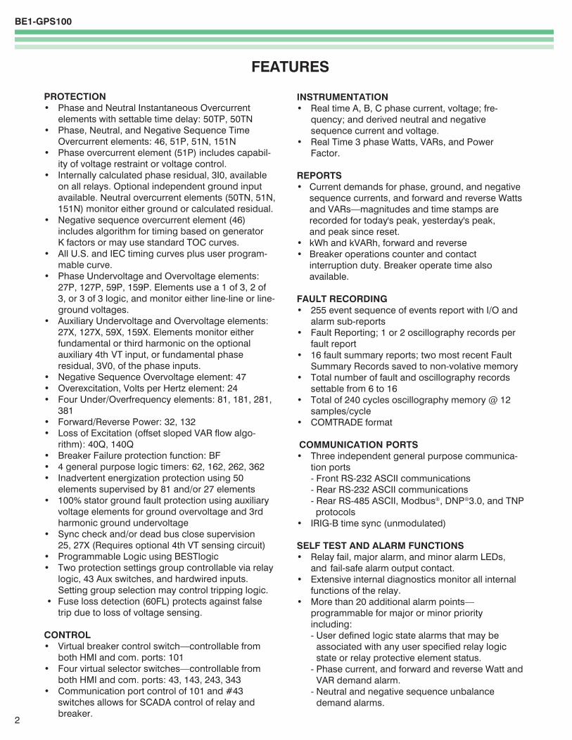
Figure 2A - Typical Alternate Connections for Vx and IG4
FUNCTIONAL DESCRIPTIONThe BE1-GPS100 is a multifunction, numerical relaythat provides a comprehensive mix of protectivefunctions to detect generator faults and abnormaloperating conditions along with control and meteringfunctions in an integrated system. This system issuitable for any generator application and many utility/cogeneration facility intertie applications. Twelvesample per cycle digital signal processing, with fre-quency compensation, extracts the fundamentalcomponent for high accuracy with distorted waveformsand at off-nominal frequency operation.
The unit has one set of three phase current and voltagesensing inputs to provide all common protectivefunctions except generator differential, 87G (which,provided as a separate relay, prevents the "all youreggs in one basket" pitfall). The voltage sensingcircuits automatically configure themselves internallyfor 1 phase, 3 phase 3 wire, or 3 phase 4 wire VTcircuits. An optional 4th auxiliary voltage input isavailable for either generator ground sensing or busvoltage sensing.
The BE1-GPS100 can also be ordered with an optionalindependent ground current input, typically used forapplication with a separate ground CT such as a fluxbalancing window CT or to provide ground backupprotection for the generator step up transformer.
The S1 and half rack cases are fully drawout withcurrent circuit shorting provisions. Two Basler Electrichalf rack IEDs (Intelligent Electronic Devices) such asprimary and backup BE1-GPS100s or the BE1-851 or -951 Overcurrent Protection Systems can be dovetailedtogether to mount in a standard 19" equipment rackwith no special mounting hardware. Replacing anobsolete GE or Westinghouse single function relay witha GPS-100 in an S1 case upgrades existing protectionand monitoring without having to cut the panel.
Three independent communications ports, along withbuilt-in support for Modbus and other commonprotocols, provide easy access to integrating theprotection, control, metering, and status monitoringfunctions into a substation automation system. The
standard IRIG-B port provides time synchronizationfrom a master clock.
Real time metering provides Watt, Watt-hour, VAR,VAR-hour, voltage, amp, and unbalance loadingtelemetry for the protected circuit. Contact sensinginputs and alarm monitoring functions provide realtime status information. Remote control is provided byvirtual control and selector switches with select-before-operate control of programmable outputs.
BESTlogicBESTlogic programmable logic provides the user withhigh flexibility in configuring a protection and controlsystem.
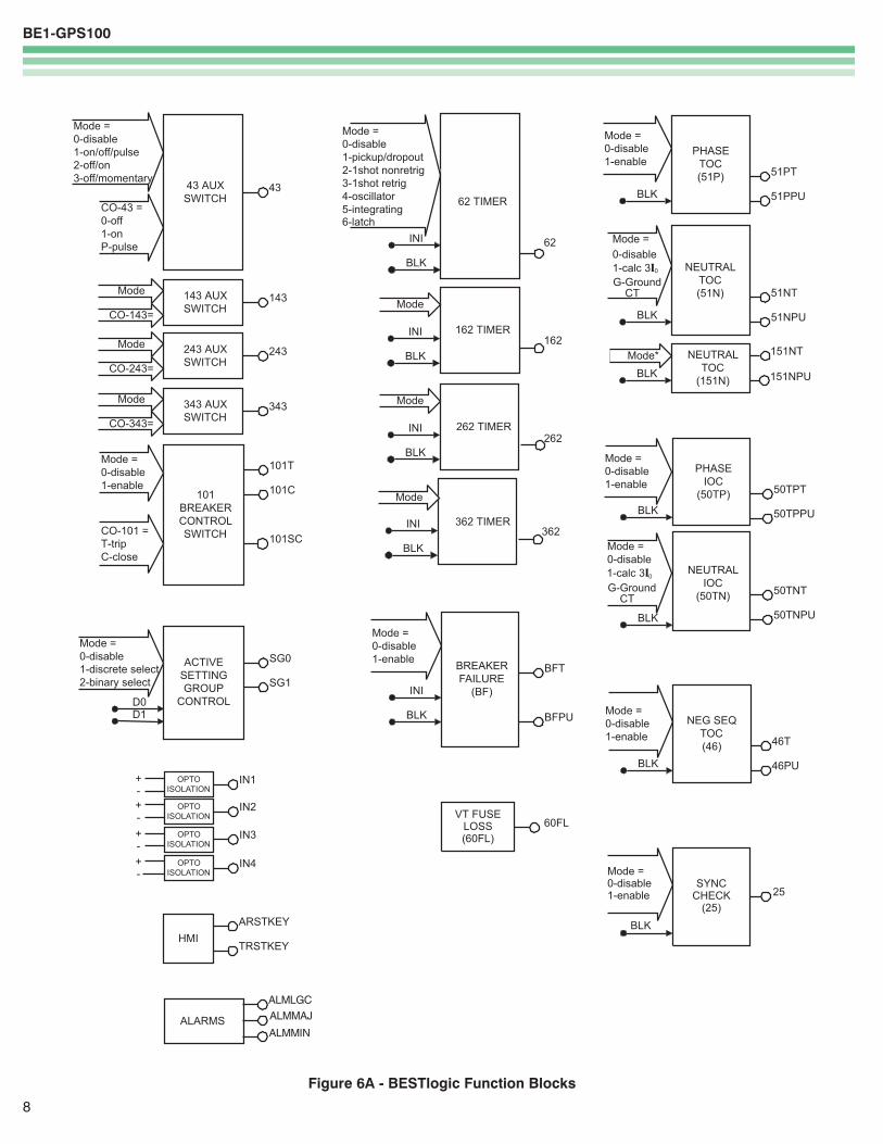
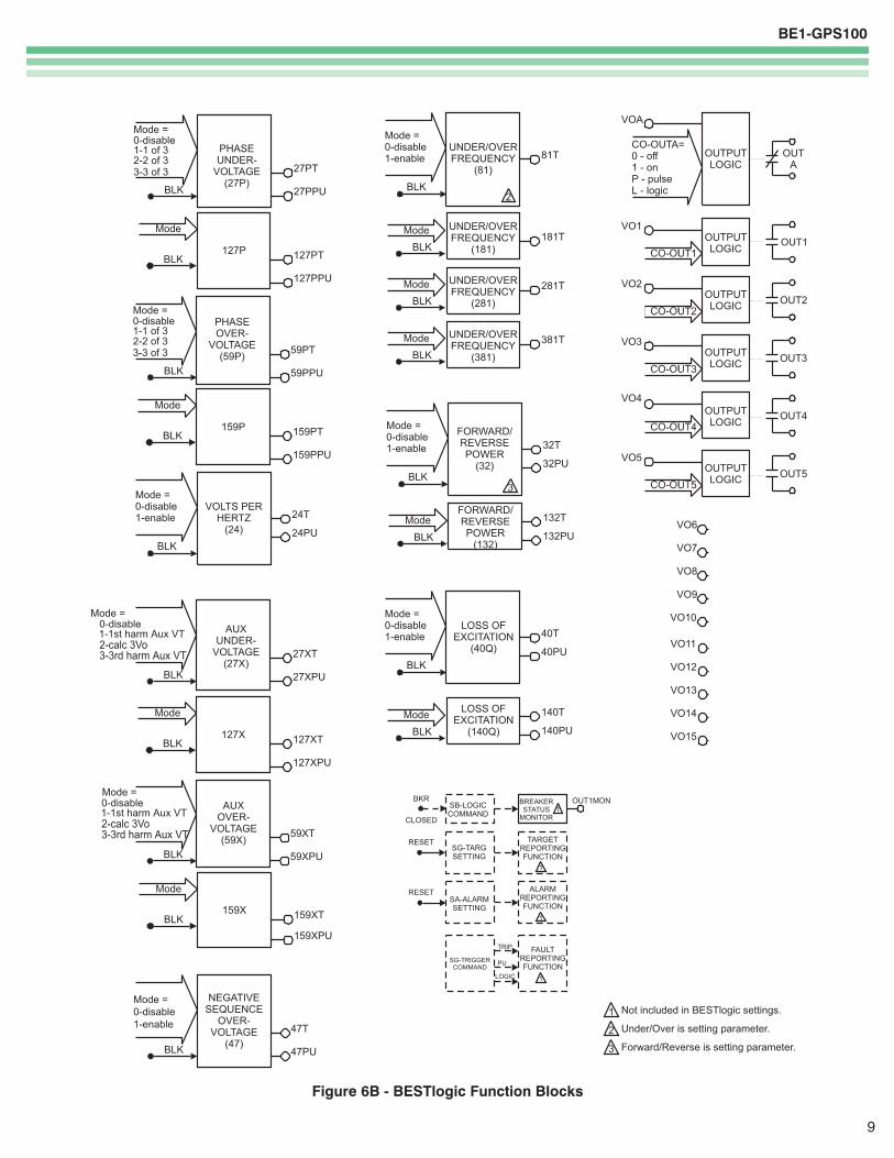
Each of the protection and control functions in theBE1-GPS100 is implemented as an independentfunction block that is equivalent to its single function,discrete device counterpart. Each independent func-tion block has all of the inputs and outputs that thediscrete component counterpart might have. Figures5A and 5B show each of the independent functionblocks available for use in the BE1-GPS100 and theirassociated logic I/O. Programming BESTlogic isequivalent to choosing the devices required by yourprotection and control scheme and drawing schematicdiagrams to connect the logic inputs and outputs toobtain the desired operational logic.
The BE1-GPS100 relay can store, as user settings, oneuser programmable, custom logic scheme. To saveyou time and provide guidance, preprogrammed logicschemes have also been provided. Any of thepreprogrammed schemes can be copied into the logicsettings, then modified to the application's needs.User-programmable variable and virtual switch namesmake relay event reports user-friendly.
BESTlogic provides the protection engineer with theflexibility to set up this powerful multifunction systemwith the same freedom that was once enjoyed withsingle function, discrete devices. It is no longer neces-sary to compromise your standard protection andoperating practices to work within the limitations inprogrammability of previous multifunction devices.
BE1-GPS100
5
FUNCTIONAL DESCRIPTION, continued
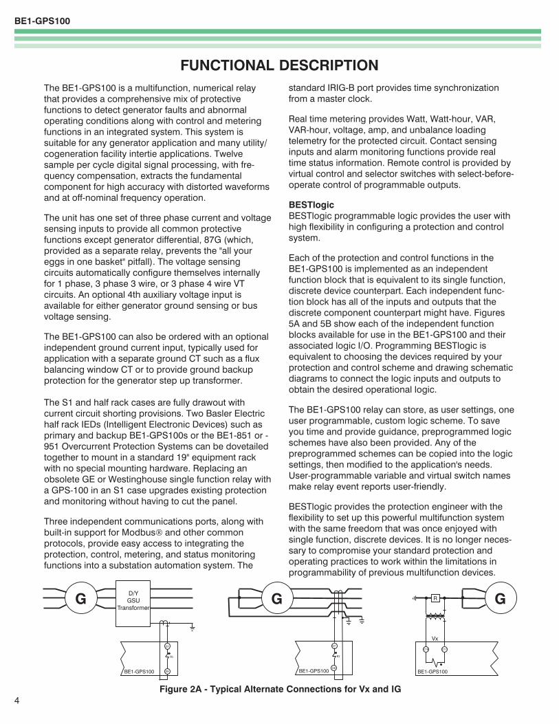
Figure 2B - Typical External Sensing Connections, with Vx and IG Used for Stator Ground Fault
Figure 2C - Typical External Sensing Connections, with Vx Used for Sync Checkand IG Used for Ground Differential Overcurrent
Figure 3 - Typical External Connections
BE1-GPS100
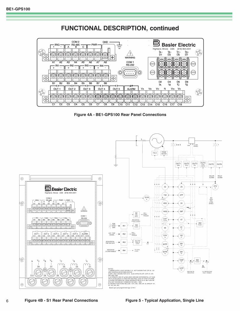
Figure 4A - BE1-GPS100 Rear Panel Connections
6
FUNCTIONAL DESCRIPTION, continued
Figure 5 - Typical Application, Single LineFigure 4B - S1 Rear Panel Connections
BE1-GPS100
7
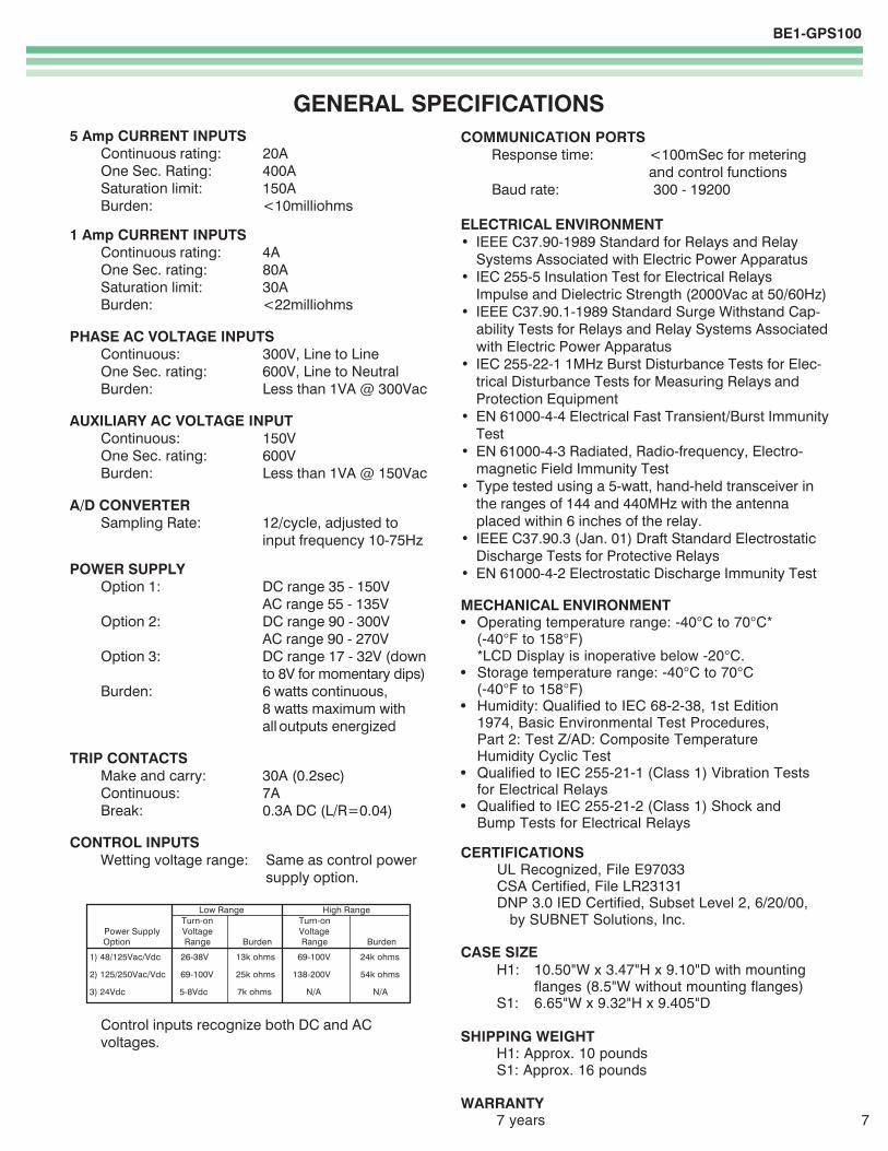
GENERAL SPECIFICATIONS5 Amp CURRENT INPUTS
Continuous rating: 20AOne Sec. Rating: 400ASaturation limit: 150ABurden: <10milliohms
1 Amp CURRENT INPUTSContinuous rating: 4AOne Sec. rating: 80ASaturation limit: 30ABurden: <22milliohms
PHASE AC VOLTAGE INPUTSContinuous: 300V, Line to LineOne Sec. rating: 600V, Line to NeutralBurden: Less than 1VA @ 300Vac
AUXILIARY AC VOLTAGE INPUTContinuous: 150VOne Sec. rating: 600VBurden: Less than 1VA @ 150Vac
A/D CONVERTERSampling Rate: 12/cycle, adjusted to
input frequency 10-75Hz
POWER SUPPLYOption 1: DC range 35 - 150V
AC range 55 - 135VOption 2: DC range 90 - 300V
AC range 90 - 270VOption 3: DC range 17 - 32V (down
to 8V for momentary dips)Burden: 6 watts continuous,
8 watts maximum withall outputs energized
TRIP CONTACTSMake and carry: 30A (0.2sec)Continuous: 7ABreak: 0.3A DC (L/R=0.04)
CONTROL INPUTSWetting voltage range: Same as control power
supply option.
Low Range High Range Turn-on Turn-on
Power Supply Voltage Voltage Option Range Burden Range Burden
1) 48/125Vac/Vdc 26-38V 13k ohms 69-100V 24k ohms
2) 125/250Vac/Vdc 69-100V 25k ohms 138-200V 54k ohms
3) 24Vdc 5-8Vdc 7k ohms N/A N/A
Control inputs recognize both DC and ACvoltages.
COMMUNICATION PORTSResponse time: <100mSec for metering
and control functionsBaud rate: 300 - 19200
ELECTRICAL ENVIRONMENT� IEEE C37.90-1989 Standard for Relays and Relay
Systems Associated with Electric Power Apparatus� IEC 255-5 Insulation Test for Electrical Relays
Impulse and Dielectric Strength (2000Vac at 50/60Hz)� IEEE C37.90.1-1989 Standard Surge Withstand Cap-
ability Tests for Relays and Relay Systems Associatedwith Electric Power Apparatus
� IEC 255-22-1 1MHz Burst Disturbance Tests for Elec-trical Disturbance Tests for Measuring Relays andProtection Equipment
� EN 61000-4-4 Electrical Fast Transient/Burst ImmunityTest
� EN 61000-4-3 Radiated, Radio-frequency, Electro-magnetic Field Immunity Test
� Type tested using a 5-watt, hand-held transceiver inthe ranges of 144 and 440MHz with the antennaplaced within 6 inches of the relay.
� IEEE C37.90.3 (Jan. 01) Draft Standard ElectrostaticDischarge Tests for Protective Relays
� EN 61000-4-2 Electrostatic Discharge Immunity Test
MECHANICAL ENVIRONMENT• Operating temperature range: -40°C to 70°C*
(-40°F to 158°F)*LCD Display is inoperative below -20°C.
• Storage temperature range: -40°C to 70°C(-40°F to 158°F)
• Humidity: Qualified to IEC 68-2-38, 1st Edition1974, Basic Environmental Test Procedures,Part 2: Test Z/AD: Composite TemperatureHumidity Cyclic Test
• Qualified to IEC 255-21-1 (Class 1) Vibration Testsfor Electrical Relays
• Qualified to IEC 255-21-2 (Class 1) Shock andBump Tests for Electrical Relays
CERTIFICATIONSUL Recognized, File E97033CSA Certified, File LR23131DNP 3.0 IED Certified, Subset Level 2, 6/20/00, by SUBNET Solutions, Inc.
CASE SIZEH1: 10.50"W x 3.47"H x 9.10"D with mounting
flanges (8.5"W without mounting flanges)S1: 6.65"W x 9.32"H x 9.405"D
SHIPPING WEIGHTH1: Approx. 10 poundsS1: Approx. 16 pounds
WARRANTY7 years
BE1-GPS100
8
Figure 6A - BESTlogic Function Blocks
BE1-GPS100
9
Figure 6B - BESTlogic Function Blocks
BE1-GPS100
10
PERFORMANCE SPECIFICATIONS
INSTANTANEOUS OVERCURRENT WITHSETTABLE DELAY (50TP, 50TN)
Pickup: 5A CT 0.5 - 150.0A1A CT 0.1 - 30.0A
PU time with TD=0.000 Sec2 cyc for P&G @ 5 x PU3 cyc for N&Q @ 5 x PU
Delay time: 0.000 - 60 secTime Accuracy: ±0.5% or ±½ cyc for P & N
±0.5% or ±1 cyc for Q
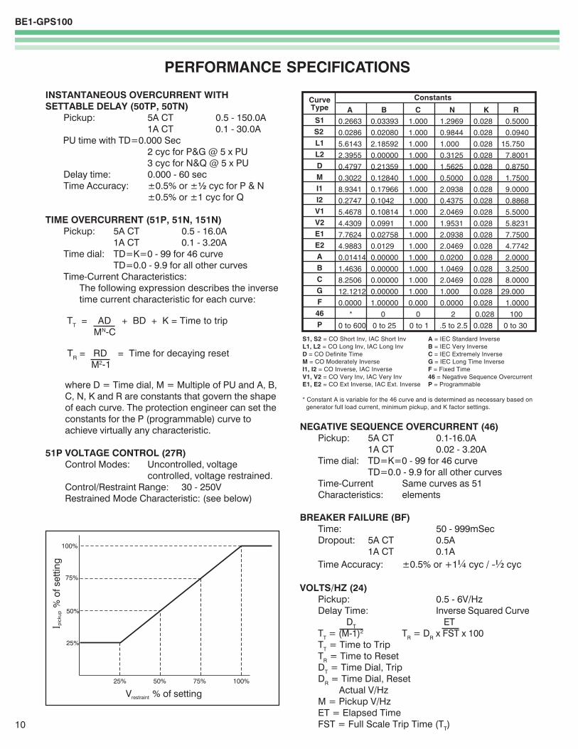
TIME OVERCURRENT (51P, 51N, 151N)Pickup: 5A CT 0.5 - 16.0A
1A CT 0.1 - 3.20ATime dial: TD=K=0 - 99 for 46 curve
TD=0.0 - 9.9 for all other curvesTime-Current Characteristics:
The following expression describes the inversetime current characteristic for each curve:
TT = AD + BD + K = Time to trip
MN-C
TR = RD = Time for decaying reset
M2-1
where D = Time dial, M = Multiple of PU and A, B,C, N, K and R are constants that govern the shapeof each curve. The protection engineer can set theconstants for the P (programmable) curve toachieve virtually any characteristic.
51P VOLTAGE CONTROL (27R)Control Modes: Uncontrolled, voltage
controlled, voltage restrained.Control/Restraint Range: 30 - 250VRestrained Mode Characteristic: (see below)
ConstantsCurveType
S1
S2
L1
L2
D
M
I1
I2
V1
V2
E1
E2
A
B
C
G
F
46
P
A B C N K R
0.2663 0.03393 1.000 1.2969 0.028 0.5000
0.0286 0.02080 1.000 0.9844 0.028 0.0940
5.6143 2.18592 1.000 1.000 0.028 15.750
2.3955 0.00000 1.000 0.3125 0.028 7.8001
0.4797 0.21359 1.000 1.5625 0.028 0.8750
0.3022 0.12840 1.000 0.5000 0.028 1.7500
8.9341 0.17966 1.000 2.0938 0.028 9.0000
0.2747 0.1042 1.000 0.4375 0.028 0.8868
5.4678 0.10814 1.000 2.0469 0.028 5.5000
4.4309 0.0991 1.000 1.9531 0.028 5.8231
7.7624 0.02758 1.000 2.0938 0.028 7.7500
4.9883 0.0129 1.000 2.0469 0.028 4.7742
0.01414 0.00000 1.000 0.0200 0.028 2.0000
1.4636 0.00000 1.000 1.0469 0.028 3.2500
8.2506 0.00000 1.000 2.0469 0.028 8.0000
12.1212 0.00000 1.000 1.000 0.028 29.000
0.0000 1.00000 0.000 0.0000 0.028 1.0000
* 0 0 2 0.028 100
0 to 600 0 to 25 0 to 1 .5 to 2.5 0.028 0 to 30
S1, S2 = CO Short Inv, IAC Short Inv A = IEC Standard InverseL1, L2 = CO Long Inv, IAC Long Inv B = IEC Very InverseD = CO Definite Time C = IEC Extremely InverseM = CO Moderately Inverse G = IEC Long Time InverseI1, I2 = CO Inverse, IAC Inverse F = Fixed TimeV1, V2 = CO Very Inv, IAC Very Inv 46 = Negative Sequence OvercurrentE1, E2 = CO Ext Inverse, IAC Ext. Inverse P = Programmable
* Constant A is variable for the 46 curve and is determined as necessary based on generator full load current, minimum pickup, and K factor settings.
NEGATIVE SEQUENCE OVERCURRENT (46)Pickup: 5A CT 0.1-16.0A
1A CT 0.02 - 3.20ATime dial: TD=K=0 - 99 for 46 curve
TD=0.0 - 9.9 for all other curvesTime-Current Same curves as 51Characteristics: elements
BREAKER FAILURE (BF)Time: 50 - 999mSecDropout: 5A CT 0.5A
1A CT 0.1ATime Accuracy: ±0.5% or +1¼ cyc / -½ cyc
VOLTS/HZ (24)Pickup: 0.5 - 6V/HzDelay Time: Inverse Squared Curve
DT ETTT = (M-1)2 TR = DR x FST x 100TT = Time to TripTR = Time to ResetDT = Time Dial, TripDR = Time Dial, Reset
Actual V/HzM = Pickup V/HzET = Elapsed TimeFST = Full Scale Trip Time (TT)
BE1-GPS100
11
SYNC CHECK (25)Delta Phase Angle: 1 - 25 degreesDelta Voltage Magnitude: 1 - 20VDelta Frequency: 0.01 - 0.50Hz
PHASE OVER/UNDERVOLTAGE(27P, 127P, 59P, 159P)
Mode: 1 of 3; 2 of 3; 3 of 3Pickup: 10.0-300VL-L or 10.0-300VL-NDelay Time: 0.050 - 600sec.
NEGATIVE SEQUENCE OVERVOLTAGE (47)Pickup: 1.0 - 300VL-NDelay Time: 0.050 - 600sec.
AUXILIARY / 3V0 OVER/UNDERVOLTAGE(27X, 127X, 59X, 159X)
Mode: Fundamental VX, Phase 3V0,3rd Harmonic VX
Pickup: 1.0 - 150VDelay Time: 0.050 - 600 Sec.
FREQUENCY (81, 181, 281, 381)Mode: Over, UnderPickup: 40.00 - 70.00 HzDelay Time: 0.000 - 600 Sec.Time Accuracy: ±0.5% or +1 cyc / -0 cyc(Min. trip time affected by minimum 3 cycsecurity count)
POWER (32, 132)Mode: Forward, ReversePickup: 5A: 1.0 - 6000 Watts, 3 ph
1A: 1.0 - 1200 Watts, 3 phPickup Accuracy: ±3%Delay Time: 0.050 - 600 Sec.
UNDEREXCITATION (40Q, 140Q)Pickup: 5A: 1.0 - 6000 VARs, 3 ph
1A: 1.0 - 1200 VARs, 3 phPickup Accuracy: ±3%Delay Time: 0.050 - 600 Sec.
GENERAL PURPOSE LOGIC TIMERS(62, 162, 262, 362)
Mode: PU.DO1 Shot, Non-Retrig.1 Shot, Retrig.IntegratingLatch
T1 and T2 Delay TIme: 0.000 - 9999 Sec.Time Accuracy: ±0.5% or ±¾ cyc
PERFORMANCE SPECIFICATIONS, continued
CURRENT PICKUP ACCURACY (All 46, 50 and 51)Phase and Ground: 5A 2% or 50mA
1A 2% or 10mANeutral and Negative 5A 3% or 75mASequence: 1A 3% or 75mA
VOLTAGE PICKUP ACCURACY (All 27, 47 and 59)±2% or ±0.5V
DEFINITE TIME ACCURACY UNLESS OTHERWISESTATED (All 27, 32, 40Q, 47 and 59)
Definite Time Accuracy: ±0.5% or ±1 cyc
SETTING GROUPSSetting Groups: 2Control Modes: External: Discrete input logic;
Binary: Input logic
METERINGCurrent Range: 5A 0.5 to 15.0
1A 0.1 to 3.0Current Accuracy: ±1%
Phase Voltage 3W 0 - 300 VL-LRange: 4W 0 - 300 VL-L
0 - 173 VL-NPhase Voltage Accuracy: ±0.5% for
50V<VL-L<300V
Auxiliary Voltage Range: 0 - 150VAuxiliary Voltage Accuracy: ±0.5% for
50V<V<150V
Watt/VAR: 5A 0 to ±75001A 0 to ±1500
Watt Accuracy: 1% @ Unity PFVAR Accuracy: 1% @ Zero PF
Energy: 0 to ±1.0E12 (F/Rregisters)
Frequency: 10 - 75HzFrequency Accuracy: 0.01Hz
DEMANDS (IA, IB, IC, IN, IQ, Fwd Watts, Rvs Watts,Fwd VARs, Rvs VARs)
Demand Interval: 1 - 60 min.Demand Mode: Thermal
BREAKER MONITORINGDuty Mode: I or I2
Duty Alarm Range: 0 - to 100%Op Counter Alarm Range: 0 - 99999Trip Time Alarm Range: 20 - 1000mSec
BE1-GPS100
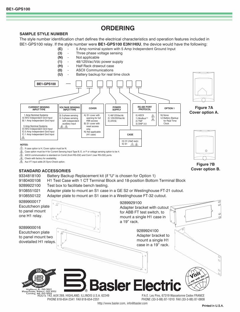
ORDERINGSAMPLE STYLE NUMBERThe style number identification chart defines the electrical characteristics and operation features included inBE1-GPS100 relay. If the style number were BE1-GPS100 E3N1H0U, the device would have the following:
(E) - 5 Amp nominal system with 5 Amp Independent Ground Input(3) - Three phase voltage sensing(N) - Not applicable(1) - 48/125Vac/Vdc power supply(H) - Half Rack drawout case(0) - ASCII Communications(U) - Battery backup for real time clock
Printed in U.S.A.Printed in U.S.A.Printed in U.S.A.Printed in U.S.A.Printed in U.S.A.
ROUTE 143, BOX 269, HIGHLAND, ILLINOIS U.S.A. 62249PHONE 618-654-2341 FAX 618-654-2351
P.A.E. Les Pins, 67319 Wasselonne Cedex FRANCEPHONE (33-3-88) 87-1010 FAX (33-3-88) 87-0808
http://www.basler.com, [email protected]
9289900017Escutcheon plateto panel mountone H1 relay.
9289900016Escutcheon plateto panel mount twodovetailed H1 relays.
9289924100Adapter bracket tomount a single H1case in a 19� rack.
9289929100Adapter bracket with cutoutfor ABB FT test switch, tomount a single H1 case ina 19� rack.
STANDARD ACCESSORIES9334818100 Battery Backup Replacement kit (if "U" is chosen for Option 1)9180400108 H1 Test Case with 1 CT Terminal Block and 18-position Bottom Terminal Block9289922100 Test box to facilitate bench testing.9108551021 Adapter plate to mount an S1 case in a GE S2 or Westinghouse FT-21 cutout.9108550122 Adapter plate to mount an S1 case in a Westinghouse FT-32 cutout.
Figure 7ACover option A.
Figure 7BCover option B.
BE1-GPS100
COVERCURRENT SENSINGINPUT TYPE
POWERSUPPLY
A) W/O Independent Gnd InputB) 1 Amp Independent Gnd Input
D) W/O Independent Gnd InputE) 5 Amp Independent Gnd InputF) 1 Amp Independent Gnd Input
1 Amp Nominal Systems
5 Amp Nominal Systems
1) 48/125Vac/dc2) 125/250Vac/dc3) 24Vdc
A) S1 cover withopening for fullHMI access
B) S1 cover withreset accessonly
N) Not applicable(H1 case) CASE
H) H1 (Half rack)S) S1
RS-485 PORTPROTOCOL
0) ASCII1) Modbus2) TNP3) DNP 3.0
VOLTAGE SENSINGINPUT TYPE
3) 3-phase sensing4) 3-phase sensing
with independentauxiliary input
ASCII communication is standard on Com0 (front RS-232) and Com1 (rear RS-232) ports.Check with factory for availability.Aux VT input adds 25 Sync-Check option.
Case option must be H for Current Sensing Input Type B, E, or F or voltage sensing option to be 4.If case option is H, Cover option must be N.
NOTES:
3
1
4
5
2
OPTION 1
N) NoneU) Battery Backup
for Real TimeClock
1 2
3
4
5 2
2