Embed Size (px)
Citation preview

Beacon 800 Gas MonitorOperator’s Manual
Part Number: 71-0037RK
Revision: F
Released: 4/18/17
www.rkiinstruments.com

Product Warranty
RKI Instruments, Inc. warrants gas alarm equipment sold by us to be free from defects in materials, workmanship, and performance for a period of one year from date of shipment from RKI Instruments, Inc. Any parts found defective within that period will be repaired or replaced, at our option, free of charge. This warranty does not apply to those items, which by their nature, are subject to deterioration or consumption in normal service, and which must be cleaned, repaired, or replaced on a routine basis. Examples of such items are as follows:
Warranty is voided by abuse including mechanical damage, alteration, rough handling, or repair procedures not in accordance with the operator’s manual. This warranty indicates the full extent of our liability, and we are not responsible for removal or replacement costs, local repair costs, transportation costs, or contingent expenses incurred without our prior approval.
THIS WARRANTY IS EXPRESSLY IN LIEU OF ANY AND ALL OTHER WARRANTIES AND REPRESENTATIONS, EXPRESSED OR IMPLIED, AND ALL OTHER OBLIGATIONS OR LIABILITIES ON THE PART OF RKI INSTRUMENTS, INC., INCLUDING BUT NOT LIMITED TO, THE WARRANTY OF MERCHANTABILITY OR FITNESS FOR A PARTICULAR PURPOSE. IN NO EVENT SHALL RKI INSTRUMENTS, INC. BE LIABLE FOR INDIRECT, INCIDENTAL, OR CONSEQUENTIAL LOSS OR DAMAGE OF ANY KIND CONNECTED WITH THE USE OF ITS PRODUCTS OR FAILURE OF ITS PRODUCTS TO FUNCTION OR OPERATE PROPERLY.
This warranty covers instruments and parts sold to users by authorized distributors, dealers, and representatives as appointed by RKI Instruments, Inc.
We do not assume indemnification for any accident or damage caused by the operation of this gas monitor, and our warranty is limited to the replacement of parts or our complete goods.
a) Absorbent cartridges d) Batteries
b) Pump diaphragms and valves e) Filter elements
c) Fuses
Beacon 800 Gas Monitor Operator’s Manual
Table of Contents
Chapter 1: Introduction . . . . . . . . . . . . . . . . . . . . . . . . . . . . . . . . . . . . . . . . . . . . . . . . . . . . . . . 1Overview . . . . . . . . . . . . . . . . . . . . . . . . . . . . . . . . . . . . . . . . . . . . . . . . . . . . . . . . . . . . . . . . . . . . . . . . . . . . 1About the Beacon 800 Gas Monitor . . . . . . . . . . . . . . . . . . . . . . . . . . . . . . . . . . . . . . . . . . . . . . . . . . . . . . 1About This Manual. . . . . . . . . . . . . . . . . . . . . . . . . . . . . . . . . . . . . . . . . . . . . . . . . . . . . . . . . . . . . . . . . . . . 1Specifications . . . . . . . . . . . . . . . . . . . . . . . . . . . . . . . . . . . . . . . . . . . . . . . . . . . . . . . . . . . . . . . . . . . . . . . . . 2
Chapter 2: Description . . . . . . . . . . . . . . . . . . . . . . . . . . . . . . . . . . . . . . . . . . . . . . . . . . . . . . . . 3Overview . . . . . . . . . . . . . . . . . . . . . . . . . . . . . . . . . . . . . . . . . . . . . . . . . . . . . . . . . . . . . . . . . . . . . . . . . . . . 3External Description. . . . . . . . . . . . . . . . . . . . . . . . . . . . . . . . . . . . . . . . . . . . . . . . . . . . . . . . . . . . . . . . . . . 3Internal Description . . . . . . . . . . . . . . . . . . . . . . . . . . . . . . . . . . . . . . . . . . . . . . . . . . . . . . . . . . . . . . . . . . . 4
Chapter 3: Installation & Startup. . . . . . . . . . . . . . . . . . . . . . . . . . . . . . . . . . . . . . . . . . . . . . . 9Overview . . . . . . . . . . . . . . . . . . . . . . . . . . . . . . . . . . . . . . . . . . . . . . . . . . . . . . . . . . . . . . . . . . . . . . . . . . . . 9Mounting the Beacon 800 Gas Monitor . . . . . . . . . . . . . . . . . . . . . . . . . . . . . . . . . . . . . . . . . . . . . . . . . . . 9Wiring the Beacon 800 Gas Monitor . . . . . . . . . . . . . . . . . . . . . . . . . . . . . . . . . . . . . . . . . . . . . . . . . . . . 12Starting Up the Beacon 800 Gas Monitor . . . . . . . . . . . . . . . . . . . . . . . . . . . . . . . . . . . . . . . . . . . . . . . . 18
Chapter 4: Operation . . . . . . . . . . . . . . . . . . . . . . . . . . . . . . . . . . . . . . . . . . . . . . . . . . . . . . . . 19Overview . . . . . . . . . . . . . . . . . . . . . . . . . . . . . . . . . . . . . . . . . . . . . . . . . . . . . . . . . . . . . . . . . . . . . . . . . . . 19Normal Operation . . . . . . . . . . . . . . . . . . . . . . . . . . . . . . . . . . . . . . . . . . . . . . . . . . . . . . . . . . . . . . . . . . . 19Alarm Indications . . . . . . . . . . . . . . . . . . . . . . . . . . . . . . . . . . . . . . . . . . . . . . . . . . . . . . . . . . . . . . . . . . . . 20Viewing & Resetting Min/Max Readings. . . . . . . . . . . . . . . . . . . . . . . . . . . . . . . . . . . . . . . . . . . . . . . . 24
Chapter 5: Configuration Menu. . . . . . . . . . . . . . . . . . . . . . . . . . . . . . . . . . . . . . . . . . . . . . . 25Overview . . . . . . . . . . . . . . . . . . . . . . . . . . . . . . . . . . . . . . . . . . . . . . . . . . . . . . . . . . . . . . . . . . . . . . . . . . . 25Enabling or Disabling Channels . . . . . . . . . . . . . . . . . . . . . . . . . . . . . . . . . . . . . . . . . . . . . . . . . . . . . . . . 26Calibration Mode . . . . . . . . . . . . . . . . . . . . . . . . . . . . . . . . . . . . . . . . . . . . . . . . . . . . . . . . . . . . . . . . . . . . 27Configure Channel Settings Menu. . . . . . . . . . . . . . . . . . . . . . . . . . . . . . . . . . . . . . . . . . . . . . . . . . . . . . 28
Chapter 6: Maintenance . . . . . . . . . . . . . . . . . . . . . . . . . . . . . . . . . . . . . . . . . . . . . . . . . . . . . . 31Overview . . . . . . . . . . . . . . . . . . . . . . . . . . . . . . . . . . . . . . . . . . . . . . . . . . . . . . . . . . . . . . . . . . . . . . . . . . . 31Preventive Maintenance . . . . . . . . . . . . . . . . . . . . . . . . . . . . . . . . . . . . . . . . . . . . . . . . . . . . . . . . . . . . . . 31Troubleshooting . . . . . . . . . . . . . . . . . . . . . . . . . . . . . . . . . . . . . . . . . . . . . . . . . . . . . . . . . . . . . . . . . . . . . 31Replacing the Fuses . . . . . . . . . . . . . . . . . . . . . . . . . . . . . . . . . . . . . . . . . . . . . . . . . . . . . . . . . . . . . . . . . . 33
Chapter 7: Optional Recorder Output Board & Heavy Duty Relay Board . . . . . . . . . . 34Overview . . . . . . . . . . . . . . . . . . . . . . . . . . . . . . . . . . . . . . . . . . . . . . . . . . . . . . . . . . . . . . . . . . . . . . . . . . . 34Recorder Output Board . . . . . . . . . . . . . . . . . . . . . . . . . . . . . . . . . . . . . . . . . . . . . . . . . . . . . . . . . . . . . . . 35Heavy Duty Relay Board. . . . . . . . . . . . . . . . . . . . . . . . . . . . . . . . . . . . . . . . . . . . . . . . . . . . . . . . . . . . . . 38
Parts List . . . . . . . . . . . . . . . . . . . . . . . . . . . . . . . . . . . . . . . . . . . . . . . . . . . . . . . . . . . . . . . . . . . 43
Beacon 800 Gas Monitor Operator’s Manual

Chapter 1: Introduction
OverviewThis chapter briefly describes the Beacon 800 Gas Monitor. This chapter also describes the Beacon 800 Gas Monitor Operator’s Manual (this document). Table 1 at the end of this chapter lists the specifications for the Beacon 800.
About the Beacon 800 Gas MonitorThe Beacon 800 is a fixed-mounted, continuous-monitoring instrument. This multiple channel gas monitor is capable of detecting gas at up to eight locations. The display screens simultaneously display the gas readings of all active channels.
The Beacon 800 includes audible and visual alarms that warn you of hazardous gas conditions. The alarm circuit includes two levels of gas alarms. The fail circuit alerts you to failures in the gas transmitter(s) or Beacon 800.
The Configuration menu allows you to change channel and calibration settings.
About this ManualThe Beacon 800 Gas Monitor Operator’s Manual is organized as follows:
• Chapter 1 is an introduction to the Beacon 800.
• Chapter 2 describes the components of the Beacon 800.
• Chapter 3 describes the installation and start-up procedures of the Beacon 800.
• Chapter 4 describes the operation of the Beacon 800.
• Chapter 5 describes the configuration procedures of the Beacon 800.
• Chapter 6 describes the maintenance of the Beacon 800.
• Chapter 7 describes the optional Recorder Output and Heavy Duty Relay boards.
The Beacon 800 Gas Monitor Operator’s Manual uses the following conventions for notes, cautions, and warnings:
NOTE: Describes additional or critical information.
CAUTION: Describes potential damage to equipment.
WARNING: Describes potential danger that can result in injury or death.
1 • Overview Beacon 800 Gas Monitor Operator’s Manual
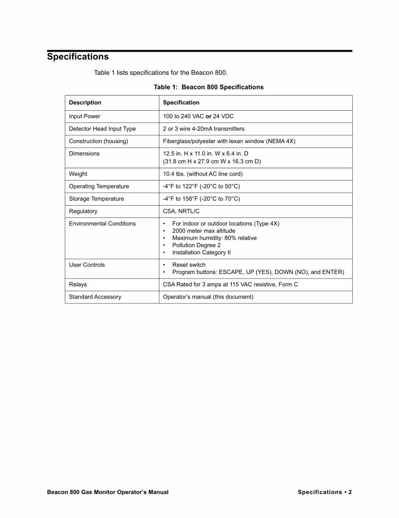
SpecificationsTable 1 lists specifications for the Beacon 800.
Table 1: Beacon 800 Specifications
Description Specification
Input Power 100 to 240 VAC or 24 VDC
Detector Head Input Type 2 or 3 wire 4-20mA transmitters
Construction (housing) Fiberglass/polyester with lexan window (NEMA 4X)
Dimensions 12.5 in. H x 11.0 in. W x 6.4 in. D(31.8 cm H x 27.9 cm W x 16.3 cm D)
Weight 10.4 lbs. (without AC line cord)
Operating Temperature -4°F to 122°F (-20°C to 50°C)
Storage Temperature -4°F to 158°F (-20°C to 70°C)
Regulatory CSA, NRTL/C
Environmental Conditions • For indoor or outdoor locations (Type 4X)• 2000 meter max altitude• Maximum humidity: 80% relative• Pollution Degree 2• Installation Category II
User Controls • Reset switch• Program buttons: ESCAPE, UP (YES), DOWN (NO), and ENTER)
Relays CSA Rated for 3 amps at 115 VAC resistive, Form C
Standard Accessory Operator’s manual (this document)
Beacon 800 Gas Monitor Operator’s Manual Specifications • 2
Chapter 2: Description
OverviewThis chapter describes external and internal components of the Beacon 800 Gas Monitor.
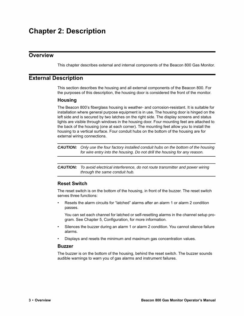
External DescriptionThis section describes the housing and all external components of the Beacon 800. For the purposes of this description, the housing door is considered the front of the monitor.
HousingThe Beacon 800’s fiberglass housing is weather- and corrosion-resistant. It is suitable for installation where general purpose equipment is in use. The housing door is hinged on the left side and is secured by two latches on the right side. The display screens and status lights are visible through windows in the housing door. Four mounting feet are attached to the back of the housing (one at each corner). The mounting feet allow you to install the housing to a vertical surface. Four conduit hubs on the bottom of the housing are for external wiring connections.
CAUTION: Only use the four factory installed conduit hubs on the bottom of the housing for wire entry into the housing. Do not drill the housing for any reason.
CAUTION: To avoid electrical interference, do not route transmitter and power wiring through the same conduit hub.
Reset SwitchThe reset switch is on the bottom of the housing, in front of the buzzer. The reset switch serves three functions:
• Resets the alarm circuits for “latched” alarms after an alarm 1 or alarm 2 condition passes.
You can set each channel for latched or self-resetting alarms in the channel setup pro-gram. See Chapter 5, Configuration, for more information.
• Silences the buzzer during an alarm 1 or alarm 2 condition. You cannot silence failure alarms.
• Displays and resets the minimum and maximum gas concentration values.
BuzzerThe buzzer is on the bottom of the housing, behind the reset switch. The buzzer sounds audible warnings to warn you of gas alarms and instrument failures.
3 • Overview Beacon 800 Gas Monitor Operator’s Manual
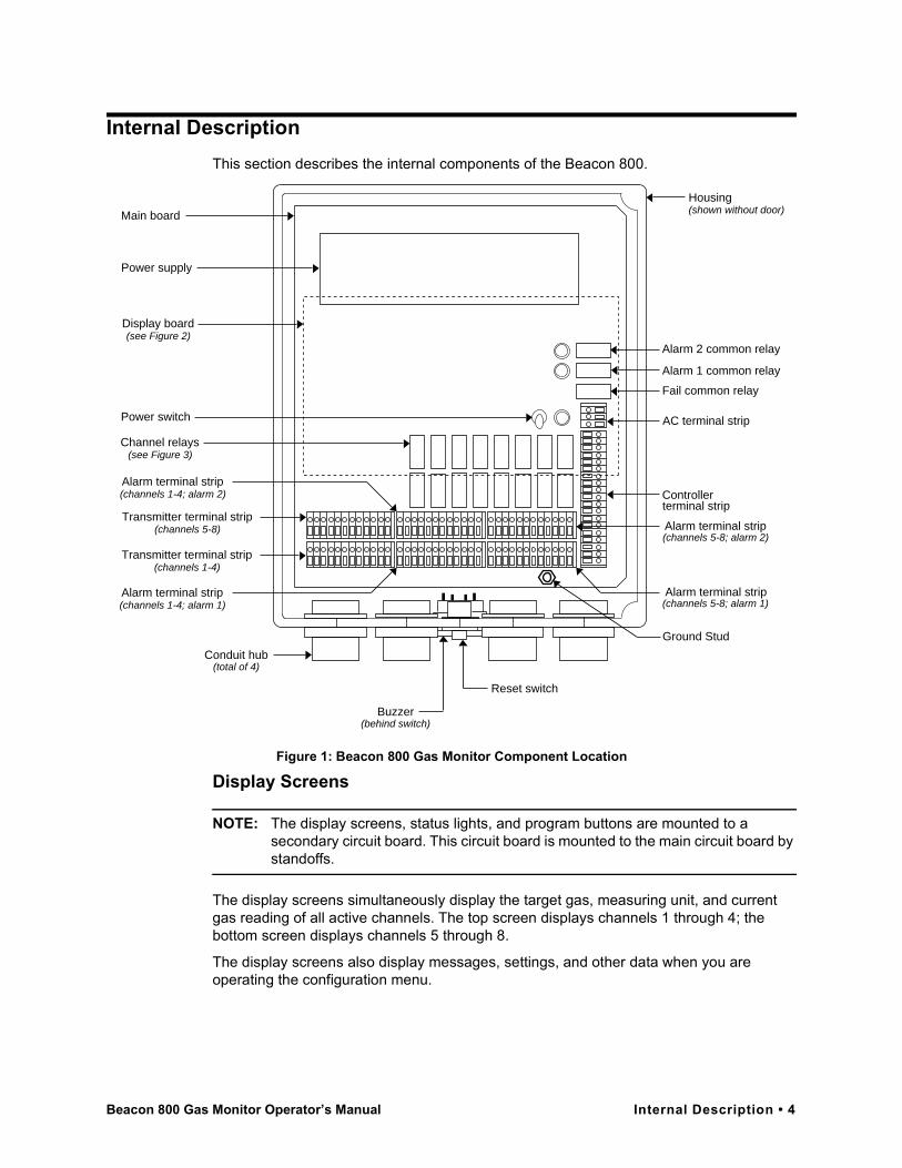
Internal DescriptionThis section describes the internal components of the Beacon 800.
Figure 1: Beacon 800 Gas Monitor Component Location
Display Screens
NOTE: The display screens, status lights, and program buttons are mounted to a secondary circuit board. This circuit board is mounted to the main circuit board by standoffs.
The display screens simultaneously display the target gas, measuring unit, and current gas reading of all active channels. The top screen displays channels 1 through 4; the bottom screen displays channels 5 through 8.
The display screens also display messages, settings, and other data when you are operating the configuration menu.
Housing
AC terminal strip
Controllerterminal strip
Alarm 2 common relay
Alarm 1 common relay
Fail common relay
Conduit hub(total of 4)
Reset switch
Buzzer(behind switch)
Power supply
Display board(see Figure 2)
Power switch
Channel relays(see Figure 3)
Transmitter terminal strip(channels 5-8)
Transmitter terminal strip(channels 1-4)
Alarm terminal strip(channels 5-8; alarm 2)
Alarm terminal strip(channels 5-8; alarm 1)
Alarm terminal strip(channels 1-4; alarm 1)
Alarm terminal strip(channels 1-4; alarm 2)
Main board (shown without door)
Ground Stud
Beacon 800 Gas Monitor Operator’s Manual Internal Description • 4

Figure 2: Display Board Component Location
Status LightsThe Beacon 800 includes four status lights that indicate the current status of the monitor: the ALARM 1 light, the ALARM 2 light, the FAIL light, and the PILOT light (see Figure 2).
PILOT Light
The PILOT light is on when the Beacon 800 is receiving incoming power, either AC or DC power.
FAIL Light
The FAIL light turns on when the Beacon 800 is experiencing a fail condition. A fail condition can be caused by a failure within the Beacon 800 or transmitter(s) wired to the Beacon 800 (see “Chapter 6: Maintenance” on page 31).
ALARM 1 Light
The ALARM 1 light is on when the Beacon 800 is experiencing a low-level (alarm 1) orhigh-level (alarm 2) gas condition.
ALARM 2 Light
The ALARM 2 light is on when the Beacon 800 is experiencing a high-level (alarm 2) gas condition.
Program ButtonsThe Beacon 800 includes four program button that allow you to enter the Configuration Menu, navigate through the menu, update instrument and channel settings, and save changes to the settings. The program buttons, listed in Table 2, are near the right edge of the display board (see Figure 2).
ESCAPE button
UP (YES) button
DOWN (NO) button
ENTER button
PILOT light
ALARM 2 light
ALARM 1 light
Display screen 1(channels 1-4)
Display screen 2(channels 5-8)
FAIL light
Thumbscrew(total of 2)
5 • Internal Description Beacon 800 Gas Monitor Operator’s Manual

Ground StudThe ground stud is used for connecting earth ground to the Beacon 800. The ground stud is factory wired to the GND terminal on the AC terminal strip. The ground stud is located in the lower right corner of the main board.
Terminal StripsThe Beacon 800 includes four terminal strips for external wiring connections. See “Wiring the Beacon 800 Gas Monitor” on page 12 for detailed wiring procedures.
Transmitter Terminal Strips
Two transmitter terminal strips are mounted to the bottom left corner of the main circuit board (see Figure 1). These two 12-point terminal strips facilitate wiring connections to the detector heads. The bottom terminal strip is for channels 1 through 4; the top terminal strip is for channels 5 through 8.
Alarm Terminal Strips
Four alarm terminal strips are to the right of the transmitter terminal strips (see Figure 1). These four 12-point terminal strips facilitate wiring connections to external alarm devices (horn, strobe, etc.). The bottom row of alarm terminals is for alarm 1 connections; the top row of alarm terminals is for alarm 2 connection.
NOTE: The alarm terminal strips provide external alarm connections controlled by individual channels. The Beacon 800 also provides common alarm terminals on the controller terminal strip. The common alarm terminals are controlled by all active channels.
Controller Terminal Strip
The 19-point controller terminal strip is to the right of the alarm terminal strips (see Figure 1). The controller terminal strip facilitates various internal and external wiring connections. Table 3 lists the function of each terminal.
Table 2: Beacon 800 Program Button Functions
Button Function
ESCAPE • Moves backward through the Configuration Menu• Cancels changes you make in the Configuration Menu• Enters the Configuration Menu (press with ENTER button)
UP (YES) • Accepts the displayed setting and proceeds to the next setting• Changes the displayed setting
DOWN (NO) • Allows you to update the displayed setting• Changes the displayed setting
ENTER • Saves changes you make in the Configuration Menu• Enters the Configuration Menu (press with ESCAPE button)
Beacon 800 Gas Monitor Operator’s Manual Internal Description • 6

AC Terminal Strip
The 3-point AC terminal strip is above the controller terminal strip (see Figure 1). The AC terminal strip facilitates wiring connections to the AC power source. The GND terminal is factory wired to the ground stud.
RelaysThe Beacon 800 includes 16 channel relays and three common relays. Both sets of relay contacts are single-pole, double-throw (SPDT) and are rated for 3 amps at 115 VAC (resistive).
NOTE: In the Configuration menu, you can select normally energized, or normally de-energized relays for each channel relay. This section describes the default setting: normally de-energized.
The alarm 1 and alarm 2 common relays are factory-set as normally de-energized and the fail common relay is factory-set as normally energized. The normally energized/normally de-energized setting for the alarm 1, alarm 2, and fail common relays is not user-adjustable.
Channel Relays
The 16-channel relays are above the alarm terminal strips (see Figure 1). These relays are dedicated to specific channels and alarm levels.
Table 3: Terminal Assignments for the Controller Terminal Strip
Terminal No. Connects to:
24VDC(BAT-/BAT+)
DC power source (you can use DC power as a primary or backup power source.)1
ALM2(C, NO, NC)
Common alarm 2 (external alarm)2
ALM1(C, NO, NC)
Common alarm 1 (external alarm)3
FAIL(C, NO, NC)
Common fail (external alarm)4
+28V Not used
TX Not used
RX Not used
GND Not used
RESET (2) Reset switch (factory-wired)
BUZ-/BUZ+ Internal buzzer (factory-wired)
1 If used as primary power source do not make wiring connections to the AC terminal strip.2 Activates if any gas channel recognizes an alarm 2 condition.3 Activates if any gas channel recognizes an alarm 1 condition.4 Activates if any gas channel or the Beacon 800 recognizes a fail condition.
7 • Internal Description Beacon 800 Gas Monitor Operator’s Manual
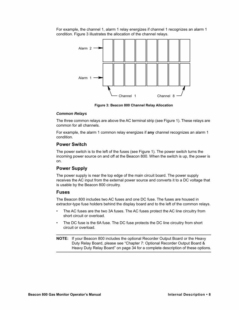
For example, the channel 1, alarm 1 relay energizes if channel 1 recognizes an alarm 1 condition. Figure 3 illustrates the allocation of the channel relays.
Figure 3: Beacon 800 Channel Relay Allocation
Common Relays
The three common relays are above the AC terminal strip (see Figure 1). These relays are common for all channels.
For example, the alarm 1 common relay energizes if any channel recognizes an alarm 1 condition.
Power SwitchThe power switch is to the left of the fuses (see Figure 1). The power switch turns the incoming power source on and off at the Beacon 800. When the switch is up, the power is on.
Power SupplyThe power supply is near the top edge of the main circuit board. The power supply receives the AC input from the external power source and converts it to a DC voltage that is usable by the Beacon 800 circuitry.
FusesThe Beacon 800 includes two AC fuses and one DC fuse. The fuses are housed in extractor-type fuse holders behind the display board and to the left of the common relays.
• The AC fuses are the two 3A fuses. The AC fuses protect the AC line circuitry from short circuit or overload.
• The DC fuse is the 6A fuse. The DC fuse protects the DC line circuitry from short circuit or overload.
NOTE: If your Beacon 800 includes the optional Recorder Output Board or the Heavy Duty Relay Board, please see “Chapter 7: Optional Recorder Output Board & Heavy Duty Relay Board” on page 34 for a complete description of these options.
Channel 8
Alarm 1
Channel 1
Alarm 2
Beacon 800 Gas Monitor Operator’s Manual Internal Description • 8
Chapter 3: Installation and Start Up
OverviewThis chapter describes procedures showing how to mount the Beacon 800 Gas Monitor, to make wiring connections to the monitor, and to start up the monitor.
WARNING: Perform all installation and start-up procedures in a “fresh air” environment of normal oxygen content, and known to be free of combustible and toxic gas. The Beacon 800 is not in operation as a gas monitoring system until the start-up procedure is complete.
Mounting the Beacon 800 Gas MonitorPerform the following procedure to install the Beacon 800 at the mounting site.
1. Select the mounting site. When you select the mounting site, consider the following factors:
• Is an AC or DC power source available?
• Is there enough room to open the housing door and make wiring connections through the conduit hubs at the bottom of the housing?
• Are the display screens and status lights visible?
2. Close and latch the housing door.3. Position the monitor on a vertical surface at eye level (4 1/2 to 5 feet from the floor).
4. The Beacon 800 is shipped with the mounting feet positioned under the housing. Loosen the screws that secure the feet to the housing, rotate the feet to their mounting position (as shown in Figure 4), then tighten the screws.
5. Insert 1/4 in. screws through the slots in the mounting feet at each corner of the housing to secure the housing to the mounting surface (see Figure 4).
9 • Overview Beacon 800 Gas Monitor Operator’s Manual
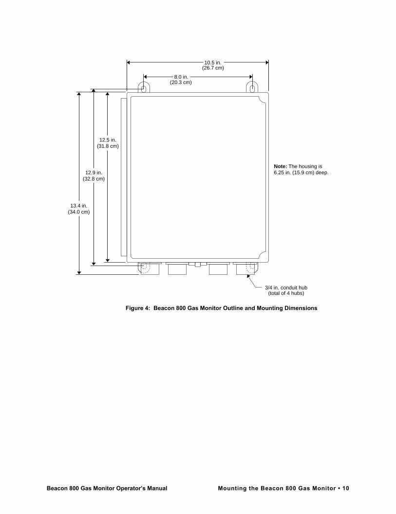
Figure 4: Beacon 800 Gas Monitor Outline and Mounting Dimensions
8.0 in.
Note: The housing is6.25 in. (15.9 cm) deep.
12.5 in.(31.8 cm)
12.9 in.(32.8 cm)
13.4 in.(34.0 cm)
10.5 in.
3/4 in. conduit hub(total of 4 hubs)
(26.7 cm)
(20.3 cm)
Beacon 800 Gas Monitor Operator’s Manual Mounting the Beacon 800 Gas Monitor • 10

Figure 5: Beacon 800 Gas Monitor External Wiring Diagram
100-
240
VA
CN
ote:
Do
not c
onne
ct A
Cpo
wer
if 2
4 V
DC
is t
hepr
imar
ypo
wer
sou
rce.
(fac
tory
wire
d)
+
Ala
rm 1
Ter
min
al S
trip
for
C
hann
els
1 -
4 (t
ypic
al w
iring
)
Not
U
sed
Ala
rm
Dev
ices
2 w
ire 4
- 2
0 m
A
Tra
nsm
itter
Ter
min
als
(t
ypic
al)
Buz
zer
(fac
tory
wire
d)
FB
(4
- 20
mA
)
+ 24
VD
C
-(D
C G
roun
d)
Con
tact
Rat
ing
of 1
0 A
mps
R
esis
tive
at 2
50 V
AC
for
Eac
h S
etof
Ala
rm R
elay
Con
tact
s.
Ala
rm
Dev
ices
Ind
ivid
ualA
larm
Rel
ay W
irin
g
AC
Pow
er W
irin
g Gro
und
Stu
d
Gro
und
Line
(H
ot)
Neu
tral
3 w
ire 4
- 2
0 m
A
Tra
nsm
iter
Ter
min
als
(typ
ical
)
FB
(4
- 20
mA
)
+ 24
VD
C
Tra
nsm
itte
r W
irin
g
Co
mm
onA
larm
Rel
ay W
irin
g(t
ypic
al w
iring
)A
larm
Dev
ice
Pow
er
Ala
rm
Dev
ice
Pow
er
24 V
DC
Bat
tery
Res
et S
witc
h(f
acto
ry w
ired)
11 • Mounting the Beacon 800 Gas Monitor Beacon 800 Gas Monitor Operator’s Manual
Wiring the Beacon 800 Gas MonitorThis section describes procedures to connect the AC power source, DC power source, external alarms, and detector heads. See Figure 5 for a general wiring diagram of all external wiring to the Beacon 800.
NOTE: All connections to building electrical systems must be installed in accordance with local requirements and must be installed by qualified personnel.
WARNING: Make all connections to the Beacon 800 before you plug in or turn on the AC or DC power source. Before you make any wiring adjustments, always verify that all power sources are not live.
Routing Wiring Into the Beacon 800 HousingWiring must be brought into the housing through one of the four factory-installed conduit hubs on the bottom of the housing.
Do not drill into the Beacon 800 housing for any reason. Drilling the Beacon 200 housing and routing wiring through holes not factory drilled will void the warranty and could result in:
• Damage to internal components from the drilling process.
• Moisture damage to internal components from poorly sealed holes.
• Unpredictable Beacon 800 behavior due to EMI/RFI interference caused by wires routed across the PCBs.
• Possible shorting of Beacon 800 components due to wires routed across the PCBs.
Accessing the Terminal StripsPerform the following procedure to gain access to the AC and controller terminal strips, which are located behind the display board.
1. Turn off or unplug all incoming power to the Beacon 800 at the power source end.
2. Open the housing door, then place the power switch in the OFF position.3. Loosen the two captive thumbscrews (on the right side of the display board) that
secure the board to the standoffs, until the screws are disengaged from the standoffs.
4. Gently pull the right side of the display board out toward the housing door. (The standoffs under the left side of the display board are hinged, which allows the display board to move in this manner.)
Beacon 800 Gas Monitor Operator’s Manual Wiring the Beacon 800 Gas Monitor • 12
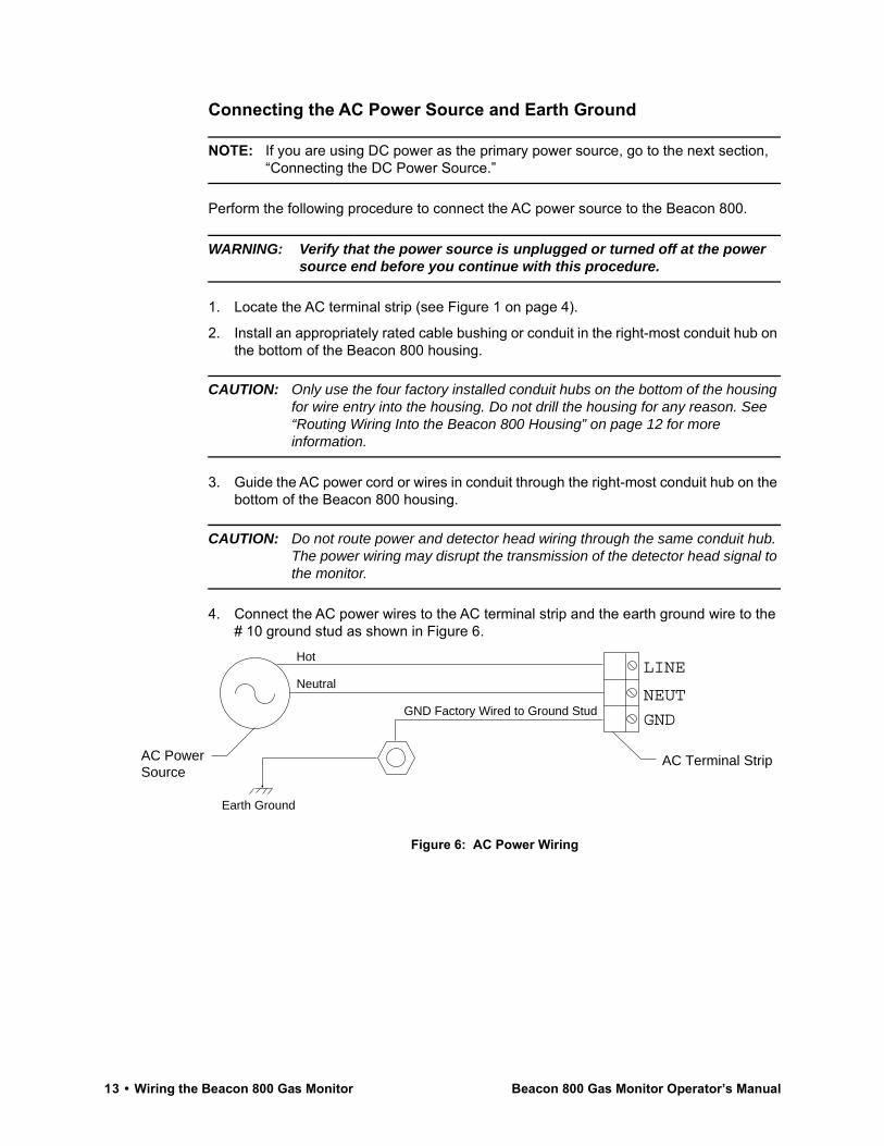
Connecting the AC Power Source and Earth Ground
NOTE: If you are using DC power as the primary power source, go to the next section, “Connecting the DC Power Source.”
Perform the following procedure to connect the AC power source to the Beacon 800.
WARNING: Verify that the power source is unplugged or turned off at the power source end before you continue with this procedure.
1. Locate the AC terminal strip (see Figure 1 on page 4).
2. Install an appropriately rated cable bushing or conduit in the right-most conduit hub on the bottom of the Beacon 800 housing.
CAUTION: Only use the four factory installed conduit hubs on the bottom of the housing for wire entry into the housing. Do not drill the housing for any reason. See “Routing Wiring Into the Beacon 800 Housing” on page 12 for more information.
3. Guide the AC power cord or wires in conduit through the right-most conduit hub on the bottom of the Beacon 800 housing.
CAUTION: Do not route power and detector head wiring through the same conduit hub. The power wiring may disrupt the transmission of the detector head signal to the monitor.
4. Connect the AC power wires to the AC terminal strip and the earth ground wire to the # 10 ground stud as shown in Figure 6.
Figure 6: AC Power Wiring
NEUT
GND
AC Terminal StripAC PowerSource
LINEHot
Neutral
GND Factory Wired to Ground Stud
Earth Ground
13 • Wiring the Beacon 800 Gas Monitor Beacon 800 Gas Monitor Operator’s Manual
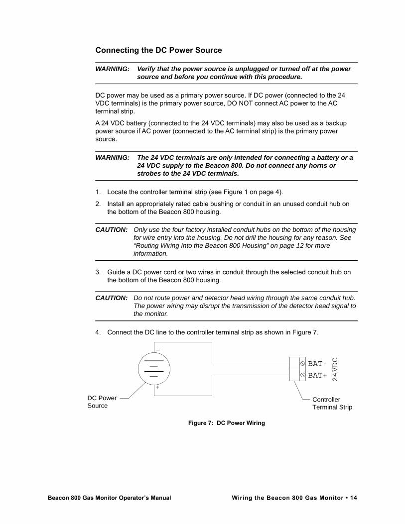
Connecting the DC Power Source
WARNING: Verify that the power source is unplugged or turned off at the power source end before you continue with this procedure.
DC power may be used as a primary power source. If DC power (connected to the 24 VDC terminals) is the primary power source, DO NOT connect AC power to the AC terminal strip.
A 24 VDC battery (connected to the 24 VDC terminals) may also be used as a backup power source if AC power (connected to the AC terminal strip) is the primary power source.
WARNING: The 24 VDC terminals are only intended for connecting a battery or a 24 VDC supply to the Beacon 800. Do not connect any horns or strobes to the 24 VDC terminals.
1. Locate the controller terminal strip (see Figure 1 on page 4).
2. Install an appropriately rated cable bushing or conduit in an unused conduit hub on the bottom of the Beacon 800 housing.
CAUTION: Only use the four factory installed conduit hubs on the bottom of the housing for wire entry into the housing. Do not drill the housing for any reason. See “Routing Wiring Into the Beacon 800 Housing” on page 12 for more information.
3. Guide a DC power cord or two wires in conduit through the selected conduit hub on the bottom of the Beacon 800 housing.
CAUTION: Do not route power and detector head wiring through the same conduit hub. The power wiring may disrupt the transmission of the detector head signal to the monitor.
4. Connect the DC line to the controller terminal strip as shown in Figure 7.
Figure 7: DC Power Wiring
BAT-
BAT+
DC PowerSource
ControllerTerminal Strip
+
24VDC
Beacon 800 Gas Monitor Operator’s Manual Wiring the Beacon 800 Gas Monitor • 14
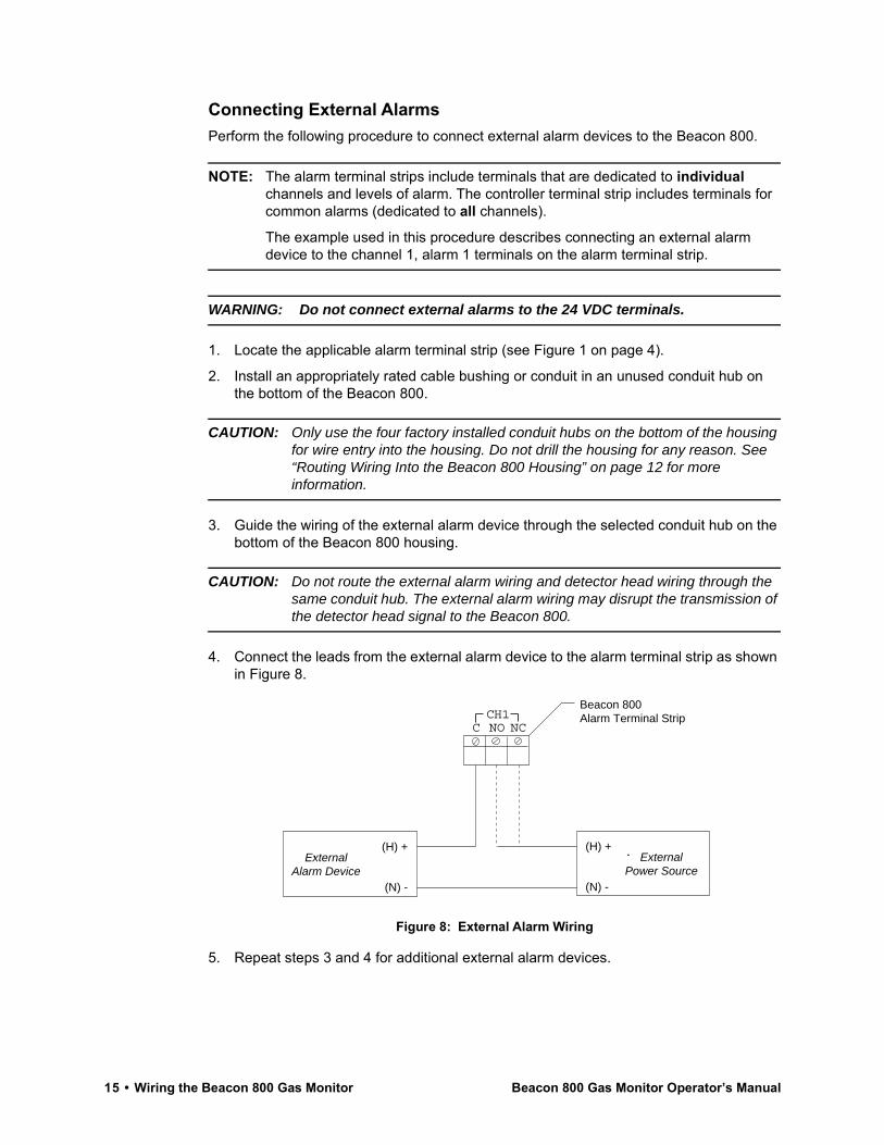
Connecting External AlarmsPerform the following procedure to connect external alarm devices to the Beacon 800.
NOTE: The alarm terminal strips include terminals that are dedicated to individual channels and levels of alarm. The controller terminal strip includes terminals for common alarms (dedicated to all channels).
The example used in this procedure describes connecting an external alarm device to the channel 1, alarm 1 terminals on the alarm terminal strip.
WARNING: Do not connect external alarms to the 24 VDC terminals.
1. Locate the applicable alarm terminal strip (see Figure 1 on page 4).
2. Install an appropriately rated cable bushing or conduit in an unused conduit hub on the bottom of the Beacon 800.
CAUTION: Only use the four factory installed conduit hubs on the bottom of the housing for wire entry into the housing. Do not drill the housing for any reason. See “Routing Wiring Into the Beacon 800 Housing” on page 12 for more information.
3. Guide the wiring of the external alarm device through the selected conduit hub on the bottom of the Beacon 800 housing.
CAUTION: Do not route the external alarm wiring and detector head wiring through the same conduit hub. The external alarm wiring may disrupt the transmission of the detector head signal to the Beacon 800.
4. Connect the leads from the external alarm device to the alarm terminal strip as shown in Figure 8.
Figure 8: External Alarm Wiring
5. Repeat steps 3 and 4 for additional external alarm devices.
Beacon 800Alarm Terminal Strip
ExternalAlarm Device
(H) +
(N) -
C NO NCCH1
ExternalPower Source
(H) +
(N) -
15 • Wiring the Beacon 800 Gas Monitor Beacon 800 Gas Monitor Operator’s Manual
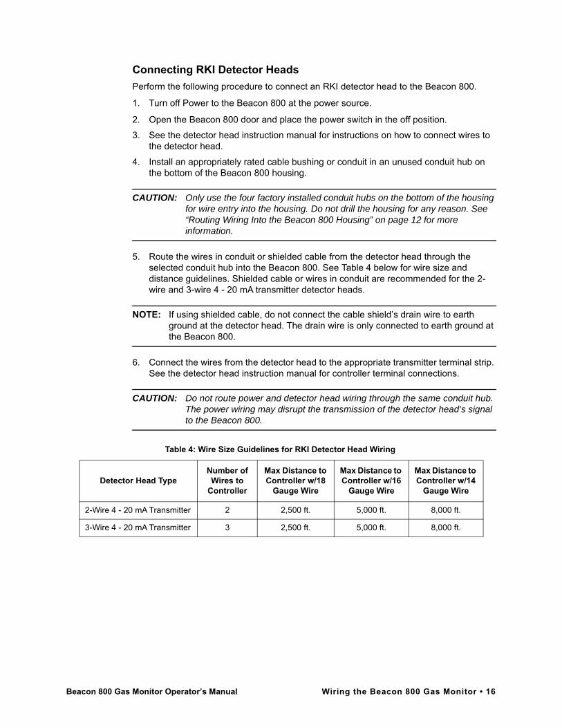
Connecting RKI Detector HeadsPerform the following procedure to connect an RKI detector head to the Beacon 800.
1. Turn off Power to the Beacon 800 at the power source.
2. Open the Beacon 800 door and place the power switch in the off position.3. See the detector head instruction manual for instructions on how to connect wires to
the detector head.
4. Install an appropriately rated cable bushing or conduit in an unused conduit hub on the bottom of the Beacon 800 housing.
CAUTION: Only use the four factory installed conduit hubs on the bottom of the housing for wire entry into the housing. Do not drill the housing for any reason. See “Routing Wiring Into the Beacon 800 Housing” on page 12 for more information.
5. Route the wires in conduit or shielded cable from the detector head through the selected conduit hub into the Beacon 800. See Table 4 below for wire size and distance guidelines. Shielded cable or wires in conduit are recommended for the 2-wire and 3-wire 4 - 20 mA transmitter detector heads.
NOTE: If using shielded cable, do not connect the cable shield’s drain wire to earth ground at the detector head. The drain wire is only connected to earth ground at the Beacon 800.
6. Connect the wires from the detector head to the appropriate transmitter terminal strip. See the detector head instruction manual for controller terminal connections.
CAUTION: Do not route power and detector head wiring through the same conduit hub. The power wiring may disrupt the transmission of the detector head’s signal to the Beacon 800.
Table 4: Wire Size Guidelines for RKI Detector Head Wiring
Detector Head TypeNumber of Wires to
Controller
Max Distance to Controller w/18
Gauge Wire
Max Distance to Controller w/16
Gauge Wire
Max Distance to Controller w/14
Gauge Wire
2-Wire 4 - 20 mA Transmitter 2 2,500 ft. 5,000 ft. 8,000 ft.
3-Wire 4 - 20 mA Transmitter 3 2,500 ft. 5,000 ft. 8,000 ft.
Beacon 800 Gas Monitor Operator’s Manual Wiring the Beacon 800 Gas Monitor • 16

Connecting User-Supplied 4 - 20 mA TransmittersThe Beacon 800 may be used with a user supplied 2-wire or 3-wire 4 - 20 mA transmitter which runs on 24 VDC nominal (the Beacon 800 supplies 28VDC). When this is done, the Beacon 800 is normally setup at RKI Instruments with the following channel parameters: unit of measure, item name, and full scale. For example, “PSI AIR” with a full scale of 10 PSI.
Perform the following procedure to connect a 4 - 20 mA transmitter, which you supply, to the Beacon 800.
1. Turn off power to the Beacon 800 at the power source.
2. Open the Beacon 800 door and turn off the power switch.3. See the transmitter’s instruction manual for instructions on how to connect wires to the
transmitter.
4. Install an appropriately rated cable bushing or conduit in an unused conduit hub on the bottom of the Beacon 800 housing.
CAUTION: Only use the four factory installed conduit hubs on the bottom of the housing for wire entry into the housing. Do not drill the housing for any reason. See “Routing Wiring Into the Beacon 800 Housing” on page 12 for more information.
5. Route the wires from the transmitter through the selected conduit hub into the Beacon 800.
6. Connect the wires from the transmitter to the appropriate transmitter terminal strip. See the transmitter instruction manual for controller terminal connections.
CAUTION: Do not route power and transmitter wiring through the same conduit hub. The power wiring may disrupt the transmission of the transmitter’s signal to the Beacon 800.
Figure 9 below illustrates typical transmitter wiring connections.
NOTE: If your Beacon 800 includes the recorder output board or heavy duty relay board, see “Chapter 7: Optional Recorder Output Board & Heavy Duty Relay Board” on page 34 for wiring instructions.
Beacon 800Transmitter Terminal Strip
-FB
Transmitter
3-Wire Connection
+
+ S -CH1
(24 VDC)
(4 - 20 mA)
(DC Ground)
Beacon 800Transmitter Terminal Strip
2-Wire Connection
+ S -CH1
FB
Transmitter
+ (24 VDC)
(4 - 20 mA)
Figure 9: Generic 4 to 20 mA Transmitter Output Wiring
17 • Wiring the Beacon 800 Gas Monitor Beacon 800 Gas Monitor Operator’s Manual

Starting Up the Beacon 800 Gas MonitorPerform the following procedure to place the Beacon 800 into normal operation.
1. Complete the mounting and wiring procedures described earlier in this chapter.
2. Complete all installation procedures described in the detector head or user supplied 4 - 20 mA transmitter instruction manual.
3. Verify that all wiring connections are correct and secure and that the Beacon 800’s power switch is in the OFF position.
4. Plug in or turn on the incoming power source (AC or DC) at the power source end.5. Place the Beacon 800’s power switch in the ON position. RKI INSTRUMENTS
appears on the top display and BEACON 800 appears on the bottom display for a few seconds, then WARMING UP appears for each active channel. The warm-up period will last for one minute.
NOTE: To prevent unwanted alarms during warm up, the alarm circuits are not active while the WARMING UP message is displayed.
6. Verify that the PILOT light is on. If the PILOT light is not on, see the troubleshooting guide in Chapter 6, Maintenance.
7. Perform the start-up procedure for each detector head or user supplied 4 - 20 mA transmitter as described in the detector head or transmitter instruction manual.
NOTE: If your Beacon 800 includes the optional Recorder Output Board or the Heavy Duty Relay Board, please see “Chapter 7: Optional Recorder Output Board & Heavy Duty Relay Board” on page 34 for a complete description of these components.
Beacon 800 Gas Monitor Operator’s Manual Starting Up the Beacon 800 Gas Monitor • 18

Chapter 4: Operation
OverviewThis chapter describes the Beacon 800 Gas Monitor in normal operation. This chapter also describes the Beacon 800 in alarm 1, alarm 2, and fail conditions, and suggests responses to these conditions.
Normal OperationNormal operation is defined as follows:
• the start-up procedure is complete.
• the Beacon 800 is not indicating an alarm 1, alarm 2, or fail condition.
• the Beacon 800 is not running the Configuration menu.
During normal operation, the Beacon 800 simultaneously displays the target gas, unit of measure, and current gas reading for all active channels. The top screen displays channels 1 through 4; the bottom screen displays channels 5 through 8.
Figure 10: Target Gas Display
The PILOT light is on indicating that the Beacon 800 is receiving incoming power.
1234
0
00
2 0 . 9% L E
P P M
P P M
%C H 4
O X YC OH 2 S
L::::
5678
0
00
2 0 . 9% L E
P P M
P P M
%C H 4
O X YC OH 2 S
L::::
19 • Overview Beacon 800 Gas Monitor Operator’s Manual
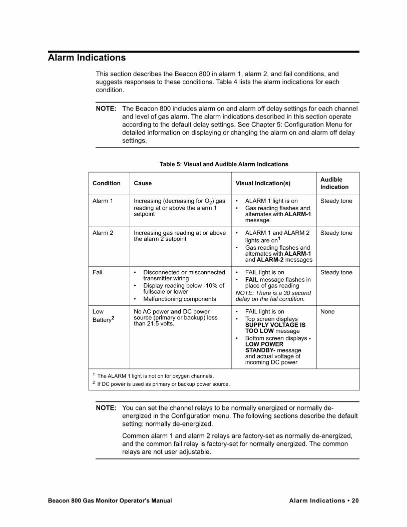
Alarm IndicationsThis section describes the Beacon 800 in alarm 1, alarm 2, and fail conditions, and suggests responses to these conditions. Table 4 lists the alarm indications for each condition.
NOTE: The Beacon 800 includes alarm on and alarm off delay settings for each channel and level of gas alarm. The alarm indications described in this section operate according to the default delay settings. See Chapter 5: Configuration Menu for detailed information on displaying or changing the alarm on and alarm off delay settings.
NOTE: You can set the channel relays to be normally energized or normally de-energized in the Configuration menu. The following sections describe the default setting: normally de-energized.
Common alarm 1 and alarm 2 relays are factory-set as normally de-energized, and the common fail relay is factory-set for normally energized. The common relays are not user adjustable.
Table 5: Visual and Audible Alarm Indications
Condition Cause Visual Indication(s) Audible Indication
Alarm 1 Increasing (decreasing for O2) gas reading at or above the alarm 1 setpoint
• ALARM 1 light is on• Gas reading flashes and
alternates with ALARM-1 message
Steady tone
Alarm 2 Increasing gas reading at or above the alarm 2 setpoint
• ALARM 1 and ALARM 2 lights are on1
• Gas reading flashes and alternates with ALARM-1 and ALARM-2 messages
Steady tone
Fail • Disconnected or misconnected transmitter wiring
• Display reading below -10% of fullscale or lower
• Malfunctioning components
• FAIL light is on• FAIL message flashes in
place of gas readingNOTE: There is a 30 second delay on the fail condition.
Steady tone
Low Battery2
No AC power and DC power source (primary or backup) less than 21.5 volts.
• FAIL light is on• Top screen displays
SUPPLY VOLTAGE IS TOO LOW message
• Bottom screen displays -LOW POWER STANDBY- message and actual voltage of incoming DC power
None
1 The ALARM 1 light is not on for oxygen channels.2 If DC power is used as primary or backup power source.
Beacon 800 Gas Monitor Operator’s Manual Alarm Indications • 20
Alarm 1 ConditionThis section describes the audible and visual indications for an alarm 1 condition and suggests responses to an alarm 1 condition.
Alarm 1 Condition Indications
When the gas reading of an active channel reaches the alarm 1 setpoint, the Beacon 800 senses an alarm 1 condition. The Beacon 800 alerts you to an alarm 1 condition as follows:
• the ALARM 1 light turns on;• the gas reading in alarm 1 condition flashes and alternates with the ALARM-1
message;• the buzzer sounds a steady tone;• the common alarm 1 relay energizes;• the applicable alarm 1 channel relay energizes.Responding to an Alarm 1 Condition
This section suggests the following responses to an alarm 1 condition:
1. Follow your established procedure for a low-level combustible or toxic gas condition or a decreasing oxygen condition.
2. Oxygen alarms are factory set as self-resetting and will automatically clear when the oxygen reading rises above the alarm 1 setpoint.
3. Alarms for all other gas types are factory set as latching. After the gas reading falls below (rises above for oxygen) the alarm 1 setpoint, press the reset switch to reset the alarm 1 circuit. Resetting the alarm 1 circuit silences the buzzer, turns off the ALARM 1 light, resets the channel display, and de-energizes the common and channel alarm 1 relays.
NOTE: To silence the buzzer while in an alarm 1 condition, press the reset switch.You cannot de-energize the alarm 1 relays until the gas reading falls below (rises above for oxygen) the alarm 1 setpoint.
Alarm 2 ConditionThis section describes the audible and visual indications for an alarm 2 condition and suggests responses to an alarm 2 condition.
Alarm 2 Condition Indications
When the gas reading of an active channel reaches the alarm 2 setpoint, the Beacon 800 senses an alarm 2 condition. The Beacon 800 alerts you to an alarm 2 condition as follows:
• the ALARM 2 light turns on;
• the gas reading during an alarm 2 condition continues to flash and alternates with the ALARM-1 and ALARM-2 messages;
• the buzzer sounds a steady tone;• the common alarm 2 relay energizes;• the applicable alarm 2 channel relay energizes.
21 • Alarm Indications Beacon 800 Gas Monitor Operator’s Manual

Responding to an Alarm 2 Condition
This section suggests responses to an alarm 2 condition.
1. Follow your established procedure for a high-level combustible or toxic gas condition, or an increasing oxygen condition.
2. Oxygen alarms are factory set as self-resetting and will automatically clear when the oxygen reading rises above the alarm 2 setpoint.
3. Alarms for all other gas types are factory set as latching. After the gas reading falls below the alarm 2 setpoint, press the reset switch to reset the alarm circuit. Resetting the alarm circuit turns off the ALARM 2 light, and de-energizes the common and channel alarm 2 relays.
NOTE: To silence the buzzer while in an alarm 2 condition, press the reset switch.You cannot de-energize the alarm 2 relays until the gas reading falls below the alarm 2 setpoint.
Fail ConditionThis section describes the audible and visual indications for a fail condition and suggests responses to a fail condition.
Fail Condition Indications
The Beacon 800 senses a fail condition for any of the following:
• the transmitter wiring is disconnected or incorrectly connected;
• the display reading is -10% of full scale or lower;
• the Beacon 800 or transmitter is malfunctioning.
When the Beacon 800 senses a fail condition, it alerts you as follows:
• the FAIL light turns on;
• the gas reading for the failing channel is replaced by the FAIL message;
• the buzzer sounds a steady tone;
• the common fail relay de-energizes.
NOTE: The fail alarm has a 30 second delay.
NOTE: If you elected to use the channel’s alarm 2 relay as an individual fail relay in the Configuration menu, the relay de-energizes in a fail condition. See Chapter 5: Configuration Menu.
Responding to a Fail Condition
This section suggests responses to a fail condition.
1. Verify that the transmitter wiring is correctly and securely connected.
2. See the troubleshooting guide in Chapter 6, Maintenance.
Beacon 800 Gas Monitor Operator’s Manual Alarm Indications • 22
Low Battery ConditionThis section describes the audible and visual indications for a low battery condition and suggests responses to a low battery condition. This condition only applies when DC power is used as a primary or backup power source.
NOTE: When a 24 VDC battery is used as a backup power source, the Beacon 800 keeps the battery charged by providing a trickle charge from the AC power source. If AC power is interrupted, the Beacon 800 will operate from the DC backup battery until the battery voltage drops to 21.5 volts or less.
Low Battery Condition Indications
The Beacon 800 senses a low battery condition when:
• AC power is disconnected, misconnected, or interrupted
AND
• the DC power source is 21.5 volts or less.
When the Beacon 800 senses a low battery condition, it alerts you as follows:
• the FAIL light turns on;
• the top screen displays the SUPPLY VOLTAGE IS TOO LOW message;
• the bottom screen displays the -LOW POWER STANDBY- message and actual voltage of incoming DC power.
Responding to a Low Battery Condition
This section suggests responses to a low battery condition.
• If DC power is the primary power source:
1. For a temporary DC power source, disconnect primary DC power at the Beacon 800, then connect a 24 VDC backup battery;
2. Determine and correct the cause of primary DC power loss.
When the DC power source rises above 22.0 volts, the Beacon 800 begins the warm up process.
• If DC power is the backup power source:
1. Replace or recharge the 24 VDC backup battery to resume backup power capability;
2. Determine and correct the cause of primary AC power loss.
When backup DC or primary AC power is restored, the Beacon 800 begins the warm up process. When AC power is restored, the Beacon 800 charges the battery until it is fully recharged. Charge time varies depending on the battery size and how much the battery was depleted. Once the battery is fully charged, the Beacon 800 reverts to a trickle charge to maintain the battery charge.
23 • Alarm Indications Beacon 800 Gas Monitor Operator’s Manual

Viewing & Resetting Min/Max ReadingsThe Reset switch may be used to view and reset the minimum and maximum gas readings for all active channels.
1. While the Beacon 100 is in normal operation, press and hold the Reset switch button for 3 seconds.
2. The display will indicate MIN / MAX Display on the top display and the bottom display will indicate Press RESET when done viewing . . . for 5 seconds before displaying the minimum and maximum readings for all active channels. The minimum reading is on the left and the maximum is on the right side of the display for each channel.
3. Press and release the Reset switch button to exit the min/max screen. The top display will indicate To RESET Min/MAX Values and the bottom display will indicate Press and HOLD RESET Button for 10 seconds and then return to normal operation.
• To return to normal operation without resetting the minimum and maximum read-ings, do not press the Reset switch button and allow the unit to return to normal operation.
• To reset the minimum and maximum readings, before the unit returns to normal operation press and hold the Reset switch button until the display indicates Min/Max Values Have Been Reset. Release the Reset switch button. The unit will then return to normal operation.
Beacon 800 Gas Monitor Operator’s Manual Viewing & Resetting Min/Max Readings • 24
Chapter 5: Configuration Menu
OverviewThis section describes how to use the Beacon 800s Configuration menu.With the Configuration menu, you can:
• enable/disable channels
• enter calibration mode to calibrate a detector head• set channel parameters
• program the heavy duty relay relays (optional feature)
NOTE: Channels included with the original shipment of the Beacon 800 are set up at the factory. If you are adding a channel to an existing Beacon 800, the channel must be configured as described in this section before it can be an active monitoring channel.
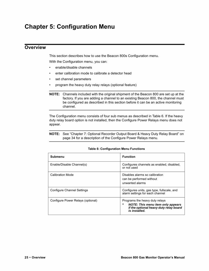
The Configuration menu consists of four sub menus as described in Table 6. If the heavy duty relay board option is not installed, then the Configure Power Relays menu does not appear.
NOTE: See “Chapter 7: Optional Recorder Output Board & Heavy Duty Relay Board” on page 34 for a description of the Configure Power Relays menu.
Table 6: Configuration Menu Functions
Submenu Function
Enable/Disable Channel(s) Configures channels as enabled, disabled, or not used
Calibration Mode Disables alarms so calibration can be performed without unwanted alarms
Configure Channel Settings Configures units, gas type, fullscale, and alarm settings for each channel
Configure Power Relays (optional) Programs the heavy duty relays* NOTE: This menu item only appears
if the optional heavy duty relay board is installed.
25 • Overview Beacon 800 Gas Monitor Operator’s Manual

Enabling or Disabling Channels1. To enter the Configuration menu, simultaneously press and hold the ESCAPE and
ENTER buttons for approximately 5 seconds. Release the buttons when the You Have Entered the Configuration Menu... message appears on the top display screen.
NOTE: The Configuration menu includes a 5-minute time-out feature. If you do not perform an action within 5 minutes of the previous action, the Beacon 800 automatically returns to normal operation.
2. Press the UP (YES) button to continue.3. Press the UP (YES) or DOWN (NO) button until the 1) Enable/Disable Channel(s)
message appears on the bottom display screen, then press the ENTER button.4. Use the UP (YES) and DOWN (NO) buttons to select the channel (or all channels) you
want to enable or disable, then press the ENTER button.5. Press the DOWN (NO) button. The CHANNEL USAGE setting displays on the bottom
display screen.6. Use the UP (YES) and DOWN (NO) buttons to display the setting you want, then
press the ENTER button to select the setting. Table 6 describes the three available settings.
7. Press the ESCAPE button, then press the DOWN/NO button to return to normal operation.
Table 7: Beacon 800 Channel Usage Settings
Setting Description
CHANNEL ENABLED The Beacon 800 displays gas readings and initiates gas and channel failure alarms when appropriate.Use this setting for normal operation when the channel has a transmitter wired to it.
CHANNEL DISABLED The Beacon 800 displays DISABLED for the channel and the channel’s alarm circuit is not active.Use this setting when the channel has a transmitter wired to it, but gas readings and alarms are not required for the channel (for example if the transmitter requires maintenance or is malfunctioning).
CHANNEL NOT USED The Beacon 800 leaves the channel blank on the display screen.Use this setting when the channel does not have a transmitter wired to it.
Beacon 800 Gas Monitor Operator’s Manual Enabling or Disabling Channels • 26
Calibration ModeThis section describes how to use calibration mode to calibrate a detector head.
WARNING: The Beacon 800 is not an active gas monitoring device during the calibration procedure.
Entering Calibration Mode1. Assemble the calibration kit(s). See the instruction manual for each detector head for
procedures specific to that detector head.
2. Open the Beacon 800’s housing door, and locate the program buttons to the right of the display screens.
3. Simultaneously press and hold the ESCAPE and ENTER buttons for approximately5 seconds to enter the Configuration menu. Release the buttons when the You Have Entered the Configuration Menu... message displays.
NOTE: The Configuration menu includes a 5-minute time-out feature. If you do not perform an action within 5 minutes of the previous action, the Beacon 800 automatically returns to normal operation.
4. Press the UP (YES) button to continue.5. Press the UP (YES) or DOWN (NO) button until the 2) Enter Calibration Mode
message appears on the bottom display screen, then press the ENTER button.The calibration time-out setting displays. If necessary, adjust this setting using the UP/YES and DOWN/NO buttons.
NOTE: Once you enter Calibration mode, the alarm lights, buzzer, and relays are disabled for the amount of time indicated by this setting or until you exit Calibration mode.
The Beacon 800 automatically exits Calibration mode if you do not exit before the calibration time-out expires. If necessary, adjust the setting from this screen.
6. Press the ENTER button to enter Calibration mode. The gas readings will alternate with a message showing that the unit is in Calibration mode.
Calibrating the Detector Head(s)
NOTE: All calibration adjustments must be made at the detector head.
1. Verify that the detector head is in a fresh-air environment. (If necessary, use a zero-emission air cylinder, also known as zero air, to introduce a fresh-air sample when adjusting the zero reading below.)
2. Adjust the detector head’s zero (fresh air reading for oxygen) reading. See the detector head’s instruction manual for instructions on how to adjust the zero reading (fresh air reading for oxygen).
3. Apply calibration gas to the detector head’s detector and adjust the detector head’s span reading (zero reading for oxygen). See the detector head’s instruction manual for
27 • Calibration Mode Beacon 800 Gas Monitor Operator’s Manual
instructions on how to adjust the span (zero reading for oxygen) reading.
4. Repeat steps 1 through 3 for each detector head you wish to calibrate.
NOTE: Allow all the gas readings to decrease below the alarm points (increase above for oxygen) before returning to normal operation to avoid unwanted alarms.
5. Press the ESCAPE button to return to normal operation.
Configure Channel Settings MenuThis section describes how to view and change channel parameters for the installed gas channels.
1. To enter the Configuration menu, simultaneously press and hold the ESCAPE and ENTER buttons for approximately 5 seconds to enter the Configuration menu. Release the buttons when the You Have Entered the Configuration Menu... message appears on the top display screen.
NOTE: The Configuration menu includes a 5-minute time-out feature. If you do not perform an action within 5 minutes of the previous action, the Beacon 800 automatically returns to normal operation.
2. Press the UP (YES) button to continue.
3. Press the UP (YES) or DOWN (NO) button until the 3) Configure Channel Setting(s) message appears on the bottom display screen, then press the ENTER button.
4. Use the UP (YES) and DOWN (NO) buttons to select the channel (or all channels) for which you want to set parameters, then press the ENTER button.
5. Press the UP (YES) button until the parameter you want to set appears on the top display screen. The bottom screen will ask if the current setting is O.K. Table 7 lists the parameters you can set for a channel, and the factory set value for each parameter.
NOTE: Use the ESCAPE button to go backwards in the menu.
6. Press the DOWN (NO) button to display the parameter on the bottom screen.(The parameter is adjustable when it is displayed on the bottom screen.)
7. Use the UP (YES) or DOWN (NO) button to update the parameter, then press the ENTER button to continue.
8. Repeat steps 5 through 7 to set any other channel parameters.
9. Press the UP (YES) button until the following message appears on the top display screen.
Beacon 800 Gas Monitor Operator’s Manual Configure Channel Settings Menu • 28

Figure 11: Save/Abort Selection
10. Press the UP (YES) button to save the Configuration, then press the DOWN (NO) button to return to normal operation.
Table 8: Channel Setting Parameters
Parameter(Factory-Set Value) Description
UNITS and GAS TYPE(Factory setting depends on Detector Head.)
The unit of measure and target gas. Select from a list of settings. You can also create your own setting by selecting User Will Specify.CAUTION: Contact RKI before creating your own setting.
FULL SCALE(Factory setting depends on Detector Head.)
The maximum gas reading displayed for this channel. Select from a list of settings. Select User Will Specify to select a full scale not in the list.CAUTION: Contact RKI before updating this parameter.
ALARM-1 Level(See the Beacon 800 Detector Head Specification sheet for the detector head installed on this channel.)
The gas reading at which the Beacon 800 initiates an alarm 1 condition for this channel.
ALARM-1 ON DELAY(1 sec)
The amount of time the Beacon 800 delays activation of the alarm 1 circuit once an alarm 1 condition is initiated.
ALARM-1 OFF DELAY(0 sec)
The amount of time the Beacon 800 delays turning off the alarm 1 circuit once an alarm 1 condition passes.
ALARM-1 (activation)(DECREASING for oxygen, INCREASING for all other channel types)
Indicates if the alarm 1 circuit is activated by gas readings INCREASING or DECREASING to the ALARM-1 Level.
ALARM-1 Relay (action)(NORMALLY DE-ENERGIZED)
If set as NORMALLY DE-ENERGIZED, the channel’s alarm 1 relay is de-energized in normal operation and energizes when an alarm 1 condition is initiated.If set as NORMALLY ENERGIZED, the channel’s alarm 1 relay is energized in normal operation and de-energizes when an alarm 1 condition is initiated.
ALARM-1 Relay (reset)(SELF RESETTING for oxygen, LATCHING for all other channel types)
If set as LATCHING, you must press the RESET button to reset the alarm 1 circuit after the alarm 1 condition passes.If set as SELF RESETTING, the Beacon 800 automatically resets the alarm 1 circuit after the alarm 1 condition passes.
C o n f i g u r a t i o n f o rC H A N N E L 1
h a s nb e e c o m p l e t e deS a v T h e s e S e t t i n g s ?
P r e s s Y E S t o S A V EO r N O t o A B O R T
29 • Configure Channel Settings Menu Beacon 800 Gas Monitor Operator’s Manual
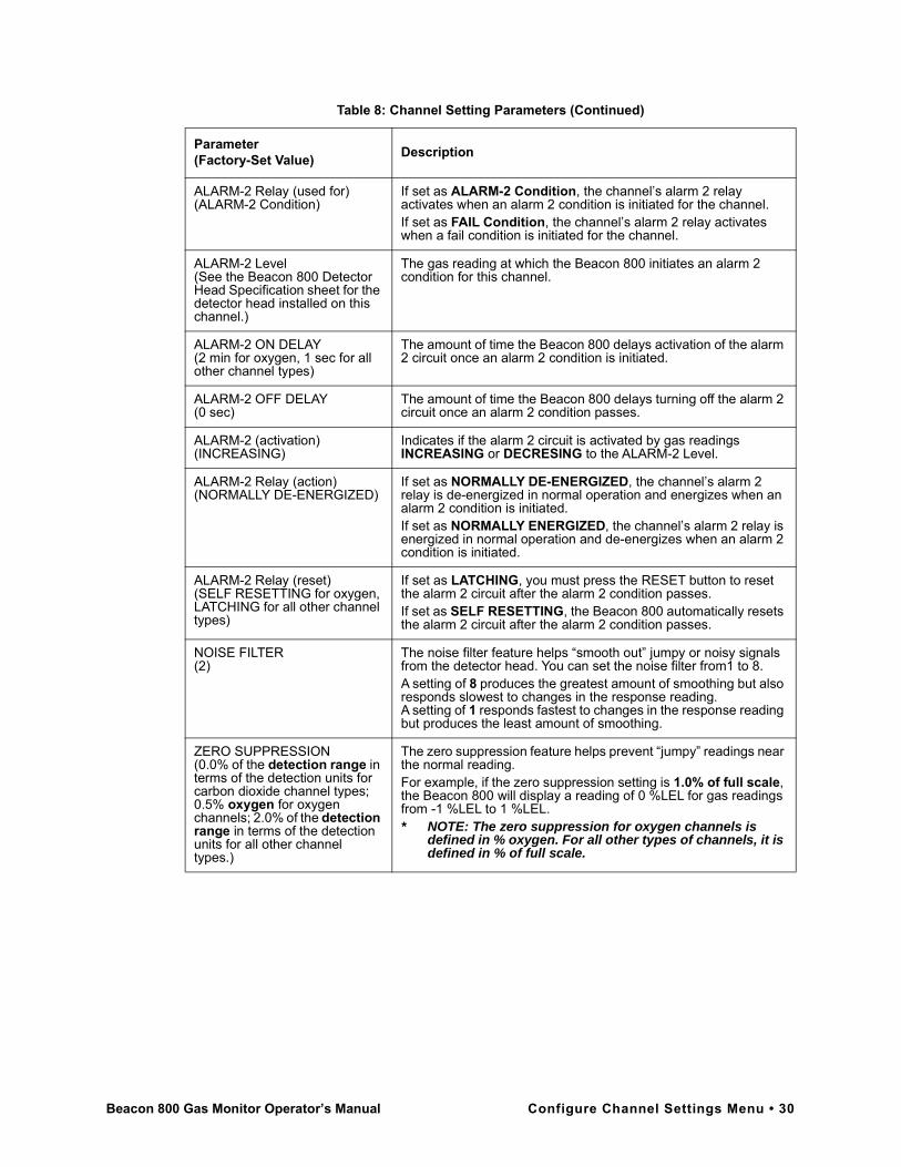
ALARM-2 Relay (used for)(ALARM-2 Condition)
If set as ALARM-2 Condition, the channel’s alarm 2 relay activates when an alarm 2 condition is initiated for the channel.If set as FAIL Condition, the channel’s alarm 2 relay activates when a fail condition is initiated for the channel.
ALARM-2 Level(See the Beacon 800 Detector Head Specification sheet for the detector head installed on this channel.)
The gas reading at which the Beacon 800 initiates an alarm 2 condition for this channel.
ALARM-2 ON DELAY(2 min for oxygen, 1 sec for all other channel types)
The amount of time the Beacon 800 delays activation of the alarm 2 circuit once an alarm 2 condition is initiated.
ALARM-2 OFF DELAY(0 sec)
The amount of time the Beacon 800 delays turning off the alarm 2 circuit once an alarm 2 condition passes.
ALARM-2 (activation)(INCREASING)
Indicates if the alarm 2 circuit is activated by gas readings INCREASING or DECRESING to the ALARM-2 Level.
ALARM-2 Relay (action)(NORMALLY DE-ENERGIZED)
If set as NORMALLY DE-ENERGIZED, the channel’s alarm 2 relay is de-energized in normal operation and energizes when an alarm 2 condition is initiated.If set as NORMALLY ENERGIZED, the channel’s alarm 2 relay is energized in normal operation and de-energizes when an alarm 2 condition is initiated.
ALARM-2 Relay (reset)(SELF RESETTING for oxygen, LATCHING for all other channel types)
If set as LATCHING, you must press the RESET button to reset the alarm 2 circuit after the alarm 2 condition passes.If set as SELF RESETTING, the Beacon 800 automatically resets the alarm 2 circuit after the alarm 2 condition passes.
NOISE FILTER(2)
The noise filter feature helps “smooth out” jumpy or noisy signals from the detector head. You can set the noise filter from1 to 8.A setting of 8 produces the greatest amount of smoothing but also responds slowest to changes in the response reading.A setting of 1 responds fastest to changes in the response reading but produces the least amount of smoothing.
ZERO SUPPRESSION(0.0% of the detection range in terms of the detection units for carbon dioxide channel types; 0.5% oxygen for oxygen channels; 2.0% of the detection range in terms of the detection units for all other channel types.)
The zero suppression feature helps prevent “jumpy” readings near the normal reading.For example, if the zero suppression setting is 1.0% of full scale, the Beacon 800 will display a reading of 0 %LEL for gas readings from -1 %LEL to 1 %LEL.* NOTE: The zero suppression for oxygen channels is
defined in % oxygen. For all other types of channels, it is defined in % of full scale.
Table 8: Channel Setting Parameters (Continued)
Parameter(Factory-Set Value) Description
Beacon 800 Gas Monitor Operator’s Manual Configure Channel Settings Menu • 30
Chapter 6: Maintenance
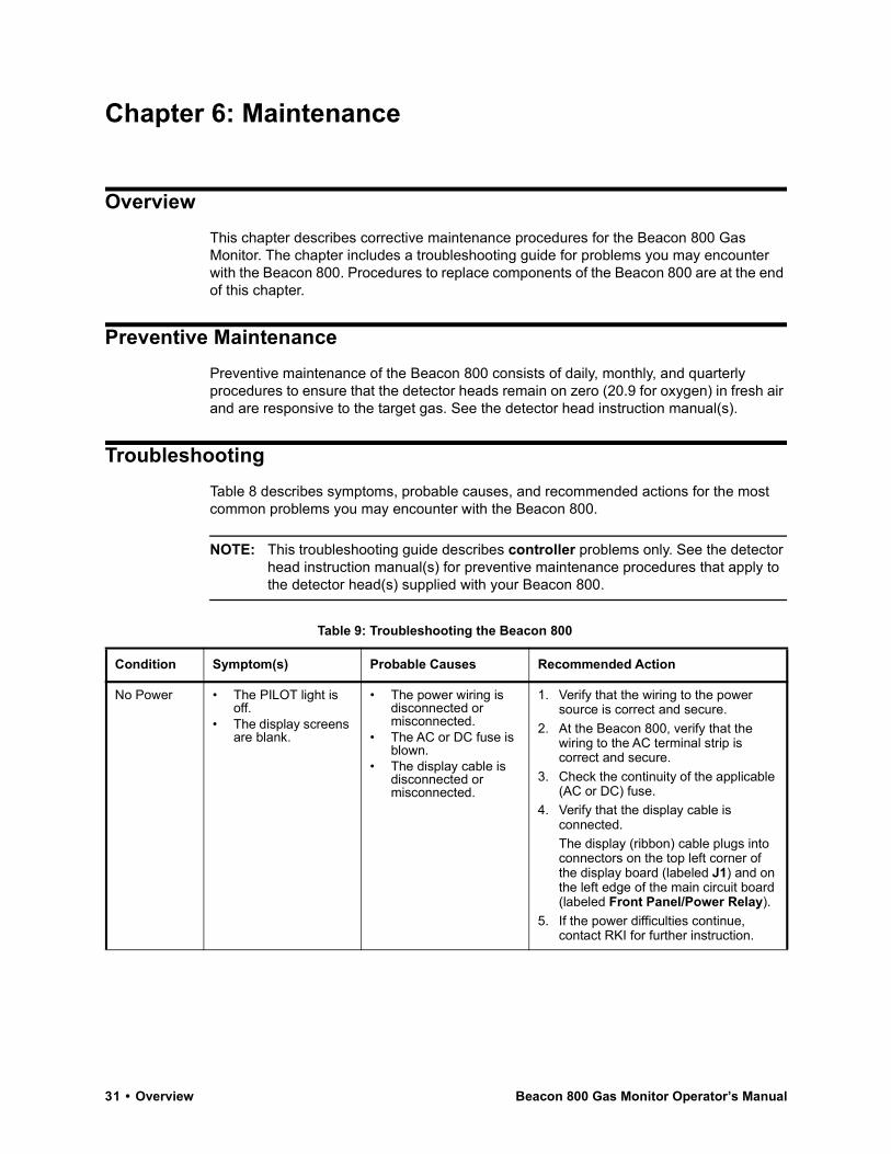
OverviewThis chapter describes corrective maintenance procedures for the Beacon 800 Gas Monitor. The chapter includes a troubleshooting guide for problems you may encounter with the Beacon 800. Procedures to replace components of the Beacon 800 are at the end of this chapter.
Preventive MaintenancePreventive maintenance of the Beacon 800 consists of daily, monthly, and quarterly procedures to ensure that the detector heads remain on zero (20.9 for oxygen) in fresh air and are responsive to the target gas. See the detector head instruction manual(s).
TroubleshootingTable 8 describes symptoms, probable causes, and recommended actions for the most common problems you may encounter with the Beacon 800.
NOTE: This troubleshooting guide describes controller problems only. See the detector head instruction manual(s) for preventive maintenance procedures that apply to the detector head(s) supplied with your Beacon 800.
Table 9: Troubleshooting the Beacon 800
Condition Symptom(s) Probable Causes Recommended Action
No Power • The PILOT light is off.
• The display screens are blank.
• The power wiring is disconnected or misconnected.
• The AC or DC fuse is blown.
• The display cable is disconnected or misconnected.
1. Verify that the wiring to the power source is correct and secure.
2. At the Beacon 800, verify that the wiring to the AC terminal strip is correct and secure.
3. Check the continuity of the applicable (AC or DC) fuse.
4. Verify that the display cable is connected.The display (ribbon) cable plugs into connectors on the top left corner of the display board (labeled J1) and on the left edge of the main circuit board (labeled Front Panel/Power Relay).
5. If the power difficulties continue, contact RKI for further instruction.
31 • Overview Beacon 800 Gas Monitor Operator’s Manual
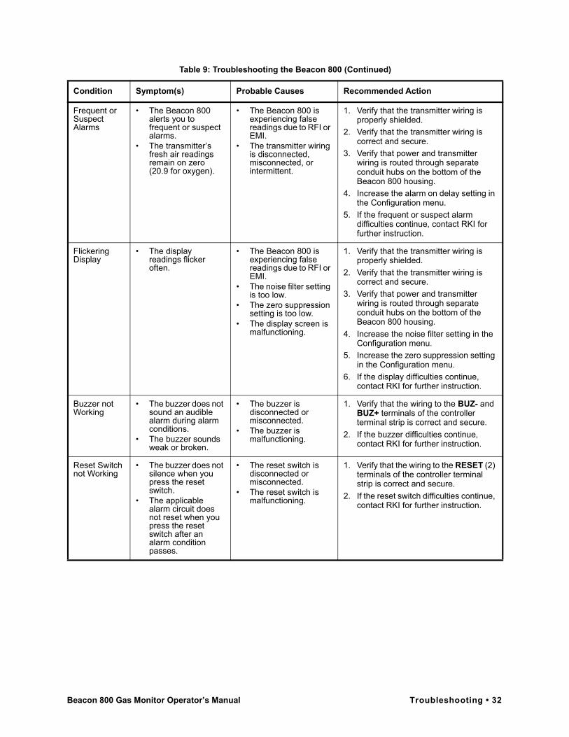
Frequent or Suspect Alarms
• The Beacon 800 alerts you to frequent or suspect alarms.
• The transmitter’s fresh air readings remain on zero(20.9 for oxygen).
• The Beacon 800 is experiencing false readings due to RFI or EMI.
• The transmitter wiring is disconnected, misconnected, or intermittent.
1. Verify that the transmitter wiring is properly shielded.
2. Verify that the transmitter wiring is correct and secure.
3. Verify that power and transmitter wiring is routed through separate conduit hubs on the bottom of the Beacon 800 housing.
4. Increase the alarm on delay setting in the Configuration menu.
5. If the frequent or suspect alarm difficulties continue, contact RKI for further instruction.
Flickering Display
• The display readings flicker often.
• The Beacon 800 is experiencing false readings due to RFI or EMI.
• The noise filter setting is too low.
• The zero suppression setting is too low.
• The display screen is malfunctioning.
1. Verify that the transmitter wiring is properly shielded.
2. Verify that the transmitter wiring is correct and secure.
3. Verify that power and transmitter wiring is routed through separate conduit hubs on the bottom of the Beacon 800 housing.
4. Increase the noise filter setting in the Configuration menu.
5. Increase the zero suppression setting in the Configuration menu.
6. If the display difficulties continue, contact RKI for further instruction.
Buzzer not Working
• The buzzer does not sound an audible alarm during alarm conditions.
• The buzzer sounds weak or broken.
• The buzzer is disconnected or misconnected.
• The buzzer is malfunctioning.
1. Verify that the wiring to the BUZ- and BUZ+ terminals of the controller terminal strip is correct and secure.
2. If the buzzer difficulties continue, contact RKI for further instruction.
Reset Switch not Working
• The buzzer does not silence when you press the reset switch.
• The applicable alarm circuit does not reset when you press the reset switch after an alarm condition passes.
• The reset switch is disconnected or misconnected.
• The reset switch is malfunctioning.
1. Verify that the wiring to the RESET (2) terminals of the controller terminal strip is correct and secure.
2. If the reset switch difficulties continue, contact RKI for further instruction.
Table 9: Troubleshooting the Beacon 800 (Continued)
Condition Symptom(s) Probable Causes Recommended Action
Beacon 800 Gas Monitor Operator’s Manual Troubleshooting • 32

Replacing the FusesThe Beacon 800 includes up to three fuses. This section applies to all three fuses. To replace other components of the Beacon 800, contact RKI Instruments, Inc. for further information.
1. Turn off or unplug all incoming power to the Beacon 800 at the power source end.
2. Open the housing door of the Beacon 800, then place the power switch in the OFF position. Loosen the two captive thumbscrews on the right side of the display board, until the thumbscrews are disengaged from the standoffs.
3. Pull the right side of the display board out toward the housing door. (The standoffs under the left side of the display board are hinged, which allow the display board to move in this manner.)
4. Use a flat-blade screwdriver to rotate the applicable fuse holder 1/4 turn counter clockwise. The fuse holder releases from the socket.
5. Remove the fuse holder from the socket, then remove the fuse from the fuse holder.
CAUTION: Verify that the replacement fuse is the same type and rating as the fuse you are replacing.
6. Install the appropriate replacement fuse in the fuse holder, then place the fuse holder in the socket.
7. Push the fuse holder into the socket, then turn the holder 1/4 turn clockwise to secure it in the socket.
8. Place the display board in its original position, then secure the board to the standoffs with the two screws you loosened in Step 2.
9. Plug in or turn on all incoming power to the Beacon 800 at the power source end.
10. Place the Beacon 800’s power switch in the ON position, then verify that the PILOT light is on.
11. Close and secure the housing door.
33 • Replacing the Fuses Beacon 800 Gas Monitor Operator’s Manual
Chapter 7: Optional Recorder Output Board& Heavy Duty Relay Board
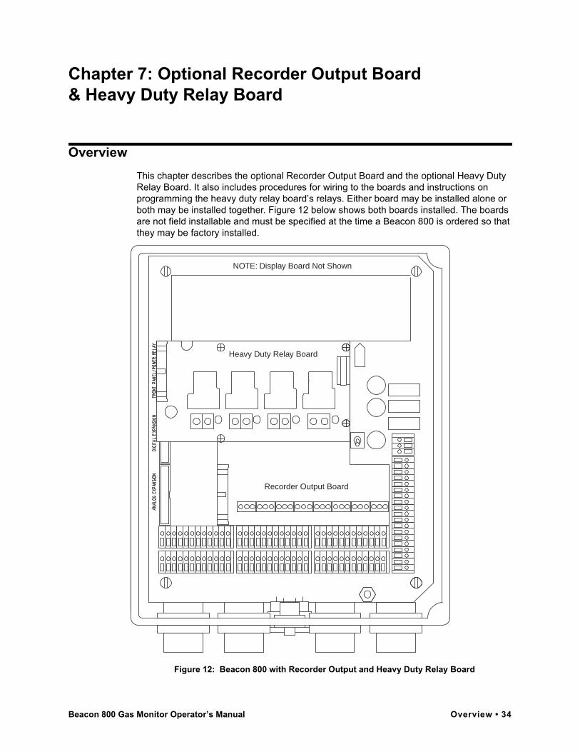
OverviewThis chapter describes the optional Recorder Output Board and the optional Heavy Duty Relay Board. It also includes procedures for wiring to the boards and instructions on programming the heavy duty relay board’s relays. Either board may be installed alone or both may be installed together. Figure 12 below shows both boards installed. The boards are not field installable and must be specified at the time a Beacon 800 is ordered so that they may be factory installed.
Figure 12: Beacon 800 with Recorder Output and Heavy Duty Relay Board
NOTE: Display Board Not Shown
Heavy Duty Relay Board
Recorder Output Board
Beacon 800 Gas Monitor Operator’s Manual Overview • 34
Recorder Output Board
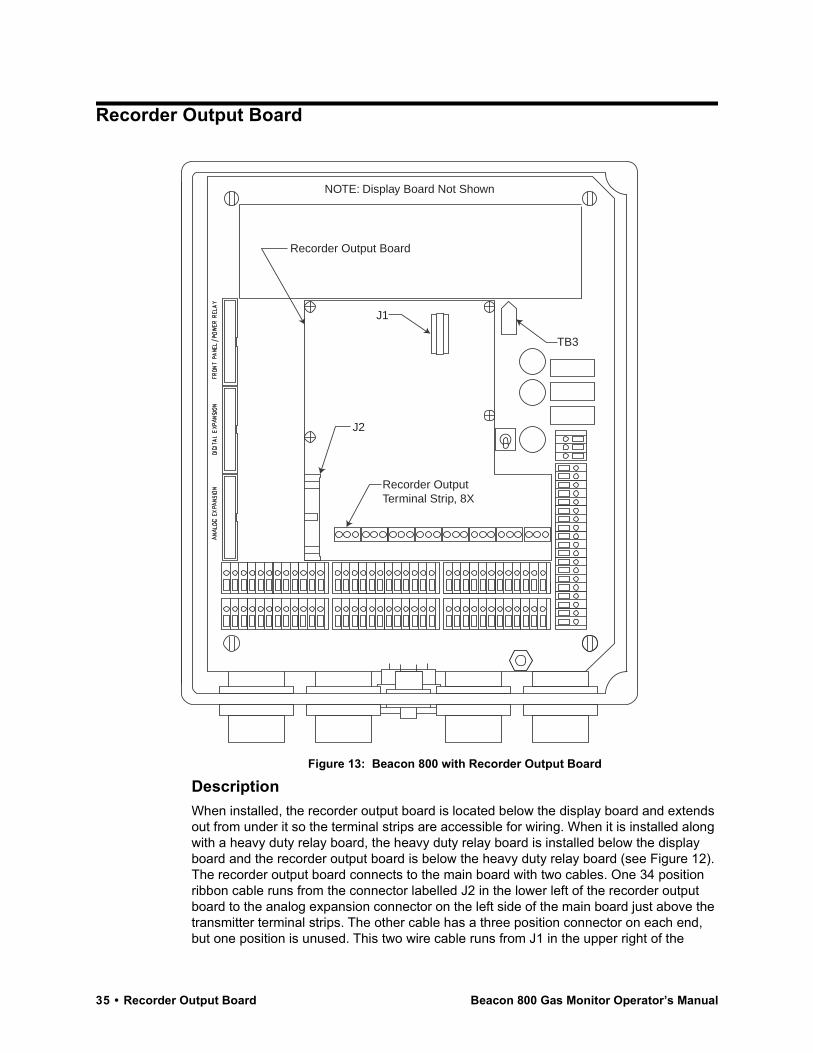
Figure 13: Beacon 800 with Recorder Output Board
DescriptionWhen installed, the recorder output board is located below the display board and extends out from under it so the terminal strips are accessible for wiring. When it is installed along with a heavy duty relay board, the heavy duty relay board is installed below the display board and the recorder output board is below the heavy duty relay board (see Figure 12). The recorder output board connects to the main board with two cables. One 34 position ribbon cable runs from the connector labelled J2 in the lower left of the recorder output board to the analog expansion connector on the left side of the main board just above the transmitter terminal strips. The other cable has a three position connector on each end, but one position is unused. This two wire cable runs from J1 in the upper right of the
Recorder OutputTerminal Strip, 8X
Recorder Output Board
J1
J2
TB3
NOTE: Display Board Not Shown
35 • Recorder Output Board Beacon 800 Gas Monitor Operator’s Manual

recorder output board to TB3 on the main board below the power supply. If the heavy duty relay board is also installed, this cable has an additional section which connects to TB5 on the heavy duty relay board.
The recorder output board provides a two linear analog signal outputs for each active channel, giving the reading for the channel. They are a current output and a voltage output: 4-20 mA (milliamps) and 1-5 V (volts). Either one or both may be monitored by a chart recorder or any other appropriate device. A current monitoring device must have have 500 ohms resistance maximum and a voltage monitoring device must have 500 ohms resistance minimum.
WiringPerform the following procedure to connect a recording device to the recorder output board.
1. Turn off Power to the Beacon 800 at the power source.
2. Open the Beacon 800 door and place the power switch in the off position.
3. Install an appropriately rated cable bushing or conduit in an unused conduit hub on the bottom of the Beacon 800 housing.
4. Route wires in conduit or shielded cable from the recording device through the selected conduit hub into the Beacon 800.
When wiring to the 4 - 20 mA output, keep in mind that the maximum allowable resistance including the current monitoring device and wiring can be no greater than 500 ohms.
When wiring to the 1 - 5 V output, keep in mind that the minimum allowable resistance of the voltage monitoring device and wiring is 500 ohms.
5. Connect the wires to the recorder output board as illustrated in Figure 14. See the monitoring device’s instruction manual for connections at the monitoring device.
Figure 14: Recorder Output Board Wiring
Typical Wiring
CurrentMonitoring
Device
VoltageMonitoring
Device
CurrentMonitoring
Device
VoltageMonitoring
Device
Optional Wiring for Simultaneous Monitoring ofCurrent and Voltage Output
Recorder Output Board(Installed in Beacon 800)
J2
Beacon 800 Gas Monitor Operator’s Manual Recorder Output Board • 36

6. Start up the Beacon 800 as described in “Chapter 3: Installation and Start Up” on page 9. When the Beacon 800 start up is complete, the recorder output board will be generating the analog output signals for all active channels.
OperationThe output of the board for a channel directly mirrors the signal from the detector head installed on that channel at all times regardless of whether the Beacon 800 is in normal operation or in the configuration menu. 4 mA and 1 V correspond to a gas concentration of 0; 20 mA and 5 V correspond to a full scale reading. In the case of an oxygen channel, a normal concentration of oxygen, 20.9%, corresponds to 17.38 mA and 4.34 V. The output at terminals for any inactive or uninstalled channels is 0 mA and 0 V.
37 • Recorder Output Board Beacon 800 Gas Monitor Operator’s Manual

Heavy Duty Relay Board
Figure 15: Beacon 800 with Heavy Duty Relay Board
DescriptionWhen installed, the heavy duty relay board is located below the display board. The terminals are not accessible unless the display board, which is hinged on its left side, is swung open. If the heavy duty relay board is installed with a recorder output board, it is located below the display board and above the recorder output board (see Figure 12). The heavy duty relay board connects to the main board with two cables. One 34 position ribbon cable runs from the connector labelled J1 in the upper left of the heavy duty relay board to the analog front panel/power relay connector on the left side of the main board
J1Heavy Duty Relay Terminal Strip, 4X
Energized Relay Indication LED, 4X
Heavy Duty Relay Board
TB5
TB3
NOTE: Display Board Not Shown
Beacon 800 Gas Monitor Operator’s Manual Heavy Duty Relay Board • 38
and to J1 on the upper left of the display board. The other cable has a three position connector on each end, but one position is unused. This two wire cable runs from TB5 in the upper right of the heavy duty relay board to TB3 on the main board below the power supply. If the recorder output board is also installed, this cable has an additional section which connects to J1 on the recorder output board.
The heavy duty relay board provides four extra sets of relay contacts which can be used to control devices drawing too much current to use the Beacon 800’s standard relay contacts. The four relay contact terminal strips are located along the bottom of the heavy duty relay board. An LED is located just to the right of each terminal strip which indicates when that relay is energized. The relay contacts are rated 30 A at 240 VAC, and 30 A at 125 VAC. A typical use for the heavy duty relay board is controlling ventilation fans in a parking garage.
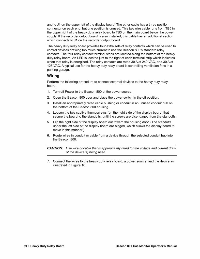
WiringPerform the following procedure to connect external devices to the heavy duty relay board.
1. Turn off Power to the Beacon 800 at the power source.
2. Open the Beacon 800 door and place the power switch in the off position.
3. Install an appropriately rated cable bushing or conduit in an unused conduit hub on the bottom of the Beacon 800 housing.
4. Loosen the two captive thumbscrews (on the right side of the display board) that secure the board to the standoffs, until the screws are disengaged from the standoffs.
5. Flip the right side of the display board out toward the housing door. (The standoffs under the left side of the display board are hinged, which allows the display board to move in this manner.)
6. Route wires in conduit or cable from a device through the selected conduit hub into the Beacon 800.
CAUTION: Use wire or cable that is appropriately rated for the voltage and current draw of the device(s) being used.
7. Connect the wires to the heavy duty relay board, a power source, and the device as illustrated in Figure 16.
39 • Heavy Duty Relay Board Beacon 800 Gas Monitor Operator’s Manual

Figure 16: Wiring the Heavy Duty Relay Board
8. Rotate the display board back to its original position and secure it to the standoffs with the two thumbscrews.
9. Start up the Beacon 800 as described in Chapter 3.
OperationUnlike the Beacon 800’s standard relay contacts which are form C (common, normally open, and normally closed contacts) the heavy duty relays are form A (common and normally open). Form A contacts are open when the relay is de-energized.
The alarm conditions under which the heavy duty relays activate are programmed in the Configuration Menu (see below). When an alarm condition occurs which has been defined to cause a particular relay to activate, the relay contacts will change condition. They will either open or close depending on how the relay is programmed.
NOTE: The LED to the right of each contact terminal strip indicates when the relay is energized and the contacts are closed, not when an alarm condition has occurred. If a relay is programmed to be normally energized, then the LED for that relay will be on during normal non-alarm operation and turn off if the appropriate alarm condition occurs to activate that relay.
If a relay is programmed to be NDE (normally de-energized), the contacts are open and the LED for that relay is off during non-alarm operation. If the appropriate alarm condition occurs, the contacts are closed and the LED is on.
If a relay is programmed to be NE (normally energized), the contacts are closed and the LED for that relay is on during non-alarm operation. If the appropriate alarm condition occurs, the contacts are open and the LED is off.
Heavy Duty Relay Board(Installed in Beacon 800)
1 2 3 4
TB5
Alarm Device Power
Alarm Devices
Beacon 800 Gas Monitor Operator’s Manual Heavy Duty Relay Board • 40
Programming the Heavy Duty RelaysThe heavy duty relays are programmed in the Configuration menu. The following relay conditions may be programmed:
• enabled or disabled
• normally de-energized (NDE) or normally energized (NE)
• conditions under which a relay activates
The Configure Power Relays menu item is displayed in the Configuration menu only if the heavy duty relay board is installed in the Beacon 800.
Entering the Configuration Menu
1. To enter the Configuration menu, simultaneously press and hold the ESCAPE and ENTER buttons for approximately 5 seconds. Release the buttons when the You Have Entered the Configuration Menu... message appears on the top display screen.
NOTE: The Configuration menu includes a 5-minute time-out feature. If you do not perform an action within 5 minutes of the previous action, the Beacon 800 automatically returns to normal operation.
2. Press the UP (YES) button to continue.3. Press the UP (YES) or DOWN (NO) button until the 4) Configure Power Relays
message appears on the bottom display screen, then press the ENTER button to continue.
Programming the Relays
1. The top screen will prompt you to select a relay to program.Select a relay to program using the UP (YES) and DOWN (NO) buttons. You may select from four relays. After selecting the relay, press ENTER.
2. The top screen will display whether the selected relay is currently ENABLED or DISABLED. If the relay is set to ENABLED, it will operated as programmed. If it is set to DISABLED, it will not operate and the relay contacts for the selected relay will always be open. If the current setting is OK, press UP (YES) to continue.If you want to change the current setting, press DOWN (NO). Use the UP (YES) and DOWN (NO) buttons to change the setting. After selecting the setting, press ENTER to continue.
3. The top screen will display whether the relay is currently set to be NORMALLY ENERGIZED or NORMALLY DE-ENERGIZED. If the current setting is OK, press UP (YES) to continue.
If you want to change the current setting, press DOWN (NO). Use the UP (YES) and DOWN (NO) buttons to change the setting. After selecting the setting, press ENTER to continue.
4. The bottom screen will indicate the conditions under which the relay is currently programmed to activate.
A grid on the lower screen will define the alarm conditions under which the relay will activate. The grid’s rows indicate which alarm condition will cause the relay to activate: FAIL, ALARM-1, or ALARM-2. The grid’s columns indicate on which channel(s) the alarm level(s) must occur for the relay to activate.
41 • Heavy Duty Relay Board Beacon 800 Gas Monitor Operator’s Manual

Figure 17: Heavy Duty Relay Programming Grid
A minus sign (-) in a grid position indicates that the condition on that channel will not cause this relay to activate. A plus sign (+) in a grid position indicates that the condition on that channel will cause the relay to activate. If one or more conditions marked with a (+) occur during normal operation, the relay will activate. Figure 17 above shows a typical relay programming grid. In the example shown, the selected relay will activate if any or all of the following conditions occurs:
• Channel 1 experiences a Fail condition.
• Channel 4 experiences an Alarm 1 condition.
• Channel 8 experiences an Alarm 2 condition.
If the relay activation settings are OK, press the UP (YES) button, then press UP (YES) to save all the relay settings or DOWN (NO) to abort any setting changes. Skip to step 5.
If you want to change the activation conditions, press the DOWN (NO) button and a flashing cursor will appear in the ALARM-2/Channel 1 grid position (row 1/column 1).
• Use the ENTER and ESCAPE buttons to move the flashing cursor to the grid posi-tion(s) you want to change.
• Use the UP (YES) button to insert a + in a grid position and the DOWN (NO) but-ton to insert a - in a grid position.
• When you are done changing the settings, press the ENTER button until the flash-ing cursor is on the FAIL/CHannel 8 grid position, then press the ENTER button again.
• If the settings are OK, press UP (YES) to save them. The top display screen will indicate that the setting are being saved.
If the settings are not OK, press DOWN (NO).
5. The top screen prompts you to select another relay to program. To program another relay, select the relay and repeat steps 1 through 4. If you are done programming relays, press ESCAPE twice and then DOWN (NO) to return to normal operation.
A L A R M - 2 : - - - - - - - +C h a n n e l - 1 2 3 4 5 6 7 8
A L A R M - 1 : - - - + - - - -F A I L : + - - - - - - -
Beacon 800 Gas Monitor Operator’s Manual Heavy Duty Relay Board • 42

Parts ListTable 10 lists the part numbers and descriptions for replacement parts and accessories offered for the Beacon 800 Gas Monitor.
Table 10: Parts List, Beacon 800 Gas Monitor
Part No. Description
18-0107RK Conduit Hub (3/4 in.)
43-0440RK Reset Switch
43-4165RK AC Fuse (3A)
43-4170RK DC Fuse (6A)
52-1016RK Buzzer
71-0037RK Beacon 800 Gas Monitor Operator’s Manual (this document)
43 • Parts List Beacon 800 Gas Monitor Operator’s Manual