Embed Size (px)
Citation preview

Beamforming for Fully-OverlappedTwo-Dimensional Phased-MIMO Radar
Anastasios Deligiannis, Sangarapillai LambotharanSchool of Electronic, Electrical and Systems EngineeringLoughborough University, Leicestershire, UK, LE11 3TU
Emails: {A.Deligiannis, S.Lambotharan}@lboro.ac.uk
Jonathon A. ChambersDepartment of Electronic Engineering
University of Surrey, Guildford, UK, GU2 7XHEmail: [email protected]
Abstract—We investigate the design of joint transmitter and re-ceiver beamformer within the context of multiple-input multiple-output (MIMO) radar employing two-dimensional (2D) arrays ofantennas. Specifically, we derive the transmit, waveform diversityand overall transmit-receive beampatterns for the Phased-MIMOradar with fully-overlapped subarrays and compare them withthe respective beampatterns for the Phased-array and MIMOradar only schemes. As reported for one-dimensional lineararrays, fully-overlapped 2D subarrays offer substantial improve-ments in performance as compared with the phased-array andMIMO only radar models. The work considers both the adaptive(convex optimization, CAPON beamformer) and non-adaptive(conventional) beamforming techniques. The simulation resultsdemonstrate the superiority of the fully-overlapped subapertur-ing in both cases.
I. INTRODUCTION
The field of radar research is vast and has been endlesslydeveloping since late 1930’s. The gigantic breakthroughs indigital signal processing and the constant growth in com-putational capabilities have enabled the introduction of anemerging technology known as multiple-input multiple-output(MIMO) radar [1]. The essence of MIMO radar is the use ofmultiple antennas to simultaneously transmit diverse, possiblylinearly independent waveforms, in contrast to a phased-arrayradar which transmits scaled versions of a single waveform.This waveform diversity offers superior capabilities as com-pared to the phased-array model. There are two fundamentalregimes of operation investigated in the literature. In the firsttype, the transmit and receive antenna elements are widelyspaced, whereas, in the second type, the antenna elements areclosely spaced.
MIMO radar with colocated antennas [2] is known to offerhigher sensitivity to detect slowly moving targets, higherangular resolution, increased number of detectable targets,direct applicability of adaptive array techniques and betterparameter identifiability. On the other hand, MIMO radar withwidely spaced antennas provides the ability to capture thespatial diversity of the target’s radar cross section (RCS),enhance the ability to combat signal scintillation, estimateprecisely the parameters of fast moving targets and improvethe target detection performance, by taking advantage of thetarget’s geometrical characteristics [3].
The substantial improvements offered by MIMO radartechnology come at the cost of losing the transmit coherent
processing gain offered by phased-array radar [4], [6]. Thisabsence can lead to signal-to-noise ratio (SNR) decrease andbeam-shape loss [4], [6]. The aforementioned disadvantagesraise the dilemma of whether or not MIMO radar will meetthe expectations that it will provide a colossal opportunity forimprovements in the field of radar research. This work stemsfrom the belief that MIMO radar is not a substitute technologythat will totally outclass phased-array radars, but rather itprovides the opportunity of jointly exploiting the benefits ofboth models, as reported recently in the literature [6], [8].The authors of [8] proposed a radar model, utilizing theidea of dividing a large number of colocated transmit/receiveelements into multiple subarrays, that are not allowed tooverlap. Phased-MIMO radar is a breakthrough notion inradar technology, introduced in [6]. The vantage point of thistechnique is the partition of the transmit array into subarraysthat are allowed to overlap. Our earlier work in [7] investigatedthe application of this Phased-MIMO radar notion to 2Dtransmit arrays by designing the transmit beampattern througha convex optimization problem that minimizes the differencebetween a desired transmit beampattern and the actual oneproduced by the system [1].
In this paper, we examine transmit, waveform diversityand overall transmit-receive beamforming design for Phased-MIMO radar with fully-overlapped 2D transmit subarrays.We design the Phased-MIMO beampatterns using both con-ventional and adaptive techniques and compare them withthe respective beampatterns of the phased-array and MIMOradars. Specifically, in order to design the adaptive transmitbeampattern, we solve a convex optimization problem thatminimizes the difference between a desired transmit beampat-tern and the actual one produced by the system. Furthermore,we obtain the adaptive overall transmit-receive beampatternby utilizing the Minimum Variance Distortionless Response(MVDR) Capon beamformer. The simulation results highlightthe benefits provided by the 2D Phased-MIMO radar with fullyoverlapped subarrays.
II. 2D PHASED-MIMO SYSTEM MODEL
We consider a monostatic radar system employing a uni-form rectangular array (URA), which consist of Mt × Ntand Mr × Nr antennas at the transmitter and the receiverrespectfully, where Mt and Mr are the number of elements
978-1-4799-8232-5/151$31.00@2015IEEE 0599

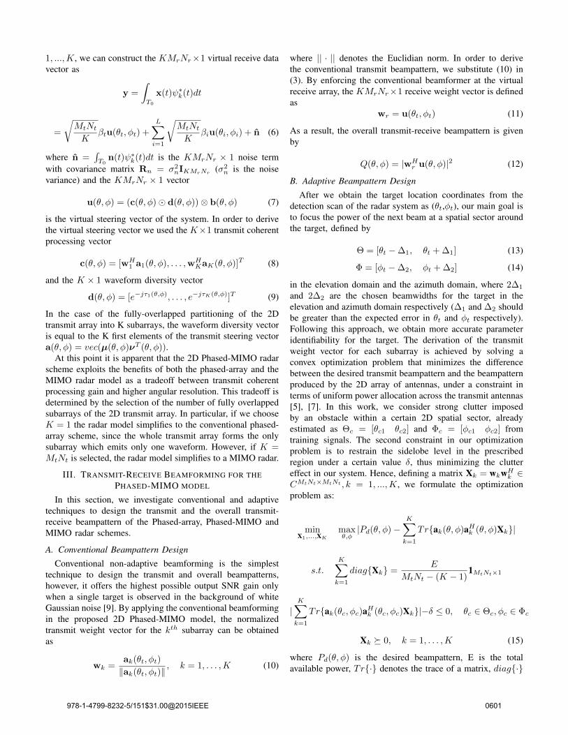
Fig. 1: Fully overlapped subaperturing of a 5 × 5 uniformrectangular array (URA) when K=4.
in each column and Nt and Nr are the number of antennasin each row of the planar arrays. The 2D Phased-MIMOmodel is based on partitioning the transmit 2D array into Ksubarrays (1 ≤ K ≤ Mt ×Nt) that are fully overlapped [6],as depicted in Fig.1, where a subaperturing of a 5×5 transmitURA into 4 subarrays is presented. Moreover the kth subarrayis composed of Mt × Nt − K + 1 antennas and emits thekth element of the predesigned independent waveform vectorψ(t) = [ψ1(t), . . . , ψK(t)]T of size K×1, which satisfies theorthogonality condition
∫T0ψ(t)ψH(t)dt = IK , where (·)T
denotes the transpose, t refers to the time index within theradar pulse, T0 is the radar pulse width, IK is the K × Kidentity matrix, and (·)H denotes the Hermitian transpose.
In order to characterize the fully overlapped subaperturingof the 2D Phased-MIMO model mathematically, we introducean Mt ×Nt selection matrix Zk [5]. When the (mn)th entryequals 1 then the (mn)th element of the 2D array belongs tothe kth subarray, while a 0 entry in Zk means that the elementis not a part of the kth subarray. Thus, the matrix Zk definesthe structure of the kth subarray. As a result, the MtNt × 1transmit steering vector related to the kth subarray can beconstructed as:
ak(θ, φ) = vec(Zk � [µ(θ, φ)νT (θ, φ)]) (1)
where vec(·) is the operator that stacks the columns of a matrixinto one column vector, � denotes the Hadamard product, θand φ denote the elevation and azimuth angles respectively.The auxiliary vectors µ(θ, φ) ∈ CMt×1 and ν(θ, φ) ∈ CNt×1
are derived from the array geometry and they are defined asfollows:
µ(θ, φ) = [1, ej2πdmsin(θ)cos(φ), . . . , ej2π(Mt−1)dmsin(θ)cos(φ)]T
ν(θ, φ) = [1, ej2πdnsin(θ)sin(φ), . . . , ej2π(Nt−1)dnsin(θ)sin(φ)]T
where dm and dn are the distances between the adjacentantennas at each column and at each row respectively.
Our primary objective is to focus the transmit energy onto acertain 2D sector in space, determined by the direction of thetarget, and at the same time to achieve high transmit coherentprocessing gain. Hence, a weight vector should be designedfor each of the K subarrays to steer the transmit beam in thedesired spatial sector. The MtNt× 1 vector which consists ofthe complex envelope of the signals at the output of the kth
subarray can be modeled as sk(t) =√
MtNt
K wkψk(t), wherewk ∈ CMtNt×1 is the transmit beamformer weight vector,used to form the kth transmit beam. The power of the emittedsignal from the kth subarray focused at a generic focal pointwith coordinates (θ, φ) is given by
Pk(θ, φ) = aHk (θ, φ)E{sk(t)sHk (t)}ak(θ, φ)
=MtNtK
aHk (θ, φ)wkwHk ak(θ, φ) (2)
Using the far field assumption and adding the power of theprobing signals emitted by all K subarrays, we write the 2Darray transmit beampattern as
P (θ, φ) =
K∑k=1
MtNtK
aHk (θ, φ)wkwHk ak(θ, φ) (3)
Assuming that there is a target present in the far-field ofthe transmit and receive arrays at direction θt in the elevationdomain and φt in the azimuth domain, the signal reflected bythe aforementioned target is modeled as
r(t, θt, φt) =
√MtNtK
βt
K∑k=1
wHk ak(θt, φt)e−jτk(θt,φt)ψk(t)
(4)where βt is the complex amplitude proportional to the radarcross section (RCS) of the target, and τk(θt, φt) is the timerequired for the signal to cover the distance between the firstelement of the transmit array and the first element of the kth
subarray.If we assume that in addition to the desired target, there are
L active interfering targets at locations {θi}Li=1, {φi}Li=1 andwith reflection coefficients {βi}Li=1, then under the simplifyingassumption of point targets, the MrNr×1 received data vectorcan be described by the equation
x(t) = r(t, θt, φt)b(θt, φt) +
L∑i=1
r(t, θi, φi)b(θi, φi) + n(t)
(5)where b(θ, φ) is the MrNr×1 steering vector of the receivedarray and n(t) is the noise component that is supposed tohave zero mean. By applying matched filtering to the receiveddata vector for each of the orthogonal waveforms ψk(t), k =
978-1-4799-8232-5/151$31.00@2015IEEE 0600
1, ...,K, we can construct the KMrNr×1 virtual receive datavector as
y =
∫T0
x(t)ψ∗k(t)dt
=
√MtNtK
βtu(θt, φt) +L∑i=1
√MtNtK
βiu(θi, φi) + n̂ (6)
where n̂ =∫T0
n(t)ψ∗k(t)dt is the KMrNr × 1 noise term
with covariance matrix Rn = σ2nIKMrNr
(σ2n is the noise
variance) and the KMrNr × 1 vector
u(θ, φ) = (c(θ, φ)� d(θ, φ))⊗ b(θ, φ) (7)
is the virtual steering vector of the system. In order to derivethe virtual steering vector we used the K×1 transmit coherentprocessing vector
c(θ, φ) = [wH1 a1(θ, φ), . . . ,wH
KaK(θ, φ)]T (8)
and the K × 1 waveform diversity vector
d(θ, φ) = [e−jτ1(θ,φ), . . . , e−jτK(θ,φ)]T (9)
In the case of the fully-overlapped partitioning of the 2Dtransmit array into K subarrays, the waveform diversity vectoris equal to the K first elements of the transmit steering vectora(θ, φ) = vec(µ(θ, φ)νT (θ, φ)).
At this point it is apparent that the 2D Phased-MIMO radarscheme exploits the benefits of both the phased-array and theMIMO radar model as a tradeoff between transmit coherentprocessing gain and higher angular resolution. This tradeoff isdetermined by the selection of the number of fully overlappedsubarrays of the 2D transmit array. In particular, if we chooseK = 1 the radar model simplifies to the conventional phased-array scheme, since the whole transmit array forms the onlysubarray which emits only one waveform. However, if K =MtNt is selected, the radar model simplifies to a MIMO radar.
III. TRANSMIT-RECEIVE BEAMFORMING FOR THEPHASED-MIMO MODEL
In this section, we investigate conventional and adaptivetechniques to design the transmit and the overall transmit-receive beampattern of the Phased-array, Phased-MIMO andMIMO radar schemes.
A. Conventional Beampattern Design
Conventional non-adaptive beamforming is the simplesttechnique to design the transmit and overall beampatterns,however, it offers the highest possible output SNR gain onlywhen a single target is observed in the background of whiteGaussian noise [9]. By applying the conventional beamformingin the proposed 2D Phased-MIMO model, the normalizedtransmit weight vector for the kth subarray can be obtainedas
wk =ak(θt, φt)
‖ak(θt, φt)‖, k = 1, . . . ,K (10)
where || · || denotes the Euclidian norm. In order to derivethe conventional transmit beampattern, we substitute (10) in(3). By enforcing the conventional beamformer at the virtualreceive array, the KMrNr×1 receive weight vector is definedas
wr = u(θt, φt) (11)
As a result, the overall transmit-receive beampattern is givenby
Q(θ, φ) = |wHr u(θ, φ)|2 (12)
B. Adaptive Beampattern Design
After we obtain the target location coordinates from thedetection scan of the radar system as (θt,φt), our main goal isto focus the power of the next beam at a spatial sector aroundthe target, defined by
Θ = [θt −∆1, θt + ∆1] (13)
Φ = [φt −∆2, φt + ∆2] (14)
in the elevation domain and the azimuth domain, where 2∆1
and 2∆2 are the chosen beamwidths for the target in theelevation and azimuth domain respectively (∆1 and ∆2 shouldbe greater than the expected error in θt and φt respectively).Following this approach, we obtain more accurate parameteridentifiability for the target. The derivation of the transmitweight vector for each subarray is achieved by solving aconvex optimization problem that minimizes the differencebetween the desired transmit beampattern and the beampatternproduced by the 2D array of antennas, under a constraint interms of uniform power allocation across the transmit antennas[5], [7]. In this work, we consider strong clutter imposedby an obstacle within a certain 2D spatial sector, alreadyestimated as Θc = [θc1 θc2] and Φc = [φc1 φc2] fromtraining signals. The second constraint in our optimizationproblem is to restrain the sidelobe level in the prescribedregion under a certain value δ, thus minimizing the cluttereffect in our system. Hence, defining a matrix Xk = wkwHk ∈CMtNt×MtNt , k = 1, ...,K, we formulate the optimizationproblem as:
minX1,...,XK
maxθ,φ|Pd(θ, φ)−
K∑k=1
Tr{ak(θ, φ)aHk (θ, φ)Xk}|
s.t.K∑k=1
diag{Xk} =E
MtNt − (K − 1)1MtNt×1
|K∑k=1
Tr{ak(θc, φc)aHk (θc, φc)Xk}|−δ ≤ 0, θc ∈ Θc, φc ∈ Φc
Xk � 0, k = 1, . . . ,K (15)
where Pd(θ, φ) is the desired beampattern, E is the totalavailable power, Tr{·} denotes the trace of a matrix, diag{·}
978-1-4799-8232-5/151$31.00@2015IEEE 0601

denotes the diagonal of a square matrix and 1MtNtdefines the
MtNt× 1 vector of ones. We use Xk � 0, k = 1, . . . ,K toindicate that Xk is positive semidefinite. The convex optimiza-tion problem (15) is solved using semidefinite programming(SDP) [10]. After obtaining the optimal solution, denoted asX∗k, we derive the optimal transmit weight vectors wk. If
X∗k is of rank one, which is the ideal scenario, the optimal
weight vector wk is obtained straightforwardly as the principaleigenvector of X∗
k multiplied by the square root of the principaleigenvalue of X∗
k. However, if the rank of X∗k is greater
than one, we resort to randomization techniques to obtain theoptimal transmit weight vectors [7].
Besides the transmit array, it is also important to useadaptive techniques at the 2D receive array of the system inorder to maximize the output signal to interference plus noiseratio (SINR). A beamformer that satisfies both the steeringcapabilities whereby the target signal is always protected andthe cancellation of interference so that the output SINR ismaximized, is the Minimum Variance Distortionless Response(MVDR) beamformer [11]. The main idea of the MVDRbeamformer is to minimize the covariance of the beamformeroutput subject to a distortionless response towards the directionof the target. Hence, it can be formulated as the followingoptimization problem
minwr
wHr R̂yywr subject to wH
r u(θt, φt) = 1 (16)
where R̂yy = 1N yyH is the sample covariance matrix of the
observed data samples that can be collected from N differentradar pulses. The solution to (16) is [11],
wr =R̂−1yy u(θt, φt)
uH(θt, φt)R̂−1yy u(θt, φt)
(17)
The receive weight vectors derived by (17) are employedto design the overall transmit-receive beampattern in oursimulations.
IV. SIMULATION RESULTS
We compare the performance of the fully-overlapped 2DPhased-MIMO radar to the phased-array and the conventionalMIMO radar schemes. We assume a 5 × 5 transmit-receiveURA with half-wavelength spacing between adjoining anten-nas (dm = dn = λ/2, where λ is the wavelength). Theemitted orthogonal baseband waveforms from each subarrayare modeled as [12]:
ψk(t) =
√1
T0ej2π(k/T0)t, k = 1, . . . ,K
The target we wish to detect is located at directions θt = −30o
and φt = 60o. Furthermore, we assume one interfering targetat directions θi = 30o and φi = 90o. The 2D transmit arrayis divided into 5 subarrays that are fully overlapped and eachof them consists of 21 antennas. The noise is considered ascomplex Gaussian with zero mean and variance 0.1. In order
to derive the sample covariance matrix we use N = 100 datasamples.
In the first example, we use the conventional non-adaptivebeamformer to derive both the transmit and receive weightvectors. In order to obtain the waveform diversity beampattern,we consider the waveform diversity vector obtained by (9) asthe weight vector. As a result, the transmit, the waveformdiversity and the overall beampatterns for the 2D Phased-MIMO radar are depicted in Fig. 2. In Fig. 3, we simulatethe same beampatterns for the phased-array radar model, byconsidering the whole 2D transmit array as the only subarray(K = 1). On the contrary, in order to simulate the conventionalMIMO radar, we set K = MtNt (each antenna of thetransmit array is considered as a subarray) and the respectivebeampatterns are shown in Fig. 4. To facilitate the comparisonbetween the three models, Figs. 5-7 show the cross sectionplotted against the elevation angle by keeping the azimuthangle constant at 60o as well as the cross section plottedagainst the azimuth angle by holding the elevation angle at−30o for all three schemes.
(a) Conventional transmit beam-pattern (dB).
(b) Conventional waveform diver-sity beampattern (dB).
(c) Conventional overall beampat-tern (dB).
Fig. 2: The beampatterns for the non-adaptive 2D Phased-MIMO radar.
As reported for the case of the one-dimensional (1D) lineararray in [6], for the 2D array also it is evident from Figs. 5 and6 that although the phased-array radar has the most efficienttransmit conventional beampattern due to its high transmitcoherent processing gain, it has zero waveform diversity gain.On the other hand, the MIMO radar has flat (0dB) transmitbeampattern, but it has the most accurate waveform diversitybeampattern, because of the simultaneous emission of MtNtorthogonal waveforms. However, it is clear from Fig. 7 that the2D Phased-MIMO radar remarkably outperforms the phased-array and MIMO radars in terms of the overall transmit-receivebeampattern, as it has lower sidelobes and approximates better
978-1-4799-8232-5/151$31.00@2015IEEE 0602

(a) Conventional transmit beam-pattern (dB).
(b) Conventional waveform diver-sity beampattern (dB).
(c) Conventional overall beampat-tern (dB).
Fig. 3: The beampatterns for the non-adaptive 2D phased-arrayradar.
(a) Conventional transmit beam-pattern (dB).
(b) Conventional waveform diver-sity beampattern (dB).
(c) Conventional overall beampat-tern (dB).
Fig. 4: The beampatterns for the non-adaptive 2D MIMO radar.
the desired target direction. Moreover, it is important tohighlight that in the case of conventional beamforming theoverall beampatterns of the phased-array and the MIMO radarare exactly the same.
In the second example, we employ adaptive beamformingtechniques to derive the transmit and receive beampatterns.In particular, we use convex optimization techniques to de-termine the transmit beamformer weight vectors and theMVDR (CAPON) based receiver beamformer for the receive
(a) Elevation cross section. (b) Azimuth cross section.
Fig. 5: Cross sections of the transmit beampattern at φ = 60o
and θ = −30o, respectively.
(a) Elevation cross section. (b) Azimuth cross section.
Fig. 6: Cross sections of the waveform diversity beampatternat φ = 60o and θ = −30o, respectively.
weight vectors. In our simulations we assume strong clutterat the 2D spatial sector defined by Θc = [−90o,−60o]and Φc = [140o, 180o]. We consider δ = 0.01 (-20dB) torestrain the sidelobe level in the clutter region. The desiredbeampattern that we wish to approximate is given by (13)and (14) where we set ∆1 = 10o and ∆2 = 20o. The totalavailable power for our system is equal to one (E = 1)and the interference to noise ratio (INR) is fixed to 30dB.The 2D transmit beampattern for the Phased-MIMO radar isobtained by solving the optimization problem in (15) as shownin Fig. 8a. Similarly, by solving the same optimization problemconsidering the whole URA as one subarray (K = 1), wegenerated the 2D transmit beampattern for the phased-arrayscheme as shown in Fig. 8b. It is clear that the power allocationof both beampatterns is concentrated in the desired space andthe sidelobe level is very low, especially over the predefined
(a) Elevation cross section. (b) Azimuth cross section.
Fig. 7: Cross sections of the overall beampattern at φ = 60o
and θ = −30o, respectively.
978-1-4799-8232-5/151$31.00@2015IEEE 0603

clutter regions, where it has values lower than 20dB.
(a) 2D Phased-MIMO radar. (b) 2D Phased-array radar.
Fig. 8: Transmit beampatterns using convex optimization(dB).
At the receive array, the MVDR beamformer is employed toderive the overall transmit-receive beampatterns for all radarschemes investigated, as shown in Fig. 9. Similar to the firstexample, Fig. 10 shows the cross sections of the overall beam-patterns to help us facilitate the comparison between the threetypes of radar configurations. Corresponding to the results forconventional beamforming, it is clear from Fig. 10 that the2D Phased-MIMO radar exploits the transmit superiority ofthe phased-array model and the waveform diversity of theMIMO scheme to result in a substantially improved overallbeampattern.
(a) 2D Phased-MIMO radar. (b) 2D phased-array radar.
(c) 2D MIMO radar.
Fig. 9: Adaptive Overall Beampatterns using MVDR beam-former (dB).
V. CONCLUSION
We have investigated the performance of transmit/receivebeamforming within the context of 2D Phased-MIMO radarwith fully overlapped subarrays. The simulation results con-firmed that there are substantial improvements of the overalltransmit/receive beampattern of the 2D Phased-MIMO radaras compared to the phased-array and the conventional MIMO
(a) Elevation cross section. (b) Azimuth cross section.
Fig. 10: Cross sections of the overall beampattern at φ = 60o
and θ = −30o (adaptive beamforming).
model. In particular, it was demonstrated that the Phased-MIMO scheme combines the transmit coherent processinggain of the phased-array radar and the waveform diversity ofthe MIMO model to produce a more efficient and accurateoverall beampattern with very low sidelobe levels. This supe-riority is highlighted using both non-adaptive (conventional)and adaptive (convex optimization and MVDR) beamformingtechniques.
ACKNOWLEDGMENT
This work was supported by the Engineering and Phys-ical Sciences Research Council (EPSRC) Grant numberEP/K014307/1 and the MOD University Defence ResearchCollaboration (UDRC) in Signal Processing.
REFERENCES
[1] J. Li, and P. Stoica, ”MIMO Radar Signal Processing”. New Jersey:WILEY, 2009.
[2] J. Li, and P. Stoica, ”MIMO Radar with Colocated Antennas”. IEEESignal Processing Magazine, 24(5):106-114, Sep. 2007.
[3] A. M. Haimovich, R. S. Blum, and L. J. Cimini, ”MIMO Radarwith Widely Separated Antennas”. IEEE Signal Processing Magazine,25(1):116-129, Jan. 2008.
[4] F. Daum, and J. Huang, ”MIMO radar: snake oil or good idea?”. IEEEAerosp. Electron. Syst. Magazine, pp.8-12, 25(1):116-129, May 2009.
[5] A. Hassanien, M. W. Morency, A. Khabbazibasmenj, S. A. Vorobyov,J.-Y. Park, and S.-J. Kim ”Two-Dimensional Transmit Beamforming forMIMO Radar with Sparse Symmetric Arrays”. IEEE Radar Conference(RADAR), pp.1-6, Ottawa, ON, May 2013.
[6] A. Hassanien, and S. A. Vorobyov, ”Phased-MIMO Radar: A TradeoffBetween Phased-Array and MIMO Radars”. IEEE Trans. Signal Process-ing, 58(6):3137-3151, Jun. 2010.
[7] A. Deligiannis, J. A. Chambers, and S. Lambotharan, ”Transmit Beam-forming Design for Two-Dimensional Phased-MIMO Radar with Fully-Overlapped Subarrays”, Sensor Signal Processing for Defence (SSPD),Edinburgh, Sep. 2014.
[8] D. R. Fuhrmann, J. P. Browning, and M. Rangaswamy, ”SignalingStrategies for the Hybrid MIMO Phased-Array Radar”. IEEE Journal,Selected Topics in Signal Processing, 4(1):66-78, Feb. 2010.
[9] H. L. Van Trees, ”Optimum Array Processing”. New York: WILEY,2002.
[10] S. Boyd and L. Vandenberghe, ”Convex Optimization”. CambridgeUniversity Press, 2004.
[11] P. Stoica and R. L. Moses, ”Spectral Analysis of Signals”. Prentice-Hall,Upper Saddle River, NJ, 2005.
[12] Q. He, R. Blum, and A. Haimovich, ”Target Velocity Estimation andAntenna Placement for MIMO Radar With Widely Separated Antennas”.IEEE Journal, Selected Topics in Signal Processing, 4(1):79-100, Feb.2010.
978-1-4799-8232-5/151$31.00@2015IEEE 0604