Embed Size (px)
Citation preview

Before the
FEDERAL COMMUNICATIONS COMMISSION
Washington, DC 20554
In the Matter of
Expanding Flexible Use of the 3.7-4.2 GHz Band
Petition for Rulemaking to Amend and Modernize Parts 25
and 101 of the Commission’s Rules to Authorize and
Facilitate the Deployment of Licensed Point-to-Multipoint
Fixed Wireless Broadband Service in the 3.7-4.2 GHz
Band
Fixed Wireless Communications Coalition, Inc., Request
for Modified Coordination Procedures in Band Shared
Between the Fixed Service and the Fixed Satellite Service
)
)
)
)
)
)
)
)
)
)
)
)
)
GN Docket No. 18-122
RM-11791
RM-11778
COMMENTS OF NOKIA
Prakash Moorut Brian Hendricks
CTO and Bell Labs Jeffrey Marks
Government Relations
Nokia
601 Pennsylvania Avenue, NW
Ninth Floor
Washington, DC 20004
October 29, 2018

TABLE OF CONTENTS
I. INTRODUCTION AND SUMMARY ................................................................................................. 1
II. THE 3.7-4.2 GHZ BAND IS CRITICAL TO U.S. 5G LEADERSHIP ............................................... 3
III. THE 3.7 GHZ BAND SHOULD BE TRANSITIONED TO 5G USING THE METHOD THAT
RELLOCATES THE MOST SPECTRUM IN THE LEAST AMOUNT OF TIME ................................... 5
A. The Proposal of the C-Band Alliance Is a Positive Development that Requires Substantial
Consideration and Scrutiny ....................................................................................................................... 5
B. Nokia Would Support a Private Sale Proposal Under Certain Conditions that Have Not Yet Been
Met on the Record ..................................................................................................................................... 7
IV. THE COMMISSION SHOULD NOT ENCUMBER 3.7-4.2 GHZ WITH POINT-TO-
MULTIPOINT FIXED USE ......................................................................................................................... 9
V. FLEXIBLE USE SERVICE RULES SHOULD SUPPORT INVESTMENT IN ROBUST 5G
OPERATIONS THROUGHOUT THE ENTIRE U.S. ............................................................................... 10
VI. NOKIA’S TECHNICAL STUDY SUPPORTS A 20 MHZ GUARD BAND SEPARATING MBX
AND ANY REMAINING FSS, WITH A STRINGENT SPECTRUM MASK FOR MBX BASE
STATIONS ................................................................................................................................................. 12
VII. CONCLUSION ............................................................................................................................... 17
Technical Appendix: 5G and FSS Coexistence Simulations

Before the
FEDERAL COMMUNICATIONS COMMISSION
Washington, DC 20554
In the Matter of
Expanding Flexible Use of the 3.7-4.2 GHz Band
Petition for Rulemaking to Amend and Modernize Parts 25
and 101 of the Commission’s Rules to Authorize and
Facilitate the Deployment of Licensed Point-to-Multipoint
Fixed Wireless Broadband Service in the 3.7-4.2 GHz
Band
Fixed Wireless Communications Coalition, Inc., Request
for Modified Coordination Procedures in Band Shared
Between the Fixed Service and the Fixed Satellite Service
)
)
)
)
)
)
)
)
)
)
)
)
)
GN Docket No. 18-122
RM-11791
RM-11778
COMMENTS OF NOKIA
Nokia respectfully submits these Comments in response to the Commission’s
Notice of Proposed Rulemaking (“NPRM”)1 seeking comment on Expanding Flexible Use of the
3.7 to 4.2 GHz Band.
I. INTRODUCTION AND SUMMARY
The Commission has reallocated an unprecedented amount of spectrum to
terrestrial wireless use in just the last five years. While those efforts have overwhelmingly
focused on low-band and high-band spectrum, the Commission has now turned to mid-band
spectrum to leverage the favorable combination of potential wide-bandwidth channels and
desirable propagation characteristics of this valuable spectrum range. The mid-3 GHz range in
particular, which is the subject of this proceeding, has seen wide-spread interest internationally
1 Expanding Flexible Use of the 3.7 to 4.2 GHz Band, GN Docket No. 18-122 et al., Order and
Notice of Proposed Rulemaking (rel. July 13, 2018) (“NPRM”).

2
and is poised to be a globally harmonized 5G band.
The recent formation by four space station operators of the C-Band Alliance and
its proposal to clear Fixed Satellite Service (“FSS”) operations from 200 MHz of spectrum of the
3.7 GHz band for terrestrial use is a major step forward to meeting the Commission’s goals for
this spectrum range. The C-Band Alliance’s proposal demonstrates that a private sale approach
to reallocating the 3.7-4.2 GHz band could be viable, but at this time, the proposal lacks
sufficient detail to conduct a rigorous public interest analysis.
For example, the C-Band Alliance has not justified why even ongoing FSS
operations required to support all existing customers needs to occupy a full 300 MHz of this
spectrum range. If the C-Band Alliance demonstrates that near-term FSS customer demands do
warrant continued FSS operations in such a substantial portion of the 3.7 GHz band (as opposed
to serving customers in other spectrum ranges or over fiber), Nokia urges that the C-Band
Alliance provide, and the Commission require prior to approval of flexible use licenses or
secondary market agreements, concrete plans for future additional reallocation from FSS to 5G.
The Commission’s goal should be to bring the U.S. 3.7 GHz band plan in line with other
countries around the world that are allocating multiple hundreds of megahertz to 5G terrestrial
operations in the upper 3 GHz range.
Nokia submits that the major benefit of a private sale proposal is the potential for
a speedy transfer of spectrum when compared to the length of time, and regulatory steps likely
required to execute a Commission-led public sale. However, speed is just one of many factors to
consider, and a public auction or other approach may be the better choice if the C-Band Alliance
fails to bolster the record on its commitments and rationale to justify the C-Band Alliance
proposal, which was recently updated to include clearing of 200 MHz of the potential 500 MHz

3
in the band. A private sale proposal likely would need to include future commitments for the
reallocation of more spectrum to demonstrate that this approach would best serve the public
interest over other potential methods to reallocate the spectrum.
Nokia further proposes a licensing framework and service rules that would
encourage investment in national and large-regional deployments, to ensure 5G reaches all
corners of the United States. We strongly oppose a carve out of the band for a special-purpose
terrestrial point-to-multipoint service allocation (as opposed to a flexible use allocation), because
such a service could complicate proliferation of 5G mobile services. Nokia concludes these
comments by adding a technical study to the Commission’s record, which demonstrates that 20
MHz is the appropriate guard band to separate FSS and flexible use terrestrial services, in
conjunction with a stringent spectrum mask for 5G base stations. The study provides further
technical data that shows the difficulties with FSS and terrestrial services operating co-channel in
the band.
II. THE 3.7-4.2 GHZ BAND IS CRITICAL TO U.S. 5G LEADERSHIP
The U.S. leads the world in innovative spectrum policies, exploring new ways to
reallocate spectrum for commercial wireless use. Examples include broadcast incentive auctions
in the 600 MHz band and dynamic sharing in the 3.5 GHz band, the unlocking of an
unprecedented amount of high-band spectrum for terrestrial use, and even exploring bands above
95 GHz for mobile and fixed systems.
In the NPRM, the Commission summarizes its spectrum strategy that led to this
proceeding as follows:
Enabling next generation wireless networks and closing the digital divide
will require efficient utilization of the low-, mid-, and high-bands. In
recent years, the Commission has taken several steps to use low-band
spectrum below 3.7 GHz more efficiently and intensely, and it has paved

4
the way for new opportunities in high-band spectrum above 24 GHz. . . .
Having identified additional spectrum in low- and high-bands, the
Commission now seeks to identify mid-band spectrum for wireless
broadband services.2
As the Commission further recognizes, “Mid-band spectrum is well-suited for next generation
wireless broadband services due to the combination of favorable propagation characteristics
(compared to high-bands) and the opportunity for additional channel re-use (as compared to low
bands).”3
These technical propagation benefits lead to another benefit of this best-of-both-
worlds mid-band spectrum range. Base stations for the 3.7 GHz range can leverage existing
deployment footprints to a larger extent than equipment for mmWave bands, resulting in lower
site acquisition costs and shorter timelines for deployment. While equipment in the 3.7 GHz
band will be incorporated in small cell deployments to increase capacity close to the user, it also
will be deployed on existing macro-towers to improve coverage over larger areas. As such, the
spectrum propagation characteristics of the 3.7 GHz band will likely result in the very practical
effect of lower deployment costs and faster deployment when compared to mmWave band
spectrum bands, which are set for auction in late 2018 and in 2019.
The NPRM also points to the substantial interest around the world in unlocking
the promise of spectrum in the mid-and-upper 3 GHz range.4 There is strong momentum toward
the 3.7-4.2 GHz range being part of a globally harmonized 5G spectrum range. Such
international interest is leading to a global ecosystem, with the promise of economies of scale
and equipment availability that flows from global adoption.
2 Id. ¶ 4. 3 Id. ¶ 5. 4 Id. ¶ 6.

5
It is important to also note that other key countries are ahead of the U.S. in
auctioning and assigning spectrum in the 3 GHz range to terrestrial operators, including in
Finland, Italy and South Korea. China is also in the process of assigning spectrum in the mid
band to the operators. These countries are assigning the band so that each licensee has between
80 MHz to 130 MHz of spectrum, providing the abundant bandwidth required for the feature
sets, speed and performance to fuel the full potential of 5G. It is through these first-to-market,
robust spectrum initiatives that these other countries seek to lead the “Race to 5G.” Such bold
actions by the Commission will be necessary for the U.S. to stay competitive on a global scale,
and Nokia advocates for similar reallocation of spectrum so that multiple carriers can obtain
licenses for true 5G performance in mid-band spectrum ranges.
III. THE 3.7 GHZ BAND SHOULD BE TRANSITIONED TO 5G USING THE
METHOD THAT RELLOCATES THE MOST SPECTRUM IN THE LEAST
AMOUNT OF TIME
A. The Proposal of the C-Band Alliance Is a Positive Development that Requires
Substantial Consideration and Scrutiny
In October 2018, the four satellite operators that provide the vast majority of C-
band satellite services in the U.S. formed the C-Band Alliance.5 The C-Band Alliance was
formed to engage in secondary market transactions on behalf of the space station operators.6
Nokia applauds the formation of the C-Band Alliance as a huge step forward toward an efficient
transition of the 3.7 GHz band to terrestrial 5G, while ensuring that the needs of earth station
operators served by FSS are appropriately considered as part of the transition. Indeed, the
“Formation of a Transition Facilitator” is highlighted in the NPRM as “Step 1” in the process
5 See C-Band Alliance, “Who We Are,” available at https://c-bandalliance.com/ (visited Oct. 29,
2018). 6 Id. “Mission Statement.”

6
toward a private sale of spectrum.7 Nokia respectfully suggests, however that a facilitator, such
as the C-Band Alliance, could serve as a valuable entity for reaching agreement on any
mechanism for an orderly transition of the band, including through a private sale, public
incentive auction or other approach, such as the approach proposed by T-Mobile.8
In addition, in a recent press release, the C-Band Alliance proposed to clear 200
MHz of the 3.7 GHz band (180 MHz to be licensed, plus a 20 MHz guard band) over the course
of 18-36 months.9 The C-Band Alliance proposal is a critical step toward freeing up spectrum in
the 3.7 GHz band for terrestrial 5G, but the total amount of spectrum (only 200 MHz) and the
timeline (as much as 3 years) remains unsupported in the record. Nokia has been critical in the
past of the joint-proposal made by SES and Intelsat to reallocate only 100 MHz over the next 18-
36 months, a proposal that included a 40 to 60 MHz guard band.10 The C-Band Alliance states
that their new proposal “increases by 80% the amount of spectrum that could be made available
for 5G terrestrial use”11 as compared to that initial proposal. Much of the increase, however,
comes out of shrinking the guard band to 20 MHz. While their agreement to right-size the guard
band is extremely positive, it would be perhaps more accurate to characterize the current
proposal as a more-incremental 25% increase in cleared spectrum, from approximately 150 MHz
to 200 MHz.
Nokia recognizes that the FSS operators have undertaken substantial work to
ascertain how to reallocate more spectrum than the 100 MHz originally proposed. However, we
7 See, NPRM at ¶ 73. 8 Id. ¶¶ 98-113. 9 See C-Band Alliance Proposal Fact Sheet: October 22 Update, available at https://c-
bandalliance.com/ (visited Oct. 29, 2018) (“C-Band Alliance Fact Sheet”). 10 NPRM at ¶ 172 11 C-Band Alliance Fact Sheet at 1.

7
continue to be underwhelmed by the amount of spectrum that would be made available in the
near term, and by the lack of transparency regarding a future path to additional spectrum. At this
time, the public has simply not been provided sufficient information to determine: (1) whether
the data supports FSS continuing to operate in 300 MHz of the band indefinitely, only
committing to clearing 200 MHz in the near-term; or (2) whether a greater amount of spectrum –
perhaps the entire 500 MHz – could be freed for 5G over a longer timeline.
The public interest demands that the Commission require a plan and path forward
for clearing additional spectrum in the band over and above the recently proposed 200 MHz. If
the C-Band Alliance fails to make a concrete commitment on a predictable, enforceable timeline
for the clearing of additional spectrum, the Commission should consider delaying decision on the
granting of flexible use status to the band and the approval of secondary market agreements until
such a commitment is offered. Without a commitment to clear more than 200 MHz, the
Commission should also consider if utilizing an alternative reallocation mechanism so that a
greater portion of the band can be leveraged for terrestrial 5G services.
B. Nokia Would Support a Private Sale Proposal Under Certain Conditions that
Have Not Yet Been Met on the Record
A key public interest factor in favor of a private sale would be speed to market.
Nokia has favored a private sale in earlier submissions in this proceeding under the assumption
that such private transactions could occur more quickly than completing the typical steps needed
to hold a public auction (including the typical proceeding setting service rules followed by a
separate proceeding on auction rules, etc.).12 There is then the added timeframe of getting this
band in the queue behind multiple other spectrum and universal service auctions in need of
12 Letter from Brian Hendricks, Nokia, to Marlene Dortch, Federal Communications
Commission, Docket No. 14-177 et al., filed Aug. 30, 2018, at 2.

8
Commission auction personnel and information technology systems. In contrast, Nokia believes
that a private sale could be completed, and the migration of FSS out of the band commenced, as
soon as the first half of 2019.
However, speed must be balanced against other public interest factors that
could favor a public auction or other process. Paramount among these factors is the amount of
spectrum cleared for terrestrial 5G. The amount of spectrum is critical as to whether the band
will support multiple licensees providing the types of robust 5G services that should be enabled
in the 3.7 GHz band. As Commissioner O’Rielly stated in his separate statement to the NPRM,
it is a key principle to accepting such a voluntary proposal from FSS providers is that:
a reallocation must release a sufficient amount of spectrum. In my mind,
that is far more than the 100 megahertz initially proposed by the resident
satellite providers. In particular, I have strongly advocated for at least 200
or 300 megahertz, with a serious review to release even more.13
Nokia agrees completely and, as discussed above, urges an examination of how
the Commission or C-Band Alliance could increase the initial band clearing to beyond 200 MHz,
or at least provide a concrete path for releasing additional spectrum in the future.
Ultimately, the Commission may conclude that a public, Commission-
administered process is the best way to ensure the public interest is served, taking into account
multiple public interest factors. If so, we ask that the Commission explore ways that a public
auction could be expedited to keep U.S. deployment timelines for this critical mid-band spectrum
range in line with other leading countries around the world.
Nokia looks forward to the C-Band Alliance augmenting the record so that the
Commission is able to better assess the public interest benefits of the C-Band Alliance’s
13 NPRM, Statement of Commissioner Michael O’Rielly at 1.

9
proposal, including the appropriate method to clear and reallocate all, or a portion, of the 3.7-4.2
GHz band.
IV. THE COMMISSION SHOULD NOT ENCUMBER 3.7-4.2 GHZ WITH POINT-
TO-MULTIPOINT FIXED USE
Nokia opposes a spectrum set-aside for point-to-multipoint fixed use in the 3.7
GHz band because such introduction would be counter to the Commission’s goal of more
intensive mobile terrestrial services. Of course, nothing would preclude a flexible use licensee
from providing a point-to-multipoint service over its spectrum. Nokia does not oppose flexibility
to provide such services, but rather strongly opposes a carve-out that would preclude flexible use
licenses, including mobile, in favor of a special purpose point-to-multipoint allocation.
The Commission seeks comment on proposals running the gamut, from this
special point-to-multipoint service being allowed only in segments of the band where FSS
continues to operate (including during the transition of FSS out of a segment of the band to
permit flexible use) to a scenario that allows FS to be primary in a portion of the band.14 Nokia
strongly opposes any of these scenarios.
Nokia believes that the highest and best use of the 3.7 GHz band is for licensed
5G terrestrial services. Ideally, over time, the entire 500 MHz would be reallocated for intensive
5G use. The 3.7 GHz band is the only prospect being considered at this time in the U.S. for
unencumbered mid-band spectrum for 5G terrestrial services. In that context, even the full 500
MHz is not very much spectrum. Introduction, and proliferation, of point-to-multi-point services
as a special class of service licensed outside of the flexible use framework, in any part of the
band, would complicate the expansion of 5G services, including mobile 5G, throughout the band.
14 NPRM at ¶ 119.

10
Taking steps to intensify this new point-to-multipoint FS allocation would be
particularly curious in a proceeding where the Commission has proposed to terminate FS point-
to-point use of the band. In proposing to sunset that service, the Commission notes that previous
FS uses of the 3.7 GHz band has migrated to fiber or other FS bands that care less risk of
interference.15 Nokia suggests the Commission similarly look to other spectrum bands to
accommodate point-to-multipoint service, if it determines such a special allocation of this type
(as opposed to the overwhelming trend toward flexible use allocations) would serve the public
interest. For example, one could provide point-to-multipoint services under existing service
rules in the 3.55-3.7 GHz band, as deployment in that band commences in the coming months.
Similarly, the Commission has just issued a notice of proposed rulemaking seeking to explore
unlicensed uses for approximately 1.2 Gigabits of spectrum in the 6 GHz band – more than twice
the spectrum that could be cleared at 3.7 GHz. Perhaps introduction of point-to-multipoint
services in a portion of the 6 GHz band should be studied.
In sum, rather than carve out spectrum from the potential of 5G flexible use
services in the 3.7 GHz band, the Commission should look elsewhere if it concludes the public
interest would be served by it facilitating a new point-to-multipoint service in the U.S.
V. FLEXIBLE USE SERVICE RULES SHOULD SUPPORT INVESTMENT IN
ROBUST 5G OPERATIONS THROUGHOUT THE ENTIRE U.S.
Nokia agrees that the Commission should license the new “Mid-Band Flexible
Use” or “MBX” service in the 3.7 GHz band by clearing FSS use from as much spectrum as
possible from the bottom up. In other words, if only a portion of the band is cleared, the MBX
allocation should start at 3.70 GHz, directly adjacent to the new CBRS spectrum band (3.55-3.70
15 Id. ¶¶ 47-48.

11
GHz). This would have the potential to create a single tuning range in devices, covering the
entire range from the 3.45-3.55 GHz range currently being studied by NTIA for commercial use
up to 4.2 GHz.
Nokia supports 20 MHz blocks in the band, with the caveat that it is essential that
the Commission allow aggregation of blocks to provide greater capacity where needed.16
Indeed, the stated benefit of the band is that it is possible to achieve the wide-bandwidths of 60,
80 or even 100 MHz not available in lower bands. Nokia recommends that the blocks should be
unpaired.17
With respect to geographic license area, Nokia views this spectrum as the
Commission’s best chance to promote wide-spread deployment of terrestrial 5G in the mid-band
spectrum range. As such, we would recommend this band have service areas in line with
precedent for earlier nation-wide or large regional deployments, such as Partial Economic Areas.
Consistent with this goal favoring investment incentives and nation-wide deployment, Nokia
supports 15-year license terms with an expectation of renewal.
Nokia supports the power limits proposed in the NPRM as they will provide
robust mobile broadband service leveraging Massive MIMO (mMIMO) technology and also
reuse of macro sites deployed for other bands like AWS or PCS.18 In particular, we agree that
the Base Station power limits should be:
• 1640 watts EIRP for emission bandwidths less than one megahertz and to
1640 watts per MHz EIRP for emission bandwidths greater than one
megahertz and
16 Id. ¶ 135. 17 Id. ¶ 137. 18 Id. ¶ 164.

12
• 3280 watts EIRP for emission bandwidths less than one megahertz and
3280 watts per MHz EIRP for emission bandwidths greater than one
megahertz.
We also support the Commission’s proposal for the power of mobiles and
portables in the 3.7-4.2 GHz MBX spectrum to be 1 Watt (30 dBm).
VI. NOKIA’S TECHNICAL STUDY SUPPORTS A 20 MHZ GUARD BAND
SEPARATING MBX AND ANY REMAINING FSS, WITH A STRINGENT
SPECTRUM MASK FOR MBX BASE STATIONS
Nokia has studied the coexistence of 5G systems with Fixed Satellite Service
Earth Stations (FSS ESs) in the 3.7-4.2 GHz spectrum. For accurate simulation results, we have
used the information of existing FSS ESs, i.e., their locations, heights, and antenna
specifications. Specifically, we studied the potential interference on FSS ESs that are located in
the Chicago Loop and Manhattan (see Figures 1a and 1b), representing areas which are prime
targets for 5G deployments. Figure 2 presents the layout of the network simulator used for
evaluating the interference from the 5G Base Stations (red dots) into existing FSS ESs (yellow
dots).

13
Figure 1a. FSS Deployment Scenario - Chicago Loop – Yellow circles represent FSS earth station locations
Figure1b. FSS Deployment Scenario – Manhattan, NYC – Yellow circles represent FSS earth station locations
a) Satellite View b) MATLAB Environment with building database
a) Satellite View b) MATLAB Environment with building database

14
Figure 2: The layout of the network simulator used for evaluating the interference from the 5G Base Stations (red dots) into
existing FSS ESs (yellow dots)
Our study concludes that co-channel deployment of 5G and FSS ESs could incur
significant interference to FSS ESs when in close proximity to each other. Since co-channel
operation of 5G and FSS fixed earth stations in close proximity could be problematic, we studied
the case where the two systems are not using the same spectrum blocks using the following
stringent spectrum mask for 5G Base Stations to protect FES ESs.
• -13dBm/1MHz from 0 to 20MHz offset from the 5G spectrum block
• -40dBm/1MHz from 20MHz to 40MHz offset from the 5G spectrum block
• -50dBm/1MHz for frequency offset greater than 40MHz

15
This mask has the same Out of Band Emission (OOBE) limit of -40 dBm/1 MHz
at 20 MHz offset from the 5G spectrum block as the Citizens Broadband Radio Service (CBRS)
band. However, we do not propose to include the -25 dBm/1 MHz step beyond 10 MHz outside
of the band edge like we have in CBRS band since this step could be problematic for large 5G
bandwidths. The -40 dBm/1 MHz emission level at 20MHz offset would be enough to protect
FSS. In addition, we propose another OOBE step of -50dBm/1MHz at 40MHz offset from the
5G spectrum block to further protect FSS.
Under our assumptions and deployment scenarios, the technical study
demonstrates that a guard band of 20 MHz between FSS and 5G would provide sufficient
protection to the FSS earth stations when assuming the 5G spectrum mask discussed above,
resulting in acceptable interference to noise ratio at the FSS earth stations as shown in the table
below. Detailed results can be found in the attached Technical Appendix.

16
FSS deployment scenario /
EIRP (dBm/100MHz)
Average aggregate Interference to Noise Ratio (dB)
In-band Out-of-band
0 MHz guard band
Out-of-band
20 MHz guard band
3GPP
36.873
ITU-R
P.452
3GPP
36.873
ITU-R
P.452
3GPP
36.873
ITU-R
P.452
Chicago Loop, 63 34.44 35.25 -4.10 -3.30 -30.78 -29.97
Manhattan, 63 26.68 27.10 -11.86 -11.44 -38.53 -38.12
Chicago Loop, 75 37.48 38.02 -4.07 -3.52 -30.74 -30.20
Manhattan, 75 29.56 30.13 -11.99 -11.42 -38.66 -38.09
Based on these coexistence considerations, Nokia urges that the Commission
clear the band of FSS ESs, especially when in close proximity of 5G systems, starting at the
3700 MHz edge, to allow 5G systems to thrive in the band and avoid co-channel deployments of
FSS and 5G.
Nokia also believes that the 20 MHz guard band would be enough for a filter on
the earth station receiver to provide the necessary rejection performance that would prevent 5G
transmission from saturating the Low Noise Block converter (LNB) of the earth stations if that
proves to be an issue. Such an external filter should be tunable across 3700-4200 MHz band.
We do not foresee that this would translate into additional requirements on the 5G system. The
FSS providers can work with manufacturers to define the filter characteristics such as rejection,
roll-off, and insertion loss. Proceeds from an auction or market-based approach could then be
used to pay for such filters.

17
VII. CONCLUSION
For the foregoing reasons, and as described above, Nokia requests that the
Commission facilitate the reallocation of the 3.7-4.2 GHz band from FSS to terrestrial, flexible
use. Nokia also respectfully submits its Technical Study into the record, which demonstrates that
a 20 MHz guard band separating MBX and any remaining FSS in the band, with our proposed
stringent spectrum mask for MBX base stations would provide the required protection for the
FSS earth stations and allow coexistence of MBX and FSS in the band.
Nokia looks forward to the C-Band Alliance augmenting the record, resulting in
an approach that would meet the spectrum commitment, timeline and other goals necessary to
serve the public interest and propel the U.S. forward in the Race to 5G.
Respectfully submitted,
Nokia
/Brian Hendricks/_____________________
Prakash Moorut Brian Hendricks
CTO and Bell Labs Jeffrey Marks
Government Relations
Nokia
601 Pennsylvania Avenue, NW
Ninth Floor
Washington, DC 20004
October 29, 2018

Technical Appendix
5G and FSS Coexistence Simulations
Authors: Yasar Sinan Nasir, Prakash Moorut, Eugene Visotsky
Nokia Bell Labs & CTO
1. System Model
In the following analysis, we consider two main Fixed Satellite Service (FSS) deployment scenarios where
FSS earth stations are surrounded by many 5G base stations (gNBs) and their associated 5G user
equipment (UEs). To make our simulations more realistic, we use the International Bureau Filing System
(IBFS) database [1] to import the GPS locations of the FSS earth stations that are currently deployed
around the United States and licensed for the 3.7-4.2 GHz band. By taking the actual locations of the FSS
earth stations into account, we pick two certain FSS deployment scenarios with different characteristics
of surrounding building densities and heights. We first consider the eight FSS earth stations deployed in
Chicago Loop. The second scenario considers the five FSS earth stations located in Manhattan, New York
City. This study builds on a previous study done by Nokia [2].
In addition to the GPS location of a given FSS earth station, we also extract its maximum antenna gain and
height from the IBFS database. The FSS antenna orientation, i.e., elevation and azimuth angle, depends
on the location of the associated FSS satellite station, but FCC enforces specific constraints on the
maximum elevation and azimuth angles of the FSS earth station antenna specified in the IBFS database.
The FSS earth stations considered in this paper usually have higher antenna height than the 5G gNBs’
antenna height. So, the worst elevation angle case is the minimum elevation angle specified in the IBFS
database. The FSS antenna azimuth angle assumption is also based on the IBFS database. For each FSS
earth station, we get its azimuth angle by taking the average of the East and West limits of the azimuth
antenna angle specified in the IBFS database.
In this analysis we consider dense urban conditions with dense 5G base station (gNB) deployments. We
deploy the 5G gNBs by using a grid deployment scheme with a minimum inter-site distance of ���� where
5G gNBs are located at the street corners. The gNBs used in our analysis have fixed height ℎ� and tilt ϕ��.
Each gNB uses a cross-polarized large-scale planar antenna array of size �� × �� × 2. We further divide
the gNB's site into four sectors (as shown in Figure 3), where 2�� × 2�� is allocated per each sector for
user association and data communication purposes.
UEs are deployed randomly around the map. Following the 3GPP specifications [4], 20% of them are
outdoor UEs and the rest is indoor UEs. The antenna height of outdoor UEs is fixed and equal to 1.5 m,
whereas the antenna height of indoor users varies by the floor level it is located. We assume that each
floor has a height of 3m, and an indoor UE is uniformly distributed across the floors of the building. Finally,
all UE antennas are assumed to be omni-directional.

- 2 -
We applied the best Reference Signal Received Power (RSRP) scheme to determine the cell selection and
association. In other words, a UE first measures the received power of the reference signals sent over
various beams from nearby gNBs. Then, the UE connects to the beam with highest received power. We
assume that the system follows a static time-division duplexing (TDD).
Figure 2a. FSS Deployment Scenario - Chicago Loop – Yellow circles represent FSS earth station locations
Figure1b. FSS Deployment Scenario – Manhattan, NYC – Yellow circles represent FSS earth station locations
Figure 2 presents the layout of the network simulator used for evaluating the interference from the 5G
Base Stations (red dots) into existing FSS ESs (yellow dots)
b) Satellite View c) MATLAB Environment with building database
c) Satellite View c) MATLAB Environment with building database

- 3 -
Figure 2: The layout of the network simulator used for evaluating the interference from the 5G Base Stations (red dots) into
existing FSS ESs (yellow dots)
Figure 3. 5G gNB’s Sectors
2. Interference Analysis
The aggregate interference generated from one interferer, in our case it is a 5G gNB or a 5G UE, into a FSS
earth station is expressed in dBm, as
��→� � ��→� � ��→� � ���→� ,

- 4 -
where ��→� is the radiated power from interferer towards the FSS earth station, ��→� is the attenuation
due to the antenna pattern of FSS earth station, and ���→�is the path-loss between the interferer and the
FSS earth station. We then define the aggregate interference as ��→����. � 10 log%&'∑ 10�)→*/%&� ,. Finally,
the interference-to-noise ratio (INR) is computed as ��-./ � ��→����. � �0,./1, where �0,./1 �10 log%&2�&34, where �& is the noise power spectral density (mW/Hz) and 3 is the noise bandwidth (Hz)
at the FSS earth station antenna.
In the remainder of this section, we describe the components of the aggregate interference.
a. Radiated power from interferer towards the FSS
We assume that all 5G UEs carry out omni-directional transmission. For a 5G UE, the total radiated power
to the FSS earth station is just ��→� � ��, where �� is the transmit power of the 5G UE. On the other hand,
since the 5G gNBs use directional beams, the total radiated power to the FSS earth station from a 5G gNB
interferer is
��→� � ��,1�5 � �� � 6�,/7�8 9θ�→�;��< � 6�,/7=> 9ϕ�→�;��< � minB6�,C7�8 'θ�→�� , � 6�,C7=> 'ϕ�→�� ,, 6�,DE/FG, where ��,1�5 is the maximum array gain, �� is the transmit power, 6�,/7 and 6�,C7 are the beam and
antenna attenuation patterns, respectively, and 6�,DE/F is the front-to-back ratio (FTBR) loss. The off-axis
angles from interferer-to-FSS earth station are illustrated in
Figure 4a.
We use the following 3GPP element pattern for the 5G gNB antennas [2, 5]:
6�,C7�8 2θ4 � 12 9 HHIJK<L, 6�,C7=> 2θ4 � 12 9 MMIJK<L, where θN./ and ϕN./ are the 3dB beam width in azimuth and elevation, respectively. The beam patterns
are based on a rectangular array with equally spaced antennas in both dimensions.
The beam attenuation depends on the azimuth off-axis angles θ�→�;�� and θ�→�� . These angles are computed
as
θ�→�;�� � cosQ% 9'R�→�,⊺R�T=�1<, θ�→�� � cosQ% 9'R�→�,⊺RU�<,
a) From Interferer-to-FSS earth station b) From FSS earth station-to-interferer

- 5 -
where R�→� is a unit vector in the direction of the interference axis, R�T=�1 is a unit vector in the azimuth
direction of the interfering beam, and R�� is a unit vector of the azimuth antenna orientation. Similarly,
the elevation off-axis angles ϕ�→�;�� and ϕ�→�� are
ϕ�→�;�� � ϕ�T=�1 � tanQ% X ℎ� � ℎ�YZ� � Z�Y[, ϕ�→�� � ϕ�� � tanQ% X ℎ� � ℎ�YZ� � Z�Y[,
where ϕ�T=�1 is the angle of the unit vector, \�T=�1, in the elevation direction of the beam and ϕ�� is the
antenna tilt.
b. Attenuation due to the antenna pattern of FSS earth station
The average maximum antenna gain of the FSS earth station is denoted as ��,1�5. We use the ITU-R
antenna pattern recommendation [6] to model the FSS antenna. From the IBFS database, the average ��,1�5 of the FSS earth stations used in this work is around 45 dBi, so the FSS antenna dish has a quite
high gain. However, as shown in Figure 5, the FSS antenna has a narrow-beam, so any misalignment
between the 5G interferers and the FSS antennas has a significantly attenuate the interfering signals. After
these remarks, the attenuation due to FSS antenna pattern can be expressed as
��→� � ��,1�5 � min ]6�9θ�→�;��< � 6�9ϕ�→�;��<, 6�,DE/F^, where 6�,DE/F is the FTBR loss, and 6�2. 4 is the antenna attenuation as a function of the off-axis angle
and it is symmetric in both azimuth and elevation. The off-axis angles from FSS earth station-to-interferer
are illustrated in
Figure 4b.
c. Path-loss between the interferer and the FSS earth station
Denote the 2Z, _4-coordinates of interferer, which can be a 5G gNB or a 5G UE, as Z�. Let the antenna
height of the interferer be ℎ�. Similarly, the 2Z, _4-coordinates of FSS earth station is denoted as Z� and its
antenna height is ℎ�. Then, the path-loss from interferer-to-FSS earth station is expressed as
���→� � `2ab&4��cd�'Z�, Z� , ℎ�, ℎ�, � `2ab%4��0cd�'Z�, Z� , ℎ� , ℎ�,e2β4 � ���g2��g4 � ���L;,
c) From Interferer-to-FSS earth station d) From FSS earth station-to-interferer

- 6 -
where ��cd� is the line-of-sight (LOS) path-loss, ��0cd� is the non-LOS (NLOS) path-loss, e is the log-
normal shadowing, ���g2��g4 is the indoor path-loss when the interferer is located indoors at distance ��g from the nearest wall, ���L; is the indoor-to-outdoor penetration losses, `2. 4 is the indicator
function, and β ∈ i0,1j is a binary variable that indicates whether the interferer-to-FSS earth station link
is LOS or NLOS. ��0cd� and ��0cd� depend on the 3D distance between the interferer and the FSS, i.e.,
kYZ� � Z�YL � 'ℎ� � ℎ�,L [2]. The standard deviation of the log-normal shadowing depends on whether
the link is LOS or NLOS. We use the 3D-UMi channel model to compute the path-loss of the 5G-links.
Similarly, for the interferer-to-FSS earth station links, we use the 3D-UMi channel model to get ��cd�2. 4, ��0cd�2. 4, and e2. 4. Alternatively, just for the ��cd�2. 4, we use the ITU-R P.452 model [7] which is the
recommended path-loss model for the interferer-to-FSS earth station links [3]. This model requires
detailed terrain information between the interferer and the FSS earth station, but we only consider the
building database. Hence, we just use this model for the LOS links by using a completely flat terrain input.
Lastly, the penetration losses are assumed to be ���L; � 20 dB and the indoor path-loss is taken as ���g2��g4 � 0.5��g dB.
The 3GPP channel model has a probabilistic approach to determine whether a link is LOS or NLOS. Our
model differs from the classical 3GPP channel model, we use the building database mentioned in Section
1 to do the LOS/NLOS determination. We first consider 2D intersection, i.e., whether the line between Z� and Z� intersects with any 2D polygons defined by the boundaries of the buildings. If the line does not
intersect with any of these polygons, we conclude that the link is LOS. While in the opposite case, we
continue with checking whether the polygon of corresponding building height ℎ/c intersects the
connecting line in 3D, i.e., the line between 2Z�, ℎ�4 and 'Z� , ℎ�,. Thus, the link is NLOS if ℎm � ℎ� n ℎ/c,
where ℎm is the 3D connecting line’s minimum height along the intersecting building. It is computed by
ℎm � ��→/c ⋅ tan XtanQ% X ℎ� � ℎ�YZ� � Z�Y[[, where ��→/c is the 2D distance between the interferer and the 2D polygon of building 3�. For the
computational simplicity, as the 2D distance between interferer and FSS earth station is greater than 1
km, we consider the corresponding link as NLOS.
Figure 4. Off-axis Azimuth/Elevation Angles [2] – FESS denotes the FSS earth station
e) From Interferer-to-FSS earth station f) From FSS earth station-to-interferer
- 7 -
Figure 5. FSS Earth Station Elevation/Azimuth Pattern – ��,1�5 � 45�3q.
3. Spectrum Mask
We propose the following spectrum mask for 5G base station:
• -13dBm/1MHz from 0 to 20MHz offset from the 5G spectrum block
• -40dBm/1MHz from 20MHz to 40MHz offset from the 5G spectrum block
• -50dBm/1MHz for frequency offset greater than 40MHz
- 8 -
The Out of Band Emission (OOBE), in dBm/1MHz, for a given frequency separation from the 5G block edge, r, is
��→�1��s � t�13,0 n r n 20vwx�40,20 y r n 40vwx�5040 y rvwx This spectrum mask is applicable up to the 5G bandwidth of 500 MHz with suitable filters.
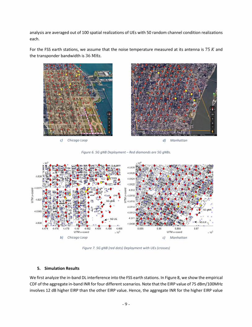
4. Simulation Setup
As we are interested in the worst-case scenario, we use a dense deployment of gNBs where ���� �200m. As shown in Figure 6, for our two FSS deployment scenarios, we deploy 108 and 106 5G gNBs,
respectively. The height of all gNBs equal to 6 m and fixed among all gNBs. We assume that the power
spectral density of every gNB is flat over the 5G network's 100MHz frequency band. We allocate a 50%
instantaneous load in the available Downlink (DL) slots. The center frequency of the 5G network is 3.75
GHz. We consider two scenarios for the maximum effective isotropic radiated power (EIRP) of the gNB
antenna: ��-��0/ � i63,75jdBm/100MHz. The transmit power values of the gNBs in different EIRP
scenarios are 43 dBm and 46 dBm, respectively. For the former case, each gNB has an antenna array of
size 8 × 4 × 2 with an element pattern bandwidth of θN./ � ϕN./ � 65∘, a down-tilt of ϕ�� ��6∘, 6�,DE/F � 30dB, and the maximum gain of individual antenna element equals to 5 dBi. This means
maximum antenna gain for this case is about 20 dBi. The latter case uses a larger antenna with an antenna
array of size 16 × 8 × 2, and the maximum gain of individual antenna element equals to 8 dBi. This
makes a maximum antenna gain of 29 dBi.
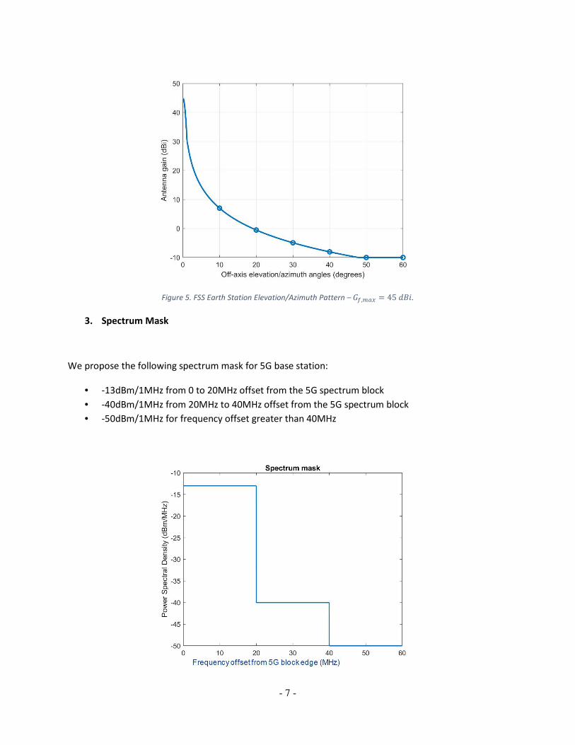
For both FSS deployment scenarios (Chicago Loop and Manhattan), we randomly deploy 500 UEs around
the map. The 80% of these UEs are indoor UEs as explained in Section 1. We show an example UE
deployment for both FSS deployment scenarios in
Figure 7. The transmit power of UEs is �� � 23dBm/100MHz. The simulation results examined in this
a) Chicago Loop b) Manhattan
- 9 -
analysis are averaged out of 100 spatial realizations of UEs with 50 random channel condition realizations
each.
For the FSS earth stations, we assume that the noise temperature measured at its antenna is 75� and
the transponder bandwidth is 36MHz.
Figure 6. 5G gNB Deployment – Red diamonds are 5G gNBs.
Figure 7. 5G gNB (red dots) Deployment with UEs (crosses)
5. Simulation Results
We first analyze the in-band DL interference into the FSS earth stations. In Figure 8, we show the empirical
CDF of the aggregate in-band INR for four different scenarios. Note that the EIRP value of 75 dBm/100MHz
involves 12 dB higher EIRP than the other EIRP value. Hence, the aggregate INR for the higher EIRP value
c) Chicago Loop d) Manhattan
b) Chicago Loop c) Manhattan

- 10 -
is always higher than the smaller EIRP value case. Note that the 5G gNBs with higher EIRP value use more
antenna elements, so their beams are narrower. Due to these narrower beams used by the higher EIRP
value scenario, the difference between the average aggregate INR is less than 12 dB. Higher EIRP also
makes association to farther UEs possible. Thus, the beam and user association schemes used in the higher
EIRP value scenario are slightly more advantageous compared to the smaller EIRP value scenario. In
addition to this observation, from the same figure, we also see that the Manhattan FSS deployment
scenario has less INR than the Chicago Loop scenario. This is mainly because of the higher building density
in the Manhattan scenario. For all four scenarios, in-band INR is quite high, without the guard band. Figure
9 shows the empirical CDF of the individual DL interference. Note that the “Noise Floor” label in Figure 9
equals to -179.85 dBm/Hz, since the noise temperature is taken as 75 K in Section 4. We can see that for
the Chicago Loop environment only 85 % of the individual in-band interference values are higher than the
Noise Floor. Similarly, this is around 92.5 % for the Manhattan environment. Therefore, the high INR is
caused by just few gNBs that are dominating the interference into the FSS earth stations.
Next, we do an analysis that shows how the interference is reduced by applying a guard band. We use
three main metrics: mean, median, and 95th percentile. 95th percentile metric represents the worst-case
scenario. In Figure 10, we see that once we apply 20 MHz guard band for the EIRP value of 63
dBm/100MHz, the worst-case aggregate DL INR drops below -10 dB. In Figure 11, as we increase the 5G
gNB EIRP to 75 dBm/100MHz, the worst-case aggregate DL for the Manhattan environment is still below
-10 dB, but it is slightly above -10 dB for the Chicago Loop environment. For all cases, the worst-case
aggregate DL INR with 20 MHz guard band is always below the -6 dB. After these observations, we plot
the empirical CDF of the aggregate out-of-band DL INR with 20 MHz guard band in Figure 12. We see the
95th percentile is around -10 dB. In terms of the coexistence of 5G and FSS, both scenarios have tolerable
DL INR. We continue our analysis with the individual out-of-band DL interference with 20 MHz guard band
in Figure 13. For all four different scenarios, we see that the individual out-of-band DL interference is
always 20 dB below the Noise Floor.
We analyze the results in a complete table with an additional comparison between 3GPP and ITU-R P.452
models. For the 5G links and the NLoS interferer-to-FSS earth station links we only use 3GPP model. We
just change the channel model used for the LoS interferer-to-FSS earth station links, because for the ITU-
R P.452 model we assume a completely flat terrain input which results with even lower path-loss than the
free space path-loss model as shown in Figure 14. Table 1 and Table 2 summarize the comparison of these
two path-loss models for the average and worst-case (95th percentile) aggregate DL INR, respectively. In
those tables, we see that increasing 5G gNB EIRP has more significant impact on the aggregate in-band DL
INR compared to the aggregate out-of-band DL INR because of the additional 3 dB coming from the 5G
gNB transmit power. For the aggregate out-of-band DL INR analysis, we use the same spectrum mask for
both EIRP values. The only difference is the 9dBi difference in the maximum 5G gNB antenna gain. As we
mentioned before, the larger antenna has narrower beams which increase the misalignment between FSS
earth station and 5G antennas and reduce the DL interference. We see that the average aggregate out-
of-band DL INR is nearly equal for the two EIRP value scenarios, whereas we see that the worst-case
aggregate DL INR is negatively affected (increased) as we increase the 5G gNB EIRP value. The main

- 11 -
observation from Table 2 is that the worst-case case aggregate DL INR is usually below -10 dB. These
results prove that 20 MHz guard band gives enough protection to FSS.
Figure 8. Aggregate In-Band DL INR – LoS interferer-to-FSS earth station links are modeled with 3GPP.
Figure 9. Individual In-Band DL Interference – LoS interferer-to-FSS earth station links are modeled with 3GPP.

- 12 -
Figure 10. Aggregate Average Downlink INR - EIRP = 63 dBm/100MHz – LoS interferer-to-FSS earth station links are modeled
with 3GPP.
Figure 11. Aggregate Average Downlink INR - EIRP = 75 dBm/100MHz – LoS interferer-to-FSS earth station links are modeled
with 3GPP.

- 13 -
Figure 12. Aggregate Out-of-Band DL INR with 20 MHz Guard Band – LoS interferer-to-FSS earth station links are modeled with
3GPP.
Figure 13. Individual Out-of-Band DL Interference with 20 MHz Guard Band – LoS interferer-to-FSS earth station links are
modeled with 3GPP.

- 14 -
Figure 14. Comparison of the 3GPP 36.873 and the ITU-R P.452 – LoS link, r� � 3.75�wx, interferer and FSS earth station
antenna height equal to 6 m.
Table 1. Average aggregate DL INR
FSS deployment scenario /
EIRP (dBm/100MHz)
Average aggregate INR (dB)
In-band Out-of-band
0 MHz guard band
Out-of-band
20 MHz guard band
3GPP
36.873
ITU-R
P.452
3GPP
36.873
ITU-R
P.452
3GPP
36.873
ITU-R
P.452
Chicago Loop, 63 34.44 35.25 -4.10 -3.30 -30.78 -29.97
Manhattan, 63 26.68 27.10 -11.86 -11.44 -38.53 -38.12
Chicago Loop, 75 37.48 38.02 -4.07 -3.52 -30.74 -30.20
Manhattan, 75 29.56 30.13 -11.99 -11.42 -38.66 -38.09
Table 2. Worst-case (95th percentile) aggregate DL INR
FSS deployment scenario /
EIRP (dBm/100MHz)
Worst-case (95th percentile) aggregate INR (dB)
In-band Out-of-band
0 MHz guard band
Out-of-band
20 MHz guard band
3GPP
36.873
ITU-R
P.452
3GPP
36.873
ITU-R
P.452
3GPP
36.873
ITU-R
P.452
Chicago Loop, 63 53.73 54.92 15.18 16.38 -11.49 -10.29
Manhattan, 63 51.67 52.00 13.12 13.46 -13.55 -13.22
Chicago Loop, 75 59.62 60.31 18.07 18.77 -8.60 -7.90
Manhattan, 75 56.33 55.92 14.79 14.37 -11.88 -12.30

- 15 -
6. Conclusions
Our study concludes that co-channel deployment of 5G and FSS ESs could incur significant interference
to FSS ESs when in close proximity to each other. Since co-channel operation of 5G and FSS fixed earth
stations in close proximity could be problematic, we studied the case where the two systems are not
using the same spectrum blocks. Under our assumptions and deployment scenarios, a guard band of 20
MHz between FSS and 5G would provide sufficient protection to the FSS earth stations when assuming
the 5G spectrum mask discussed above.
Based on the initial coexistence considerations, Nokia urges the Commission to clear the band of FSS
ESs, especially when in close proximity of 5G systems, starting at the 3700MHz edge, to allow 5G
systems to thrive in the band.
Nokia also believes that the 20 MHz guard band would be enough for a filter on the earth station
receiver to provide the necessary rejection performance that would prevent 5G transmission from
saturating the Low Noise Block converter (LNB) of the earth stations. Such an external filter should be
tunable across 3700-4200 MHz band. We do not foresee that this would translate into additional
requirements on the 5G system. The FSS providers can work with manufacturers to define the filter
characteristics such as rejection, roll-off, and insertion loss. Proceeds from an auction or market-based
approach could be used to pay for such filters.
7. References
[1] FCC International Bureau Application Filing and Reporting System. [Online]. Available: http://licensing.fcc.gov/myibfs/
[2] G. Hattab, P. Moorut, E. Visotsky, M. Cudak and A. Ghosh, "Interference Analysis of the Coexistence of 5G Cellular
Networks with Satellite Earth Stations in 3.7-4.2GHz," 2018 IEEE International Conference on Communications Workshops (ICC
Workshops), Kansas City, MO, 2018, pp. 1-6.
[3] Intelsat & SES, "C-Band / 5G Coexistence", FCC Debrief, 4/19/2018.
[4] 3GPP, “Study on scenarios and requirements for next generation access technologies,” 3rd Generation Partnership
Project (3GPP), Tech. Rep., 2017.
[5] 3GPP, “Study on 3d channel model for LTE,” 3rd Generation Partnership Project (3GPP), TR 36.873, 2017.
[6] ITU-R, “Receiving reference earth station antenna pattern for earth stations in FSS in the frequency range from 2 to
31 ghz coordinated after 1993,” Tech. Rep. S.465-6, 2016.
[7] ITU-R, “Prediction procedure for the evaluation of interference between stations on the surface of the Earth at
frequencies above about 0.1 GHz,” Tech. Rep. P.452-16, 2015.
[8] B. A. Coalition, “Petition for rulemaking to amend and modernize parts 25 and 101 of the commission’s rules to
authorize and facilitate the deployment of licensed point-to-multipoint fixed wireless broadband service in the 3700 – 4200
mhz band,” Tech. Rep., 2017.