Embed Size (px)
Citation preview

BEFORE YOU BEGIN INSTALLATION:
• Check all parts with the those listed above before beginning installation.
• If any parts are missing, contact IHC Suspension at 956-424-6901 and a replacement part will
be sent to you immediately.
• Throughly read all instructions from start to finish before beginning the installation.
• If these instructions are not properly followed, then severe frame, driveline, and/or suspension
damage may occur.
• Check your local city and state laws prior to the installation of this system for legality.
• Do not install if not legal in your area.
• Prior to the installation of this suspension system, perform a front-end alignment and record. Do
not install this system if the vehicle alignment is not within factory specifications.
• Check for frame and suspension damage prior to installation.
• The installation of this suspension system should be performed by two professional mechanics.
• Do not combine this suspension system with any other drop device or parts.
• MAKE SURE TO HAVE ALL PARTS BEFORE STARTING INSTALLATION.
WWW.IHCSUSPENSION.COM EMAIL: [email protected] (956) 424-6901
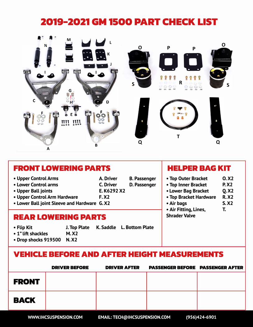
2019-2021 GM 1500 PART CHECK LIST
,. ,.
A
M
nn nn •••• ••••
� �L
••
--J
•'•
B
FRONT LOWERING PARTS
0
Q
A. Driver B. PassengerC. Driver D. Passenger
E. K6292 X2
F.X2
• Upper Control Arms
• Lower Control arms
• Upper Ball joints
• Upper Control Arm Hardware
• Lower Ball joint Sleeve and Hardware G. X2
REAR LOWERING PARTS
• Flip Kit J. Top Plate K. Saddle L. Bottom Plate
• 1" lift shackles M. X2
• Drop shocks 919 500 N. X2
p p
DD _, ..,
R
T
-...., � ..._, • >
0
Q
HELPER BAG KIT
0. X2P. X2
Q. X2
• Air bags S. X2
T.
• Top Outer Bracket
• Top Inner Bracket
• Lower Bag Bracket
• Top Bracket Hardware R. X2
• Air Fitting, Lines,
Shrader Valve
VEHICLE BEFORE AND AFTER HEIGHT MEASUREMENTS
FRONT
BACK
DRIVER BEFORE DRIVER AFTER PASSENGER BEFORE PASSENGER AFTER
WWW.IHCSUSPENSION.COM EMAIL: [email protected] (956)424-6901
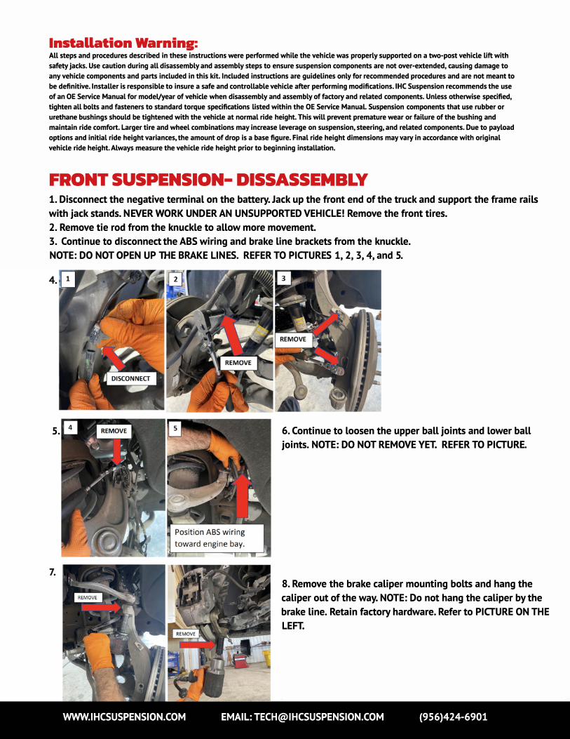
Installation Warning: All steps and procedures described in these instructions were performed while the vehicle was properly supported on a two-post vehicle lift with
safety jacks. Use caution during all disassembly and assembly steps to ensure suspension components are not over-extended, causing damage to
any vehicle components and parts included in this kit. Included instructions are guidelines only for recommended procedures and are not meant to
be definitive. Installer is responsible to insure a safe and controllable vehicle after performing modifications. lHC Suspension recommends the use
of an OE Service Manual for model/year of vehicle when disassembly and assembly of factory and related components. Unless otherwise specified,
tighten all bolts and fasteners to standard torque specifications listed within the OE Service Manual Suspension components that use rubber or
urethane bushings should be tightened with the vehicle at normal ride height. This will prevent premature wear or failure of the bushing and
maintain ride comfort. Larger tire and wheel combinations may increase leverage on suspension, steering, and related components. Due to payload
options and initial ride height variances, the amount of drop is a base figure. Final ride height dimensions may vary in accordance with original
vehicle ride height. Always measure the vehicle ride height prior to beginning installation.
FRONT SUSPENSION- DISSASSEMBLY
1. Disconnect the negative terminal on the battery. Jack up the front end of the truck and support the frame rails
with jack stands. NEVER WORK UNDER AN UNSUPPORTED VEHICLE! Remove the front tires.
2. Remove tie rod from the knuckle to allow more movement.
3. Continue to disconnect the ABS wiring and brake line brackets from the knuckle.
NOTE: DO NOT OPEN UP THE BRAKE LINES. REFER TO PICTURES 1, 2, 3, 4, and 5.
6. Continue to loosen the upper ball joints and lower ball
joints. NOTE: DO NOT REMOVE YET. REFER TO PICTURE.
8. Remove the brake caliper mounting bolts and hang the
caliper out of the way. NOTE: Do not hang the caliper by the
brake line. Retain factory hardware. Refer to PICTURE ON THE
LEFT.
9. Properly hang caliper to prevent
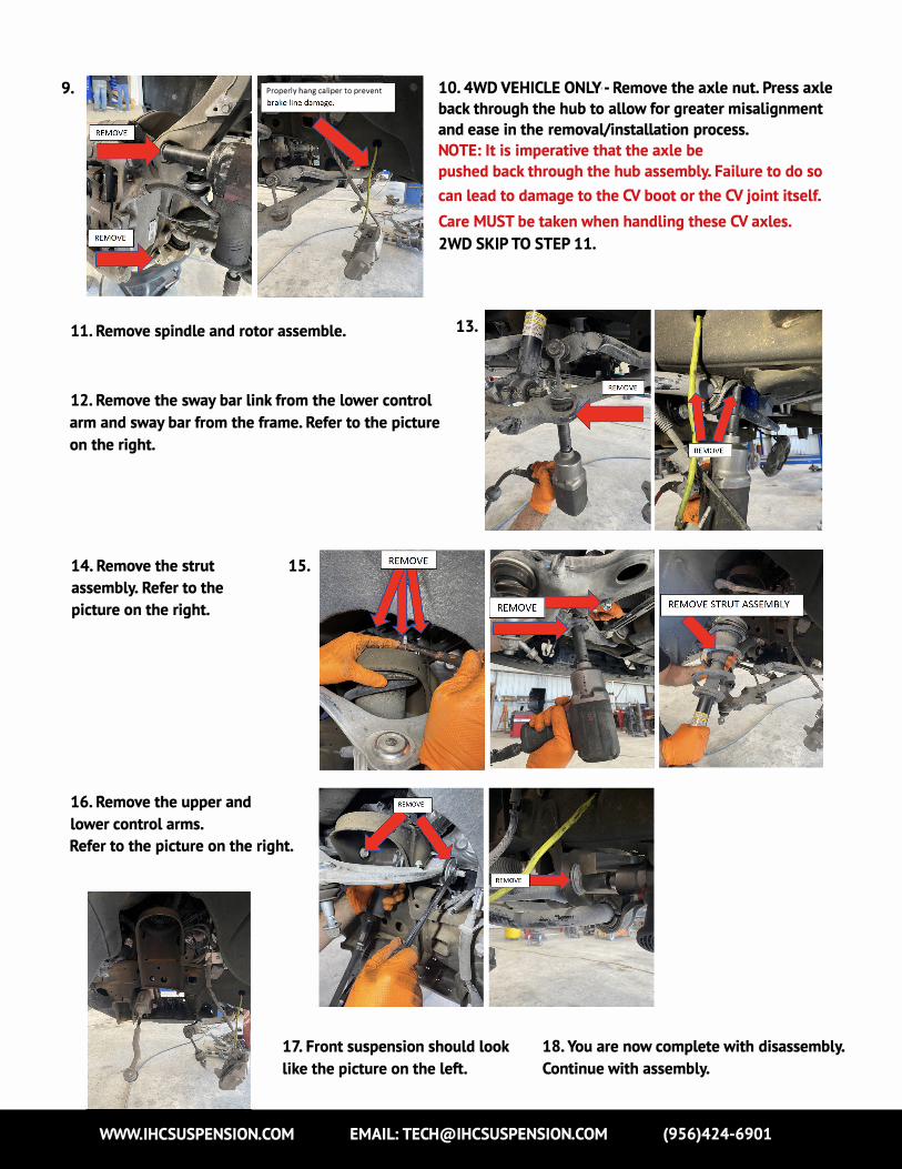
11. Remove spindle and rotor assemble.
12. Remove the sway bar link from the lower control
arm and sway bar from the frame. Refer to the picture
on the right.
15. 14. Remove the strut
assembly. Refer to the
picture on the right.
16. Remove the upper and
lower control arms.
Refer to the picture on the right.
10. 4WD VEHICLE ONLY - Remove the axle nut. Press axle
back through the hub to allow for greater misalignment
and ease in the removaVinstallation process.
NOTE: It is imperative that the axle be
pushed back through the hub assembly. Failure to do so
can lead to damage to the CV boot or the CV joint itself.
Care MUST be taken when handling these CV axles.
2WD SKIP TO STEP 11.
13.
17. Front suspension should look
like the picture on the left.
18. You are now complete with disassembly.
Continue with assembly.
WWW.IHCSUSPENSION.COM EMAIL: [email protected] (956)424-6901
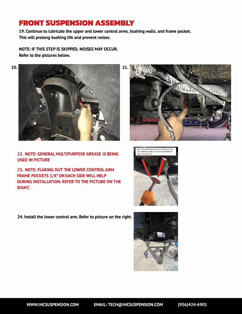
20.
FRONT SUSPENSION ASSEMBLY
19. Continue to lubricate the upper and lower control arms, bushing walls, and frame pocket.
This will prolong bushing life and prevent noises.
NOTE: IF THIS STEP IS SKIPPED, NOISES MAY OCCUR.
Refer to the pictures below.
21.
22. NOTE: GENERAL MULTIPURPOSE GREASE IS BEING
USED IN PICTURE
23. NOTE: FLARING OUT THE LOWER CONTROL ARM
FRAME POCKETS 1/8" ON EACH SIDE WILL HELP
DURING INSTALLATION. REFER TO THE PICTURE ON THE
RIGHT.
24. Install the lower control arm. Refer to picture on the right.
NOTE: RECOMMENDATION ON FLARING IS ONLY
WWW.IHCSUSPENSION.COM EMAIL: [email protected] (956)424-6901

25. Install the OEM bolts. Remove and discard the alignment plastic from OEM alignment CAM. Install the
lHC Alignment LOCK over the OEM alignment CAM ON THE NUT SIDE. DO NOT TIGHTEN BOLTS AT THIS
TIME.
NOTE: IT'S RECOMMENDED TO SET
THE ALIGNMENT IN THE MIDDLE
MARK. THIS WILL ALLOW FOR
EASIER COMPUTER ALIGNMENT.
REFER TO PICTURES ON THE RIGHT.
26. Install the upper ball joint onto the IHC upper control arm with the
hardware provided. TORQUE 18FT-LBS. Refer to the picture on the left.
27. Install the lHC upper control arm. NOTE: Install the 9/16
smaller washer towards the head of the bolt and the 9/16
bigger washer toward the nut side. Refer to the pieture
below.
TORQUE TO 110 FT-LBS
28. Install the strut assembly. Torque
the upper and lower strut bolts to 35
FT-LBS.
Refer to the picture on the
left.
WWW.IHCSUSPENSION.COM EMAIL: [email protected] (956)424-6901
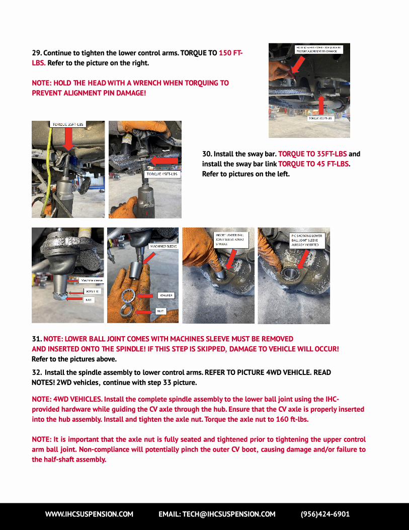
29. Continue to tighten the lower control arms. TORQUE TO 150 FT-
LBS. Refer to the picture on the right.
NOTE: HOLD THE HEAD WITH A WRENCH WHEN TORQUING TO
PREVENT ALIGNMENT PIN DAMAGE!
30. Install the sway bar. TORQUE TO 35FT-LBS and
install the sway bar link TORQUE TO 45 FT-LBS.
Refer to pictures on the left.
31. NOTE: LOWER BALL JOINT COMES WITH MACHINES SLEEVE MUST BE REMOVED
AND INSERTED ONTO THE SPINDLE! IF THIS STEP IS SKIPPED, DAMAGE TO VEHICLE WILL OCCUR!
Refer to the pictures above.
32. Install the spindle assembly to lower control arms. REFER TO PICTURE 4WD VEHICLE. READ
NOTES! 2WD vehicles, continue with step 33 picture.
NOTE: 4WD VEHICLES. Install the complete spindle assembly to the lower ball joint using the IHC-
provided hardware while guiding the CV axle through the hub. Ensure that the CV axle is properly inserted
into the hub assembly. Install and tighten the axle nut. Torque the axle nut to 160 ft-lbs.
NOTE: It is important that the axle nut is fully seated and tightened prior to tightening the upper control
arm ball joint. Non-compliance will potentially pinch the outer CV boot, causing damage and/or failure to
the half-shaft assembly.
WWW.IHCSUSPENSION.COM EMAIL: [email protected] (956)424-6901

33. You will need to raise the lower control furthest away
from the pivot point to be able to bolt up the upper ball
joint to the spindle. DO NOT RAISE FROM THE LOWER
CONTROL ARM POCKET! With the floor jack raised, lower
the control arm a couple of inches to install the upper
ball joint onto the spindle. Refer to the picture on the
right.
NOTE: MAKE SURE YOU DO NOT RAISE VEHICLE OFF
HOIST. DAMAGE OR SERIOUS INJURY MAY OCCUR!
34. ADD red loc-tite provided in the
kit to the lower ball joint thread
and nut. Refer to pieture. Install the
locking washer and TORQUE TO 120
FT-LBS
35. Install the upper ball joint castle
nut and TORQUE TO 65 FT-LBS. Add
the cotter pin. Refer to the picture
on the right.
36. Install the brake caliper
assembly. TORQUE TO 100FT-LBS.
Refer to the picture on the right.
NOTE: RED LOC-TITE MUST BE
ADDED. IF THIS STEP IS
SKIPPED, DAMAGE OR SERIOUS
INJURY MAY OCCUR.
WWW.IHCSUSPENSION.COM EMAIL: [email protected] (956)424-6901

37. Install all ABS brackets and TORQUE TO 80 INCH-LBS.
38. Install the ABS SENSOR onto the OEM spindle. TORQUE TO 80
INCH-LBS
38. Bolt down the ABS wiring to UPPER
control. Refer to the picture on the right.
39. With everything tightened and torqued to the
specifications, install the front tires and lower the
vehicle. With the steering wheel centered, turn
the tie rod ends until the tires are straight.
40. NOTE: If the steering wheel is not centered
properly, the ABS/traction control lights may
activate. Turn the wheels from lock to lock and
make sure the brake lines and ABS routing clears
all suspension components adequately.
41. Reposition if necessary.
42. Using the appropriate tool, grease the upper
ball and lower ball joint just until the boot starts
to expand. Do not overgrease. Overgrease can
cause premature wear. Refer to the picture on the
right.
43. You are now complete with front installation.
WWW.IHCSUSPENSION.COM EMAIL: [email protected] (956)424-6901


![IHC PPT Ancillary Productsmy1hr-public.s3.amazonaws.com/documents/enroll/IHC PPT Ancillary Products[3].pdfAncillary Products From The IHC Group. The IHC Group Corporate Overview Ø](https://img.pdfslide.net/doc/110x75/5e38c9b5e1bb9a3e4e5b3bd8/ihc-ppt-ancillary-productsmy1hr-publics3-ppt-ancillary-products3pdf-ancillary.jpg)