Embed Size (px)
Citation preview
Behavior of overlapping Cold Formed Z-Beams
124 www.erpublication.org
Abstract— Z-section is one of the most common cold-formed
purlins. Its lapping ability provides continuity, and double
thickness at the support regions. Four different types of systems
may be found in modern roofs; single span, double span,
multi-span with sleeves and multi-span with overlaps is the
most popular. Four verification cases: simple and overhanging
beams are conducted, using FEM to investigate the structural
behaviour of lapped connections over the internal supports in
multi-span systems with overlap. Results are compared with
code and previous experimental work and good agreement is
achieved.
In this study, The moment resistance of overhanging
Z-purlin with constant thickness (1.5 mm) ,different heights
(142,172,202 and 232 mm) and overlap lengths (0.1L to
0.5L) ,where L is the back span length are investigated under
combined bending and shear using ANSYS14.00. For each lap
length and height, models were also conducted with and without
straps with either restrained compression flanges or not.
Index Terms— Cold Formed ,overhanging beams ,Z-beams
,Finite Element.
I. INTRODUCTION
Cold-formed steel sections are lightweight building
materials with high strength to self-weight ratios. They are
suitable for building construction owing to their versatility in
applications, and ease of fabrication and installation. In
general, both cold-formed steel C sections [1-3] and Z
sections [4-8] are widely used in building construction. The
section depths typically range from 100 to 350 mm while the
section thicknesses typically range from 1.2 to 3.0 mm
[9-11]. Z-sections are recommended for the use as purlins for
a variety of reasons, the main one is that their principal axis
often coincides with the roof pitch thus enabling the designer
to take full advantage of the strength of this section. The
second advantage is that they offer easier fixing, since the top
flange does not interfere with the fixing equipment. The
purlins are connected to the rafter using angles which provide
some torsional restraint to the section otherwise it may twist.
The third one is that, Z section is better than C section
because it can easily lap the Z section at support with the Z
section face to face but incase lapping the C section they will
be back to back. This require the seam lines of the roof metal
deck to be shifted between panel which is impossible to
achieve[12].
Four different types of purlin systems may be found in
modern roofs with different degrees of continuity: (i) single
span, (ii) double span, (iii) multi-span with sleeves, and (iv)
multi-span with overlaps[6]. The load carrying capacities of
these purlin systems depend on many factors, such as steel
Manuscript received November 11, 2014. Sally Hosny Taha, Steel Structural department, Suez Canal university/
Faculty of Engineering/ Ismailia, Egypt, +201221583048.
Dr.Rimon Aziz Samaan, Steel Structural department, Ain Shams university / Faculty of Engineering / Cairo, Egypt, +201001419553.
Prof.Dr.Nahla K. Hassan, Steel Structural department, Ain Shams
university / Faculty of Engineering / Cairo, Egypt, +201222373098.
grades, section shapes and sizes of purlin members, restraints
provided by attached roof cladding and intermediate bracing
members, and connection configurations at purlin–rafter
supports. In practice, multi-span purlin systems with overlaps
are the most popular owing to their high structural efficiency
and simple installation of purlin–rafter connections. The
general member arrangement of multi-span purlin systems
with overlaps can be easily modeled by two cases as a simple
beam [5-7]or as an overhanging beam [8].
The main objectives of this paper is to develop Finite
element models using Ansys14 [13] to simulate the
experimental behavior of lapped connections between
cold-formed steel Z sections by verifying the results obtained
by the proposed finite element model against experimental
investigation performed by others [5, 7, 8]. A comprehensive
set of previous experimental work is provided to illustrate the
various capabilities of the nonlinear finite element proposed
model. These cases are selected to cover a wide range of
applications both in geometry and loading of the tested
specimens.
In the parametric study, The moment resistance of
overhanging Z-purlin with constant thickness (1.5 mm)
,different heights (142,172,202 and 232 mm) and overlap
lengths (0.1L to 0.5L ,where L is the back span length) are
investigated under combined bending and shear using
ANSYS14.00 [13]. For each lap length and height, models
were also conducted with and without straps with either
restrained compression flanges or not.
II. VERIFICATION OF EXPERIMENTAL AND FINITE ELEMENT
MODEL
The verification cases consists of two parts; experimental
work and codes. Three main different experimental studies
that were conducted by three different researchers; Cao Hung
Pham 2014[5], Ahmad A. Ghosn 1995 [7], Ain Shams and
Zamil 2014 [8] were verified to evaluate the performance of
the FE model for different specimens. The second part,
proposed models were compared with the flexural strength
code equations of AISI 2007[14] for beams subjected to
combined bending and shear,. The accurate results of FE
analysis can be utilized to predict the ultimate loads of
cold-formed lapped Z-section purlin subjected to combined
bending and shear.
A. F.E. Model Geometry
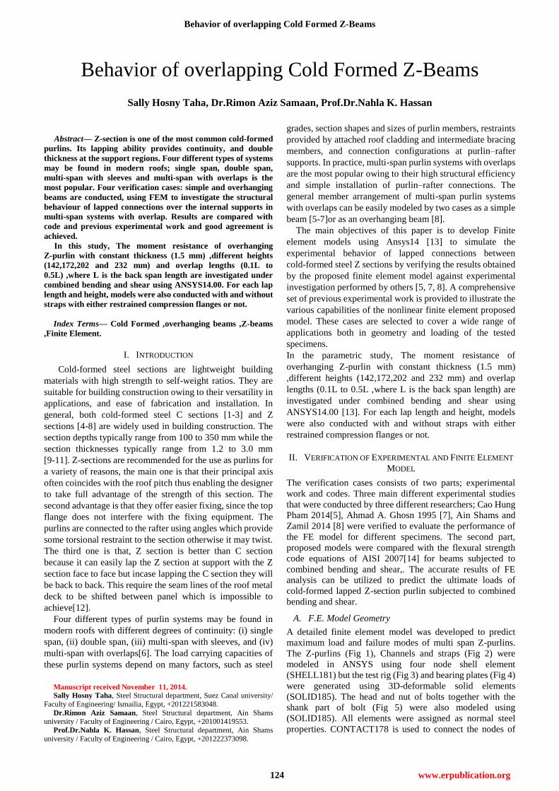
A detailed finite element model was developed to predict
maximum load and failure modes of multi span Z-purlins.
The Z-purlins (Fig 1), Channels and straps (Fig 2) were
modeled in ANSYS using four node shell element
(SHELL181) but the test rig (Fig 3) and bearing plates (Fig 4)
were generated using 3D-deformable solid elements
(SOLID185). The head and nut of bolts together with the
shank part of bolt (Fig 5) were also modeled using
(SOLID185). All elements were assigned as normal steel
properties. CONTACT178 is used to connect the nodes of
Behavior of overlapping Cold Formed Z-Beams
Sally Hosny Taha, Dr.Rimon Aziz Samaan, Prof.Dr.Nahla K. Hassan
International Journal of Engineering and Technical Research (IJETR)
ISSN: 2321-0869, Volume-2, Issue-11, November 2014
125 www.erpublication.org
i)the two overlapped Z beams as shown in Fig 6. ii)Straps and
flanges of Purlins iii)channel and web of Z section. The 10
mm element mesh was selected that gave high accuracy
within a reasonable time. For modeling of boundary
conditions, two single points (A,B) were modeled in the
center of two bearing plates of thickness 20mm (Fig 7), one
hinged support and the other is roller as shown in Fig 8.
Because of the symmetric cross section, a symmetry
boundary condition was also applied on a plane of nodes
according YZ plane for the whole model, Fig 3,8. A
concentrated load was applied over a 30mm head plate Fig 3.
a non-linear analysis that considered material and geometric
non-linearity was performed using the arc-length method.
The maximum and minimum multiplier of the reference
arc-length radius was 1 and 0.0001, respectively.
B.
Fig 6.contact node to node
Fig 1.Shell Element of cold formed Z-section
Fig 2.Shell Element of stiffeners
a) Channel b) Straps
Fig 3.Loads on the Finite Element Model.
Load
Symm. B.C.
Loading Plate
Fig 4.Solid Element of bearing plate
Fig 5.Solid Element of bolts
Span
A B
Bearing plate
t=20mm
Fig 7.Plan of Bearing plate.
Bearing Plate
Fig 8.One hinged support on the center of bearing
plate.
Behavior of overlapping Cold Formed Z-Beams
126 www.erpublication.org
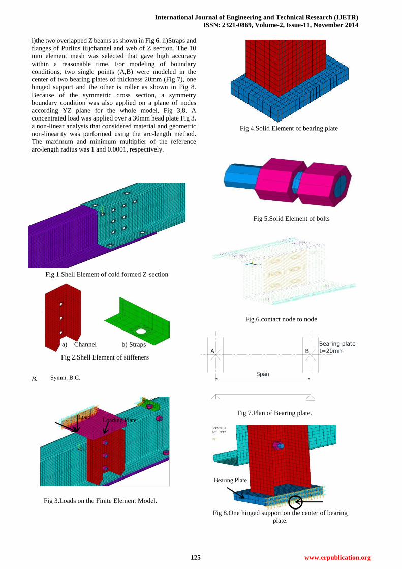
Fig10.Test with straps
Fig 9.Test without Straps
b)With Straps a)Without Straps
Fig11.Finite Element Model.
Fig 12. Load and vertical displacement relations of
MVw-Z20015-300 mm
F.E. Validation of Experimental Results
Case I; Cao Pham (2014) [5]
When you submit your final version, after your paper has
been accepted, prepare it in two-column format, including
figures and tables.
The experimental program comprised a total of four tests.
All tests were performed in the 2000 kN capacity for a
continuous lapped Z purlin connection based on the
simplified analysis as a simple beam.
The Z-section purlins were tested in pairs with top flanges
facing inwards and with a gap between them to ensure that
the inside assembly was possible. Two tests were conducted
with six 25 × 25 × 5EA straps which were uniformly and
symmetrically connected by self-tapping screws on the top
flanges as shown in Fig 10. The purpose of these two straps is
to prevent distortion of the top flanges under compression
caused by bending moment. It is believed that sheeting screw
fastened to the top flanges will have a similar effect to the
straps in the tests with straps. other tests were conducted
without Straps Fig 9.
using same elements as previously mentioned, the F.E.
mesh and boundary conditions as shown in Fig 11. The
comparison between the experimental program results and
the proposed numerical model results are summarized in
Table 1.
Table 1.Comparsion between finite element model and
experimental results
It is evident for Table 1, that the finite element model
results are in good agreement with the experimental results:
ratio within a maximum deviation of 8 %.
As shown in Fig 12 and Fig 13, the results of the F.E.
models and the experimental work were in good agreement.
The load dropped more suddenly in Specimen with straps
(Fig 13) than that without the straps as shown in Fig 12 due to
the local buckling mode in the flange.
Good agreement in various failure modes was achieved for
the F.E. models with the experimental work. For beams
without Straps Fig 14, the top flange of the lower Z-section
buckled and was pulled in and down. Simultaneously, the top
flange of the upper Z-section was twisted and lifted due to the
discontinuity of the connection in bending. But with Straps
Fig 15, local buckling occurred in the top flange of the upper
Z-section. No distortion at the cross-section was observed
due to the straps which may significantly increase the
capacity and enhance the continuity of the lapped connection.
Specimen
a
(m
m)
Experimenta
l FEM
Acc
(%) Failure load
(kN)
Model
results
(kN)
MVw-Z20015 100 34.31 36.47 -6.3
MVw-Z20015 300 48.041 46.42 3.4
MVs-Z20015 100 51.89 55.5 -7.0
MVs-Z20015 300 68.00 62.4 8.2
Fig 13.Load and vertical displacement relations of
MVs-Z20015-300 mm
International Journal of Engineering and Technical Research (IJETR)
ISSN: 2321-0869, Volume-2, Issue-11, November 2014
127 www.erpublication.org
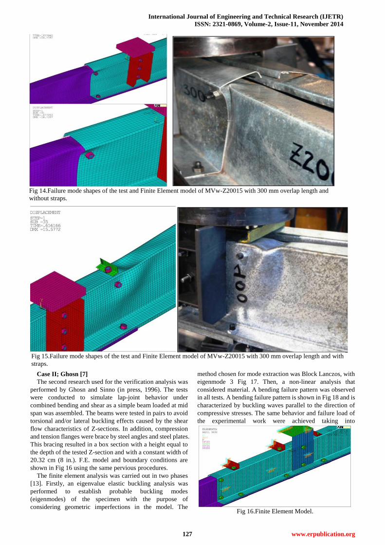
Fig 15.Failure mode shapes of the test and Finite Element model of MVw-Z20015 with 300 mm overlap length and with
straps.
Case II; Ghosn [7]
The second research used for the verification analysis was
performed by Ghosn and Sinno (in press, 1996). The tests
were conducted to simulate lap-joint behavior under
combined bending and shear as a simple beam loaded at mid
span was assembled. The beams were tested in pairs to avoid
torsional and/or lateral buckling effects caused by the shear
flow characteristics of Z-sections. In addition, compression
and tension flanges were brace by steel angles and steel plates.
This bracing resulted in a box section with a height equal to
the depth of the tested Z-section and with a constant width of
20.32 cm (8 in.). F.E. model and boundary conditions are
shown in Fig 16 using the same pervious procedures.
The finite element analysis was carried out in two phases
[13]. Firstly, an eigenvalue elastic buckling analysis was
performed to establish probable buckling modes
(eigenmodes) of the specimen with the purpose of
considering geometric imperfections in the model. The
method chosen for mode extraction was Block Lanczos, with
eigenmode 3 Fig 17. Then, a non-linear analysis that
considered material. A bending failure pattern was observed
in all tests. A bending failure pattern is shown in Fig 18 and is
characterized by buckling waves parallel to the direction of
compressive stresses. The same behavior and failure load of
the experimental work were achieved taking into
Fig 14.Failure mode shapes of the test and Finite Element model of MVw-Z20015 with 300 mm overlap length and
without straps.
Fig 16.Finite Element Model.
Behavior of overlapping Cold Formed Z-Beams
128 www.erpublication.org
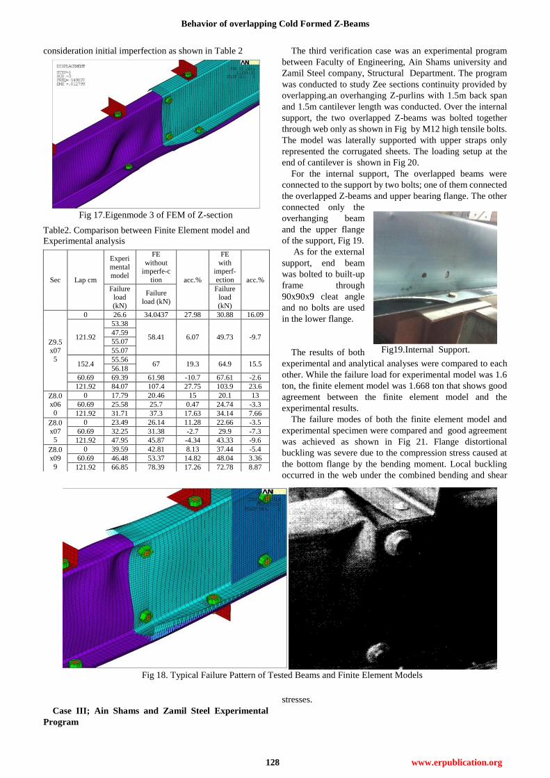
Fig 18. Typical Failure Pattern of Tested Beams and Finite Element Models
Fig19.Internal Support.
consideration initial imperfection as shown in Table 2
Table2. Comparison between Finite Element model and
Experimental analysis
Case III; Ain Shams and Zamil Steel Experimental
Program
The third verification case was an experimental program
between Faculty of Engineering, Ain Shams university and
Zamil Steel company, Structural Department. The program
was conducted to study Zee sections continuity provided by
overlapping.an overhanging Z-purlins with 1.5m back span
and 1.5m cantilever length was conducted. Over the internal
support, the two overlapped Z-beams was bolted together
through web only as shown in Fig by M12 high tensile bolts.
The model was laterally supported with upper straps only
represented the corrugated sheets. The loading setup at the
end of cantilever is shown in Fig 20.
For the internal support, The overlapped beams were
connected to the support by two bolts; one of them connected
the overlapped Z-beams and upper bearing flange. The other
connected only the
overhanging beam
and the upper flange
of the support, Fig 19.
As for the external
support, end beam
was bolted to built-up
frame through
90x90x9 cleat angle
and no bolts are used
in the lower flange.
The results of both
experimental and analytical analyses were compared to each
other. While the failure load for experimental model was 1.6
ton, the finite element model was 1.668 ton that shows good
agreement between the finite element model and the
experimental results.
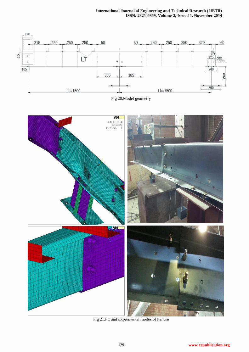
The failure modes of both the finite element model and
experimental specimen were compared and good agreement
was achieved as shown in Fig 21. Flange distortional
buckling was severe due to the compression stress caused at
the bottom flange by the bending moment. Local buckling
occurred in the web under the combined bending and shear
stresses.
Sec Lap cm
Experi
mental
model
FE
without imperfe-c
tion acc.%
FE
with imperf-
ection acc.%
Failure load
(kN)
Failure
load (kN)
Failure load
(kN)
Z9.5x07
5
0 26.6 34.0437 27.98 30.88 16.09
121.92
53.38
58.41 6.07 49.73 -9.7 47.59
55.07
55.07
152.4 55.56
67 19.3 64.9 15.5 56.18
60.69 69.39 61.98 -10.7 67.61 -2.6
121.92 84.07 107.4 27.75 103.9 23.6
Z8.0
x06
0
0 17.79 20.46 15 20.1 13
60.69 25.58 25.7 0.47 24.74 -3.3
121.92 31.71 37.3 17.63 34.14 7.66
Z8.0
x075
0 23.49 26.14 11.28 22.66 -3.5
60.69 32.25 31.38 -2.7 29.9 -7.3
121.92 47.95 45.87 -4.34 43.33 -9.6
Z8.0
x09
9
0 39.59 42.81 8.13 37.44 -5.4
60.69 46.48 53.37 14.82 48.04 3.36
121.92 66.85 78.39 17.26 72.78 8.87
Fig 17.Eigenmode 3 of FEM of Z-section
International Journal of Engineering and Technical Research (IJETR)
ISSN: 2321-0869, Volume-2, Issue-11, November 2014
129 www.erpublication.org
Lc=1500 Lb=1500
385385
50 250
65
250 250 320 60
105
125
200
268
350
50250250250315
170
20
CBOL 90x9LT
Fig 21.FE and Expermental modes of Failure
Fig 20.Model geometry
Behavior of overlapping Cold Formed Z-Beams
130 www.erpublication.org
h
bB
bT
Lt
t
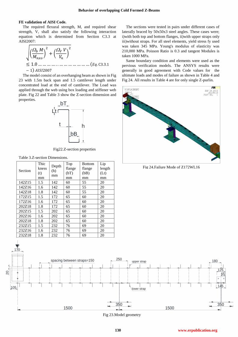
Fig22.Z-section properties
FE validation of AISI Code.
The required flexural strength, M, and required shear
strength, V, shall also satisfy the following interaction
equation which is determined from Section C3.3 at
AISI2007:
√(
)
(
)
( )
The model consist of an overhanging beam as shown in Fig
23 with 1.5m back span and 1.5 cantilever length under
concentrated load at the end of cantilever. The Load was
applied through the web using box loading and stiffener web
plate. Fig 22 and Table 3 show the Z-section dimension and
properties.
Table 3.Z-section Dimensions.
The sections were tested in pairs under different cases of
laterally braced by 50x50x3 steel angles. These cases were;
i)with both top and bottom flanges, ii)with upper straps only
iii)without straps. For all steel elements, yield stress fy used
was taken 345 MPa. Young's modulus of elasticity was
210,000 MPa. Poisson Ratio is 0.3 and tangent Modules is
taken 1000 MPa.
Same boundary condition and elements were used as the
pervious verification models. The ANSYS results were
generally in good agreement with Code values for the
ultimate loads and modes of failure as shown in Table 4 and
Fig 24. All results in Table 4 are for only single Z-purlin.
Section
Thic
kness
(t)
mm
Depth
(h)
mm
Top
flange
(bT)
mm
Bottom
flange
(bB)
mm
Lip
length
(Lt)
mm
142Z15 1.5 142 60 55 20
142Z16 1.6 142 60 55 20
142Z18 1.8 142 60 55 20
172Z15 1.5 172 65 60 20
172Z16 1.6 172 65 60 20
202Z18 1.8 172 65 60 20
202Z15 1.5 202 65 60 20
202Z16 1.6 202 65 60 20
202Z18 1.8 202 65 60 20
232Z15 1.5 232 76 69 20
232Z16 1.6 232 76 69 20
232Z18 1.8 232 76 69 20
1500 1500
65
105
125
145
350
170
20
lower strap
upper strap250
180
350
spacing between straps=150
Fig 24.Failure Mode of Z172WL16
Fig 23.Model geometry
International Journal of Engineering and Technical Research (IJETR)
ISSN: 2321-0869, Volume-2, Issue-11, November 2014
131 www.erpublication.org
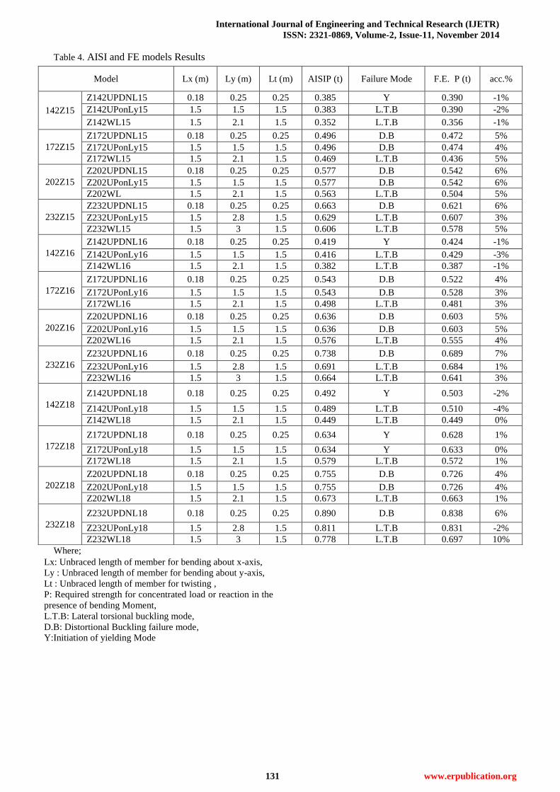
Table 4. AISI and FE models Results
Where;
Lx: Unbraced length of member for bending about x-axis,
Ly : Unbraced length of member for bending about y-axis,
Lt : Unbraced length of member for twisting ,
P: Required strength for concentrated load or reaction in the
presence of bending Moment,
L.T.B: Lateral torsional buckling mode,
D.B: Distortional Buckling failure mode,
Y:Initiation of yielding Mode
Model Lx (m) Ly (m) Lt (m) AISIP (t) Failure Mode F.E. P (t) acc.%
142Z15
Z142UPDNL15 0.18 0.25 0.25 0.385 Y 0.390 -1%
Z142UPonLy15 1.5 1.5 1.5 0.383 L.T.B 0.390 -2%
Z142WL15 1.5 2.1 1.5 0.352 L.T.B 0.356 -1%
172Z15
Z172UPDNL15 0.18 0.25 0.25 0.496 D.B 0.472 5%
Z172UPonLy15 1.5 1.5 1.5 0.496 D.B 0.474 4%
Z172WL15 1.5 2.1 1.5 0.469 L.T.B 0.436 5%
202Z15
Z202UPDNL15 0.18 0.25 0.25 0.577 D.B 0.542 6%
Z202UPonLy15 1.5 1.5 1.5 0.577 D.B 0.542 6%
Z202WL 1.5 2.1 1.5 0.563 L.T.B 0.504 5%
232Z15
Z232UPDNL15 0.18 0.25 0.25 0.663 D.B 0.621 6%
Z232UPonLy15 1.5 2.8 1.5 0.629 L.T.B 0.607 3%
Z232WL15 1.5 3 1.5 0.606 L.T.B 0.578 5%
142Z16
Z142UPDNL16 0.18 0.25 0.25 0.419 Y 0.424 -1%
Z142UPonLy16 1.5 1.5 1.5 0.416 L.T.B 0.429 -3%
Z142WL16 1.5 2.1 1.5 0.382 L.T.B 0.387 -1%
172Z16
Z172UPDNL16 0.18 0.25 0.25 0.543 D.B 0.522 4%
Z172UPonLy16 1.5 1.5 1.5 0.543 D.B 0.528 3%
Z172WL16 1.5 2.1 1.5 0.498 L.T.B 0.481 3%
202Z16
Z202UPDNL16 0.18 0.25 0.25 0.636 D.B 0.603 5%
Z202UPonLy16 1.5 1.5 1.5 0.636 D.B 0.603 5%
Z202WL16 1.5 2.1 1.5 0.576 L.T.B 0.555 4%
232Z16
Z232UPDNL16 0.18 0.25 0.25 0.738 D.B 0.689 7%
Z232UPonLy16 1.5 2.8 1.5 0.691 L.T.B 0.684 1%
Z232WL16 1.5 3 1.5 0.664 L.T.B 0.641 3%
142Z18
Z142UPDNL18 0.18 0.25 0.25 0.492 Y 0.503 -2%
Z142UPonLy18 1.5 1.5 1.5 0.489 L.T.B 0.510 -4%
Z142WL18 1.5 2.1 1.5 0.449 L.T.B 0.449 0%
172Z18
Z172UPDNL18 0.18 0.25 0.25 0.634 Y 0.628 1%
Z172UPonLy18 1.5 1.5 1.5 0.634 Y 0.633 0%
Z172WL18 1.5 2.1 1.5 0.579 L.T.B 0.572 1%
202Z18
Z202UPDNL18 0.18 0.25 0.25 0.755 D.B 0.726 4%
Z202UPonLy18 1.5 1.5 1.5 0.755 D.B 0.726 4%
Z202WL18 1.5 2.1 1.5 0.673 L.T.B 0.663 1%
232Z18
Z232UPDNL18 0.18 0.25 0.25 0.890 D.B 0.838 6%
Z232UPonLy18 1.5 2.8 1.5 0.811 L.T.B 0.831 -2%
Z232WL18 1.5 3 1.5 0.778 L.T.B 0.697 10%
Behavior of overlapping Cold Formed Z-Beams
132 www.erpublication.org
Lc L
Llapoverhanging beam overlapping beam
ht
Ltp
LbtR5
E
F
Llap
Bolts incompression flanges
135
25
E
F
Box loading
Loading PlateStiffener web plate
Lower straps
loading
t=5mm t=8mm
t=3mm
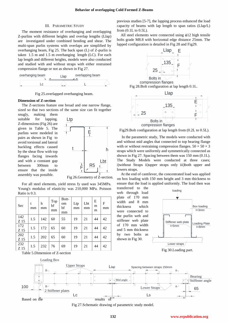
III. PARAMETRIC STUDY
The moment resistance of overhanging and overlapping
Z-purlins with different heights and overlap lengths (Llap)
are investigated under combined bending and shear. The
multi-span purlin systems with overlaps are simplified by
overhanging beam, Fig 25. The back span (L) of Z-purlin is
taken 1.5 m and 1.5 m overhanging length (LC). For each
lap length and different heights, models were also conducted
and studied with and without straps with either restrained
compression flange or not as shown in Fig 27.
Dimension of Z-section
The Z-sections feature one broad and one narrow flange,
sized so that two sections of the same size can fit together
snugly, making them
suitable for lapping.
Z-dimensions (Fig 26) are
given in Table 5. The
purlins were modeled in
pairs as shown in Fig to
avoid torsional and lateral
buckling effects caused
by the shear flow with top
flanges facing inwards
and with a constant gap
between 300mm to
ensure that the inside
assembly was possible.
For all steel elements, yield stress fy used was 345MPa.
Young's modulus of elasticity was 210,000 MPa. Poisson
Ratio is 0.3.
Table 5.Dimension of Z-section
Based on the results of
previous studies [5-7], the lapping process enhanced the load
capacity of beams with lap length to span ratios (Llap/L)
from (0.1L to 0.5L).
All steel elements were connected using ϕ12 high tensile
bolts grade M8.8 with horizontal edge distance 25mm. The
lapped configuration is detailed in Fig 28 and Fig29.
In the parametric study, The models were conducted with
and without mid angles that connected to top bearing flange
with or without restraining compression flanges. 50 × 50 × 3
straps which were uniformly and symmetrically connected as
shown in Fig 27. Spacing between them was 150 mm (0.1L).
The Study Models were conducted at three cases;
i)without Straps ii)upper straps only iii)both upper and
lowers straps.
At the end of cantilever, the concentrated load was applied
on box loading with 150 mm height and 3 mm thickness to
ensure that the load is applied uniformly. The load then was
transferred to the
web through load
plate of 170 mm
width and 8 mm
thickness which
were connected to
the purlin web and
stiffener web plate
of 170 mm width
and 5 mm thickness
by two bolts as
shown in Fig 30.
Sec t
mm
h
mm
Top
bf
mm
Bott-
om
bf
mm
Ltp
mm
Lbt
mm
E
m
m
F
mm
142
Z 15 1.5 142 60 55 19 21 44 42
172
Z 15 1.5 172 65 60 19 21 44 42
202
Z 15 1.5 202 65 60 19 21 44 42
232
Z 15 1.5 232 76 69 19 21 44 42
Fig 26.Geometry of Z-section.
Lc Lb
Llap Spacing between straps 150mm
100
Upper Straps
Lower Straps
Mid angle
65
Loading Box
2 Stiffener plates
B
B
A
A
Bearing
Stiffener angle
Fig 25.overlapped overhanging beam.
Llap
Bolts incompression flanges
135
25
E
F
Fig 28.Bolt configuration at lap length 0.1L.
Fig 30.Loading part.
Fig 27.Schematic drawing of parametric study model.
Fig29.Bolt configuration at lap length from (0.2L to 0.5L).
International Journal of Engineering and Technical Research (IJETR)
ISSN: 2321-0869, Volume-2, Issue-11, November 2014
133 www.erpublication.org
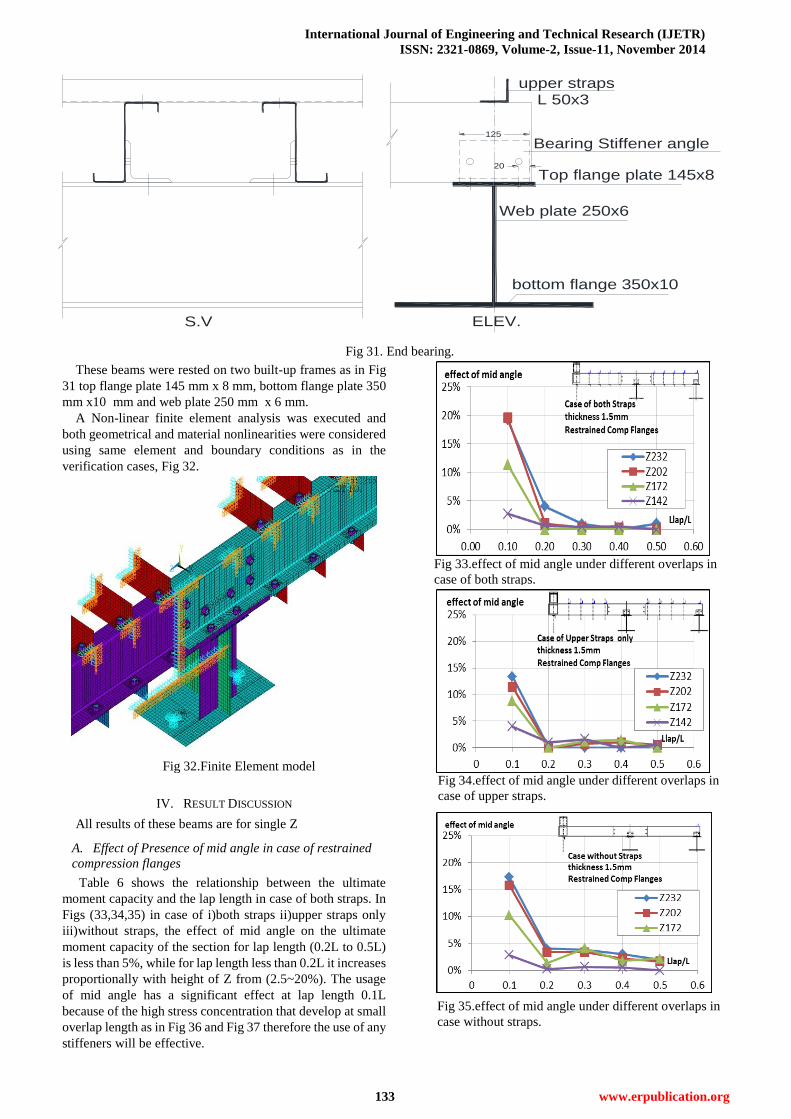
Fig 34.effect of mid angle under different overlaps in
case of upper straps.
These beams were rested on two built-up frames as in Fig
31 top flange plate 145 mm x 8 mm, bottom flange plate 350
mm x10 mm and web plate 250 mm x 6 mm.
A Non-linear finite element analysis was executed and
both geometrical and material nonlinearities were considered
using same element and boundary conditions as in the
verification cases, Fig 32.
IV. RESULT DISCUSSION
All results of these beams are for single Z
A. Effect of Presence of mid angle in case of restrained
compression flanges
Table 6 shows the relationship between the ultimate
moment capacity and the lap length in case of both straps. In
Figs (33,34,35) in case of i)both straps ii)upper straps only
iii)without straps, the effect of mid angle on the ultimate
moment capacity of the section for lap length (0.2L to 0.5L)
is less than 5%, while for lap length less than 0.2L it increases
proportionally with height of Z from (2.5~20%). The usage
of mid angle has a significant effect at lap length 0.1L
because of the high stress concentration that develop at small
overlap length as in Fig 36 and Fig 37 therefore the use of any
stiffeners will be effective.
Bearing Stiffener angle
Top flange plate 145x8
Web plate 250x6
bottom flange 350x10
S.V ELEV.
upper strapsL 50x3
125
20
Fig 32.Finite Element model
Fig 31. End bearing.
Fig 33.effect of mid angle under different overlaps in
case of both straps.
Fig 35.effect of mid angle under different overlaps in
case without straps.

Behavior of overlapping Cold Formed Z-Beams
134 www.erpublication.org
Table 6.Results of different lap lengths in case of both straps.
B. Effect of restraining compression flanges in presence of
mid angle
The effect of restraining compression flanges using two
bolts is directly proportional to the height as in figures 38-40.
i)in case of both straps (Table 7), it slightly affect the
maximum moment within 0~7% for lap length ranging from
(0.2L to 0.5L) and this effect increases for lap length less than
0.2L up to 20% . ii)in both cases of using upper straps or
without straps, restraining compression flanges has a
significant effect especially on lap length less than 0.2L up to
40% and from(5~25)% for lap length ranging from (0.2L to
0.5L). The effect of restraining compression is also inversely
proportional to the overlap length. But this inversed in case of
i) upper straps only, from lap length 0.4L (Fig 38). Ii) in case
without straps, from lap length 0.3L (Fig 39). It can be
concluded that restraining the compression flanges is more
effective in case of upper straps only or without straps as the
failure modes in these cases is due to distortional buckling in
bottom flanges as shown in Fig 41-43 so using bolts at
compression flanges restrained them as shown in Fig 44-46.
Table 7.Results of different lap lengths with both straps
Model Llap
Lap
length
mm
with mid
angle
without mid
angle
Moment
capacity
(m.t)
Moment
capacity (m.t)
Z232
0.1L 150 1.28 1.08
0.2L 300 1.40 1.35
0.3L 450 1.51 1.49
0.4L 600 1.62 1.63
0.5L 750 1.74 1.72
Z202
0.1L 150 1.05 0.88
0.2L 300 1.15 1.14
0.3L 450 1.25 1.24
0.4L 600 1.35 1.34
0.5L 750 1.46 1.45
Z172
0.1L 150 0.84 0.75
0.2L 300 0.96 0.96
0.3L 450 1.04 1.04
0.4L 600 1.14 1.13
0.5L 750 1.23 1.23
Z142
0.1L 150 0.61 0.60
0.2L 300 0.74 0.73
0.3L 450 0.81 0.81
0.4L 600 0.88 0.88
0.5L 750 0.95 0.95 Model
Lap length
(mm)
Restrained
comp.
flanges
unrestrained
comp flanges
Moment
capacity
(m.t)
Moment
capacity
(m.t)
Z232
150 1.28 1.01
300 1.40 1.31
450 1.51 1.46
600 1.62 1.59
750 1.74 1.72
Z202
150 1.05 0.86
300 1.15 1.10
450 1.25 1.22
600 1.35 1.34
750 1.46 1.45
Z172
150 0.84 0.72
300 0.96 0.92
450 1.04 1.02
600 1.14 1.12
750 1.23 1.21
Z142
150 0.61 0.57
300 0.74 0.71
450 0.81 0.79
600 0.88 0.87
750 0.95 0.94
Fig 37.Failure mode of from (0.2L to 0.5L) with and
without mid angle.
Fig 36.Failure mode of 0.1L with and without mid angle.
International Journal of Engineering and Technical Research (IJETR)
ISSN: 2321-0869, Volume-2, Issue-11, November 2014
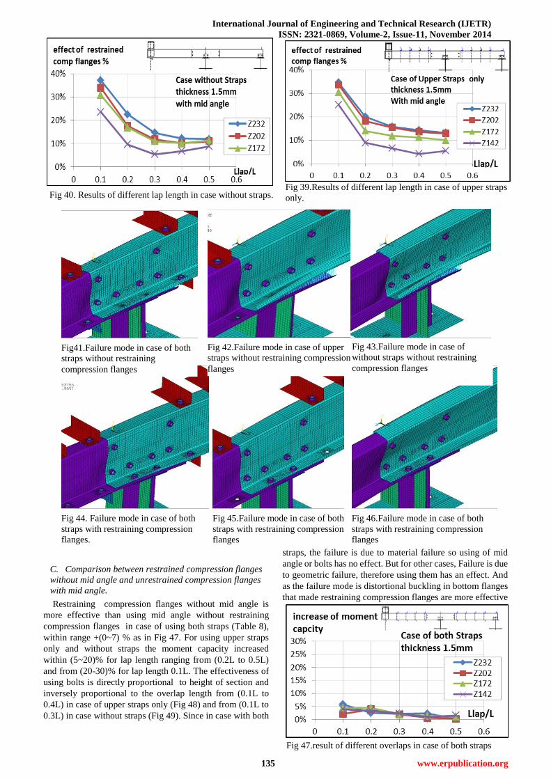
135 www.erpublication.org
Fig 39.Results of different lap length in case of upper straps
only.
Fig 47.result of different overlaps in case of both straps
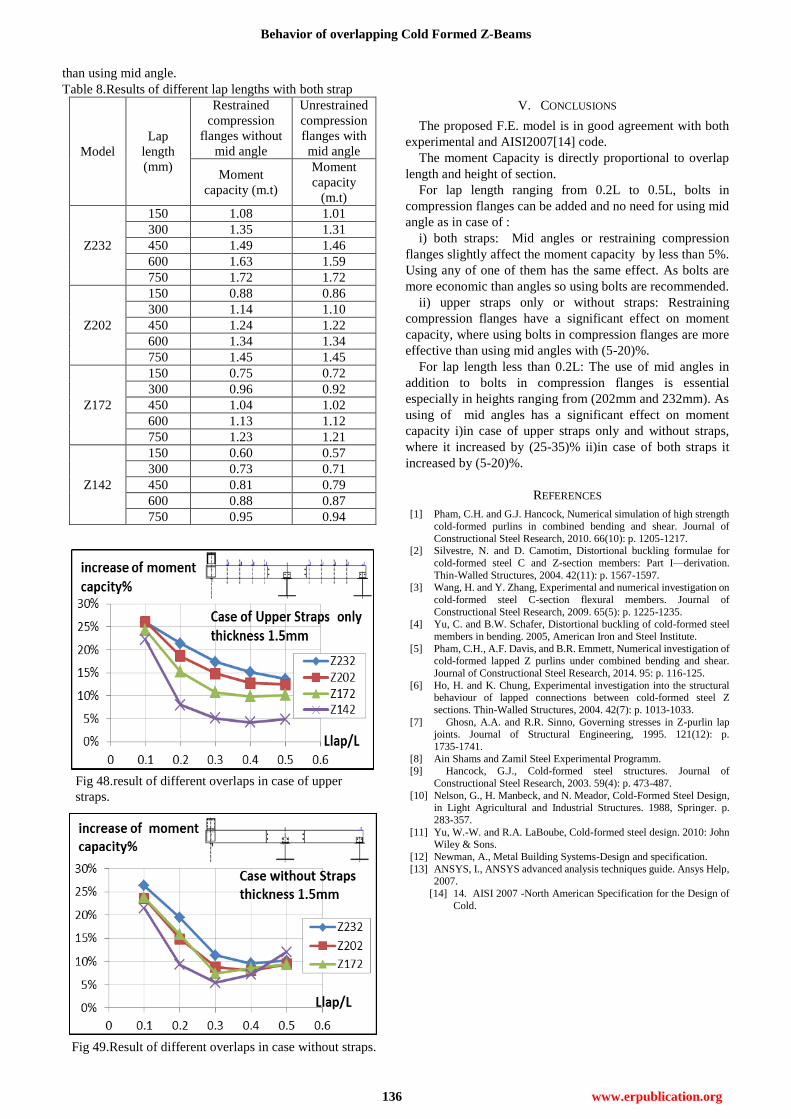
C. Comparison between restrained compression flanges
without mid angle and unrestrained compression flanges
with mid angle.
Restraining compression flanges without mid angle is
more effective than using mid angle without restraining
compression flanges in case of using both straps (Table 8),
within range +(0~7) % as in Fig 47. For using upper straps
only and without straps the moment capacity increased
within (5~20)% for lap length ranging from (0.2L to 0.5L)
and from (20-30)% for lap length 0.1L. The effectiveness of
using bolts is directly proportional to height of section and
inversely proportional to the overlap length from (0.1L to
0.4L) in case of upper straps only (Fig 48) and from (0.1L to
0.3L) in case without straps (Fig 49). Since in case with both
straps, the failure is due to material failure so using of mid
angle or bolts has no effect. But for other cases, Failure is due
to geometric failure, therefore using them has an effect. And
as the failure mode is distortional buckling in bottom flanges
that made restraining compression flanges are more effective
Fig 45.Failure mode in case of both
straps with restraining compression
flanges
Fig 44. Failure mode in case of both
straps with restraining compression
flanges.
Fig 46.Failure mode in case of both
straps with restraining compression
flanges
Fig 40. Results of different lap length in case without straps.
Fig41.Failure mode in case of both
straps without restraining
compression flanges
Fig 42.Failure mode in case of upper
straps without restraining compression
flanges
Fig 43.Failure mode in case of
without straps without restraining
compression flanges
Behavior of overlapping Cold Formed Z-Beams
136 www.erpublication.org
Fig 48.result of different overlaps in case of upper
straps.
than using mid angle.
Table 8.Results of different lap lengths with both strap
V. CONCLUSIONS
The proposed F.E. model is in good agreement with both
experimental and AISI2007[14] code.
The moment Capacity is directly proportional to overlap
length and height of section.
For lap length ranging from 0.2L to 0.5L, bolts in
compression flanges can be added and no need for using mid
angle as in case of :
i) both straps: Mid angles or restraining compression
flanges slightly affect the moment capacity by less than 5%.
Using any of one of them has the same effect. As bolts are
more economic than angles so using bolts are recommended.
ii) upper straps only or without straps: Restraining
compression flanges have a significant effect on moment
capacity, where using bolts in compression flanges are more
effective than using mid angles with (5-20)%.
For lap length less than 0.2L: The use of mid angles in
addition to bolts in compression flanges is essential
especially in heights ranging from (202mm and 232mm). As
using of mid angles has a significant effect on moment
capacity i)in case of upper straps only and without straps,
where it increased by (25-35)% ii)in case of both straps it
increased by (5-20)%.
REFERENCES
[1] Pham, C.H. and G.J. Hancock, Numerical simulation of high strength
cold-formed purlins in combined bending and shear. Journal of
Constructional Steel Research, 2010. 66(10): p. 1205-1217. [2] Silvestre, N. and D. Camotim, Distortional buckling formulae for
cold-formed steel C and Z-section members: Part I—derivation.
Thin-Walled Structures, 2004. 42(11): p. 1567-1597. [3] Wang, H. and Y. Zhang, Experimental and numerical investigation on
cold-formed steel C-section flexural members. Journal of
Constructional Steel Research, 2009. 65(5): p. 1225-1235.
[4] Yu, C. and B.W. Schafer, Distortional buckling of cold-formed steel
members in bending. 2005, American Iron and Steel Institute.
[5] Pham, C.H., A.F. Davis, and B.R. Emmett, Numerical investigation of cold-formed lapped Z purlins under combined bending and shear.
Journal of Constructional Steel Research, 2014. 95: p. 116-125.
[6] Ho, H. and K. Chung, Experimental investigation into the structural behaviour of lapped connections between cold-formed steel Z
sections. Thin-Walled Structures, 2004. 42(7): p. 1013-1033.
[7] Ghosn, A.A. and R.R. Sinno, Governing stresses in Z-purlin lap joints. Journal of Structural Engineering, 1995. 121(12): p.
1735-1741.
[8] Ain Shams and Zamil Steel Experimental Programm. [9] Hancock, G.J., Cold-formed steel structures. Journal of
Constructional Steel Research, 2003. 59(4): p. 473-487.
[10] Nelson, G., H. Manbeck, and N. Meador, Cold-Formed Steel Design, in Light Agricultural and Industrial Structures. 1988, Springer. p.
283-357.
[11] Yu, W.-W. and R.A. LaBoube, Cold-formed steel design. 2010: John Wiley & Sons.
[12] Newman, A., Metal Building Systems-Design and specification.
[13] ANSYS, I., ANSYS advanced analysis techniques guide. Ansys Help, 2007.
[14] 14. AISI 2007 -North American Specification for the Design of
Cold.
Model
Lap
length
(mm)
Restrained
compression
flanges without
mid angle
Unrestrained
compression
flanges with
mid angle
Moment
capacity (m.t)
Moment
capacity
(m.t)
Z232
150 1.08 1.01
300 1.35 1.31
450 1.49 1.46
600 1.63 1.59
750 1.72 1.72
Z202
150 0.88 0.86
300 1.14 1.10
450 1.24 1.22
600 1.34 1.34
750 1.45 1.45
Z172
150 0.75 0.72
300 0.96 0.92
450 1.04 1.02
600 1.13 1.12
750 1.23 1.21
Z142
150 0.60 0.57
300 0.73 0.71
450 0.81 0.79
600 0.88 0.87
750 0.95 0.94
Fig 49.Result of different overlaps in case without straps.


![[STEEL Structure] Design Guide for Cold-Formed Steel Beams With Web Penetration - AISI - US 0906](https://img.pdfslide.net/doc/110x75/55cfea4e5503467d968bd1bc/steel-structure-design-guide-for-cold-formed-steel-beams-with-web-penetration.jpg)