Embed Size (px)
Citation preview
Journal of Civil Engineering and Architecture 10 (2016) 53-63 doi: 10.17265/1934-7359/2016.01.006
Behavior of Reinforced Concrete Columns under
Combined Axial Load and Bending in Accordance with a
Nonlinear Numerical Model
Carlos Eduardo Luna de Melo1 and Guilherme Sales Soares de Azevedo Melo2 1. Department of Technology, Faculty of Architecture and Urbanism, University of Brasília , Brasília 70910-900, Brazil
2. Department of Civil Engineering and Environmental, Faculty of Technology, University of Brasília , Brasília 70910-900, Brazil
Abstract: A nonlinear numerical model was developed to analyze reinforced concrete columns under combined axial load and bending up to failure. Results of reinforced concrete columns under eccentric compression tested to failure are presented and compared to results from a numerical nonlinear model. The tests involved 10 columns with cross-section of 250 mm × 120 mm, geometrical reinforcement ratio of 1.57% and concrete with compression strength around 40 MPa, with 3,000 mm in length. The main variable was the load eccentricity in the direction of the smaller dimension of cross-section. Experimental results of ultimate load and of the evolution of transverse displacements and concrete strains are compared with the numerical results. The estimated results obtained by the numerical model are close to the experimental ones, being suitable for use in verification of elements under combined axial load and bending. Key words: Columns, reinforced concrete, combined axial load and bending, numerical analysis.
1. Introduction
Reinforced concrete columns are important structural elements, which, in a standard structure of building, have main function of supporting horizontal and vertical loads, transmitting these loads to foundations.
With the advent of the computers and high performance concretes, concrete structures became slenderer, with better use of concrete and reinforcement strength. Among the consequences of that technological advance, there is great likeliness to reach a limit state of instability of the columns.
The complexity of study of reinforced concrete elements under axial load and bending is due to its nonlinear behavior. The physical nonlinearity due to reinforced concrete and reinforcement constitutive nonlinear equations, the geometrical nonlinearity due
Corresponding author: Carlos Eduardo Luna de Melo, Ph.D., professor, research fields: structural engineering, numerical and experimental tests, reinforced and prestressed concrete structures.
to iteration between internal forces and displacements due to load, lead to simplified or iterative solutions.
Knowing the behavior of columns under combined axial load and bending during loads steps until failure is very important, mainly in slender columns, where the second order effects are significant. Experimental studies are difficult to be done, and it is necessary to resort a cross section reduction of the column in order to avoid costs with frame tests and equipment, and consequently becoming a medium proportion test.
Having a numerical model to analyze reinforced concrete columns under combined axial load and bending is important to predict, to analyze test results and to design columns.
A nonlinear numerical model was developed based on work presented by Nagato [1], which considers compression field theory given by Vecchio and Collins [2]. The developed numerical model, called “FLECO2C”, considers physical and geometrical nonlinearities.
D DAVID PUBLISHING
54
2. Experim
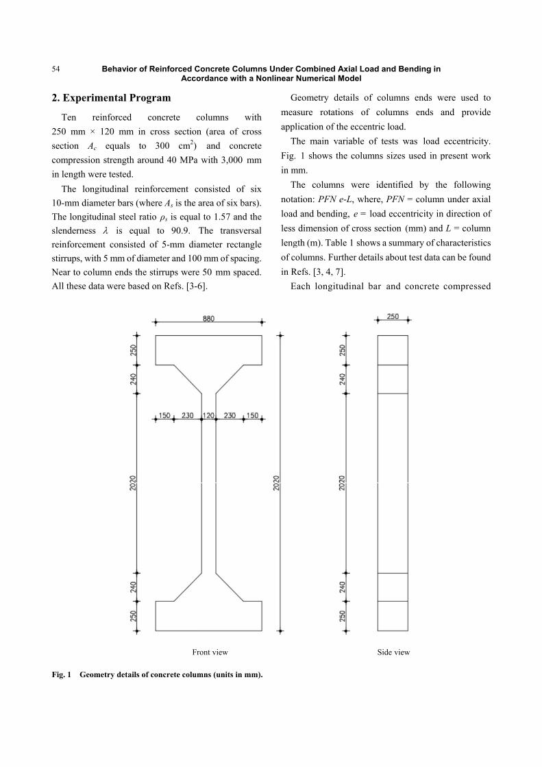
Ten re250 mm × section Ac compressionin length we
The long10-mm diamThe longitudslenderness reinforcemestirrups, withNear to coluAll these dat
Fig. 1 Geom
Behavior of
mental Prog
einforced 120 mm in
equals to n strength aroere tested. gitudinal reinmeter bars (whdinal steel rat is equa
nt consisted h 5 mm of diaumn ends the ta were based
metry details of
f Reinforced CAcc
gram
concrete cross sectio
300 cm2)ound 40 MPa
nforcement chere As is the tio ρs is equa
al to 90.9. of 5-mm di
ameter and 10stirrups were
d on Refs. [3-
f concrete colu
F
Concrete Colordance with
columns won (area of c) and conca with 3,000
consisted of area of six b
al to 1.57 andThe transve
iameter recta00 mm of space 50 mm spa-6].
umns (units in m
Front view
umns Under h a Nonlinear
with cross crete mm
f six ars).
d the ersal
angle cing. aced.
Gmeaapp
TFigin m
Tnotaloadlesslengof cin R
E
mm).
Combined ANumerical M
Geometry deasure rotatio
plication of thThe main var. 1 shows th
mm. The columnsation: PFN ed and bendins dimension ogth (m). Tablcolumns. FurtRefs. [3, 4, 7]Each longitu
Axial Load andModel
tails of coluons of coluhe eccentric loriable of test
he columns si
s were idene-L, where, PFg, e = load eof cross sectie 1 shows a sther details ab.
udinal bar an
Side
d Bending in
umns ends wumns ends oad. ts was load izes used in p
ntified by thPFN = columneccentricity inon (mm) and
summary of chbout test data
nd concrete
view
were used toand provide
eccentricity.present work
he followingn under axialn direction ofd L = columnharacteristicscan be found
compressed
o e
. k
g l f n s d
d
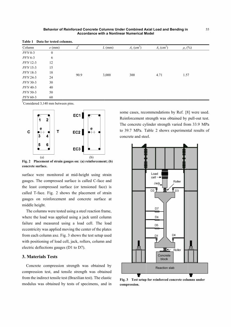
Table 1 Dat
Column PFN 0-3 PFN 6-3 PFN 12-3 PFN 15-3 PFN 18-3 PFN 24-3 PFN 30-3 PFN 40-3 PFN 50-3 PFN 60-3 *Considered 3
(aFig. 2 Placemconcrete surfa
surface wergauges. Thethe least cocalled T-facgauges on middle heigh
The columwhere the lofailure and eccentricity from each cowith positionelectric defle
3. Materia
Concrete compressionfrom the indmodulus wa
Behavior of
ta for tested co
e (mm) 0 6
12 15 18 24 30 40 50 60
,140 mm betwe
a) ment of strain
face.
re monitorede compressedompressed suce. Fig. 2 sh
reinforcemeht.
mns were testeoad was appl
measured uwas applied molumn axe. Fning of load ections gauge
als Tests
compressionn test, and tedirect tensile tas obtained b
f Reinforced CAcc
olumns.
*
90.9
een pins.
gauges on: (a)
d at mid-heid surface is curface (or tehows the plant and conc
ed using a stelied using a jusing a loadmoving the ceig. 3 shows thcell, jack, roles (D1 to D7)
n strength wensile strengest (Brazilian
by tests of sp
Concrete Colordance with
L
3
(b) ) reinforcemen
ight using stcalled C-face ensioned faceacement of stcrete surface
el reaction fraack until colu
d cell. The enter of the plhe test setup ullers, column).
was obtainedgth was obtan test). The elapecimens, an
umns Under h a Nonlinear
L (mm)
,000
nt; (b)
train and
e) is train e at
ame, umn load lates used
n and
d by ained astic
nd in
somReiTheto 3con
Fig.com
Combined ANumerical M
Ac (cm2)
300
me cases, recoinforcement se concrete cy39.7 MPa. Tncrete and ste
. 3 Test setupmpression.
Axial Load andModel
As (cm2)
4.71
ommendationstrength was ylinder strengTable 2 showel.
p for reinforced
Load cell
Concreblock
Reaction
d Bending in
) ρs (%
1.57
ns by Ref. [8obtained by
gth varied frows experimen
d concrete colu
ete k
n slab
55
%)
7
8] were used.pull-out test.
om 33.9 MPantal results of
umns under
5
.
. a f
Behavior of Reinforced Concrete Columns Under Combined Axial Load and Bending in Accordance with a Nonlinear Numerical Model
56
Table 2 Experimental results of concrete and steel.
Column fc (MPa) fct (MPa) Ec (GPa) fy* (MPa) fu
* (MPa) Es* (GPa)
PFN 0-3 35.8 3.1 28.7
595 705 190
PFN 6-3 39.6 2.5 32.1 PFN 12-3 39.6 2.5 32.1 PFN 15-3 35.8 3.1 28.7 PFN 18-3 39.7 2.4 30.6 PFN 24-3 39.7 2.4 30.6 PFN 30-3 33.9 3.3 31.5 PFN 40-3 33.9 3.3 31.5 PFN 50-3 37.6 3.1 31.1 PFN 60-3 37.6 3.1 31.1 *tests results of same lot of material; fc is the highest compressed concrete stress; fct is the highest tensile concrete stress; fy is the tensile yield steel strength; fu is the ultimate tensile steel strength; Es is the steel modulus of elasticity; Ec is the concrete modulus of elasticity.
4. Numerical Model
In order to simulate the columns behavior subjected to combine axial load and bending, a computing program was used, which was developed using Fortran compiler. The numerical model, called FLECO2C, simulates the same tests conditions, applying load in steps until failure. FLECO2C is divided in two parts: a nonlinear physical model, which considers the physical nonlinearities of concrete and reinforcement, and a nonlinear geometric model, which uses the results obtained on nonlinear physical model to calculate the horizontal displacements.
4.1 Consideration of Physical Nonlinearity
The consideration of physical nonlinearity of numerical model was presented by Nagato and Regis [9] and the program was called CACODI. The CACODI program was made using Fortran 77 compiler and the aim was the study of shear resistance of reinforced concrete elements under axial load and bending with different longitudinal reinforcement ratios.
The model is based on compression field theory by Vecchio and Collins [2], which developed a computing program that applies the theory called SMAL (shear
and moment under axial load). For the compressed concrete behavior, the
stress-strain law proposed by Carreira and Chu [10] was adopted:
0
0
c cc
c
f
(1)
0
1
1 c
c
fE
(2)
where, c is the compressed concrete stress; fc is the highest compressed concrete stress; β is the material parameter; c is the compressed concrete strain; 0 is the strain corresponding to the highest compressed concrete strain; E0 is the initial elasticity modulus of concrete.
The variable CT (concrete type) was used in main program to choose the concrete behavior with descendent line or without descendent line (Fig. 4). This law is valid to u ≤ c ≤ 0 to concrete with descendent line (CT = 1), or 0 ≤ c ≤ 0 to concrete without descendent line (CT = 2), which σc = fc, u ≤ c ≤ 0 (Fig. 4). All analyses were done using concrete with descendent line (CT = 1), and the concrete without descendent line was disposed for design purposes.
For the tensioned concrete behavior, a similar law
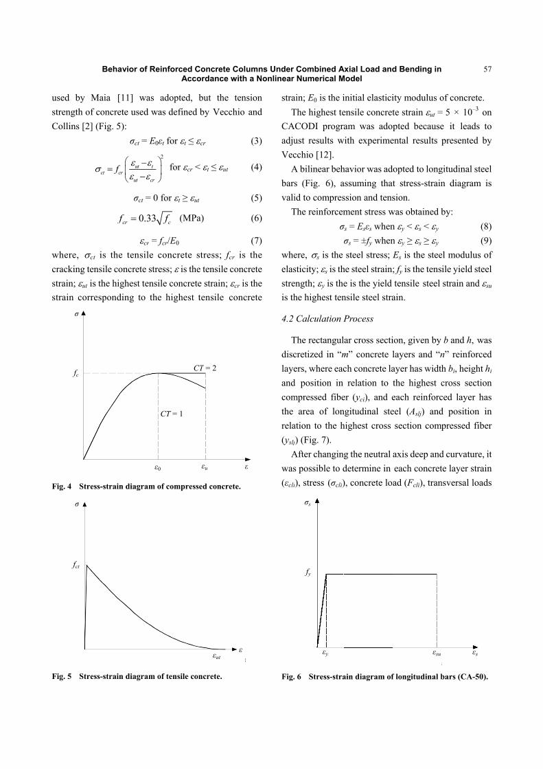
used by Mstrength of cCollins [2] (
where, ct cracking tenstrain; ut is strain corre
Fig. 4 Stress
Fig. 5 Stress
fc
σ
σ
fct
Behavior of
Maia [11] waconcrete used(Fig. 5):
σct =
utct cr
ut
f
σct =
0.3crf
cr
is the tensilnsile concrete the highest tesponding to
s-strain diagra
s-strain diagra
f Reinforced CAcc
as adopted, d was defined
E0εt for t ≤ 2
t
cr
for cr <
= 0 for t ≥ u
33 cf (MP
r = fcr/E0 le concrete stress; is th
ensile concretthe highest
am of compress
am of tensile co
ε0
CT = 1
C
Concrete Colordance with
but the tend by Vecchio
cr
< t ≤ ut
ut
a)
stress; fcr ise tensile concte strain; cr istensile conc
sed concrete.
oncrete.
εu ε
CT = 2
εut ε
umns Under h a Nonlinear
nsion and
(3)
(4)
(5)
(6)
(7) the crete s the crete
straT
CAadjuVec
Abarsvali
T
wheelasstreis th
4.2
Tdisclayeandcomthe rela(yslj
Awas(εcli
Fig.
ε
Combined ANumerical M
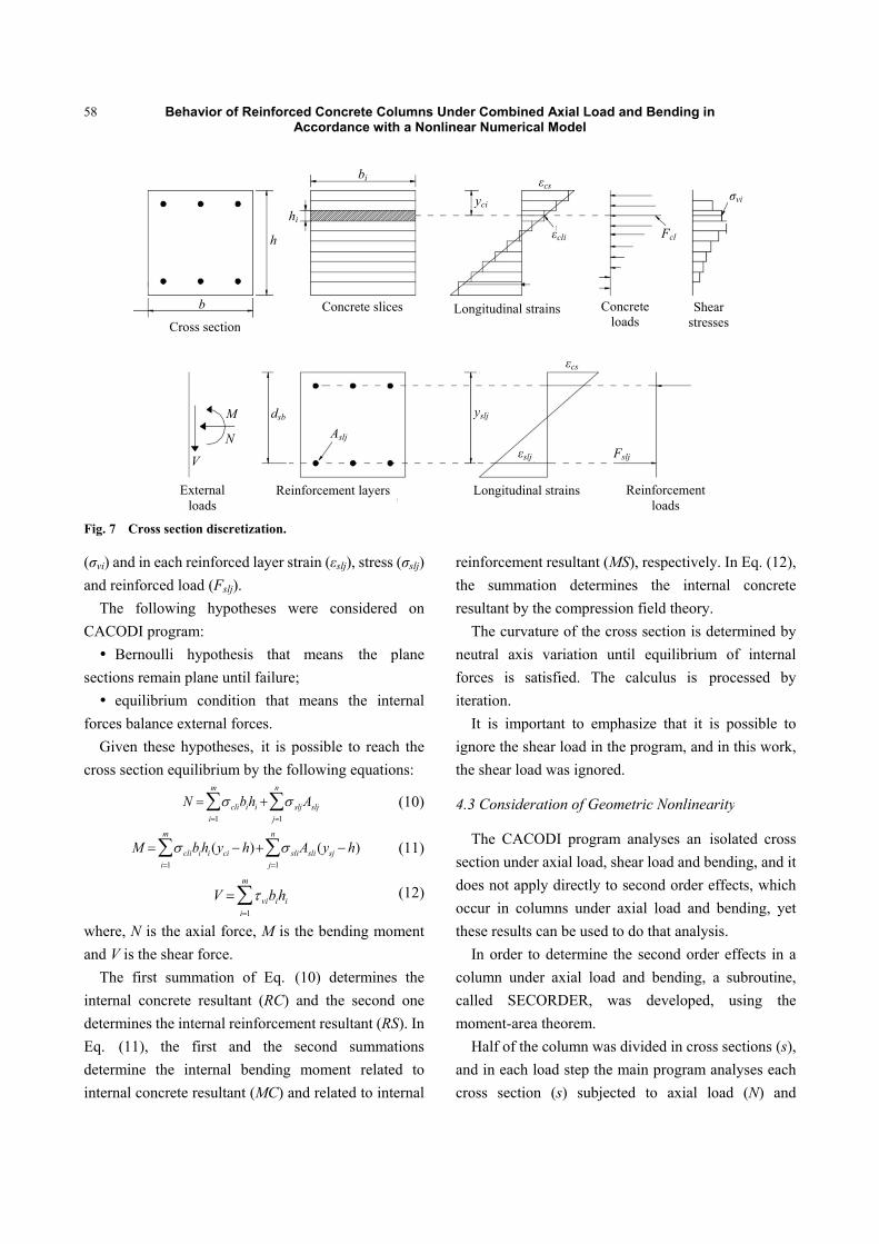
ain; E0 is the iThe highest te
ACODI progrust results wcchio [12]. A bilinear behs (Fig. 6), aid to compresThe reinforcem
σ
ere, s is the sticity; s is thength; y is thehe highest ten
Calculation P
The rectangulcretized in “mers, where eac
d position in mpressed fibe
area of lonation to the hj) (Fig. 7). After changins possible to di), stress (σcli)
. 6 Stress-stra
σs
fy
εy
Axial Load andModel
initial elasticiensile concretam was ado
with experime
havior was adassuming thatssion and tensment stress wσs = Esεs whenσs = ±fy whensteel stress; E
he steel straine is the yield nsile steel stra
Process
lar cross sectim” concrete lch concrete larelation to
er (yci), and engitudinal stehighest cross
g the neutral determine in ), concrete lo
ain diagram of
d Bending in
ity modulus ote strain ut =pted because
ental results p
dopted to longt stress-strainsion.
was obtained bn y < s < y n y ≥ s ≥ y Es is the stee; fy is the tenstensile steel
ain.
ion, given by layers and “nayer has widththe highest ceach reinforceel (Aslj) andsection comp
axis deep andeach concretad (Fcli), tran
f longitudinal b
εsu
57
of concrete.= 5 × 10⁻³ one it leads topresented by
gitudinal steeln diagram is
by: (8) (9)
el modulus ofile yield steelstrain and su
b and h, wasn” reinforcedh bi, height hi
cross sectionced layer hasd position inpressed fiber
d curvature, itte layer strainnsversal loads
bars (CA-50).
εs
7
n o y
l s
) ) f l u
s d i
n s n r
t n s
58
Fig. 7 Cross
(σvi) and in eand reinforc
The folloCACODI pr Bernou
sections rem equilibr
forces balanGiven the
cross section
where, N is and V is the
The first internal condetermines tEq. (11), determine tinternal conc
M
Behavior of
s section discre
each reinforceed load (Fslj)owing hyporogram: ulli hypothesmain plane unt
rium conditince external foese hypothesen equilibrium
the axial forshear force. summation
ncrete resultathe internal rethe first an
the internal crete resultan
N clii1
m
clibihi (yci i1
m
V
Cross section
b
M
N
V
External loads
f Reinforced CAcc
etization.
ed layer strain. theses were
sis that metil failure; ion that meorces. es, it is poss
m by the follow
rce, M is the
of Eq. (10)ant (RC) andeinforcement nd the secobending mo
nt (MC) and r
ibihi slj Asljj1
n
h) sliAsli (j1
n
vibihii1
m
n
h
hi
dsb
Reinforc
Concrete Colordance with
n (εslj), stress (
considered
eans the p
ans the inte
sible to reachwing equation
bending mom
) determines d the second
resultant (RSond summatoment relatedrelated to inte
j
(ysj h)
Concrete slice
bi
Aslj
cement layers
umns Under h a Nonlinear
(σslj)
on
plane
ernal
h the ns:
(10)
(11)
(12)
ment
the one
S). In tions d to ernal
reinthe resu
Tneuforciter
Itignothe
4.3
Tsectdoeoccthes
Incolucallmom
Handcros
es Long
y
L
y
Combined ANumerical M
nforcement resummation
ultant by the cThe curvatureutral axis vaces is satisfation. t is importanore the shear shear load w
Consideratio
The CACODtion under ax
es not apply dur in columnse results cann order to deumn under aled SECORment-area the
Half of the cod in each loadss section (s
gitudinal strains
yci
εcs
ε
Longitudinal str
yslj
εslj
Axial Load andModel
esultant (MS),n determinescompression e of the crossariation until fied. The ca
nt to emphasload in the p
was ignored.
on of Geomet
I program anxial load, sheadirectly to sens under axi
n be used to determine the axial load an
RDER, was eorem. lumn was div
d step the mas) subjected
s
εcli
Concreloads
rains
εcs
Fslj
Re
d Bending in
, respectivelys the internfield theory.
s section is deequilibrium
alculus is p
size that it isprogram, and
tric Nonlinear
nalyses an isar load and becond order eial load and do that analysi
second ordernd bending, a
developed,
vided in crossain program ad to axial lo
Fcl
ete s
Sheastress
einforcement loads
y. In Eq. (12),nal concrete
etermined by
m of internalprocessed by
s possible toin this work,
rity
solated crossending, and itffects, whichbending, yetis. r effects in aa subroutine,
using the
s sections (s),analyses eachoad (N) and
ar ses
σvi
, e
y l y
o ,
s t h t
a , e
, h d
Behavior of Reinforced Concrete Columns Under Combined Axial Load and Bending in Accordance with a Nonlinear Numerical Model
59
bending (M), given by the following Eq. (13): Ms = N·(e + δ(i − 1, s)) (13)
where, e is the initial eccentricity, δ(i − 1, s) is the column horizontal displacement of section (s) determined on the previous iteration (i − 1).
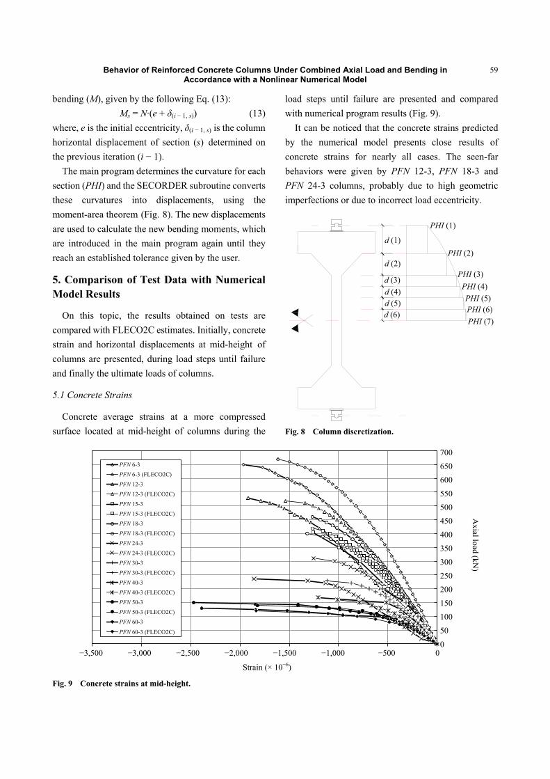
The main program determines the curvature for each section (PHI) and the SECORDER subroutine converts these curvatures into displacements, using the moment-area theorem (Fig. 8). The new displacements are used to calculate the new bending moments, which are introduced in the main program again until they reach an established tolerance given by the user.
5. Comparison of Test Data with Numerical Model Results
On this topic, the results obtained on tests are compared with FLECO2C estimates. Initially, concrete strain and horizontal displacements at mid-height of columns are presented, during load steps until failure and finally the ultimate loads of columns.
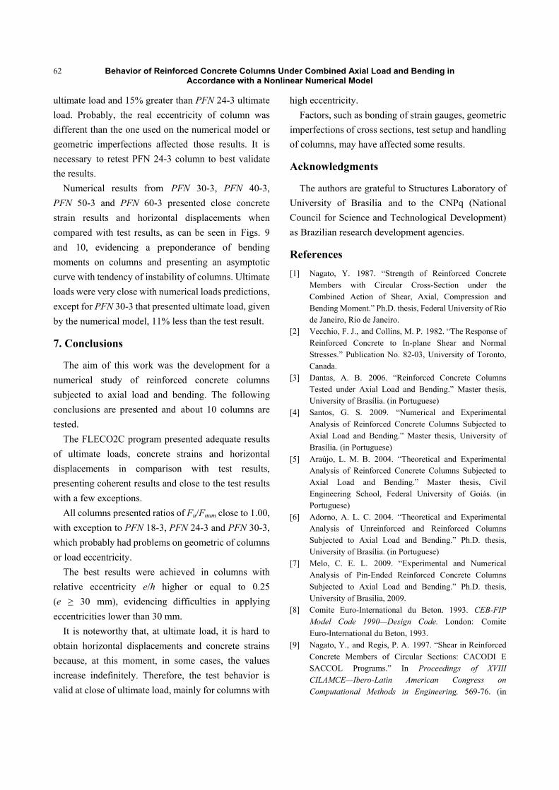
5.1 Concrete Strains
Concrete average strains at a more compressed surface located at mid-height of columns during the
load steps until failure are presented and compared with numerical program results (Fig. 9).
It can be noticed that the concrete strains predicted by the numerical model presents close results of concrete strains for nearly all cases. The seen-far behaviors were given by PFN 12-3, PFN 18-3 and PFN 24-3 columns, probably due to high geometric imperfections or due to incorrect load eccentricity.
Fig. 8 Column discretization.
Fig. 9 Concrete strains at mid-height.
PHI(1)
PHI(2)
PHI(3)PHI(4)PHI(5)PHI(6)PHI(7)
d(1)
d(2)
d(3)d(4)d(5)d(6)
0
50
100
150
200
250
300
350
400
450
500
550
600
650
700
-3500 -3000 -2500 -2000 -1500 -1000 -500 0
Ax
ial l
oa
d (
kN)
Strain (x10-6)
PFN 6-3
PFN 6-3 (FLECO2C)
PFN 12-3
PFN 12-3 (FLECO2C)
PFN 15-3
PFN 15-3 (FLECO2C)
PFN 18-3
PFN 18-3 (FLECO2C)
PFN 24-3
PFN 24-3 (FLECO2C)
PFN 30-3
PFN 30-3 (FLECO2C)
PFN 40-3
PFN 40-3 (FLECO2C)
PFN 50-3
PFN 50-3 (FLECO2C)
PFN 60-3
PFN 60-3 (FLECO2C)
PHI (1)
PHI (2)
PHI (3) PHI (4) PHI (5) PHI (6) PHI (7)
d (1)
d (2)
d (3) d (4) d (5) d (6)
PFN 6-3 PFN 6-3 (FLECO2C) PFN 12-3 PFN 12-3 (FLECO2C) PFN 15-3 PFN 15-3 (FLECO2C) PFN 18-3 PFN 18-3 (FLECO2C) PFN 24-3 PFN 24-3 (FLECO2C) PFN 30-3 PFN 30-3 (FLECO2C) PFN 40-3 PFN 40-3 (FLECO2C) PFN 50-3 PFN 50-3 (FLECO2C) PFN 60-3
PFN 60-3 (FLECO2C)
700
650
600
550
500
450
400
350
300
250 200
150
100
50
0 −3,500 −3,000 −2,500 −2,000 −1,500 −1,000 −500 0
Strain (× 10−6)
Axial load (kN
)
Behavior of Reinforced Concrete Columns Under Combined Axial Load and Bending in Accordance with a Nonlinear Numerical Model
60
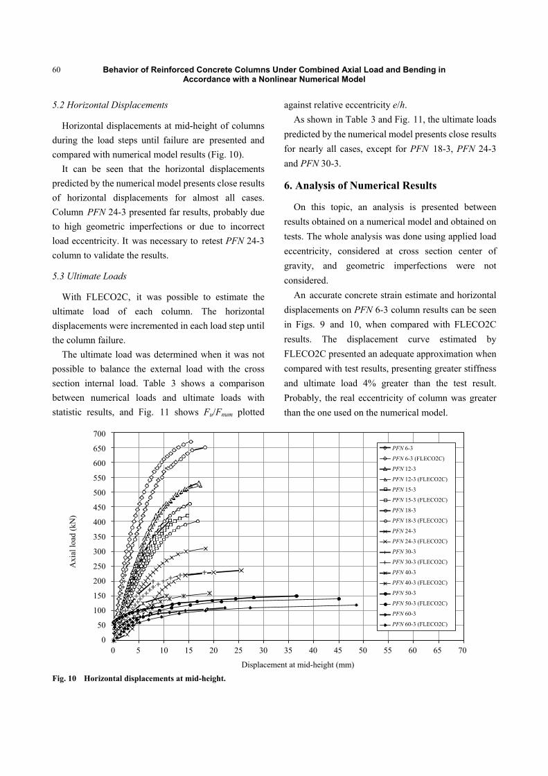
5.2 Horizontal Displacements
Horizontal displacements at mid-height of columns during the load steps until failure are presented and compared with numerical model results (Fig. 10).
It can be seen that the horizontal displacements predicted by the numerical model presents close results of horizontal displacements for almost all cases. Column PFN 24-3 presented far results, probably due to high geometric imperfections or due to incorrect load eccentricity. It was necessary to retest PFN 24-3 column to validate the results.
5.3 Ultimate Loads
With FLECO2C, it was possible to estimate the ultimate load of each column. The horizontal displacements were incremented in each load step until the column failure.
The ultimate load was determined when it was not possible to balance the external load with the cross section internal load. Table 3 shows a comparison between numerical loads and ultimate loads with statistic results, and Fig. 11 shows Fu/Fnum plotted
against relative eccentricity e/h. As shown in Table 3 and Fig. 11, the ultimate loads
predicted by the numerical model presents close results for nearly all cases, except for PFN 18-3, PFN 24-3 and PFN 30-3.
6. Analysis of Numerical Results
On this topic, an analysis is presented between results obtained on a numerical model and obtained on tests. The whole analysis was done using applied load eccentricity, considered at cross section center of gravity, and geometric imperfections were not considered.
An accurate concrete strain estimate and horizontal displacements on PFN 6-3 column results can be seen in Figs. 9 and 10, when compared with FLECO2C results. The displacement curve estimated by FLECO2C presented an adequate approximation when compared with test results, presenting greater stiffness and ultimate load 4% greater than the test result. Probably, the real eccentricity of column was greater than the one used on the numerical model.
Fig. 10 Horizontal displacements at mid-height.
0
50
100
150
200
250
300
350
400
450
500
550
600
650
700
0 5 10 15 20 25 30 35 40 45 50 55 60 65 70
Ax
ial l
oa
d (
kN
)
Displacement at mid-height (mm)
PFN 6-3
PFN 6-3 (FLECO2C)
PFN 12-3
PFN 12-3 (FLECO2C)
PFN 15-3
PFN 15-3 (FLECO2C)
PFN 18-3
PFN 18-3 (FLECO2C)
PFN 24-3
PFN 24-3 (FLECO2C)
PFN 30-3
PFN 30-3 (FLECO2C)
PFN 40-3
PFN 40-3 (FLECO2C)
PFN 50-3
PFN 50-3 (FLECO2C)
PFN 60-3
PFN 60-3 (FLECO2C)
PFN 6-3
PFN 6-3 (FLECO2C)
PFN 12-3
PFN 12-3 (FLECO2C)
PFN 15-3
PFN 15-3 (FLECO2C)
PFN 18-3
PFN 18-3 (FLECO2C)
PFN 24-3
PFN 24-3 (FLECO2C)
PFN 30-3
PFN 30-3 (FLECO2C)
PFN 40-3
PFN 40-3 (FLECO2C)
PFN 50-3
PFN 50-3 (FLECO2C)
PFN 60-3
PFN 60-3 (FLECO2C)
700
650
600
550
500
450
400
350
300
250
200
150
100
50
0
Axi
al lo
ad (k
N)
0 5 10 15 20 25 30 35 40 45 50 55 60 65 70
Displacement at mid-height (mm)
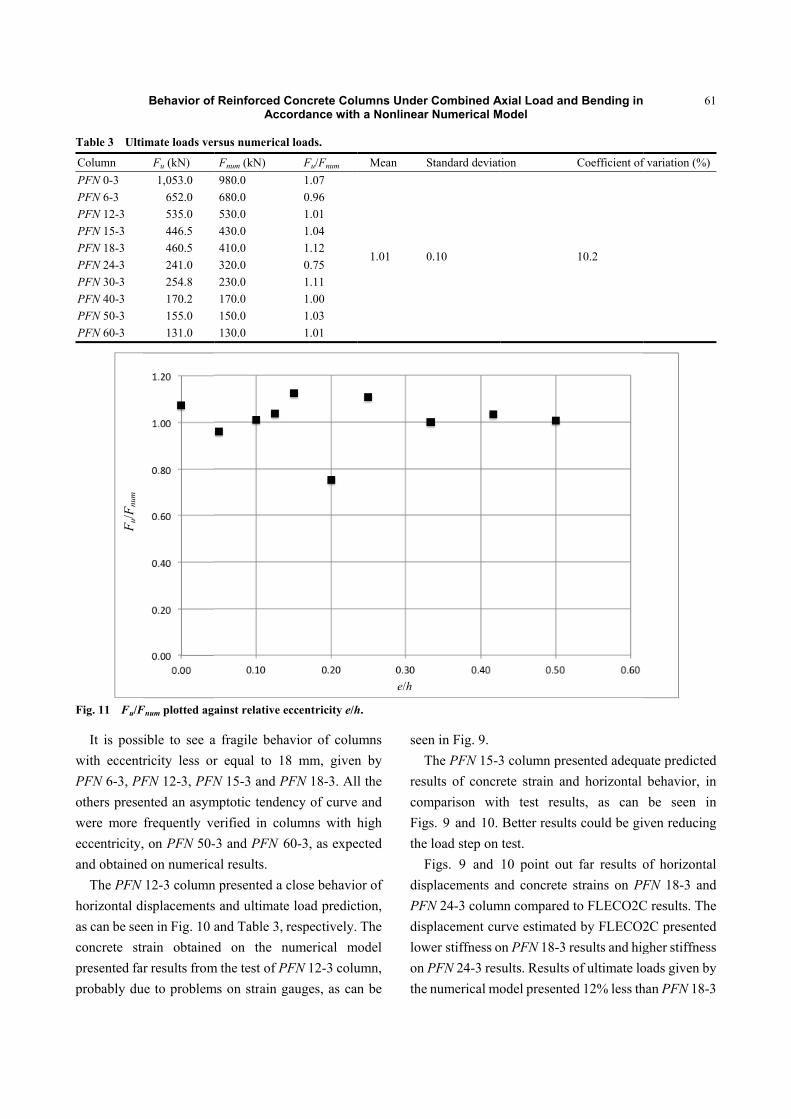
Table 3 Ulti
Column PFN 0-3 PFN 6-3 PFN 12-3 PFN 15-3 PFN 18-3 PFN 24-3 PFN 30-3 PFN 40-3 PFN 50-3 PFN 60-3
Fig. 11 Fu/F
It is posswith eccentrPFN 6-3, PFothers presewere more eccentricity,and obtained
The PFN horizontal das can be seeconcrete strpresented faprobably du
F u/F
num
Behavior of
imate loads ver
Fu (kN) 1,053.0
652.0 535.0 446.5 460.5 241.0 254.8 170.2 155.0 131.0
Fnum plotted aga
ible to see aricity less orFN 12-3, PFNented an asymfrequently ve, on PFN 50-d on numerica12-3 column
displacementsen in Fig. 10 arain obtainer results from
ue to problem
f Reinforced CAcc
rsus numerica
Fnum (kN) 980.0 680.0 530.0 430.0 410.0 320.0 230.0 170.0 150.0 130.0
ainst relative e
a fragile behar equal to 18N 15-3 and P
mptotic tendenerified in co-3 and PFN 6al results.
n presented a s and ultimateand Table 3, d on the n
m the test of Pms on strain g
Concrete Colordance with
l loads.
Fu/Fnum 1.07 0.96 1.01 1.04 1.12 0.75 1.11 1.00 1.03 1.01
eccentricity e/h
avior of colu8 mm, given
PFN 18-3. Allncy of curvelumns with h60-3, as expe
close behavioe load predictrespectively.
numerical mPFN 12-3 colugauges, as can
umns Under h a Nonlinear
Mean S
1.01 0
h.
umns n by l the and
high ected
or of tion, The
model umn, n be
seenT
resucomFigthe
FdispPFNdisplowon Pthe
e/h
Combined ANumerical M
Standard deviat
0.10
n in Fig. 9.The PFN 15-3ults of concrmparison wits. 9 and 10. load step on
Figs. 9 and placements aN 24-3 columplacement cu
wer stiffness oPFN 24-3 resnumerical mo
Axial Load andModel
tion
3 column prerete strain anth test resuBetter resultstest. 10 point out
and concrete mn compared urve estimatedon PFN 18-3 rsults. Results odel presente
d Bending in
Coefficient of
10.2
sented adeqund horizontal lts, as can s could be gi
t far results ostrains on PFto FLECO2C
d by FLECO2results and higof ultimate lo
ed 12% less th
61
f variation (%)
uate predictedbehavior, inbe seen in
ven reducing
of horizontalFN 18-3 and
C results. The2C presentedgher stiffnessoads given byhan PFN 18-3
d n n g
l d e d s y 3
Behavior of Reinforced Concrete Columns Under Combined Axial Load and Bending in Accordance with a Nonlinear Numerical Model
62
ultimate load and 15% greater than PFN 24-3 ultimate load. Probably, the real eccentricity of column was different than the one used on the numerical model or geometric imperfections affected those results. It is necessary to retest PFN 24-3 column to best validate the results.
Numerical results from PFN 30-3, PFN 40-3, PFN 50-3 and PFN 60-3 presented close concrete strain results and horizontal displacements when compared with test results, as can be seen in Figs. 9 and 10, evidencing a preponderance of bending moments on columns and presenting an asymptotic curve with tendency of instability of columns. Ultimate loads were very close with numerical loads predictions, except for PFN 30-3 that presented ultimate load, given by the numerical model, 11% less than the test result.
7. Conclusions
The aim of this work was the development for a numerical study of reinforced concrete columns subjected to axial load and bending. The following conclusions are presented and about 10 columns are tested.
The FLECO2C program presented adequate results of ultimate loads, concrete strains and horizontal displacements in comparison with test results, presenting coherent results and close to the test results with a few exceptions.
All columns presented ratios of Fu/Fnum close to 1.00, with exception to PFN 18-3, PFN 24-3 and PFN 30-3, which probably had problems on geometric of columns or load eccentricity.
The best results were achieved in columns with relative eccentricity e/h higher or equal to 0.25 (e ≥ 30 mm), evidencing difficulties in applying eccentricities lower than 30 mm.
It is noteworthy that, at ultimate load, it is hard to obtain horizontal displacements and concrete strains because, at this moment, in some cases, the values increase indefinitely. Therefore, the test behavior is valid at close of ultimate load, mainly for columns with
high eccentricity. Factors, such as bonding of strain gauges, geometric
imperfections of cross sections, test setup and handling of columns, may have affected some results.
Acknowledgments
The authors are grateful to Structures Laboratory of University of Brasilia and to the CNPq (National Council for Science and Technological Development) as Brazilian research development agencies.
References
[1] Nagato, Y. 1987. “Strength of Reinforced Concrete Members with Circular Cross-Section under the Combined Action of Shear, Axial, Compression and Bending Moment.” Ph.D. thesis, Federal University of Rio de Janeiro, Rio de Janeiro.
[2] Vecchio, F. J., and Collins, M. P. 1982. “The Response of Reinforced Concrete to In-plane Shear and Normal Stresses.” Publication No. 82-03, University of Toronto, Canada.
[3] Dantas, A. B. 2006. “Reinforced Concrete Columns Tested under Axial Load and Bending.” Master thesis, University of Brasília. (in Portuguese)
[4] Santos, G. S. 2009. “Numerical and Experimental Analysis of Reinforced Concrete Columns Subjected to Axial Load and Bending.” Master thesis, University of Brasília. (in Portuguese)
[5] Araújo, L. M. B. 2004. “Theoretical and Experimental Analysis of Reinforced Concrete Columns Subjected to Axial Load and Bending.” Master thesis, Civil Engineering School, Federal University of Goiás. (in Portuguese)
[6] Adorno, A. L. C. 2004. “Theoretical and Experimental Analysis of Unreinforced and Reinforced Columns Subjected to Axial Load and Bending.” Ph.D. thesis, University of Brasília. (in Portuguese)
[7] Melo, C. E. L. 2009. “Experimental and Numerical Analysis of Pin-Ended Reinforced Concrete Columns Subjected to Axial Load and Bending.” Ph.D. thesis, University of Brasilia, 2009.
[8] Comite Euro-International du Beton. 1993. CEB-FIP Model Code 1990—Design Code. London: Comite Euro-International du Beton, 1993.
[9] Nagato, Y., and Regis, P. A. 1997. “Shear in Reinforced Concrete Members of Circular Sections: CACODI E SACCOL Programs.” In Proceedings of XVIII CILAMCE—Ibero-Latin American Congress on Computational Methods in Engineering, 569-76. (in

Behavior of Reinforced Concrete Columns Under Combined Axial Load and Bending in Accordance with a Nonlinear Numerical Model
63
Portuguese) [10] Carreira, D. J., and Chu, K. H. 1985. “Stress-Strain
Relationship for Plain Concrete in Compression.” Journal of the American Concrete Institute 82: 797-804.
[11] Maia, A. C. F. 1979. “Nonlinear Analysis of Reinforced
and Prestressed Concrete Frames in View of the Rheological Behavior of Concrete.” Ph.D. thesis, University Pierre et Marie Currie.
[12] Vecchio, F. 1981. “Response of Reinforced Concrete Subjected to In-plane Shear and Normal Stresses.” Ph.D. thesis, Universityof Toronto.


![Design of Reinforced Concrete Columns[1]](https://img.pdfslide.net/doc/110x75/55cf881055034664618ceef8/design-of-reinforced-concrete-columns1.jpg)
