Embed Size (px)
Citation preview
http://www.iaeme.com/IJCIET/index.asp 1987 [email protected]
International Journal of Civil Engineering and Technology (IJCIET)
Volume 10, Issue 04, April 2019, pp. 1987–2000, Article ID: IJCIET_10_04_198
Available online at http://www.iaeme.com/ijmet/issues.asp?JType=IJCIET&VType=10&IType=4
ISSN Print: 0976-6308 and ISSN Online: 0976-6316
© IAEME Publication Scopus Indexed
BEHAVIOR & STABILITY ANALYSIS OF
GEOGRID REINFORCED EARTHWALL:
A CASE STUDY IN VIZIANAGARAM (A.P)
Abdul Asif Baig
PG Student, Department of Civil Engineering,
Chandigarh University, Punjab, India
Aditya Kumar Tiwary
Assistant Professor, Department of Civil Engineering,
Chandigarh University, Punjab, India
ABSTRACT
Reinforced Earth (RE) wall offers a variety of advantages when compared to
conventional retaining walls and embankments for road approaches. This study is
carried out on proposed RE wall design for an approach road on Visakha side using
finite element based computer program “PLAXIS 2D (version 8.6)”. The proposed
Design which is to be executed in the near future is based on limit-equilibrium
approach. The main aim of this study is to find out the Deformation of this RE wall
along with its Stability using finite element approach. The Global factor of safety of
this Geotechnical structure is also determined using PLAXIS 2D. PLAXIS 2D is a
finite element analytical geotechnical Software which gives accurate results compared
to that finite difference and limit equilibrium analytical software’s. Detailed study of
the Design (using limit-equilibrium approach) acquired from the ongoing project site
is
Key words: Finite Element Analysis, Soft Subgrade, Reinforced Earth Wall, Geo-
Grid Reinforcement, Factor of Safety.
Cite this Article: Abdul Asif Baig and Aditya Kumar Tiwary, Behavior & Stability
Analysis of Geogrid Reinforced Earthwall: A Case Study in Vizianagaram (A.P),
International Journal of Civil Engineering and Technology 10(3), 2019, pp. 1987–
2000.
http://www.iaeme.com/IJCIET/issues.asp?JType=IJCIET&VType=10&IType=3
1. INTRODUCTION
1.1. Reinforced Earth
Reinforced earth is a composite construction material which generally comprises of
cohesionless soil (preferable) and reinforcement. This idea is evolved from the known concept
following in the civil engineering practices, where a composite material of greater strength is
Abdul Asif Baig and Aditya Kumar Tiwary
http://www.iaeme.com/IJCIET/index.asp 1988 [email protected]
developed by combining the materials of different strength characteristics. The reinforced
concrete constructions are examples of such composite materials where the tensile strength of
concrete is enhanced by introducing steel in it. Likewise, soils which have little tensile
strength are strengthened by the inclusion of materials having higher tensile strength. In case
of reinforced earth, the tensile strength is developed through bond resistance which is friction
and depends on surface roughness of reinforcement and soil. If the soil is cohesive, the bond
strength is developed through adhesion.
A variety of materials can be used as reinforcing materials .Those that have been used
successfully include steel, concrete, glass fibre, wood, rubber, aluminium and thermoplastics.
Reinforcement may take the form of strips, grids, anchors & sheet material, chains planks,
rope, vegetation and combinations of these or other material forms.
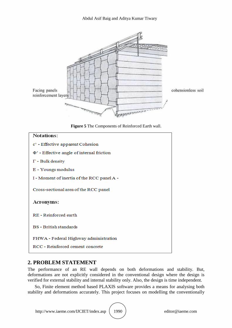
1.1. Reinforced Soil Walls
Reinforced earth walls are the one of the widest applications of reinforced earth and mainly
consists of 3 components. They are cohesionless soil, reinforcement and facing system.The
cohesionless soil should have an angle of internal friction between the compacted fill and the
reinforcing element and not less than 30 degrees. The soil should be predominantly coarse
grained and not more than 10 percent of the particles shall pass 75 micron sieve. The
reinforcement can be of any type and of any form which is already mentioned above in the
reinforced earth.The reinforcing materials generally used in reinforced earth walls are of two
types which are metallic type and synthetic type. Metallic type reinforcement may corrode in
the longer service periods. So, geosynthetics are mostly preferred as reinforcing materials.
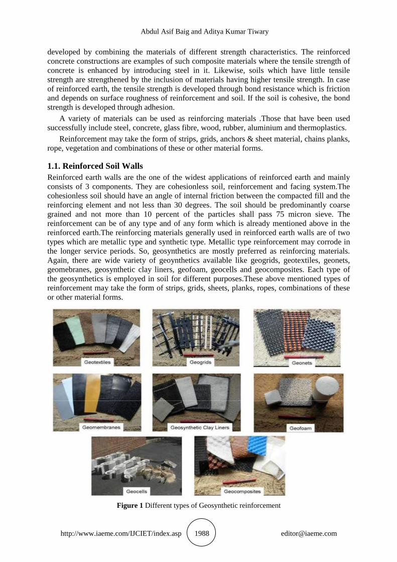
Again, there are wide variety of geoynthetics available like geogrids, geotextiles, geonets,
geomebranes, geosynthetic clay liners, geofoam, geocells and geocomposites. Each type of
the geosynthetics is employed in soil for different purposes.These above mentioned types of
reinforcement may take the form of strips, grids, sheets, planks, ropes, combinations of these
or other material forms.
Figure 1 Different types of Geosynthetic reinforcement
Behavior & Stability Analysis of Geogrid Reinforced Earthwall: A Case Study in Vizianagaram (A.P)
http://www.iaeme.com/IJCIET/index.asp 1989 [email protected]
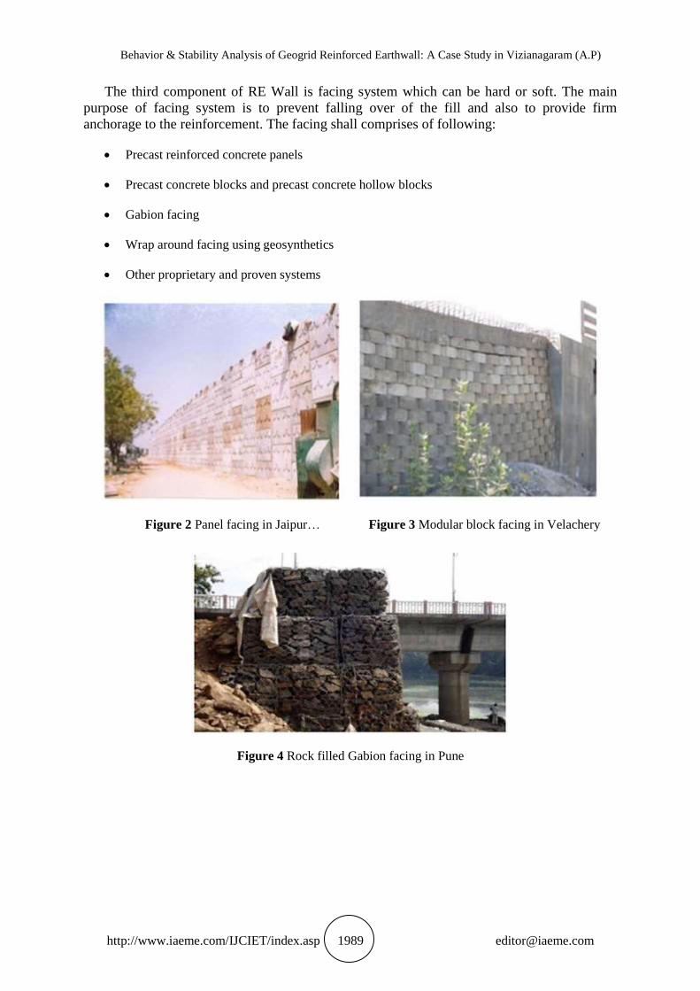
The third component of RE Wall is facing system which can be hard or soft. The main
purpose of facing system is to prevent falling over of the fill and also to provide firm
anchorage to the reinforcement. The facing shall comprises of following:
Precast reinforced concrete panels
Precast concrete blocks and precast concrete hollow blocks
Gabion facing
Wrap around facing using geosynthetics
Other proprietary and proven systems
Figure 2 Panel facing in Jaipur… Figure 3 Modular block facing in Velachery
Figure 4 Rock filled Gabion facing in Pune
Abdul Asif Baig and Aditya Kumar Tiwary
http://www.iaeme.com/IJCIET/index.asp 1990 [email protected]
Figure 5 The Components of Reinforced Earth wall.
2. PROBLEM STATEMENT
The performance of an RE wall depends on both deformations and stability. But,
deformations are not explicitly considered in the conventional design where the design is
verified for external stability and internal stability only. Also, the design is time independent.
So, Finite element method based PLAXIS software provides a means for analysing both
stability and deformations accurately. This project focuses on modelling the conventionally
Behavior & Stability Analysis of Geogrid Reinforced Earthwall: A Case Study in Vizianagaram (A.P)
http://www.iaeme.com/IJCIET/index.asp 1991 [email protected]
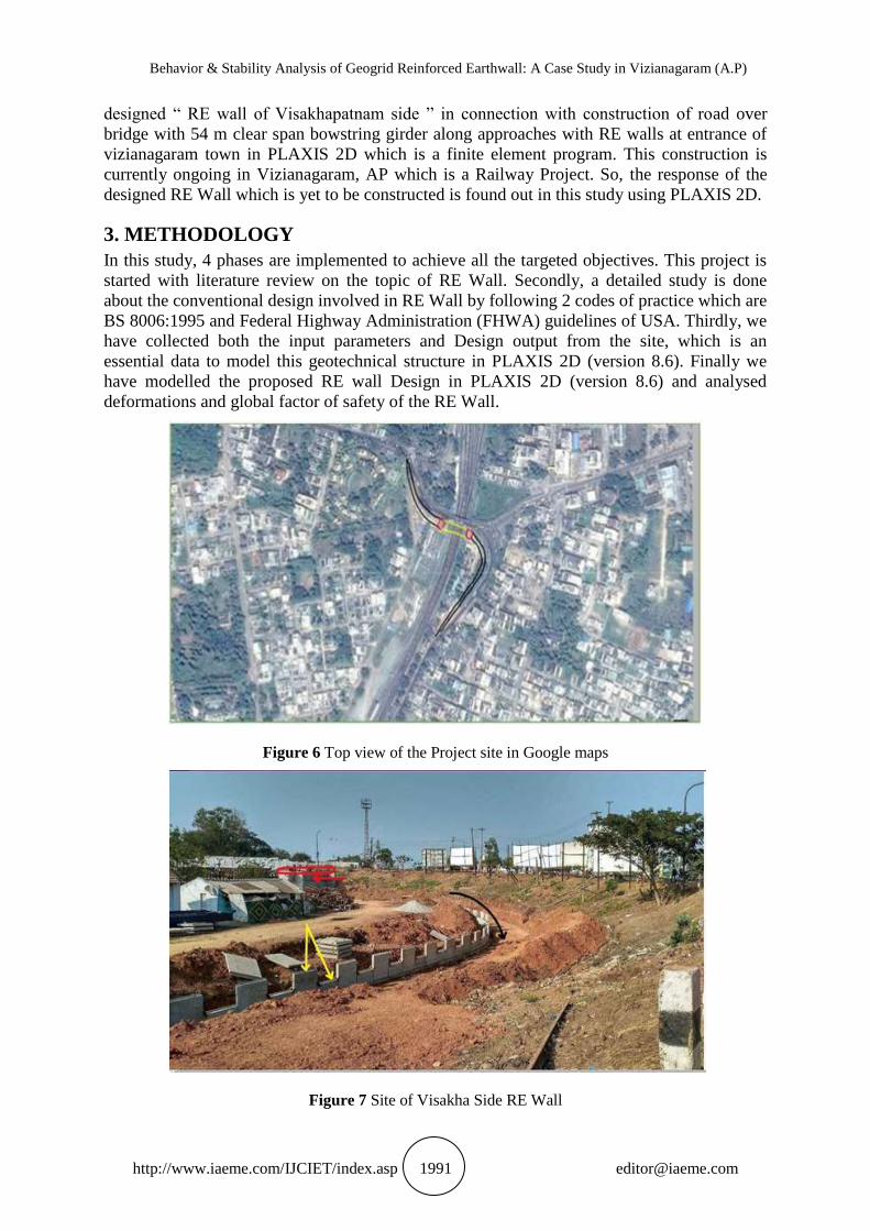
designed “ RE wall of Visakhapatnam side ” in connection with construction of road over
bridge with 54 m clear span bowstring girder along approaches with RE walls at entrance of
vizianagaram town in PLAXIS 2D which is a finite element program. This construction is
currently ongoing in Vizianagaram, AP which is a Railway Project. So, the response of the
designed RE Wall which is yet to be constructed is found out in this study using PLAXIS 2D.
3. METHODOLOGY
In this study, 4 phases are implemented to achieve all the targeted objectives. This project is
started with literature review on the topic of RE Wall. Secondly, a detailed study is done
about the conventional design involved in RE Wall by following 2 codes of practice which are
BS 8006:1995 and Federal Highway Administration (FHWA) guidelines of USA. Thirdly, we
have collected both the input parameters and Design output from the site, which is an
essential data to model this geotechnical structure in PLAXIS 2D (version 8.6). Finally we
have modelled the proposed RE wall Design in PLAXIS 2D (version 8.6) and analysed
deformations and global factor of safety of the RE Wall.
Figure 6 Top view of the Project site in Google maps
Figure 7 Site of Visakha Side RE Wall
Abdul Asif Baig and Aditya Kumar Tiwary
http://www.iaeme.com/IJCIET/index.asp 1992 [email protected]
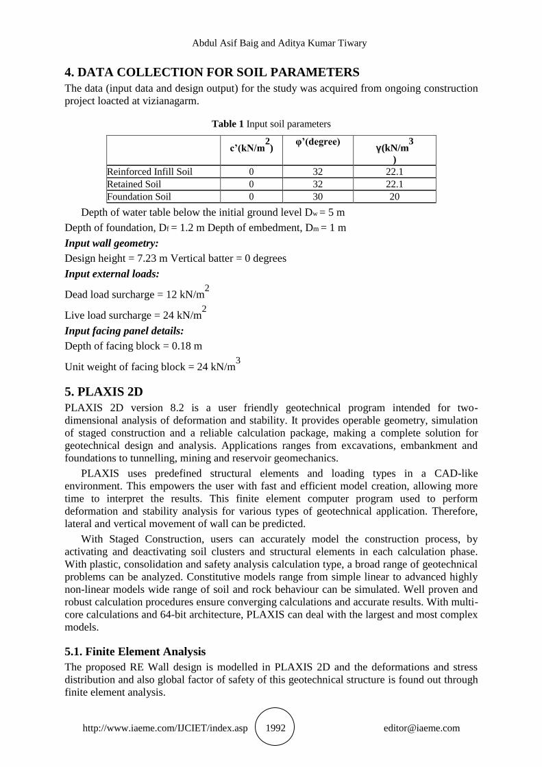
4. DATA COLLECTION FOR SOIL PARAMETERS
The data (input data and design output) for the study was acquired from ongoing construction
project loacted at vizianagarm.
Table 1 Input soil parameters
c’(kN/m
2)
φ’(degree) γ(kN/m
3
)
Reinforced Infill Soil 0 32 22.1
Retained Soil 0 32 22.1
Foundation Soil 0 30 20
Depth of water table below the initial ground level Dw = 5 m
Depth of foundation, Df = 1.2 m Depth of embedment, Dm = 1 m
Input wall geometry:
Design height = 7.23 m Vertical batter = 0 degrees
Input external loads:
Dead load surcharge = 12 kN/m2
Live load surcharge = 24 kN/m2
Input facing panel details:
Depth of facing block = 0.18 m
Unit weight of facing block = 24 kN/m3
5. PLAXIS 2D PLAXIS 2D version 8.2 is a user friendly geotechnical program intended for two-
dimensional analysis of deformation and stability. It provides operable geometry, simulation
of staged construction and a reliable calculation package, making a complete solution for
geotechnical design and analysis. Applications ranges from excavations, embankment and
foundations to tunnelling, mining and reservoir geomechanics.
PLAXIS uses predefined structural elements and loading types in a CAD-like
environment. This empowers the user with fast and efficient model creation, allowing more
time to interpret the results. This finite element computer program used to perform
deformation and stability analysis for various types of geotechnical application. Therefore,
lateral and vertical movement of wall can be predicted.
With Staged Construction, users can accurately model the construction process, by
activating and deactivating soil clusters and structural elements in each calculation phase.
With plastic, consolidation and safety analysis calculation type, a broad range of geotechnical
problems can be analyzed. Constitutive models range from simple linear to advanced highly
non-linear models wide range of soil and rock behaviour can be simulated. Well proven and
robust calculation procedures ensure converging calculations and accurate results. With multi-
core calculations and 64-bit architecture, PLAXIS can deal with the largest and most complex
models.
5.1. Finite Element Analysis
The proposed RE Wall design is modelled in PLAXIS 2D and the deformations and stress
distribution and also global factor of safety of this geotechnical structure is found out through
finite element analysis.
Behavior & Stability Analysis of Geogrid Reinforced Earthwall: A Case Study in Vizianagaram (A.P)
http://www.iaeme.com/IJCIET/index.asp 1993 [email protected]
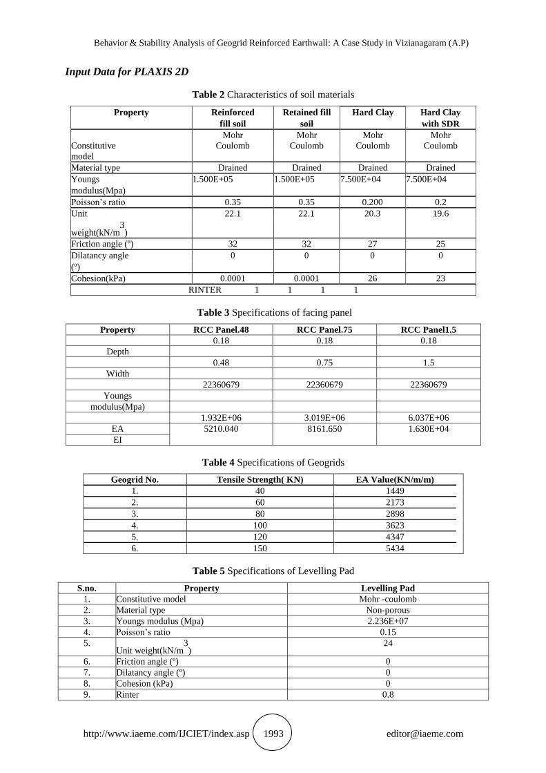
Input Data for PLAXIS 2D
Table 2 Characteristics of soil materials
Property Reinforced Retained fill Hard Clay Hard Clay
fill soil soil with SDR
Mohr Mohr Mohr Mohr
Constitutive Coulomb Coulomb Coulomb Coulomb
model
Material type Drained Drained Drained Drained
Youngs 1.500E+05 1.500E+05 7.500E+04 7.500E+04
modulus(Mpa)
Poisson‟s ratio 0.35 0.35 0.200 0.2
Unit 22.1 22.1 20.3 19.6
weight(kN/m3
)
Friction angle (º) 32 32 27 25
Dilatancy angle 0 0 0 0
(º)
Cohesion(kPa) 0.0001 0.0001 26 23
RINTER 1 1 1 1
Table 3 Specifications of facing panel
Property RCC Panel.48 RCC Panel.75 RCC Panel1.5
0.18 0.18 0.18
Depth
0.48 0.75 1.5
Width
22360679 22360679 22360679
Youngs
modulus(Mpa)
1.932E+06 3.019E+06 6.037E+06
EA 5210.040 8161.650 1.630E+04
EI
Table 4 Specifications of Geogrids
Geogrid No. Tensile Strength( KN) EA Value(KN/m/m)
1. 40 1449
2. 60 2173
3. 80 2898
4. 100 3623
5. 120 4347
6. 150 5434
Table 5 Specifications of Levelling Pad
S.no. Property Levelling Pad
1. Constitutive model Mohr -coulomb
2. Material type Non-porous
3. Youngs modulus (Mpa) 2.236E+07
4. Poisson‟s ratio 0.15
5. Unit weight(kN/m
3)
24
6. Friction angle (º) 0
7. Dilatancy angle (º) 0
8. Cohesion (kPa) 0
9. Rinter 0.8
Abdul Asif Baig and Aditya Kumar Tiwary
http://www.iaeme.com/IJCIET/index.asp 1994 [email protected]
6. ANALYSIS AND DISCUSSIONS
6.1. Modelling Procedure in PLAXIS 2D
The modelling sequence consists of the following stages:
Step 1: In the project properties, dimensions in the x and y direction are to be entered, in this
case those are entered as -3.5 m to 18 m in x-direction and -6 m to 8 m in y-diretion
respectively.
Step 2: In the model generation, we have 8 elements to be modelled in which 2 elements are
clusters consisting of foundation soil, 2 elements which are clusters of fill materials,
remaining 4 elements are levelling pad, geogrids, RCC panels and load on the top of the wall.
Step 3: Initially, 2clusters of foundation soil and a levelling pad are to be modelled.The 2
soils namely are hard clay and hard clay with lime & soft disintegrated clay.
Step 4: So as to assign the soil, select “Soil and interfaces”, “New” tab isselected and
properties of the soil such as material model, modulus of elasticity, poisson‟sratio, cohesion,
angle of internal friction, angle of dilation and the interface value are enteredas per this
generation of model is considered.
Step 5: After entering the properties of soil, now to assign this soil to the clusture, the
generated clusture is selected and right click is given in which soil option is available and in
that option the soil added formerly is shown and with a click on it soil is assigned to the
generated clusture.In this manner, soil properties are added and the soil assigned to the cluster
respectively.
Step 6: It is a staged construction where initially a panel is placed. Then, the reinforced fill
and retaining fill are placed and compacted. Finally, a geogrid layer is placed. This process is
repeated until required wall height is attained. So, RCC panel for 1st
stage is modelled and the
properties of the RCC panel is inputed using “plates” set in material sets.
Step 7: Reinforced fill and retained fill clusters for the 1st
ge are modelled and the
properties are assigned to the respective clusters.
Step 8: A geogrid layer is modelled in the geometry. Using “Geogrids” set in “material sets”
tab “New” option is selected and EA value of geogrid is entered and geogrid iscreated in the
geogrids tab.By right clicking on the modelled geogrid, the appropriate material is selected
and assigned to imported structure.
Step 9: Step 7 to step 9 is repeated until the required wall height of 7.23m is reached.
Step 10: Using “Interface” option, an interface is created for geogrids and RCC panel wall.
Step 11: Now, two loads are created on the top of themodel. So for creation of the loads, load
symbol isselected and the co-ordinates of the udl are entered and the appropriate load is
applied inthe negative Y-direction. After application of these loads, the whole RE wall model
is generated andit is proceeded to next step for mesh generation.
Step 12: In the “Mesh” mode, “Generate Mesh” option is selected and fine mesh is generated.
To further refine the mesh at critical areas, “Refine” option is selected in “Mesh” mode. Area
near the RCC panel wall from top of the wall to its bottom is selected and mesh is generated.
After generation of the mesh to view mesh, “View mesh” option is selected and using “Select
point for curves” a point is selected where the analysis of the retaining wall is to be done.
Step 13: Now select “initial conditions” to assign water table. Now, assign the position of
ground water table and calculate the pore water pressures. Also calculate the initial stresses.
Step 14: Now select “calculate” to go to calculations. Now define all the phases and set the
number of steps to 250 and select “plastic analysis” in “calculation type” and mark “staged
Behavior & Stability Analysis of Geogrid Reinforced Earthwall: A Case Study in Vizianagaram (A.P)
http://www.iaeme.com/IJCIET/index.asp 1995 [email protected]
construction”. Now, define all the phases and activate soil clusters, geogrids and panels stage
by stage.
Step 15: In last stage, external loads are activated and select “Phi/c reduction” in “calculation
type” to find factor of safety.
Step 16: Completion of the calculation phase gives out result obtained from “View
Calculation results” tab which opens the output of the project in which results regarding the
retaining wall can be known such as displacements, stresses, strains, factor of safety, etc.
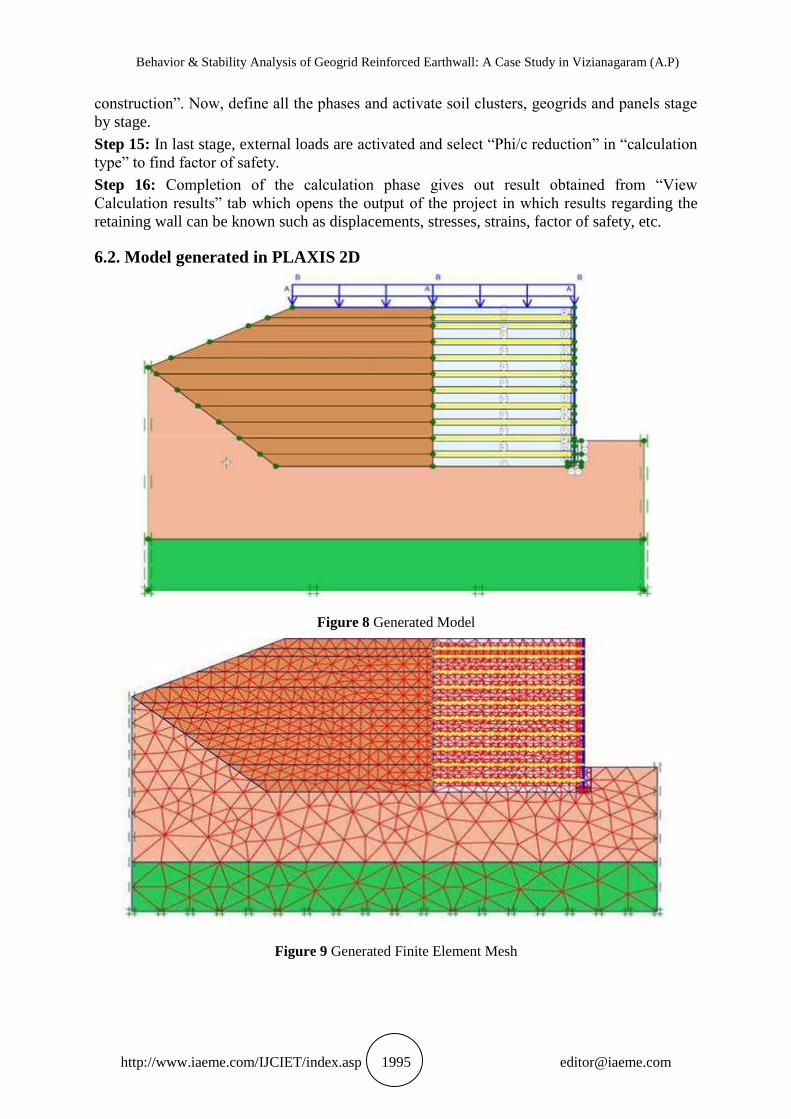
6.2. Model generated in PLAXIS 2D
Figure 8 Generated Model
Figure 9 Generated Finite Element Mesh
Abdul Asif Baig and Aditya Kumar Tiwary
http://www.iaeme.com/IJCIET/index.asp 1996 [email protected]
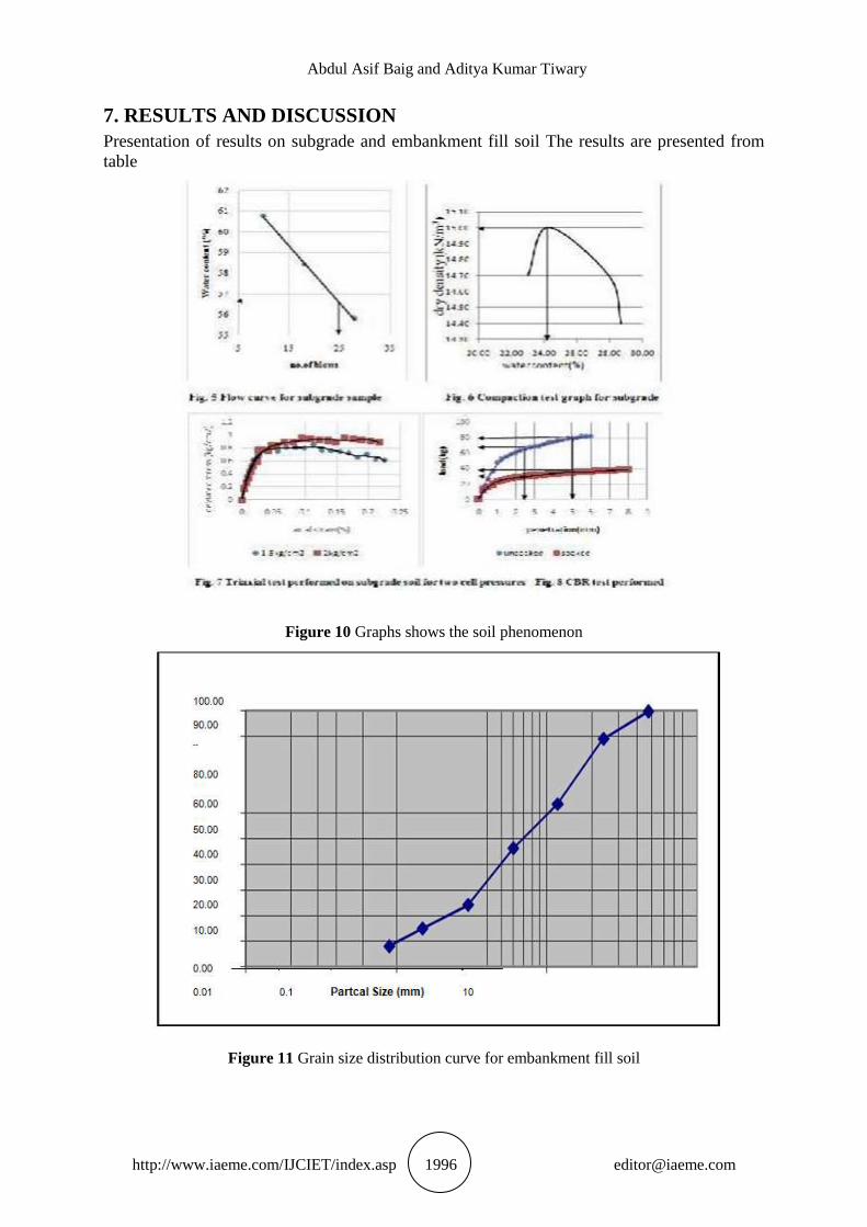
7. RESULTS AND DISCUSSION
Presentation of results on subgrade and embankment fill soil The results are presented from
table
Figure 10 Graphs shows the soil phenomenon
Figure 11 Grain size distribution curve for embankment fill soil
Behavior & Stability Analysis of Geogrid Reinforced Earthwall: A Case Study in Vizianagaram (A.P)
http://www.iaeme.com/IJCIET/index.asp 1997 [email protected]
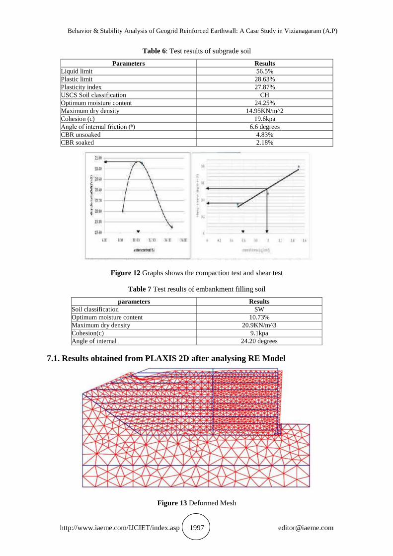
Table 6: Test results of subgrade soil
Parameters Results
Liquid limit 56.5%
Plastic limit 28.63%
Plasticity index 27.87%
USCS Soil classification CH
Optimum moisture content 24.25%
Maximum dry density 14.95KN/m^2
Cohesion (c) 19.6kpa
Angle of internal friction (ᶲ) 6.6 degrees
CBR unsoaked 4.83%
CBR soaked 2.18%
Figure 12 Graphs shows the compaction test and shear test
Table 7 Test results of embankment filling soil
parameters Results
Soil classification SW
Optimum moisture content 10.73%
Maximum dry density 20.9KN/m^3
Cohesion(c) 9.1kpa
Angle of internal 24.20 degrees
7.1. Results obtained from PLAXIS 2D after analysing RE Model
Figure 13 Deformed Mesh
Abdul Asif Baig and Aditya Kumar Tiwary
http://www.iaeme.com/IJCIET/index.asp 1998 [email protected]
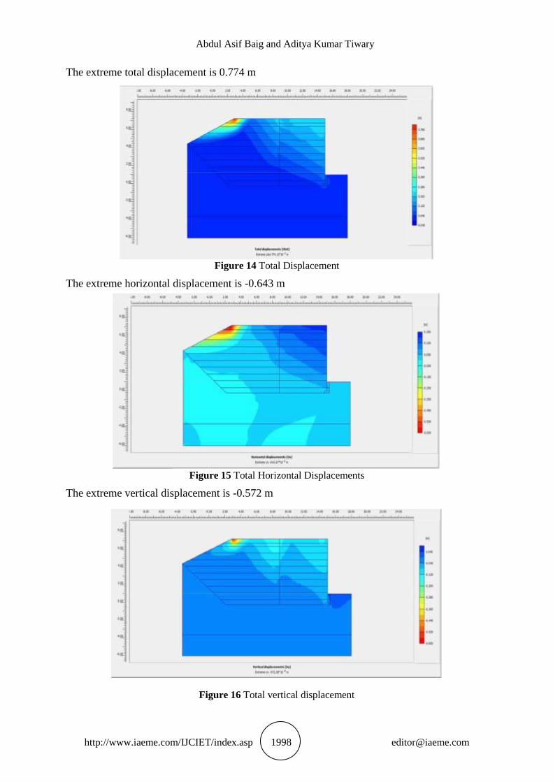
The extreme total displacement is 0.774 m
Figure 14 Total Displacement
The extreme horizontal displacement is -0.643 m
Figure 15 Total Horizontal Displacements
The extreme vertical displacement is -0.572 m
Figure 16 Total vertical displacement
Behavior & Stability Analysis of Geogrid Reinforced Earthwall: A Case Study in Vizianagaram (A.P)
http://www.iaeme.com/IJCIET/index.asp 1999 [email protected]
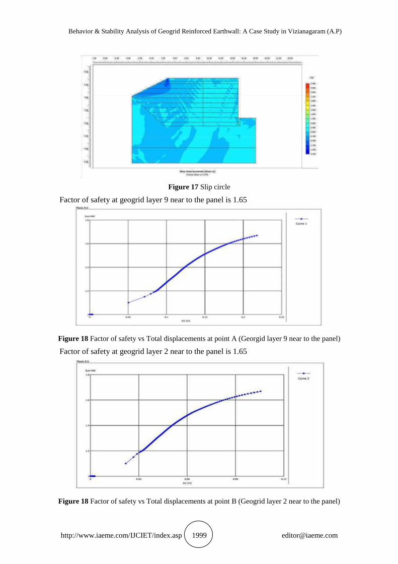
Figure 17 Slip circle
Factor of safety at geogrid layer 9 near to the panel is 1.65
Figure 18 Factor of safety vs Total displacements at point A (Georgid layer 9 near to the panel)
Factor of safety at geogrid layer 2 near to the panel is 1.65
Figure 18 Factor of safety vs Total displacements at point B (Geogrid layer 2 near to the panel)
Abdul Asif Baig and Aditya Kumar Tiwary
http://www.iaeme.com/IJCIET/index.asp 2000 [email protected]
8. CONCLUSIONS
The modeled RE wall and analysis will help in understanding failures before construction is
taken up. The contribution of reinforcement in improving stability is significant. There is an
improvement of 1.2 to 1.5 in Fs with reinforcement. Higher tensile capacities are
recommended for Higher Fs requirement.
Using PLAXIS, the final settlements of the structure after application of loading
(pavement load and vehicular load) are found out. The settlements after each stage of
construction can also be found out.
The global factor of safety of the RE Wall found out using PLAXIS is 1.65 and generally
the required factor of safety ranges between 1.3 – 1.5.
The slip circle for this geotechnical structure is also found out in this analysis using
PLAXIS.
REFERENCES
[1] Hatami, K., Bathurst. R.J. and Di Pietro. (2001) „Static response of reinforced soil
retaining walls with nonuniform reinforcement‟. The International Journal of
Geomechanics, 1(4), pp.477–506.
[2] Roy, D. and Singh, R. (2008) „Mechanically Stabilized Earth Wall Failure at Two Soft
and Sensitive Soil Sites‟. J. Perform. Constr. Facil., 22(6), pp.373-380.
[3] Stuedlein, A.W., Bailey, M., Lindquist, D., Sankey, J. and Neely, W.J. (2010) „Design and
Performance of a 46-m-High MSE Wall’. J. Geotech. Geoenviron. Eng., 136(6), pp.786-
796.
[4] Abdelouhab, A., Dias, D. and Freitag, N. (2011) „Numerical analysis of the behaviour of
mechanically stabilized earth walls reinforced with different types of strips‟. Geotextiles
and Geomembranes, 29(2), pp.116-129.
[5] Robert M. K. and George R. K. (2011) „The importance of drainage control for
mecahnically stabilized geosynthetic reinforced mechanically stabilized earth walls‟.
Journal of GeoEngineering, 6(1), pp.3-13.
[6] Hossain, M.S., Kibria, G., Khan, M.S., Hossain, J. and Taufiq, T. (2012) „Effects of
Backfill Soil on Excessive Movement of MSE Wall‟. J. Perform. Constr. Facil., 26(6),
pp.793- 802.
[7] Kibria, G., Hossain, S. and Khan, M.S. (2014) „Influence of Soil Reinforcement on
Horizontal Displacement of MSE Wall‟. Int. J. Geomech., 14(1), pp.130-141.
[8] Bilgin, O. and Mansour, E. (2014) „Effect of reinforcement type on the design
reinforcement length of mechanically stabilized earth walls‟. Engineering Structures, 59,
pp.663–673.
[9] Jewell, R.A, Reinforced soil walls analysis and behaviour. In: Jarret, P.M., McGown, A.
(Eds.), The Application of Polymeric Reinforcement in Soil Retaining Structures. Kluwer
Academic Publishers, 1987, pp. 365–408.
[10] Kaniraj, S . R . & Abdullah, H., Rotational stability of unreinforced and reinforced
embankments on soft soils. Geotextiles and Geomembranes, 13, (1994)707-726.
[11] Kaniraj, S.R. & Abdullah, H., Rotational stability of narrow crested reinforced
embankments on soft soils Geotextiles and Geomembranes, 12, (1993),599-614.
[12] Low, B.K., Stability analysis of embankments on soft ground. 1. Geotech. Engng.
Div.ASCE, 115 (2), (1989). 211-27.


![2D PLAXIS FINITE ELEMENT MODELING OF ASPHALT- … · using 2-D Plaxis FE software to analyze the unreinforced and geogrid reinforced flexible pavement structure [15]. The load is](https://img.pdfslide.net/doc/110x75/5e7a52f1f8a6b614f90b0c4c/2d-plaxis-finite-element-modeling-of-asphalt-using-2-d-plaxis-fe-software-to-analyze.jpg)