Embed Size (px)
Citation preview
BEHAVIORAL MODEL SPECIFICATION TOWARDS SIMULATION VALIDATION
USING RELATIONAL DATABASES
by
Shridhar Bendre
A Thesis Presented in Partial Fulfillmentof the Requirements for the Degree
Master of Science
ARIZONA STATE UNIVERSITY
December 2004
BEHAVIORAL MODEL SPECIFICATION TOWARDS SIMULATION VALIDATION
USING RELATIONAL DATABASES
by
Shridhar Bendre
has been approved
November 2004
APPROVED:
, Chair
Supervisory Committee
ACCEPTED:
Department Chair
Dean, Division of Graduate Studies
ABSTRACT
Many contemporary systems that are inherently large-scale and complex can be
specified using system-theoretic and object-oriented modeling concepts and principles. To
examine these systems via simulation and in particular in terms of model validation, it is
important to use model repositories. The structure and behavior of dynamical systems can
be represented as atomic models having inputs, outputs, states, and functions. Scalable
System Entity Structure Modeler with Complexity Measures (SESM/CM) offers a basis
for developing modular atomic and composite simulation models as well as non-simulatable
models. It allows simulation models to be stored, retrieved, and managed in relational
databases. The environment, however, does not provide capabilities for characterizing and
storing behavioral aspects of models or their transformation for simulation execution.
This thesis describes a design and implementation for capturing some behavioral
aspects of atomic models and the transformation of the models captured in SESM/CM into
their compatible simulatable formats in DEVSJAVA a simulation environment capable of
executing discrete-event models. The combined modeling and simulation capability offers a
process where users can develop models in the extended SESM/CM modeling environment
and validate their behavior using the DEVSJAVA simulation environment. The proposed
extensions to the SESM/CM are demonstrated using a simulated anti-virus computer net-
work model.
iii

To
My Wife, My Grandmother and My Parents
iv

ACKNOWLEDGMENTS
I wish to express sincere appreciation to my advisor Professor Hessam S. Sarjouhian,
for his time to time advice, enthusiastic support and encouragement that made the com-
pletion of this thesis possible. I would also like to thank Professors James Collofello and
Hasan Davulcu for serving on my thesis comittee.
v
TABLE OF CONTENTS
Page
LIST OF TABLES . . . . . . . . . . . . . . . . . . . . . . . . . . . . . . . . . . . . . x
LIST OF FIGURES . . . . . . . . . . . . . . . . . . . . . . . . . . . . . . . . . . . . xi
CHAPTER 1 INTRODUCTION . . . . . . . . . . . . . . . . . . . . . . . . . . . . 1
1. Simulation and Validation of Component Based Models . . . . . . . . . . . 2
1.1. Rationale for Dynamic Characterization of Atomic Model Components 3
2. Approach and Goals . . . . . . . . . . . . . . . . . . . . . . . . . . . . . . . 4
3. Contributions . . . . . . . . . . . . . . . . . . . . . . . . . . . . . . . . . . . 6
4. Thesis Overview . . . . . . . . . . . . . . . . . . . . . . . . . . . . . . . . . 8
CHAPTER 2 BACKGROUND . . . . . . . . . . . . . . . . . . . . . . . . . . . . . 10
1. Scalable System Entity Structure Modeler (SESM) . . . . . . . . . . . . . . 10
1.1. System Entity Structure (SES) Formalism . . . . . . . . . . . . . . . 10
1.2. SESM Architecture . . . . . . . . . . . . . . . . . . . . . . . . . . . . 11
1.3. SESM User Interface . . . . . . . . . . . . . . . . . . . . . . . . . . . 12
2. Databases as Model Repositories . . . . . . . . . . . . . . . . . . . . . . . . 14
3. Related Research and Environments . . . . . . . . . . . . . . . . . . . . . . 15
3.1. Modeling . . . . . . . . . . . . . . . . . . . . . . . . . . . . . . . . . 15
3.2. Simulation . . . . . . . . . . . . . . . . . . . . . . . . . . . . . . . . 17
4. Motivation . . . . . . . . . . . . . . . . . . . . . . . . . . . . . . . . . . . . 21
CHAPTER 3 SESM SYSTEM ARCHITECTURE WITH SUPPORT FOR BEHAV-
IORAL MODELING . . . . . . . . . . . . . . . . . . . . . . . . . . . . . . . . . . 23
vi
Chapter Page
1. Modeling Environment . . . . . . . . . . . . . . . . . . . . . . . . . . . . . . 24
1.1. Modeling Approach . . . . . . . . . . . . . . . . . . . . . . . . . . . 25
2. Approach for Behavioral Specification . . . . . . . . . . . . . . . . . . . . . 27
2.1. Representation of an Atomic Model . . . . . . . . . . . . . . . . . . 27
2.2. Representation of Non-Simulatable Models(NSM) . . . . . . . . . . . 30
2.3. Generation of Simulation Models . . . . . . . . . . . . . . . . . . . . 30
CHAPTER 4 BEHAVIORAL SPECIFICATION OF MODELS IN SESM . . . . . 32
1. SESM/CM Design Overview . . . . . . . . . . . . . . . . . . . . . . . . . . 32
2. Database Schema Design for Atomic Model Dynamics . . . . . . . . . . . . 34
2.1. Requirements . . . . . . . . . . . . . . . . . . . . . . . . . . . . . . . 34
2.2. ER Extensions . . . . . . . . . . . . . . . . . . . . . . . . . . . . . . 36
2.3. Entities in extended SESM E - R diagram . . . . . . . . . . . . . . . 36
2.4. Relationships in extended SESM E - R diagram . . . . . . . . . . . . 40
2.5. Extended SESM Relational Database Schema . . . . . . . . . . . . . 41
2.6. Additional constraints . . . . . . . . . . . . . . . . . . . . . . . . . . 44
2.7. Extended SESM Transactions . . . . . . . . . . . . . . . . . . . . . . 44
3. SESM Server Design Extensions . . . . . . . . . . . . . . . . . . . . . . . . 65
3.1. dbms package . . . . . . . . . . . . . . . . . . . . . . . . . . . . . . . 69
3.2. dbAccess package . . . . . . . . . . . . . . . . . . . . . . . . . . . . . 73
3.3. sesmNet package . . . . . . . . . . . . . . . . . . . . . . . . . . . . . 80
4. SESM Client Design Extensions . . . . . . . . . . . . . . . . . . . . . . . . . 81
vii
Chapter Page
CHAPTER 5 USER INTERFACE DESIGN . . . . . . . . . . . . . . . . . . . . . . 85
1. Client GUI Analysis . . . . . . . . . . . . . . . . . . . . . . . . . . . . . . . 85
1.1. Model Tree Structure Extension . . . . . . . . . . . . . . . . . . . . 85
1.2. Model Components Extension . . . . . . . . . . . . . . . . . . . . . . 87
1.3. Command Menu Extension . . . . . . . . . . . . . . . . . . . . . . . 87
2. GUI Design Extension . . . . . . . . . . . . . . . . . . . . . . . . . . . . . . 98
3. Model Transformation Design . . . . . . . . . . . . . . . . . . . . . . . . . . 99
3.1. tranformation.xml package . . . . . . . . . . . . . . . . . . . . . . . 101
3.2. tranformation.java package . . . . . . . . . . . . . . . . . . . . . . . 105
4. Re-factoring SESM Client/Server Communication . . . . . . . . . . . . . . 107
4.1. Communication Design . . . . . . . . . . . . . . . . . . . . . . . . . 109
CHAPTER 6 IMPLEMENTATION AND DEMONSTRATION . . . . . . . . . . . 112
1. Approach And Tools . . . . . . . . . . . . . . . . . . . . . . . . . . . . . . . 112
1.1. Meta-Modeling . . . . . . . . . . . . . . . . . . . . . . . . . . . . . . 112
1.2. Apache Ant . . . . . . . . . . . . . . . . . . . . . . . . . . . . . . . . 114
1.3. Implementation Details . . . . . . . . . . . . . . . . . . . . . . . . . 114
2. Anti-Virus Model Example . . . . . . . . . . . . . . . . . . . . . . . . . . . 115
2.1. Experiment Scenario . . . . . . . . . . . . . . . . . . . . . . . . . . . 116
2.2. Experiment Analysis . . . . . . . . . . . . . . . . . . . . . . . . . . . 117
3. Simulation Experiments . . . . . . . . . . . . . . . . . . . . . . . . . . . . . 121
4. Simulation Results . . . . . . . . . . . . . . . . . . . . . . . . . . . . . . . . 126
viii
Chapter Page
CHAPTER 7 CONCLUSION AND FUTURE RESEARCH . . . . . . . . . . . . . 130
1. Conclusion . . . . . . . . . . . . . . . . . . . . . . . . . . . . . . . . . . . . 130
2. Future Research . . . . . . . . . . . . . . . . . . . . . . . . . . . . . . . . . 132
2.1. Computation of Additional Metrics . . . . . . . . . . . . . . . . . . . 132
2.2. Support for storage of State Transition of Atomic Models . . . . . . 133
2.3. Transformation of State Transition to Functions . . . . . . . . . . . 133
2.4. Transformation from Simulatable Model to Database Model . . . . . 133
2.5. User Interface Enhancements . . . . . . . . . . . . . . . . . . . . . . 134
REFERENCES . . . . . . . . . . . . . . . . . . . . . . . . . . . . . . . . . . . . . . . 135
ix
LIST OF TABLES
Table Page
1. SESM Entities and Relationships . . . . . . . . . . . . . . . . . . . . . . . . 38
2. Relational Database Schema Specification for portVariable Table . . . . . . 41
3. Relational Database Schema Specification for stateVariable Table . . . . . . 42
4. Relational Database Schema Specification for NSMTemplate Table . . . . . 42
5. Input, output and state variables of models in the experiment . . . . . . . . 123
6. Simulation setup Parameter . . . . . . . . . . . . . . . . . . . . . . . . . . . 124
7. Simulation Experiments Set 1 . . . . . . . . . . . . . . . . . . . . . . . . . . 125
8. Simulation Experiments Set 2a . . . . . . . . . . . . . . . . . . . . . . . . . 125
9. Simulation Experiments Set 2b . . . . . . . . . . . . . . . . . . . . . . . . . 125
10. Simulation Experiments Set 3 . . . . . . . . . . . . . . . . . . . . . . . . . . 126
11. Simulation Experiments Set 4 . . . . . . . . . . . . . . . . . . . . . . . . . . 126
x
LIST OF FIGURES
Figure Page
1. SESM Client-Server Architecture . . . . . . . . . . . . . . . . . . . . . . . . 12
2. SESM Modeling Environment Graphical User Interface . . . . . . . . . . . . 13
3. DEVSJAVA Simulation Environment Graphical User Interface . . . . . . . 19
4. Modeling and Simulation Relations . . . . . . . . . . . . . . . . . . . . . . . 24
5. Modeling Framework . . . . . . . . . . . . . . . . . . . . . . . . . . . . . . . 25
6. SESM/CM Model Types . . . . . . . . . . . . . . . . . . . . . . . . . . . . . 26
7. Metrics Consistency and Uniformity . . . . . . . . . . . . . . . . . . . . . . 28
8. Extension of Behavioral Features of SESM . . . . . . . . . . . . . . . . . . . 29
9. Transformation of SESM models to XML and DEVSJAVA Models . . . . . 31
10. SESM System Components Overview Diagram . . . . . . . . . . . . . . . . 33
11. Extended SESM E-R Diagram . . . . . . . . . . . . . . . . . . . . . . . . . 37
12. Add Transaction Use Case Diagram . . . . . . . . . . . . . . . . . . . . . . 47
13. Delete Transaction Use Case Diagram . . . . . . . . . . . . . . . . . . . . . 51
14. Modify Transaction Use Case Diagram . . . . . . . . . . . . . . . . . . . . . 56
15. Export Transaction Use Case Diagram . . . . . . . . . . . . . . . . . . . . . 60
16. View Transactions Use Case Diagram . . . . . . . . . . . . . . . . . . . . . 62
17. SESM Server Interaction Diagram . . . . . . . . . . . . . . . . . . . . . . . 66
18. SESM Server Use Case Diagram . . . . . . . . . . . . . . . . . . . . . . . . 67
19. SESM Server Component Diagram . . . . . . . . . . . . . . . . . . . . . . . 68
20. SESM Server Sequence Diagram : Add State Variable Operation . . . . . . 82
21. SESM Client interaction diagram . . . . . . . . . . . . . . . . . . . . . . . . 84
22. Non-Simulatable Model Tree and View . . . . . . . . . . . . . . . . . . . . . 86
xi
Figure Page
23. Model Visualization Enhancements . . . . . . . . . . . . . . . . . . . . . . . 87
24. Relationship between Formalism, Database and GUI . . . . . . . . . . . . . 88
25. Model Menu for an Atomic model . . . . . . . . . . . . . . . . . . . . . . . 89
26. Model Menu for a. Adding, b. Deleting, c. Modifying Input Port Variable . 90
27. Interface for a. Adding b. Deleting c. Modifying Input Port Variable . . . . 92
28. Interface for Selecting the NSM as a Variable . . . . . . . . . . . . . . . . . 93
29. Interface for a. Modifying b. Deleting Port of a model . . . . . . . . . . . . 93
30. Interface for a. Modifying b. Deleting Component of a model . . . . . . . . 94
31. Menu for Model Export . . . . . . . . . . . . . . . . . . . . . . . . . . . . . 94
32. Menu for Source Code View . . . . . . . . . . . . . . . . . . . . . . . . . . . 95
33. Model Viewing GUI for XML Model . . . . . . . . . . . . . . . . . . . . . . 96
34. Model Viewing GUI for Java Model . . . . . . . . . . . . . . . . . . . . . . 97
35. Behavioral Information of Model . . . . . . . . . . . . . . . . . . . . . . . . 97
36. semUI.menu.subMenu Class Diagram . . . . . . . . . . . . . . . . . . . . . . 100
37. semUI.panel Class Diagram . . . . . . . . . . . . . . . . . . . . . . . . . . . 101
38. Client Sequence Diagram : Add State Variable Operation . . . . . . . . . . 102
39. transformation.xml.xmlFormatter Class Diagram . . . . . . . . . . . . . . . 103
40. transformation.xml.metaDevsXml Class Diagram . . . . . . . . . . . . . . . 104
41. transformation.java.javaFormatter Class Diagram . . . . . . . . . . . . . . . 105
42. transformation.java.metaDevsJava Class Diagram . . . . . . . . . . . . . . . 106
43. Communication between SESM components . . . . . . . . . . . . . . . . . . 108
44. Publisher-Subscriber Pattern . . . . . . . . . . . . . . . . . . . . . . . . . . 110
45. a. Processor and b. AntiVirus Model . . . . . . . . . . . . . . . . . . . . . . 116
xii
Figure Page
46. a. Atomic Models a. Processor, b. AntiVirus, c. GenrMsg, d. GenrVirus, e.
TransdSN . . . . . . . . . . . . . . . . . . . . . . . . . . . . . . . . . . . . . 119
47. WorkStation Model . . . . . . . . . . . . . . . . . . . . . . . . . . . . . . . . 120
48. SimpleNetwork Model . . . . . . . . . . . . . . . . . . . . . . . . . . . . . . 120
49. Experimental Frame Model . . . . . . . . . . . . . . . . . . . . . . . . . . . 121
50. AntiVirusExp Model . . . . . . . . . . . . . . . . . . . . . . . . . . . . . . . 122
51. Max. Avg. TA for Different Alert Messages . . . . . . . . . . . . . . . . . . 127
52. Max. Avg. TA for Different Normal Messages . . . . . . . . . . . . . . . . . 128
53. Max. Avg. TA for Different Normal Messages . . . . . . . . . . . . . . . . . 128
54. Percentage Uninfected Messages . . . . . . . . . . . . . . . . . . . . . . . . 129
55. Percentage Infected Messages . . . . . . . . . . . . . . . . . . . . . . . . . . 129
xiii
CHAPTER 1
INTRODUCTION
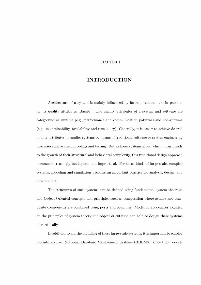
Architecture of a system is mainly influenced by its requirements and in particu-
lar its quality attributes [Bass98]. The quality attributes of a system and software are
categorized as runtime (e.g., performance and communication patterns) and non-runtime
(e.g., maintainability, availability and reusability). Generally, it is easier to achieve desired
quality attributes in smaller systems by means of traditional software or system engineering
processes such as design, coding and testing. But as these systems grow, which in turn leads
to the growth of their structural and behavioral complexity, this traditional design approach
becomes increasingly inadequate and impractical. For these kinds of large-scale, complex
systems, modeling and simulation becomes an important practice for analysis, design, and
development.
The structures of such systems can be defined using fundamental system theoretic
and Object-Oriented concepts and principles such as composition where atomic and com-
posite components are combined using ports and couplings. Modeling approaches founded
on the principles of system theory and object orientation can help to design these systems
hierarchically.
In addition to aid the modeling of these large-scale systems, it is important to employ
repositories like Relational Database Management Systems (RDBMS), since they provide
2
systematic, scalable and efficient medium for storing and accessing models [Fu02]. One of
the most important benefits of using a database repository (in addition to creating, storing,
modifying and deleting model components) is its support for reusability. Having a scalable,
reusable model repository further supports simulation and consequently model validation,
which is the key in the system development life-cycle.
1. Simulation and Validation of Component Based Models
Simulation is an imitation of the operation of a real-world process or system over
time. It involves the generation of artificial history of the system and the observation of
that history to draw inferences concerning the operating characteristics of the real system
[Bank01]. It is used to study system in a design stage, before the system is actually built.
A simulation model is developed to study the behavior of the system. Simulation modeling
can be used both as an analysis tool for predicting the effect of the changes to the existing
systems and as a design tool to predict the performance of new system under varying set
of circumstances.
In order to validate a system, the modeler needs to simulate and compare the model
and its behavior with the real or imaginary system for different sets of experimental con-
ditions. These experimental conditions include input scenarios, model initialization and
output scenarios. Input and output scenarios are mainly characterized by the input vari-
ables/output variables, their data types and their values while model initialization includes
the specification of state of the model, which is characterized by the initial values of the
state variables of the model. System state is an important aspect in characterizing the
behavior of the system, as behavior of the model is defined as the collection of the state
variables that contain all the information necessary to describe the system at any time.
3
Large-scale hierarchical models can be built by reusing persistent models. This
in turn requires the storage of the models, in both structural and behavioral form, in a
permanent repository such as database. This specification and storage of the structural (i.e.,
model name, its parts and sub-components) and behavioral (i.e. input/ output variables
and states) aspects of the model allows the modeler to achieve the simulation, analysis and
validation of the model.
1.1. Rationale for Dynamic Characterization of Atomic Model Compo-
nents. System theory distinguishes between the system structure and behavior, where
structure is the inner constitution of the system while the behavior is its outer manifes-
tation. It offers capabilities to model structural and behavioral dynamical systems using
the concepts of atomic and composite components [Wym93, Zei00]. Atomic models are the
basic models which cannot be decomposed into other models while the composite models
are models that can be composed of other atomic and/or composite models. The structure
of atomic model is represented in terms of name, input ports and output ports while that
of coupled model is defined in terms of name, input ports, output ports and couplings.
The external behavior of an atomic model includes the relationship between its input and
its output, while the internal behavior includes the state, state transition, functions and
output mechanisms. Similarly, the external behavior of a composite model is visible via
its input and output ports and couplings. The internal behavior of a composite model is
the resultant of the behaviors of its sub-components which are connected via couplings.
Hence, composite models primarily focus on the constitution of sub-components and their
communication with each other as well as with the other sub-models of their parent model,
while the actual behavior of the system is determined by the resultant of the behaviors of
4
the atomic models in the system.
As mentioned above, specification of the behavioral aspects of the system is required
to achieve the model simulation and validation. These behavioral aspects of the system can
be expressed in terms of the dynamic characteristics of an atomic model such as specification
of inputs arrived at input ports, outputs sent to output ports and states of the system. This
essentially involves specification and storage of input variables, output variables and state
variables, variable types and variable values.
Once a model is built in terms of both structure and behavior, it is important to
verify whether the model behavior is correct or not. This involves the observation of the
behavior of the model (e.g., state changes) in response to different input regimes and initial
conditions. For this, model needs to be simulated with an appropriate simulation engine.
This requires transformation of the model specification in to simulation compatible format.
Once the modeler has that format, the model can be simulated under different scenarios
and consequently validated.
2. Approach and Goals
The primary goal of this thesis is to specify the behavioral aspects of atomic model
to support creation of simulation models and their validation. This involves the design
and development of dynamic characteristics of atomic model. This includes representation
of input variables, output variables and state variables in the relational databases. It
also involves the design and development of the user interface to support the capturing of
these behavioral aspects of atomic model and development of a mechanism to store them
in a database. Furthermore, it is important to support representation and storage of non-
simulatable models (NSM), which are similar to complex data structures like list, bag or set.
5
These non-simulatable models can be used as components of simulatable atomic models.
Once the model is specified, it needs to be transformed into a simulation compatible format
to achieve simulation in the simulation environment.
In this research, we are using and extending the Scalable entity Structure Modeler
(SESM/CM) [Sar02, Fu02, Smo03], which is a modeling environment suitable for developing
modular hierarchical systems. Current version of SESM/CM provides a modeling engine
with a graphical user interface for creating, modifying, storing and reusing the structural
aspects of the atomic and coupled models. These structural features involve name (identity)
of the model, input/output ports (interface), couplings and modular hierarchical structures
(specialization and aggregation relationships). It provides a relational database for storing
and managing structure of atomic and coupled models and is suitable for development of
large-scale models.
SESM/CM offers a basis for modeling behavioral aspect of atomic models. It does
not, however, provide capabilities for characterizing behavior of atomic models and non-
simulatable models, which involves the specification of how it can process inputs, transition
through different states and generate outputs. Furthermore, since SESM/CM is a modeling
environment, it does not provide facilities for simulation. Therefore, to support simulation,
the atomic and composite models in SESM/CM must be transformed to their simulation
compatible formats.
This research, therefore, focuses on extending the SESM/CM environment such
that it can support some parts of behavior modeling of atomic models and inclusion of
non-simulatable models. To enable model to simulation transformation, a modeling-to-
simulation approach is designed and developed to support simulation of models partially
described in SESM/CM in DEVSJAVA environment, where DEVJAVA is a simulation
6
environment capable of executing hierarchical models specified in Discrete-Event System
Specification. This combined modeling and simulation capabilities offer a process where
users can develop models, simulate their behavior and carry out model validation, while
relying on model storage and reuse in a systematic fashion.
The secondary goal of this research is to improve the performance and usability of
the SESM/CM by providing an alternate design of data transfer mechanism between the
SESM/CM client and the database.
The high-level objectives of this thesis are mentioned below. These objectives
collectively required analysis, design, implementation, testing and demonstration of the
SESM/CM modeling environment as follows:
• Support capturing, storing, and retrieving dynamic characteristics of an atomic model
components,
• Develop mappings for converting atomic and coupled models in RDBMS to those that
can be simulated in DEVSJAVA, and
• Use an efficient communication model in order to ensure acceptable performance and
availability for large-scale models.
3. Contributions
The primary contributions of this thesis are in line with the objectives of the thesis.
They are
• development of designs for characterizing the behavioral aspects of atomic models.
It involves devising schemes for representation of input variables, output variables
7
and state variables in a modeling environment, in simulation compatible models and
in database. This approach also supports storage of Non-Simulatable models and
their relationships with Simulatable models. To support these features, the data-
base schemas are extended in order to enable combined use of simulatable and non-
simulatable models within the SESM modeling framework,
• development of detailed design for transforming simulatable models captured in SESM
to appropriate forms (such as XML and JAVA) such that they can be executed in the
simulation environment like DEVSJAVA. This involves the design and development
of two new modules each for the transformation of graphical models to XML or Java
models,
• implementation of extended features of SESM to support efficient modeling behavior of
dynamic systems. It involves addition of new capabilities to SESMs different modules
like server, client, database and network environment without changing the overall
architecture of modeling environment. This also includes testing and validation of
the extended functionality of the prototype SESM environment and its use with the
DEVSJAVA environment using example from the domain of computer networks and
viruses, And
• extension of an architecture for SESM to support the local copy of data for each client
using observer design pattern to achieve better performance and availability and to
support distributed and collaborative modeling using SESM.
8
4. Thesis Overview
This thesis is organized as follows. In this chapter (chapter 1) , we have discussed
the rationale and importance of the specification and storage dynamic characterization
(behavioral specification) of models in addition to structural specification. We have also
discussed the need for simulation and validation of these models.
Chapter 2 gives an overview of background and research related to the thesis topic.
It involves the detailed description of SESM/CM modeling engine and its constituents
architecture and design which is the foundation of this research. It also describes other
approaches for modeling and simulation of component-based systems.
Chapter 3 presents basic concepts of behavioral modeling and the extension of the
SESM/CM architecture to support some aspects of the dynamic characterization of atomic
models. It describes the importance of Non-Simulatable Models (NSM) and their utility. It
also summarizes the mechanism for the generation of simulatable models by transforming
them into XML and Java models.
Chapter 4 discloses the detailed software analysis and design extended to support
behavioral modeling in SESM modeling engine. It involves extensions to server, client and
database modules. This section renders UML (Unified Modeling Language) as well as ER
(Entity-Relationship) diagrams. It provides the detailed design for the new transformation
modules. Finally, it suggests an alternate design for an efficient communication between
client and server.
Chapter 5 exhibits the user interface design which involves extensions of the three
GUI areas namely, model tree structure, model components and command menu. It involves
the redesign of the model menu. It also explains the design for the transformation of models
9
stored in the database into the simulation compatible models.
Chapter 6 gives implementation details of the new and extended features discussed
and designed in the previous chapters. It discusses the technology used for software devel-
opment like Java, JDBC and XML. It also demonstrates an example of Anti-Virus Model,
which includes building of new models exhibiting the new features introduced in this thesis.
It also explains the experiments conducted on this model and their simulation results.
Chapter 7 discusses future research and conclusions.
CHAPTER 2
BACKGROUND
1. Scalable System Entity Structure Modeler (SESM)
This research is primarily concerned with the SESM [Smo03, Fu02] modeling en-
vironment. It deals with the usage and extension of this environment to incorporate and
demonstrate the various aspects of this thesis, mentioned in the thesis objectives section.
1.1. System Entity Structure (SES) Formalism. System Entity Structure
(SES) formalism [Zei84] is a structural knowledge representation scheme that systemati-
cally organizes a family of possible structures of the system. The fundamental object of
the SES formalism is an entity, also known as model. It represents a physical object in
the real world and has identification, attached variables and a range set. This range set is
an enumeration of values that the variable can assume. This entity can be of two types,
atomic entity and composite entity. Atomic entities cannot be broken down into sub entities,
while Composite entities are broken down into other entities, either atomic or composite.
SES provides three types of relationships among the entities, namely aspect (alternative
representation of the system or model), decomposition (Part-Whole relationship) and spe-
cialization (Parent-Child relationship). These relationships are useful to build the models
hierarchy.
11
This model hierarchy enforces certain axioms [Zei00], which include
• Alternating Entity Aspect/Specialization: Each node has a mode which is either entity
or specialization
• Uniformity: Any two nodes with the same names have identical attached variable
types and isomorphic sub-trees.
• Strict Hierarchy: No label appears more than once down any path of the tree.
• Valid Brothers: No two brothers have same label
• Attached Variables: No two variable types attached to the same item have same name.
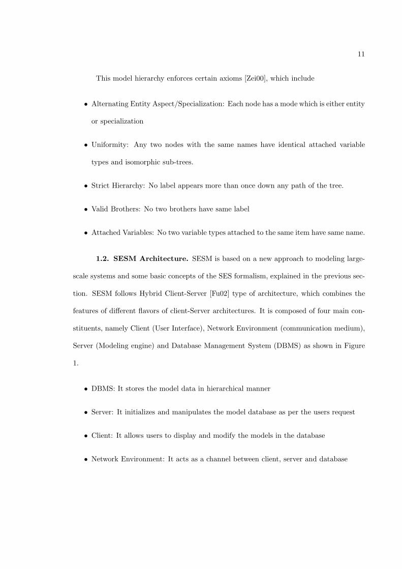
1.2. SESM Architecture. SESM is based on a new approach to modeling large-
scale systems and some basic concepts of the SES formalism, explained in the previous sec-
tion. SESM follows Hybrid Client-Server [Fu02] type of architecture, which combines the
features of different flavors of client-Server architectures. It is composed of four main con-
stituents, namely Client (User Interface), Network Environment (communication medium),
Server (Modeling engine) and Database Management System (DBMS) as shown in Figure
1.
• DBMS: It stores the model data in hierarchical manner
• Server: It initializes and manipulates the model database as per the users request
• Client: It allows users to display and modify the models in the database
• Network Environment: It acts as a channel between client, server and database
12
Client
Network environment
Server DBMS
Read & Write
Read Only
Figure 1. SESM Client-Server Architecture
Client and Server independently initialize and maintain their connectivity with the
database. Client has “Read-only” access which means it can independently read the model
data from the database while for writing to the database, it has to communicate via the
server, which writes the data to the database. The server has both “Read and write” access
which means it can read and write data from and to the database. In this way, SESM
allows multiple readers (i.e., multiple clients and server) of the data but only single writer
(i.e., server) and hence it provides the consistency of the model data in the database. In
this architecture, client and server are loosely coupled and hence result in better design and
implementation. It produces less network traffic between client and server and gives better
scalability by shifting the large number of queries from server to the database.
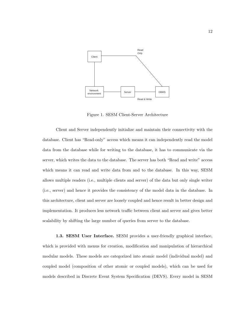
1.3. SESM User Interface. SESM provides a user-friendly graphical interface,
which is provided with menus for creation, modification and manipulation of hierarchical
modular models. These models are categorized into atomic model (individual model) and
coupled model (composition of other atomic or coupled models), which can be used for
models described in Discrete Event System Specification (DEVS). Every model in SESM
13
Menu Bar
Tool Bar
Model Tree
Model Viewer
Model Menu
Model Tree Views
Menu Bar
Tool Bar
Model Tree
Model Viewer
Model Menu
Model Tree Views
Figure 2. SESM Modeling Environment Graphical User Interface
is considered as an object with input and output ports which form a well-defined interface
for the interactions with other models. The sub-components are connected to each other
with internal couplings while they are connected to the parent coupled model with external
input couplings and external output couplings. Hence with the use of port, couplings and
components, SESM allows capturing the “structural” representation of hierarchical models
as defined by DEVS.
As shown in Figure 2, user can create atomic and coupled component-based models
using ports and couplings [Wym93]. SESM graphical interface provides a menu bar with
menus, “Operations” and “Database”. The Operations menu offers options to “Create
14
Template Model”, “Create Instance Template Model” and “Create Instance Model”. The
Database menu offers an option to “Initialize Database” which essentially erases the entire
data (i.e., all the models) in the database. The model Tree displays the tree view of
hierarchical models stored in the database. There are three views of these models namely,
Template Model (TM), Instance Template Model (ITM) and Instance Model (IM). Model
Viewer area displays a specific model that is currently selected in the model tree. It shows
the model with model name, ports and couplings (in case of coupled models). Model
menu gives functionalities to manipulate the model displayed in the model viewer. Toolbar
provides the features for printing, saving as well as refreshing the models on the graphical
user interface.
2. Databases as Model Repositories
Large scale systems are increasingly developed by using model-based analysis and
design techniques. As these systems grow in size and complexity, a methodical approach is
required to have a repository, which can provide the capabilities like usability, scalability,
modifiability and storage of models. Relational database is an appropriate option for these
repositories as it provides functionalities like creation, modification, storage and most im-
portantly reuse of the stored models. It offers modular hierarchical representation of the
models in the database by providing the relationships like composition (Part-Of relation-
ship) and specialization (IS-A relationship). It allows user to enforce the constraints on the
models stored in the relations set. It also provides scalability and flexibility by providing
the data independence where data is decoupled from the application development. And
finally, it uses Structured Query Language (SQL) as an interaction medium, a standard
language for the relational databases; which is important for application portability.
15
The rationale [Fu02] behind the use of relational database is that the relational model
supports the formal specification of the logical relationships such as those in three views and
SES. The simplicity of the relational model also allows the DBMS vendors to optimize the
management systems for performance and scalability. Compared to relational databases,
the third generation databases like OODB and ORDB are still constantly evolving. Further-
more, both OODBMS and ORDBMS lack the full support for the current standards. The
lack of standardization means less support for developing SESM, and it makes the SESM
vendor specific. As a result, after comparing the three types of the database technologies,
the relational database was selected to be an appropriate medium of repository for SESM.
Implementation of SESM uses MS-Access relational database.
3. Related Research and Environments
3.1. Modeling. An alternative approach for systematically representing models is
via the Unified Modeling Language (UML) [Boo94, Boo99].
3.1.1. UML. UML is a graphical language used for visualizing, specifying, construct-
ing and documenting the artifacts of a software intensive system [Boo99]. It provides the
modeler a standard way to specify system blueprints, covering conceptual things like busi-
ness processes and system function as well as concrete things like classes which may be
written in specific programming language and database schemas. It is appropriate for mod-
eling systems ranging from enterprise information systems to distributed web-applications
to real-time embedded systems.
UML and SESM are similar in how they represent a systems structure (i.e., com-
ponent and relationships) as both of them support “is-a” and “part-of” relationships. But
they are different as UML is intended for the object-oriented software engineering [Fow99]
16
while the SESM is targeted for representing simulation models and their structures. UML
supports access rights of an attribute (e.g., public or private) while SESM supports com-
munication between the models using ports and couplings. Though UML supports the
behavior of the model in terms of methods specification, tools such as Rational Rose do
not offer capabilities to fully specify behavior of the model - i.e., with UML, a modeler can
declare the methods to define the behavior and specify a state-chart to show state transi-
tions, but the details of the methods has to be done using IDEs. In UML, the behavior
of the composed model is a resultant of its own behavior and the behavior of all of its
sub-components, whereas in SESM models the behavior of the composed model is just the
resultant of the behavior of its sub-components as the composed model doesn’t have its
own behavior. Another major difference is in UML, the models are stored in a flat file,
whereas in SESM, models are stored in a relational database, which offers scalability and
better reusability.
UML model such as class diagram is typically not refined enough to provide all the
relevant aspects of the specification. There is a need to describe the additional constraints
of the object of the model. Object Constraint Language (OCL) is used as a formal language
for the specification of constraint for the UML models. UML modeler can use OCL for ap-
plication specific constraints to specify invariants on classes and types in the class model,
type variants for stereotypes, pre-conditions, post-conditions and guard conditions on op-
erations and methods. OCL is a pure expression language where expressions are evaluated
to check particular constraints. But it is not a programming language; hence one cannot
write program logic or flow control using OCL and hence cannot change anything in the
model. In short, OCL can be used to express constraint that cannot be captured in UML
but it cannot be used for specifying or altering the state of the model.
17
A real-time extension of UML is called UML-RT, which supports structural modeling
of a system similar to SESM. UML-RT is also based on system concepts and methods. The
semantics of the ports and connections in UML-RT are different than the semantics of the
couplings and ports in SESM, when applied to discrete-event system specification. One of
the essential differences between UML-RT and a combination of SESM and DEVSJAVA is
that the latter has well-defined simulation engine. In contrast, simulation using UML-RT
is limited since it provides execution which requires users to specify simulation protocols.
3.2. Simulation. Simulation involves designing the model of a system and carrying
out experiments on it as it progresses through time. Simulation is an important activity
since it allows the modeler to experiment that might be hard or cannot be analytically
predicted. It can give a valuable insight into the system and into the relative importance
of the different choices about the design of the system. It allows compression of time and
prediction of the behavior of the system. There are different types of simulators available.
This thesis briefly describes DEVSJAVA and Extend; both of which support modeling
discrete systems.
3.2.1. DEVSJAVA. This research uses DEVSJAVA [acims04, Sar03, Sing04], which
is a modeling and simulation environment, supporting a hierarchical, modular DEVS sim-
ulation models. It supports the basic and advanced capabilities for observing behavior of
models in logical and (near) real-time. DEVS models are based on DEVS formalism, which
can be mathematically expressed [Zei00, Zei03] as,
M =< X ,S ,Y , δint , δext , δcon , λ, ta >
Where
X is the set of inputs
18
X : {(p, v)|p ∈ InPorts, v ∈ X}
S is a set of states
Y is the set of outputs
Y : {(p, v)|p ∈ OutPorts, v ∈ Y}
δint : S− > S is the internal transition function
δext : Q × X b− > S is the external transition function, where
Q = {(s, e)|s ∈ S, 0 ≤ e ≤ ta(s)} is the total state set
e is the time elapsed since last transition
δcon : Q × X b− > S is the confluent transition function
λ : S− > Y b is the output function
ta : S− > R+
0 ,∞is the time advance function
This modeling approach supports discrete-event (and thus discrete-time) dynam-
ics as well as continuous dynamics [Kof03]. DEVSJAVA is an implementation of DEVS
formalism in Java, which allows the modeler to specify and execute (i.e., simulate) the
models. As mentioned earlier, these models are of two types, atomic models and coupled
models. Atomic models are the basic models from which the larger models are built. They
19
Menu Bar
Model Tree View
Model State View
Input Buttons
Simulation Interactive
Buttons
Simulation State View
Tracking options States Inputs Outputs
Figure 3. DEVSJAVA Simulation Environment Graphical User Interface
are defined to have time base, inputs, states, outputs and functions for determining next
states and outputs given current states and inputs. The coupled models are composed of
the other atomic and/or coupled models connected together by couplings in hierarchical
manner. Both of these models are supported with input and output ports to facilitate the
communication with the other models and the outside world.
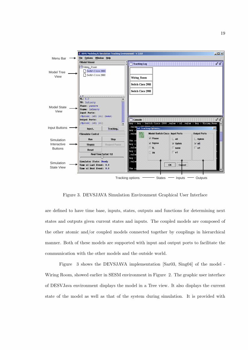
Figure 3 shows the DEVSJAVA implementation [Sar03, Sing04] of the model -
Wiring Room, showed earlier in SESM environment in Figure 2. The graphic user interface
of DESVJava environment displays the model in a Tree view. It also displays the current
state of the model as well as that of the system during simulation. It is provided with
20
different buttons
• Inject: It is used to inject the inputs in the model during the setup of an experiment
• Tracking: It gives an interactive dialog shown in the figure, which can be used to select
the input, output or state variables that need to be tracked during the simulation.
• Step: It runs the simulation of the model step-by-step and allows user to see the
inputs and outputs generated as well as the state changes for the models at a step
level.
• Run: It runs the whole simulation and produces the entire results of the simulation
at the end of the simulation
• Reset: It restarts the simulation process and also resets the system clock to zero.
3.2.2. Extend. Extend [Ext00] is offered by Imagine That, Inc. Extend combines the
block diagram approach to model building and an authoring environment for creating new
blocks. It is based on process oriented world view and capable of continuous, discrete event
and combined modeling. Most important parts of Extend model are the blocks, libraries
where the blocks are stored, the dialogs associated with each block and the connectors.
Elemental blocks include generator, queue, activity, resource pool and exit. Activity entities,
called items, are created at generator blocks and move from block to block with the help of
connectors. Modelers can build models by placing and connecting blocks and filling in the
parameters. Collections of these blocks are grouped together to form a hierarchy which is
essentially a library.
Extend stores the model data in the form of text files which can be opened, closed,
read and edited using Extend as well as any other word processor. It comes with a compiled
21
C-like simulation programming language called ModL. It contains simulation support as well
as support for custom user interface and message communication. It is also provided with
a statistics library which supports the collection, analysis and plotting of simulation data.
This modeling environment is similar to DEVSJAVA and others such as MATLAB that do
not support some important capabilities such as multi-view and scalable persistence.
4. Motivation
All the approaches of modeling and simulation described above have distinguishable
features which support structural and/or behavioral aspects for modeling, simulation or
storage. DEVSJAVA offers modeling and simulation interface but the model creation in
DEVSJAVA is limited to writing code in Java language which requires low level program-
ming expertise in Java. Extend supports easy graphical model creation as well as structural
and behavioral model definition, but it stores the models in flat files and hence cannot pro-
vide expected scalability. UML is a widely accepted technique for modeling but it doesn’t
support multiple views as well as the simulation of the models. SESM is a modeling envi-
ronment which stores the models in the relational database and hence achieves hierarchical
and scalable model construction. But it needs to be extended to support the storage of the
behavioral aspects of the models.
Therefore, there is a need of an environment that
• facilitates easy creation of models from both structural and behavioral perspective
without any dependency on programming
• supports storage of models in the repository

22
• aids simulation of the models
CHAPTER 3
SESM SYSTEM ARCHITECTURE WITH SUPPORT FOR
BEHAVIORAL MODELING
Modeling and simulation of systems has become de-facto standard in the analysis
and development of large-scale systems. It is important to employ modeling and simulation
methods that can support model specification and simulation execution. Model Specifi-
cation in turn involves the structural and behavioral specification of the model, while the
simulation execution involves the transformation of these specified models into their simu-
latable format. In particular, separating the real (or imagined) system, specification models,
and simulatable models are important for model validation and simulation verification.
Many kinds of models maybe defined using composition and specialization concepts.
These models, in general, are referred to as base and lumped models. The former refers
to a model that is most closely represents a system (i.e., the real system and base model
are homomorphic to one another). The later refers to a model that is an abstraction of the
base model. A lumped model, therefore, can represent the real system via a base model or
directly the system itself. The base and lumped models are homomorphic to one another.
24
uni - simulator uni - simulator
Parallel Simulator Parallel
Simulator parallel/distributed
simulator parallel/distributed
simulator
component
modeling relation
simulation relation
Model A
Model B
component
sub - comp
component
sub - comp
sub - com
sub - comp
Real or imagined system
Real or imagined system
uni - simulator uni - simulator
Parallel Simulator Parallel
Simulator parallel/distributed
simulator parallel/distributed
simulator
component
modeling relation
simulation relation
Model A
Model B
component
sub - comp
component
sub - comp
sub - com
sub - comp
sub - comp
component
sub - comp
sub - com
sub - comp
Real or imagined system
Real or imagined system
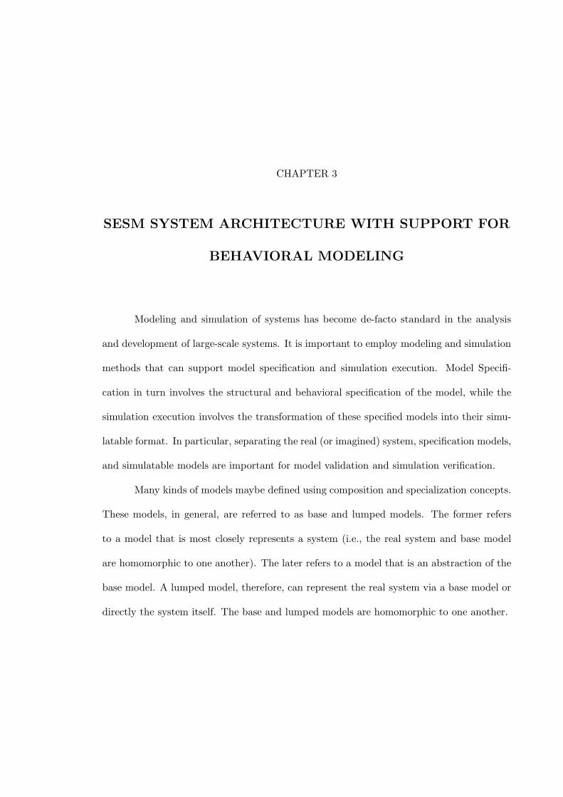
Figure 4. Modeling and Simulation Relations
1. Modeling Environment
Specification models are developed during the modeling phase. A modeling engine
supports specification of models using a modeling language. The ability to support spec-
ification of large-scale models plays a key role in defining the modeling and simulation
relations.
A modeling environment, therefore, needs to support modelers to specify their mod-
els in an iterative and incremental fashion. In other words, impediments in validation and
verification can be better overcome using a modeling environment that can support not
only representation of a family of models, but also with support for handling scalability
of models and therefore their relationships. The scalability is important in managing the
relationships among models developed within the modeling phase. Furthermore, scalability
also plays a key role in the modeling and simulation relations as shown in Figure 4.
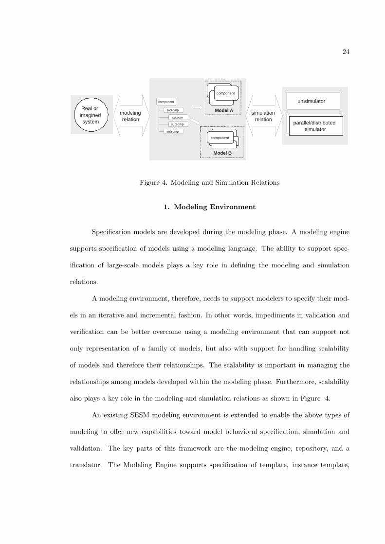
An existing SESM modeling environment is extended to enable the above types of
modeling to offer new capabilities toward model behavioral specification, simulation and
validation. The key parts of this framework are the modeling engine, repository, and a
translator. The Modeling Engine supports specification of template, instance template,
25
Modeling Engine
Simulation Engine Translator
Repository Model
Specifications Simulation Code
Modeling Engine
Simulation Engine Translator
Repository Model
Specifications Simulation Code
Modeling Engine
Simulation Engine Translator
Repository Model
Specifications Simulation Code
Figure 5. Modeling Framework
and instance models. The Repository contains the models in a relational database. The
Translator maps instance models into simulation code.
This modeling environment allows modeling a family of models that may be closely
related, yet are serve different purposes. For complex, using alternative decompositions, two
models can represent two different aspects of a model. Models can be mutually exclusive if
they do not share model components. Similarly, using specialization, a system may have two
or more aspects or resolutions. Handling of multi-aspect and multi-resolution are important
in modeling of heterogeneous systems.
1.1. Modeling Approach. The proposed model framework shown in Figure 5
supports modeling of a system using three complementary types of models called Template
Model, Instance Template Model, and Instance Model. The basic approach is component-
based modeling where a system is viewed as a collection of components which are composed
using input and output ports and couplings.
A template model specifies atomic and composite models as components with in-
26
Template Model
Two - Level Structure
Instance Template
Model
Multi - Level Structure
Instance Model
Multi - Level Structure
Template Model
Two - Level Structure
Instance Template
Model
Multi - Level Structure
Instance Model
Multi - Level Structure
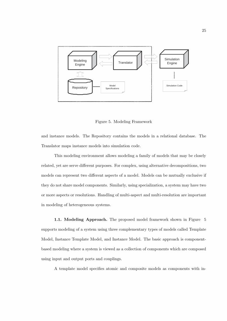
Figure 6. SESM/CM Model Types
put and output ports and values. An atomic template model specification contains state
variables and a name. The components of each of these three model types are restricted
to have the same type - a template model can have other template models and not models
of instance template or instance models. A composite template model specification has
couplings and a name. Composite template models are restricted to have atomic and/or
composite template models as children. Furthermore, the name assigned to atomic and
composite models must be unique such that any composite model can be uniquely identi-
fied within its hierarchical decomposition. A composite template model is defined to have
a hierarchy of length two.
An instance template model is the same as a template model. This type of model is
defined to have a finite hierarchy of length greater than two. Furthermore, this model does
not specify multiplicity of a model component within any composite model - a model can
have one to a finite number of copies of the same instance template model. An instance
model is an instantiation of an instance template model where the multiplicity of model
instances is specified.
27
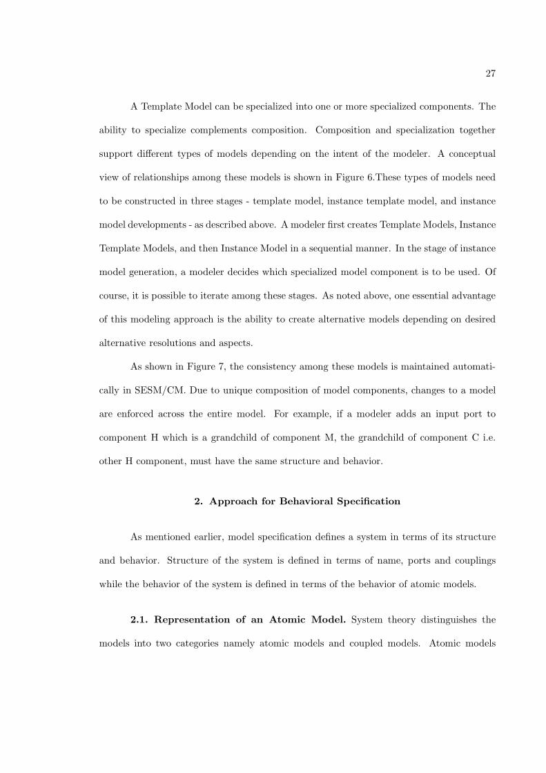
A Template Model can be specialized into one or more specialized components. The
ability to specialize complements composition. Composition and specialization together
support different types of models depending on the intent of the modeler. A conceptual
view of relationships among these models is shown in Figure 6.These types of models need
to be constructed in three stages - template model, instance template model, and instance
model developments - as described above. A modeler first creates Template Models, Instance
Template Models, and then Instance Model in a sequential manner. In the stage of instance
model generation, a modeler decides which specialized model component is to be used. Of
course, it is possible to iterate among these stages. As noted above, one essential advantage
of this modeling approach is the ability to create alternative models depending on desired
alternative resolutions and aspects.
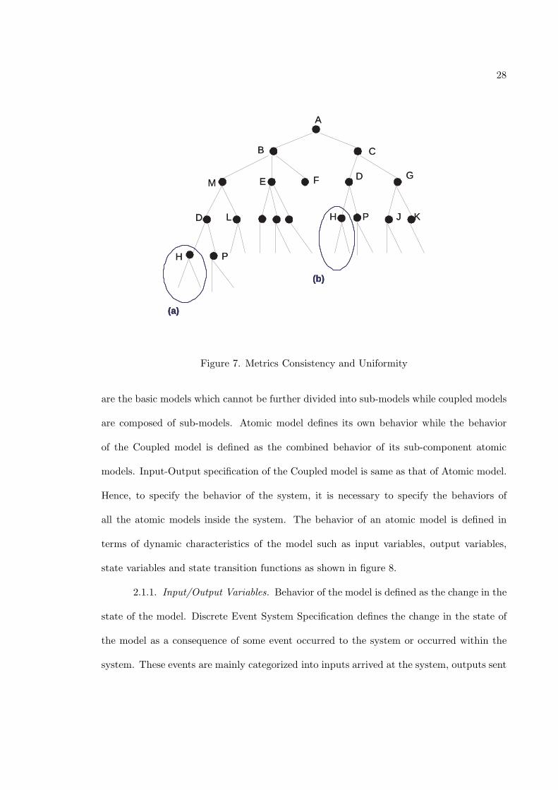
As shown in Figure 7, the consistency among these models is maintained automati-
cally in SESM/CM. Due to unique composition of model components, changes to a model
are enforced across the entire model. For example, if a modeler adds an input port to
component H which is a grandchild of component M, the grandchild of component C i.e.
other H component, must have the same structure and behavior.
2. Approach for Behavioral Specification
As mentioned earlier, model specification defines a system in terms of its structure
and behavior. Structure of the system is defined in terms of name, ports and couplings
while the behavior of the system is defined in terms of the behavior of atomic models.
2.1. Representation of an Atomic Model. System theory distinguishes the
models into two categories namely atomic models and coupled models. Atomic models
28
(a)
(b)
A
C B
F D G E M
H P K J D L
P H
(a)
(b)
(a)
(b)
A
C B
F D G E M
H P K J D L
P H
Figure 7. Metrics Consistency and Uniformity
are the basic models which cannot be further divided into sub-models while coupled models
are composed of sub-models. Atomic model defines its own behavior while the behavior
of the Coupled model is defined as the combined behavior of its sub-component atomic
models. Input-Output specification of the Coupled model is same as that of Atomic model.
Hence, to specify the behavior of the system, it is necessary to specify the behaviors of
all the atomic models inside the system. The behavior of an atomic model is defined in
terms of dynamic characteristics of the model such as input variables, output variables,
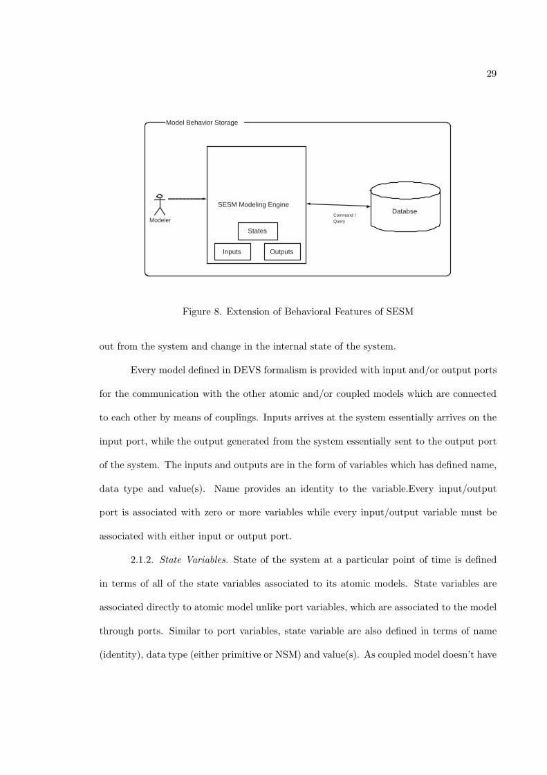
state variables and state transition functions as shown in figure 8.
2.1.1. Input/Output Variables. Behavior of the model is defined as the change in the
state of the model. Discrete Event System Specification defines the change in the state of
the model as a consequence of some event occurred to the system or occurred within the
system. These events are mainly categorized into inputs arrived at the system, outputs sent
29
Model Behavior Storage
Databse Modeler
Command / Query
SESM Modeling Engine
Inputs Outputs
States
Figure 8. Extension of Behavioral Features of SESM
out from the system and change in the internal state of the system.
Every model defined in DEVS formalism is provided with input and/or output ports
for the communication with the other atomic and/or coupled models which are connected
to each other by means of couplings. Inputs arrives at the system essentially arrives on the
input port, while the output generated from the system essentially sent to the output port
of the system. The inputs and outputs are in the form of variables which has defined name,
data type and value(s). Name provides an identity to the variable.Every input/output
port is associated with zero or more variables while every input/output variable must be
associated with either input or output port.
2.1.2. State Variables. State of the system at a particular point of time is defined
in terms of all of the state variables associated to its atomic models. State variables are
associated directly to atomic model unlike port variables, which are associated to the model
through ports. Similar to port variables, state variable are also defined in terms of name
(identity), data type (either primitive or NSM) and value(s). As coupled model doesn’t have
30
a defined state, there are no state variables associated with it, while each atomic model is
associated with zero or more state variables. Values of all the state variables collectively
define the state of the model.
2.2. Representation of Non-Simulatable Models(NSM). In addition to these
models, it is also important to represent non-simulatable models which may be used as part
of atomic models. These models are distinct compared with the template models since they
do not have input/output ports. Such non-atomic models are referred to as non-simulatable
since their behavior is not time-dependent. Examples of these models are object-based user
defined complex data structures such as a list or a queue, which are useful to hold multiple
values.
As stated above, input-output-state variables are defined in terms of name, data
type and value(s). The data type of these variable is an important aspect. This data type
can be divided into two types; either primitive data type (supported by the programming
language such as integer, character, string, etc) or non-simulatable (NSM) models.
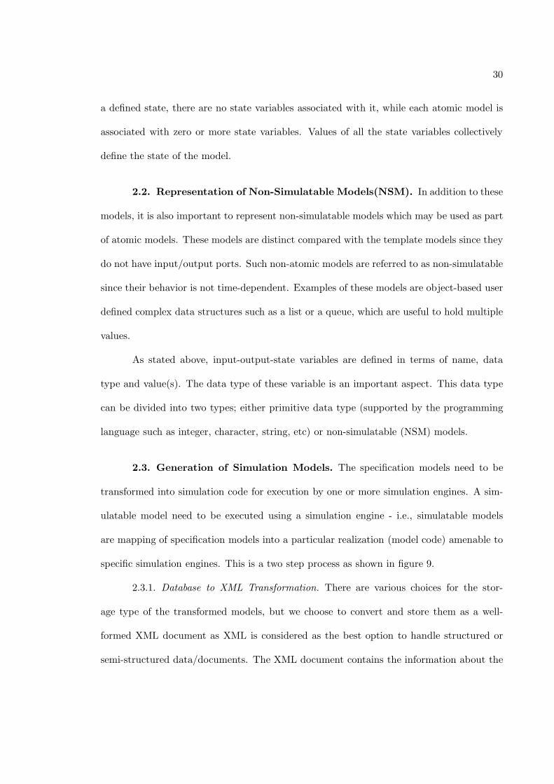
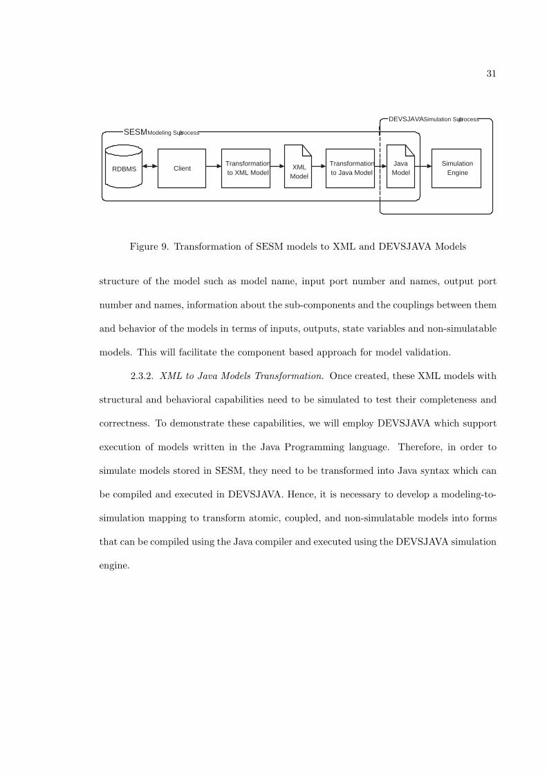
2.3. Generation of Simulation Models. The specification models need to be
transformed into simulation code for execution by one or more simulation engines. A sim-
ulatable model need to be executed using a simulation engine - i.e., simulatable models
are mapping of specification models into a particular realization (model code) amenable to
specific simulation engines. This is a two step process as shown in figure 9.
2.3.1. Database to XML Transformation. There are various choices for the stor-
age type of the transformed models, but we choose to convert and store them as a well-
formed XML document as XML is considered as the best option to handle structured or
semi-structured data/documents. The XML document contains the information about the
31
DEVSJAVA : Simulation Sub - process
SESM : Modeling Sub - process
Client Transformation to XML Model
XML Model
Transformation to Java Model
Java Model
Simulation Engine RDBMS
Figure 9. Transformation of SESM models to XML and DEVSJAVA Models
structure of the model such as model name, input port number and names, output port
number and names, information about the sub-components and the couplings between them
and behavior of the models in terms of inputs, outputs, state variables and non-simulatable
models. This will facilitate the component based approach for model validation.
2.3.2. XML to Java Models Transformation. Once created, these XML models with
structural and behavioral capabilities need to be simulated to test their completeness and
correctness. To demonstrate these capabilities, we will employ DEVSJAVA which support
execution of models written in the Java Programming language. Therefore, in order to
simulate models stored in SESM, they need to be transformed into Java syntax which can
be compiled and executed in DEVSJAVA. Hence, it is necessary to develop a modeling-to-
simulation mapping to transform atomic, coupled, and non-simulatable models into forms
that can be compiled using the Java compiler and executed using the DEVSJAVA simulation
engine.
CHAPTER 4
BEHAVIORAL SPECIFICATION OF MODELS IN SESM
1. SESM/CM Design Overview
SESM uses a hybrid architecture which combines the advantages of various flavors of
client-server architectures to reach a balanced solution. This architecture is shown in Figure
1. As discussed earlier, similar to the client/server architecture, the hybrid architecture has
a server that writes to the database, with potentially multiple clients interacting with the
database. Clients are also connected to the DBMS, which allowing them to retrieve model
data concurrently. But, the clients cannot write to the database. The client must connect
to the server in order to modify the database. This architecture supports single writer
but multiple readers of the database concurrently and thus provides a restricted flavor of
network environment.
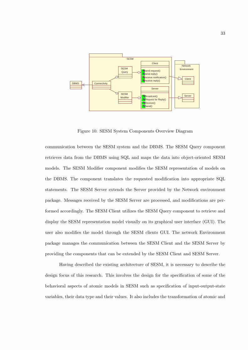
By design, the SESM system includes the SESM package, the Network Environment
package, SESM client, and SESM server as shown in Figure 10. The SESM package should
serve as an API used to access the SESM representation model data stored on the DBMS.
There are three main components in the SESM package; Connectivity, SESM Query, and
SESM Modifier.
The Connectivity component is used to connect to the DBMS. It handles all the
33
SESM
Client
send request() send reply()
receive notification() receive reply()
Server
Broadcast() Request for Reply()
Receive() Send()
SESM
Query
SESM
Modifier
DBMS Connectivity
Network
Environment
Client
Server
Figure 10. SESM System Components Overview Diagram
communication between the SESM system and the DBMS. The SESM Query component
retrieves data from the DBMS using SQL and maps the data into object-oriented SESM
models. The SESM Modifier component modifies the SESM representation of models on
the DBMS. The component translates the requested modification into appropriate SQL
statements. The SESM Server extends the Server provided by the Network environment
package. Messages received by the SESM Server are processed, and modifications are per-
formed accordingly. The SESM Client utilizes the SESM Query component to retrieve and
display the SESM representation model visually on its graphical user interface (GUI). The
user also modifies the model through the SESM clients GUI. The network Environment
package manages the communication between the SESM Client and the SESM Server by
providing the components that can be extended by the SESM Client and SESM Server.
Having described the existing architecture of SESM, it is necessary to describe the
design focus of this research. This involves the design for the specification of some of the
behavioral aspects of atomic models in SESM such as specification of input-output-state
variables, their data type and their values. It also includes the transformation of atomic and
34
coupled models into simulation compatible (DEVSJAVA) format. To achieve this, existing
architecture of SESM is extended. Extensions were made to the client, server and database
designs while keeping the overall architecture of the system same.
2. Database Schema Design for Atomic Model Dynamics
Models developed in SESM are primarily structural. They are described and stored
in a relational database in terms of structural features of the model components such as
identity (i.e., model name), hierarchy (i.e., decomposition), input/output interface (i.e.,
port names) and their creation time. In order to execute (simulate) these models to observe
their behavior in response to input stimulus, they need to be extended in terms of behavioral
aspects of the model. In particular, it is important for an atomic model specification to
support modeling of input and output variables, state variables, and functions. Reusability
of structural and behavioral aspect of these models can be achieved by storing them in a
database. This section presents the SESM behavioral requirements, its relational database
schema and extended Entity-Relationship diagram.
2.1. Requirements. Requirements for the model development based on the three
model categories mentioned in chapter 3 are described in terms of Model, Port and Coupling
[Fu02]. These requirements help in the specification of structure of the models and their
relationship in the relational database. But in addition to the structural requirements, there
are behavioral requirements which are described in terms of port variable, state variable
and NSM variable as follows,
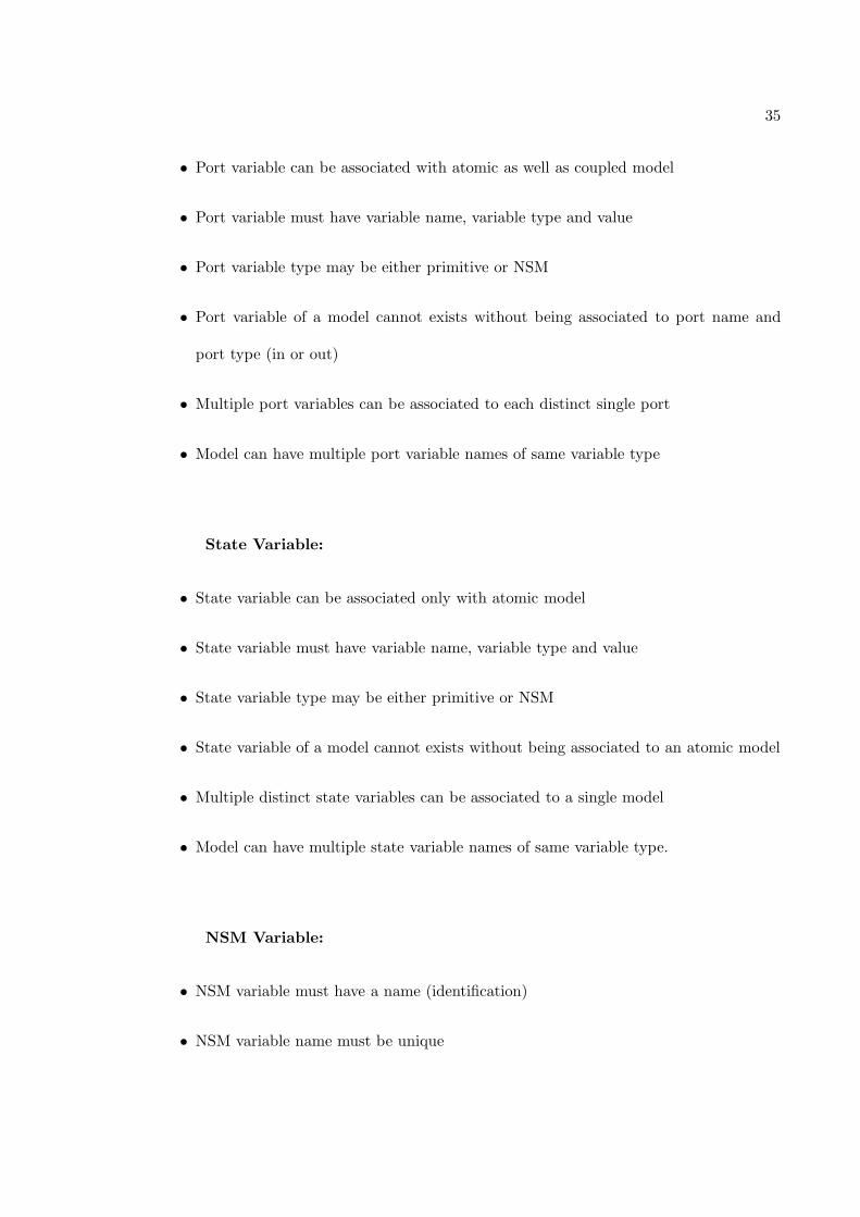
Port Variable:
35
• Port variable can be associated with atomic as well as coupled model
• Port variable must have variable name, variable type and value
• Port variable type may be either primitive or NSM
• Port variable of a model cannot exists without being associated to port name and
port type (in or out)
• Multiple port variables can be associated to each distinct single port
• Model can have multiple port variable names of same variable type
State Variable:
• State variable can be associated only with atomic model
• State variable must have variable name, variable type and value
• State variable type may be either primitive or NSM
• State variable of a model cannot exists without being associated to an atomic model
• Multiple distinct state variables can be associated to a single model
• Model can have multiple state variable names of same variable type.
NSM Variable:
• NSM variable must have a name (identification)
• NSM variable name must be unique
36
• NSM variable can be associated with zero or more models
• NSM variable must be associated with a model as an input, output or state variable
• NSM variable can exists without being associated to a model
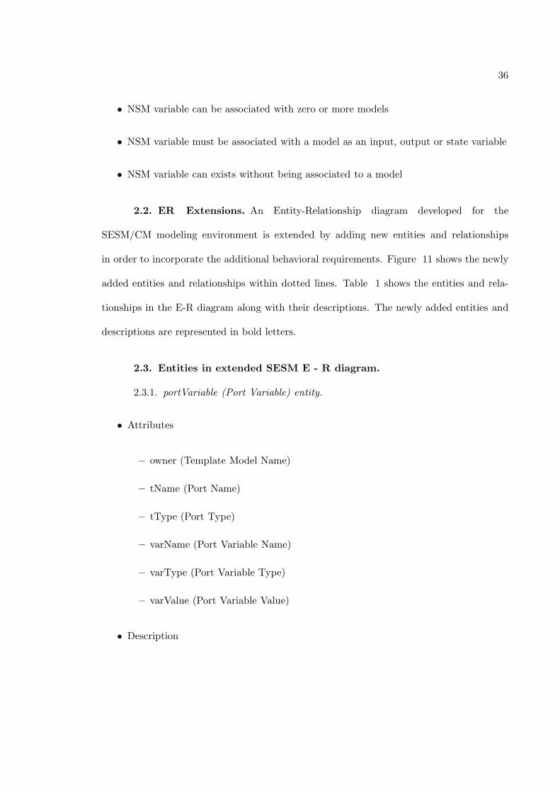
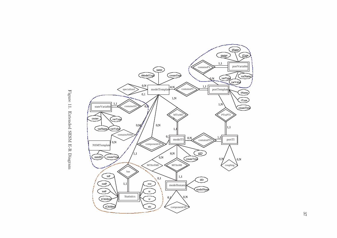
2.2. ER Extensions. An Entity-Relationship diagram developed for the
SESM/CM modeling environment is extended by adding new entities and relationships
in order to incorporate the additional behavioral requirements. Figure 11 shows the newly
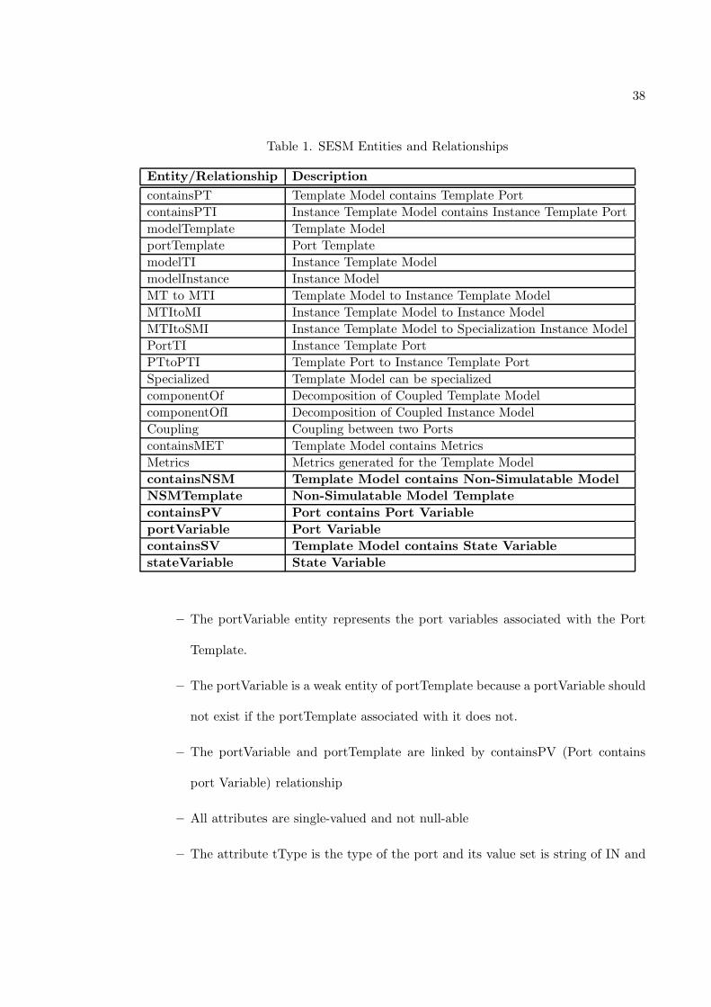
added entities and relationships within dotted lines. Table 1 shows the entities and rela-
tionships in the E-R diagram along with their descriptions. The newly added entities and
descriptions are represented in bold letters.
2.3. Entities in extended SESM E - R diagram.
2.3.1. portVariable (Port Variable) entity.
• Attributes
– owner (Template Model Name)
– tName (Port Name)
– tType (Port Type)
– varName (Port Variable Name)
– varType (Port Variable Type)
– varValue (Port Variable Value)
• Description
37
modelTemplate containsPT portTemplate
componentOf
modelTI
MTtoMT I
containsPTI portTI
MTItoMI MTItoSMI coupling
modelInstance
componentOfI
PTtoPTI
specialized
name
createTime tModelType
tType
createTime
tName
createTime
tiID
iID
modelName
0,N
0,1
0,N 1,1
0,N
1,N
1,N
0,1 0,N
1,1
1,1
1,1
0,N 0,N
0,N 0,N
1,1 0,1
0,1 0,N Statistics
has
1,1
1,1
inP
outP
totP
eic
ic
eoc
tc
iChildren
tChildren
NSMTemplate
containsNSM
stateVariable containsSV
nsmID createTime
varValue
varType
varName
owner
0,N
0,M
1,1 0,N
portVariable containsPV
tType
tName
owner
varValue
varType varName
1,1
0,N
modelTemplate containsPT containsPT portTemplate portTemplate
componentOf componentOf
modelTI modelTI
MTtoMT I MTtoMT I
containsPTI containsPTI portTI portTI
MTItoMI MTItoMI MTItoSMI coupling
modelInstance modelInstance
componentOfI
PTtoPTI PTtoPTI
specialized
name
createTime tModelType
tType
createTime
tName
createTime
tiID
iID
modelName
0,N
0,1
0,N 1,1
0,N
1,N
1,N
0,1 0,N
1,1
1,1
1,1
0,N 0,N
0,N 0,N
1,1 0,1
0,1 0,N Statistics Statistics
has has
1,1
1,1
inP
outP
totP
eic
ic
eoc
tc
iChildren
tChildren
NSMTemplate
containsNSM
stateVariable stateVariable containsSV containsSV
nsmID createTime
varValue
varType
varName
owner
0,N
0,M
1,1 0,N
portVariable portVariable containsPV containsPV
tType
tName
owner
varValue
varType varName
1,1
0,N
Figu
re11.
Exten
ded
SE
SM
E-R
Diagram
38
Table 1. SESM Entities and Relationships
Entity/Relationship Description
containsPT Template Model contains Template Port
containsPTI Instance Template Model contains Instance Template Port
modelTemplate Template Model
portTemplate Port Template
modelTI Instance Template Model
modelInstance Instance Model
MT to MTI Template Model to Instance Template Model
MTItoMI Instance Template Model to Instance Model
MTItoSMI Instance Template Model to Specialization Instance Model
PortTI Instance Template Port
PTtoPTI Template Port to Instance Template Port
Specialized Template Model can be specialized
componentOf Decomposition of Coupled Template Model
componentOfI Decomposition of Coupled Instance Model
Coupling Coupling between two Ports
containsMET Template Model contains Metrics
Metrics Metrics generated for the Template Model
containsNSM Template Model contains Non-Simulatable Model
NSMTemplate Non-Simulatable Model Template
containsPV Port contains Port Variable
portVariable Port Variable
containsSV Template Model contains State Variable
stateVariable State Variable
– The portVariable entity represents the port variables associated with the Port
Template.
– The portVariable is a weak entity of portTemplate because a portVariable should
not exist if the portTemplate associated with it does not.
– The portVariable and portTemplate are linked by containsPV (Port contains
port Variable) relationship
– All attributes are single-valued and not null-able
– The attribute tType is the type of the port and its value set is string of IN and
39
OUT.
2.3.2. stateVariable (State Variable) entity.
• Attributes
– owner (Template Model Name)
– varName (State Variable Name)
– varType (State Variable Type)
– varValue (State Variable Value)
• Description
– The stateVariable entity represents the state variables associated with the mod-
elTemplate
– The stateVariable and modelTemplate are linked by containsSV (Port contains
port Variable) relationship
2.3.3. NSMTemplate (Non-Simulatable Model Template) entity.
• Attributes
– nsmID (Non-Simulatable Model name)
– createTime (Time of Non-Simulatable Model porting)
• Description
– The NSMTemplate entity represents the Non-Simulatable model (i.e., complex
data structures)
40
– All attributes are single-valued and not null-able
– The attribute, nsmID, is the primary key for NSMTemplate since NSM Model is
uniquely identified by its nsmID. The value set of this attribute is alphanumerical
string.
– The attribute createTime records the time when the NSM Model was ported. It
can be used to sort NSM Models
2.4. Relationships in extended SESM E - R diagram.
2.4.1. containsNSM. containsNSM defines the relationship between Template Model
and Non-Simulatable Model. The cardinality of this relationship is M ModelTemplate to N
NSMTemplate as Model Template can have zero or more NSM Templates as their elements
while NSM template also can be a part of zero or more Model Template. In short, NSM
Template can exist without being associated with any Model Template and doesn’t have
dependency relationship with Model Template.
2.4.2. containsPV. containsPV defines the relationship between the Port Template
and Port Variable. It is the identifying relationship of the weak entity, Port Variable. The
cardinality of this relationship is 0, N portVariable to 1 PortTemplate. Since portVariable is
a weak entity, it has total participation in the relationship, while PortTemplate has partial
participation in the relationship since some ports might have zero port variables. In short,
existence of the port variable is dependent on the existence of the port.
2.4.3. containsSV. containsSV defines the relationship between the Model Template
and State Variable. It is the identifying relationship of the weak entity, State Variable. The
cardinality of this relationship is 0, N stateVariable to 1 ModelTemplate. Since stateVariable
is a weak entity, it has total participation in the relationship, while ModelTemplate has
41
partial participation in the relationship since some model templates might have zero state
variables. In short, existence of the state variable is dependent on the existence of the
model.
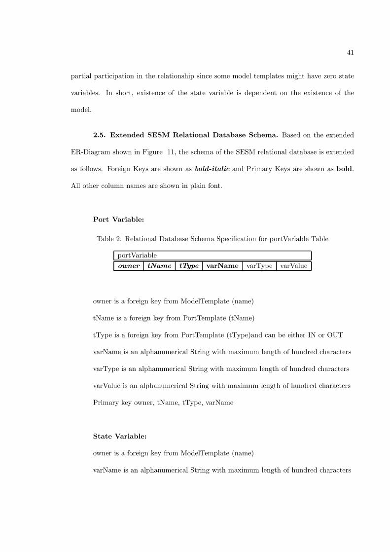
2.5. Extended SESM Relational Database Schema. Based on the extended
ER-Diagram shown in Figure 11, the schema of the SESM relational database is extended
as follows. Foreign Keys are shown as bold-italic and Primary Keys are shown as bold.
All other column names are shown in plain font.
Port Variable:
Table 2. Relational Database Schema Specification for portVariable Table
portVariable
owner tName tType varName varType varValue
owner is a foreign key from ModelTemplate (name)
tName is a foreign key from PortTemplate (tName)
tType is a foreign key from PortTemplate (tType)and can be either IN or OUT
varName is an alphanumerical String with maximum length of hundred characters
varType is an alphanumerical String with maximum length of hundred characters
varValue is an alphanumerical String with maximum length of hundred characters
Primary key owner, tName, tType, varName
State Variable:
owner is a foreign key from ModelTemplate (name)
varName is an alphanumerical String with maximum length of hundred characters
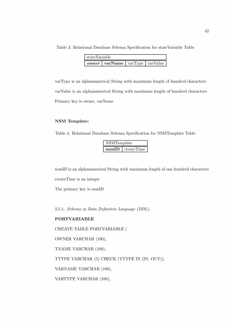
42
Table 3. Relational Database Schema Specification for stateVariable Table
stateVariable
owner varName varType varValue
varType is an alphanumerical String with maximum length of hundred characters
varValue is an alphanumerical String with maximum length of hundred characters
Primary key is owner, varName
NSM Template:
Table 4. Relational Database Schema Specification for NSMTemplate Table
NSMTemplate
nsmID createTime
nsmID is an alphanumerical String with maximum length of one hundred characters
createTime is an integer
The primary key is nsmID
2.5.1. Schema in Data Definition Language (DDL).
PORTVARIABLE
CREATE TABLE PORTVARIABLE (
OWNER VARCHAR (100),
TNAME VARCHAR (100),
TTYPE VARCHAR (5) CHECK (TTYPE IN (IN, OUT)),
VARNAME VARCHAR (100),
VARTYPE VARCHAR (100),
43
VARVALUE VARCHAR (100),
PRIMARY KEY (OWNER, TNAME, TTYPE, VARNAME),
FOREIGN KEY (OWNER) REFERENCES MODELTEMPLATE (TID) ON
DELETE CASCADE,
FOREIGN KEY (TNAME) REFERENCES PORTTEMPLATE (TNAME) ON
DELETE CASCADE,
FOREIGN KEY (TTYPE) REFERENCES PORTTEMPLATE (TTYPE) ON
DELETE CASCADE
)
STATEVARIABLE
CREATE TABLE STATEVARIABLE (
OWNER VARCHAR (100),
VARNAME VARCHAR (100),
VARTYPE VARCHAR (100),
VARVALUE VARCHAR (100),
PRIMARY KEY (OWNER, VARNAME),
FOREIGN KEY (OWNER) REFERENCES MODELTEMPLATE (TID) ON
DELETE CASCADE
)
NSMTEMPLATE
CREATE TABLE NSMTEMPLATE (
NSMID VARCHAR (100),
44
CREATTIME INTEGER,
PRIMARY KEY (NSMID)
)
2.6. Additional constraints. Entity Relationship diagram and data definition
language define different types of constraints like key constraints (primary key, foreign
key), cardinality constraints (one-many or many-many), participation constraints (partial
or total), check constraints, etc. But there are other constraints which cannot be specified
diagrammatically in E-R diagram or syntactically in DDL due to their limitations. These
constraints need to be specified in the underlying programming language (i.e., Java in case
of SESM). Some of these additional constraints are
• The input-output-state variable name and NSM template name must be assigned by
the modeler (user).
• User can add port variables to only ports that already exist in the model.
• Input, output or state variable data type can be either primitive data type (for ex-
ample, integer, float or string in Java language) or of type NSM template.
• When user is choosing NSM template as an input, output or state variable, he should
get a choice of only those NSM templates which are already present in the database.
• User can delete or modify input-output ports or Input-output-state variables which
are associated with the selected model.
2.7. Extended SESM Transactions. SESM environment provides the modeler
the ability to send command and queries. SESM transactions are primarily categorized
45
into three types, Add transactions, Delete Transactions and Modify Transactions which are
further divided into sub-categories such as Add Input port, Add Output port, Delete input
Port, etc. Detailed use case diagrams with additional behavioral requirements for these
transactions are shown in Figure 12, 13 and 14 respectively.
Out of the transactions mentioned in these use cases, current version of SESM/CM
supports following transactions
Add Template Model - add/create a new Template Model
Add Port - add/create an input port or output port to an existing Template Model
Add Component - Add a Template Model as a component to an atomic Template
Model or a coupled Template Model
Add Specialization - add/create a new Template Model as a specialization model
specializes an atomic model or a specialized model
Add Coupling - add/create couplings between two ports
Add Instance Model - add Instance Models from a Template Model
Delete Template Model - Delete an existing Template Model
Delete Port - Delete an existing input port or output port from a Template Model
Delete Component - Delete a component from a coupled model
Delete Coupling - Delete a coupling between two ports
Delete Instance Model - Delete an Instance Model and all its components
Modify Template Model Name - Modify Template Model’s name
Modify Instance Model Name - Modify an Instance Model’s name
Modify Port Name - Modify port’s name
Modify Model Type - Modify Template Model’s type
Show Metrics - Shows structural Metrics of a template Model.
46
But all of these transactions are primarily structural. And as mentioned before, we
need to specify the dynamic characteristics of the model to simulate it and further validate
it. This leads to an additional set of transactions. These transactions are again of type add
(SQL INSERT), delete (SQL DELETE) and modify (SQL MODIFY). Specific examples of
each type of SQL statement with specific key words are shown below for a portVariable
table,
• SQL INSERT: INSERT INTO PORTVARIABLE VALUES (‘PROCESSOR’,
‘ALERTSIGNAL’, ‘IN’, ‘ENT3’, ‘ENTITY’, ‘MAG01’);
• SQL DELETE : DELETE FROM PORTVARIABLE WHERE OWNER = ‘PROCES-
SOR’ AND PORTNAME = ‘ALERTSIGNAL’ AND PORTTYPE = ‘IN’ AND VAR-
NAME = ‘ENT3’ AND VARVALUE = ‘MAG01’;
• SQL UPDATE: UPDATE PORTVARIABLE SET VARTYPE = ‘DOUBLEENT’
AND VARVALUE = ‘MAG02’ WHERE OWNER = ‘PROCESSOR’ AND PORT-
NAME = ‘ALERTSIGNAL’ AND VARVALUE = ‘MAG01’;
The specification of all the extended transactions is as follows,
2.7.1. Add Transactions.
Add Input Port Variable
• Input:
– Port Name
– Variable Name
– Variable Data Type
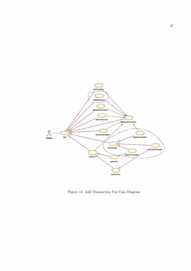
47
addInPort
addOutPort
addInPortVariable
addOutPotVariable
addStateVariable modeler
addModelTemplate
addModelInstance
addSpecialization
addPort
addVariable
addNSMModel
addCoupling
addComponent
add modeler
addInPort
addOutPort
addInPortVariable
addOutPotVariable
addStateVariable modeler
addModelTemplate
addModelInstance
addSpecialization
addPort
addVariable
addNSMModel
addCoupling
addComponent
add modeler
Figure 12. Add Transaction Use Case Diagram
48
– Variable Value
• Restriction:
– Variable must be assigned to port that already exists
– Port type must be by default “IN”.
– Inputted port variable (variable name) doesn’t exist for that input port in the
template model
• Output:
– A new row gets added to portVariable table
• Short Transaction:
– Extract the information regarding the owner model template and port type
– Extract the information regarding port name, variable name, variable data type
and variable value entered by the user
– Create an appropriate event with the input values and send it to server
– Add port variable on a specified port of a selected model (SQL INSERT on
portVariable Table)
Add Output Port Variable
• Input:
– Port Name
49
– Variable Name
– Variable Data Type
– Variable Value
• Restriction:
– Variable must be assigned to port that already exists
– Port type must be by default “OUT”
– Inputted port variable (variable name) doesn’t exist for that output port in the
template model
• Output:
– A new row gets added to portVariable table
• Short Transaction:
– Extract the information regarding the owner model template and port type
– Extract the information regarding port name, variable name, variable data type
and variable value entered by the user
– Create an appropriate event with the input values and send it to server
– Add port variable on a specified port of a selected model (SQL INSERT on
portVariable Table)
Add State Variable
• Input:
50
– Variable Name
– Variable Data Type
– Variable Value
• Restriction:
– Variable must be assigned to model template that already exists
– Variable must be assigned only to atomic model
– Inputted state variable (variable name) doesn’t exist in the template model
• Output:
– new row gets added to stateVariable table
• Short Transaction:
– Extract the information regarding the owner model template
– Extract the information regarding variable name, variable data type and variable
value entered by the user
– Create an appropriate event with the input values and send it to server
– Add state variable to a selected model (SQL INSERT on stateVariable Table)
2.7.2. Delete Transactions.
Delete Input Port Variable
• Input:
– Port Name
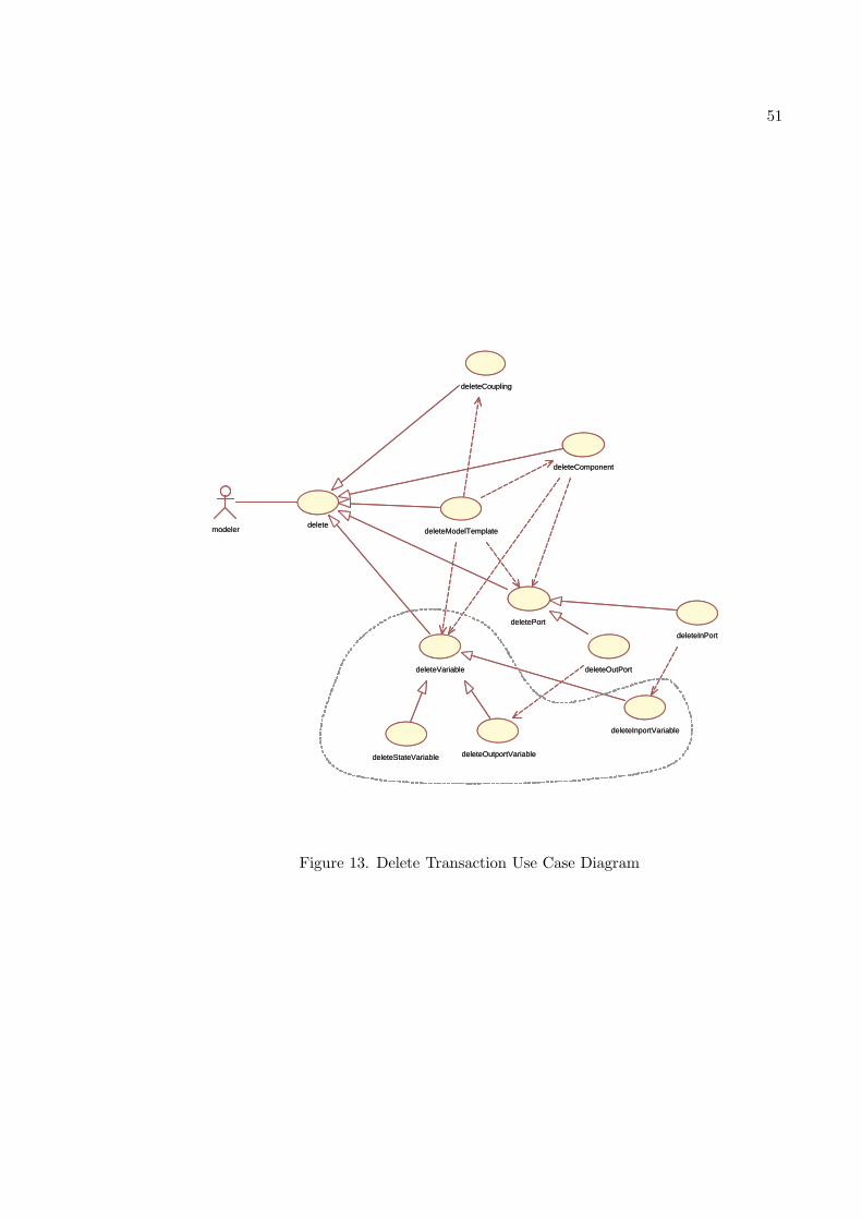
51
deleteInPort
deleteOutPort
deleteInportVariable
deleteOutportVariable
deleteCoupling
deleteComponent
deleteModelTemplate
deletePort
deleteVariable
deleteStateVariable
delete modeler
deleteInPort
deleteOutPort
deleteInportVariable
deleteOutportVariable
deleteCoupling
deleteComponent
deleteModelTemplate
deletePort
deleteVariable
deleteStateVariable
delete modeler
Figure 13. Delete Transaction Use Case Diagram
52
– Variable Name
– Variable Value
– Variable Data Type
• Restriction:
– Port type must be by default “IN”.
– Variable and corresponding port must already exist
• Output:
– An existing row gets deleted from portVariable table
• Short Transaction:
– Extract the information regarding the owner model template and port type
– Extract the information regarding port name, variable name, variable data type
and variable value entered by the user
– Create an appropriate event with the input values and send it to server
– Delete port variable on a specified port of a selected model (SQL DELETE on
portVariable Table)
Delete Output Port Variable
• Input:
– Port Name
53
– Variable Name
– Variable Value
– Variable Data Type
• Restriction:
– Port type must be by default “OUT”
– Variable and corresponding port must already exist
• Output:
– An existing row gets deleted from portVariable table
• Short Transaction:
– Extract the information regarding the owner model template and port type
– Extract the information regarding port name, variable name, variable data type
and variable value entered by the user
– Create an appropriate event with the input values and send it to server
– Delete port variable on a specified port of a selected model (SQL DELETE on
portVariable Table)
Delete State Variable
• Input:
– Variable Name
54
• Restriction:
– Variable must already exists
• Output:
– An existing row gets deleted from stateVariable table
• Short Transaction:
– Extract the information regarding the owner model template
– Extract the information regarding variable name
– Create an appropriate event with the input values and send it to server
– Delete state variable from the selected model (SQL DELETE on stateVariable
Table)
In addition to these direct delete operations, there are other delete operations which
in turn mandate the execution of the above delete operations. They are,
Delete port
• Requirement: When a port of a model is deleted, all the variables associated with the
port must be deleted.
• Design: This is achieved by means of database design by enforcing the referential
integrity constraint between the portTemplate and portVariable table in terms of
columns owner, tName, tType and by cascading the tables upon delete and update
actions.
55
• Execution: Due to the database design, whenever port is deleted from the portTem-
plate table, corresponding rows from the portVariable table having the same values
for owner model, port name and port type is deleted.
Delete Template Model
• Requirement: When an atomic model is deleted, all the state variables associated with
the model as well as all the port variables associated with all the ports of the model
must be deleted. Also, when the coupled models is deleted, all of its port variables
and all the variables associated with its sub-components must be deleted.
• Design: This is again achieved by means of database design by enforcing the referential
integrity constraint between the portTemplate and portVariable table in terms of
columns owner, tName, tType, between ModelTemplate and stateVariable in terms
of column owner and by cascading the tables upon delete and update actions.
• Execution: Due to the database design, whenever the model template is deleted, all
the corresponding ports get deleted which in turn delete all the port variables as
mentioned above. It also deletes corresponding rows in the stateVariable table having
the value for column owner same as that of the model deleted.
2.7.3. Modify Transactions.
Modify Input Port Variable
• Input:
– Port Name
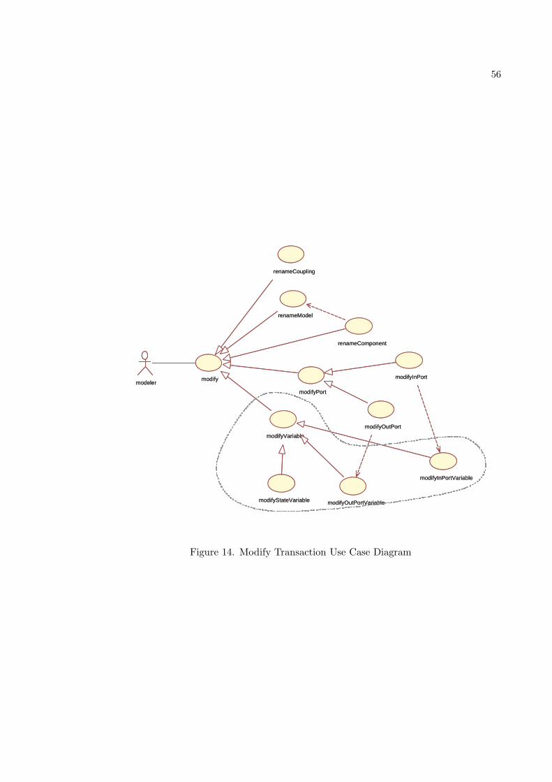
56
renameModel
renameComponent
modifyPort
modifyVariable
modifyInPort
modifyOutPort
modifyInPortVariable
modifyOutPortVariable modifyStateVariable
renameCoupling
modify modeler
renameModel
renameComponent
modifyPort
modifyVariable
modifyInPort
modifyOutPort
modifyInPortVariable
modifyOutPortVariable modifyStateVariable
renameCoupling
modify modeler
Figure 14. Modify Transaction Use Case Diagram
57
– Variable Name
– Variable Value
– Variable Data Type
– New Variable Value
• Restriction:
– Port type must be by default “IN”.
– Variable name, type, value and corresponding port must already exist
• Output:
– An existing row gets modified from portVariable table
• Short Transaction:
– Extract the information regarding the owner model template and port type
– Extract the information regarding port name, variable name, new variable type
and new variable value entered by the user
– Create an appropriate event with the input values and send it to server
– Modify port variable on a specified port of a selected model (SQL MODIFY on
portVariable Table)
Modify Output Port Variable
• Input:
58
– Port Name
– Variable Name
– Variable Value
– Variable Data Type
– New Variable Value
• Restriction:
– Port type must be by default “OUT”
– Variable name, type, value and corresponding port must already exist
• Output:
– An existing row gets modified from portVariable table
• Short Transaction:
– Extract the information regarding the owner model template and port type
– Extract the information regarding port name, variable name, new variable type
and new variable value entered by the user
– Create an appropriate event with the input values and send it to server
– Modify port variable on a specified port of a selected model (SQL MODIFY on
portVariable Table)
Modify State Variable
• Input:
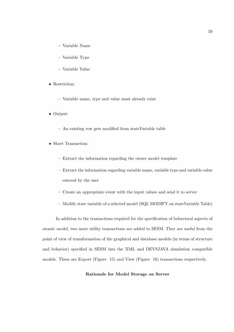
59
– Variable Name
– Variable Type
– Variable Value
• Restriction:
– Variable name, type and value must already exist
• Output:
– An existing row gets modified from stateVariable table
• Short Transaction:
– Extract the information regarding the owner model template
– Extract the information regarding variable name, variable type and variable value
entered by the user
– Create an appropriate event with the input values and send it to server
– Modify state variable of a selected model (SQL MODIFY on stateVariable Table)
In addition to the transactions required for the specification of behavioral aspects of
atomic model, two more utility transactions are added to SESM. They are useful from the
point of view of transformation of the graphical and database models (in terms of structure
and behavior) specified in SESM into the XML and DEVSJAVA simulation compatible
models. These are Export (Figure 15) and View (Figure 16) transactions respectively.
Rationale for Model Storage on Server
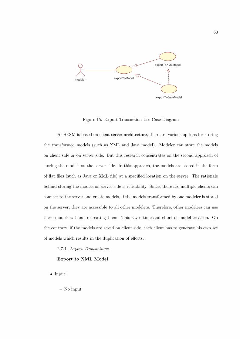
60
exportToJavaModel
exportToXMLModel
exportToModel modeler
Figure 15. Export Transaction Use Case Diagram
As SESM is based on client-server architecture, there are various options for storing
the transformed models (such as XML and Java model). Modeler can store the models
on client side or on server side. But this research concentrates on the second approach of
storing the models on the server side. In this approach, the models are stored in the form
of flat files (such as Java or XML file) at a specified location on the server. The rationale
behind storing the models on server side is reusability. Since, there are multiple clients can
connect to the server and create models, if the models transformed by one modeler is stored
on the server, they are accessible to all other modelers. Therefore, other modelers can use
these models without recreating them. This saves time and effort of model creation. On
the contrary, if the models are saved on client side, each client has to generate his own set
of models which results in the duplication of efforts.
2.7.4. Export Transactions.
Export to XML Model
• Input:
– No input
61
• Restriction:
– Model Template must exists in the database
• Output:
– XML model is created and stored at the particular location on server
• Short Transaction:
– Extract the information regarding model in terms of model name, Model type,
ports, couplings (if coupled), port variables, state variables , variable types and
variable values
– Create an appropriate event with the extracted information and send it to server
– Form a XML document (model) with the received information
– Store the XML model at a particular location on server
Export to DEVSJAVA Model
• Input:
– XML model
• Restriction:
– Model Template and corresponding XML model must already exist in database
and a specified directory respectively on server
• Output:
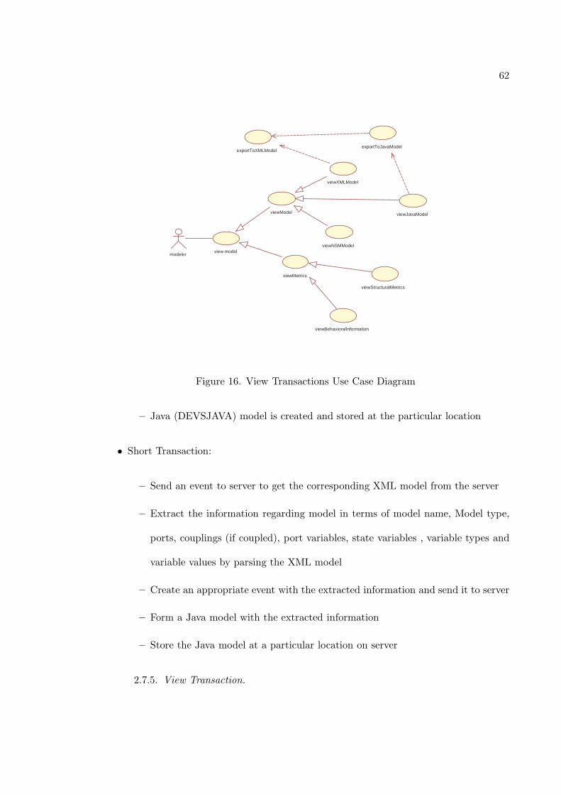
62
exportToXMLModel exportToJavaModel
viewXMLModel
viewJavaModel
viewMetrics
viewStructuralMetrics
viewBehavioralInformation
viewModel
viewNSMModel view model
modeler
Figure 16. View Transactions Use Case Diagram
– Java (DEVSJAVA) model is created and stored at the particular location
• Short Transaction:
– Send an event to server to get the corresponding XML model from the server
– Extract the information regarding model in terms of model name, Model type,
ports, couplings (if coupled), port variables, state variables , variable types and
variable values by parsing the XML model
– Create an appropriate event with the extracted information and send it to server
– Form a Java model with the extracted information
– Store the Java model at a particular location on server
2.7.5. View Transaction.
63
View XML Source Code
• Input:
– XML model
• Restriction:
– XML model must already exists
• Output:
– XML model is viewed in the XML editor
• Short Transaction:
– Send an event to server to get the corresponding XML model from the server
– Read the model and display the model to the user
View Java Source Code
• Input:
– Java model
• Restriction:
– Java model must already exists
• Output:
64
– Java model is viewed in the Java editor
• Short Transaction:
– Send an event to server to get the corresponding Java model from the server
– Read the model and display the model to the user
View Behavioral Information
• Input:
– Template Model
• Restriction:
– Template model must exists in a database
• Output:
– Behavioral information is viewed
• Short Transaction:
– Extract the behavioral information from the model in terms of port and state
variables
– Display this information to the user in to tabular form
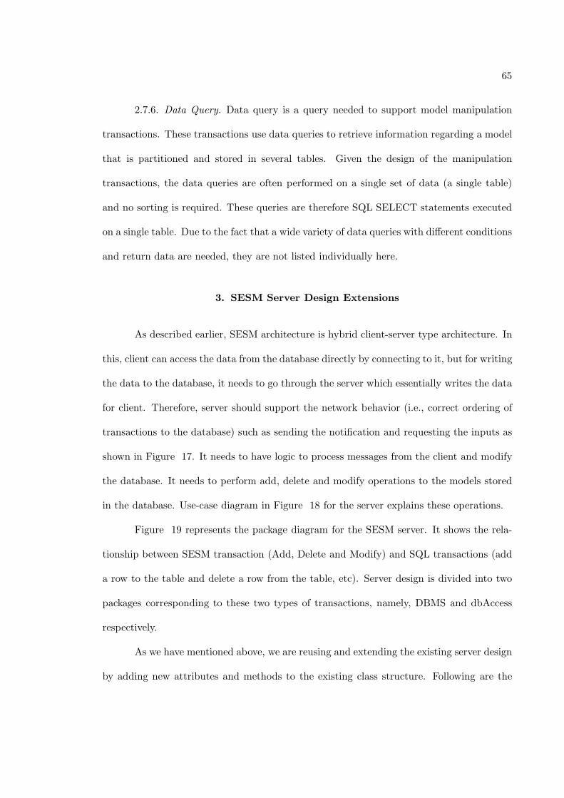
65
2.7.6. Data Query. Data query is a query needed to support model manipulation
transactions. These transactions use data queries to retrieve information regarding a model
that is partitioned and stored in several tables. Given the design of the manipulation
transactions, the data queries are often performed on a single set of data (a single table)
and no sorting is required. These queries are therefore SQL SELECT statements executed
on a single table. Due to the fact that a wide variety of data queries with different conditions
and return data are needed, they are not listed individually here.
3. SESM Server Design Extensions
As described earlier, SESM architecture is hybrid client-server type architecture. In
this, client can access the data from the database directly by connecting to it, but for writing
the data to the database, it needs to go through the server which essentially writes the data
for client. Therefore, server should support the network behavior (i.e., correct ordering of
transactions to the database) such as sending the notification and requesting the inputs as
shown in Figure 17. It needs to have logic to process messages from the client and modify
the database. It needs to perform add, delete and modify operations to the models stored
in the database. Use-case diagram in Figure 18 for the server explains these operations.
Figure 19 represents the package diagram for the SESM server. It shows the rela-
tionship between SESM transaction (Add, Delete and Modify) and SQL transactions (add
a row to the table and delete a row from the table, etc). Server design is divided into two
packages corresponding to these two types of transactions, namely, DBMS and dbAccess
respectively.
As we have mentioned above, we are reusing and extending the existing server design
by adding new attributes and methods to the existing class structure. Following are the
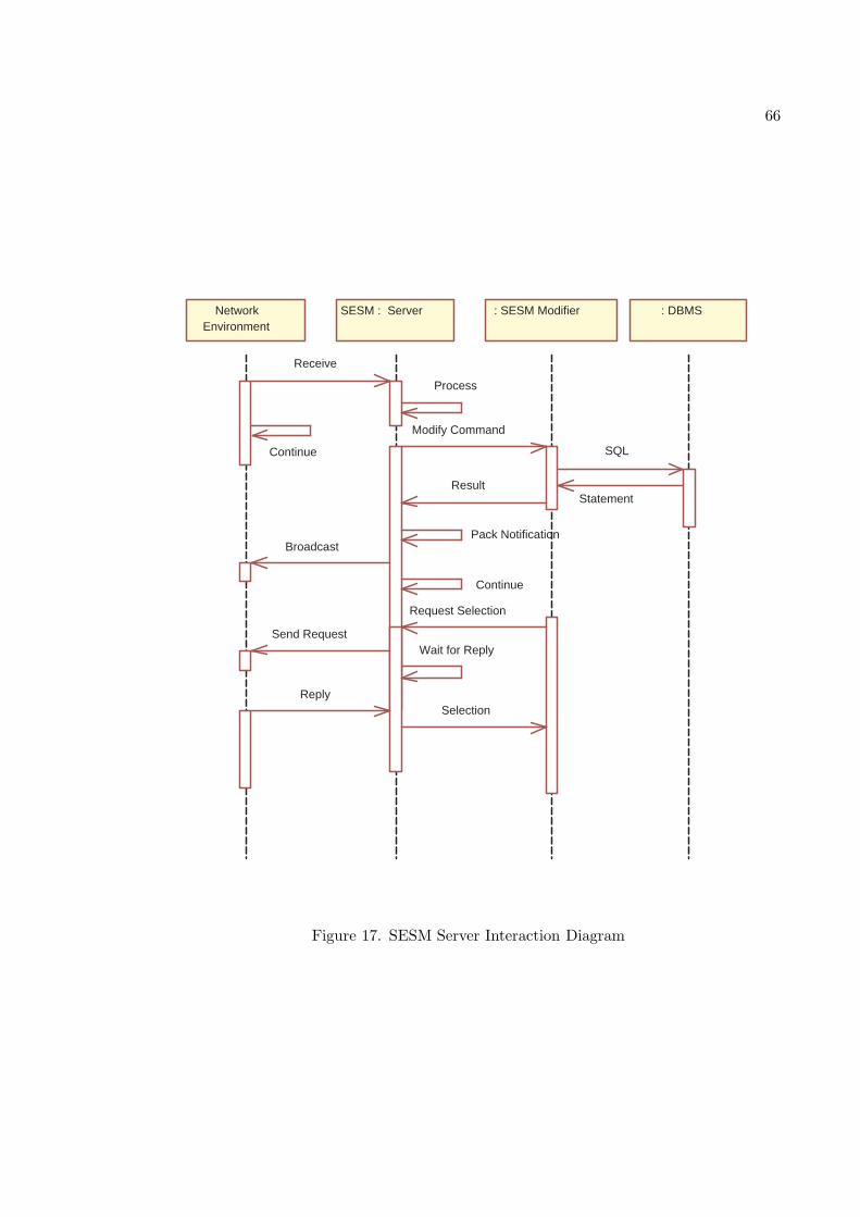
66
Network Environment
SESM : Server : DBMS
Continue
Receive
Process
Broadcast
Continue
Pack Notification
: SESM Modifier
Modify Command
SQL
Statement Result
Request Selection
Send Request Wait for Reply
Reply Selection
Figure 17. SESM Server Interaction Diagram
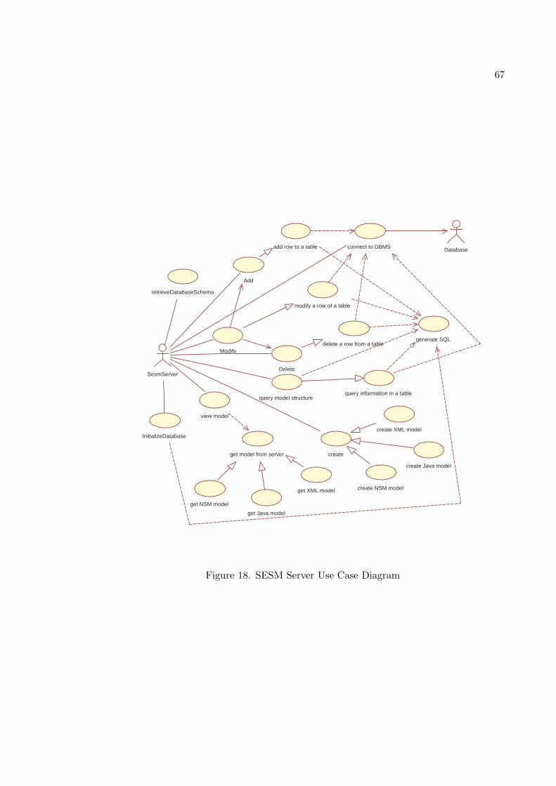
67
add row to a table
modify a row of a table
delete a row from a table
query information in a table
generate SQL
create XML model
create Java model
create NSM model
Database
retrieveDatabaseSchema
Add
Modify
Delete
InitializeDatabase
query model structure
connect to DBMS
create
view model
SesmServer
get model from server
get XML model
get Java model
get NSM model
Figure 18. SESM Server Use Case Diagram
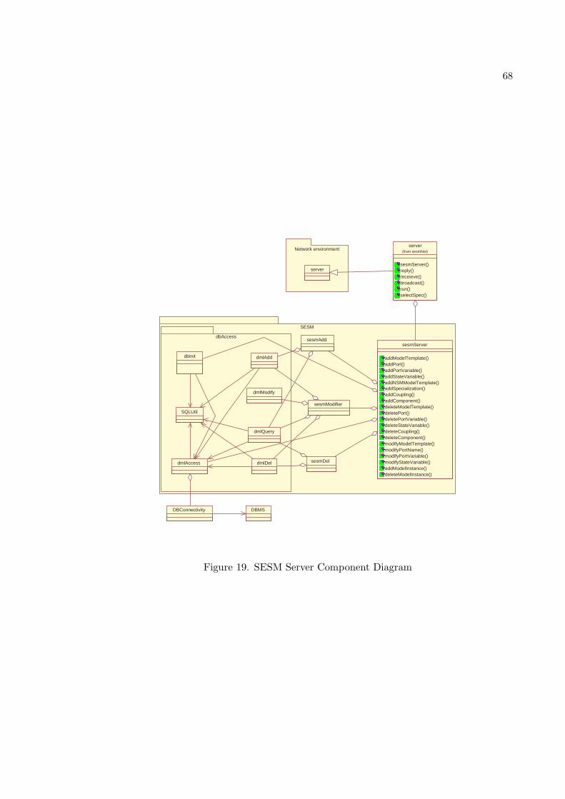
68
SESM
dbAccess
Network environment
server
SQLUtil
dmlAdd
dmlModify
dmlQuery
dmlDel
sesmAdd
sesmModifier
sesmDel
dbInit
dmlAccess
DBConnectivity DBMS
server
sesmServer() reply() receieve() broadcast() run() selectSpec()
(from sesmNet)
sesmServer
addModelTemplate() addPort() addPortVariable() addStateVariable() addNSMModelTemplate() addSpecialization() addCoupling() addComponent() deleteModelTemplate() deletePort() deletePortVariable() deleteStateVariable() deleteCoupling() deleteComponent() modifyModelTemplate() modifyPortName() modifyPortVariable() modifyStateVariable() addModelInstance() deleteModelInstance()
Figure 19. SESM Server Component Diagram
69
extension to the existing classes in the server design.
3.1. dbms package. This package provides classes (sesmDb, sesmAdd, sesmDel,
sesmModify and sesmQuery), with the methods that are directly mapped to the transac-
tions. Classes in this package cannot directly access the database. For that, they have to go
through the short transactions defined later in the dbAccess package. This package focuses
on defining the transactions of SESM.
sesmDB Class
The sesmDB object provides all the operations required to manipulate the database
according to the SESM. The primary functions of this object are checking correctness of
the input and interface with users.
• Existing Attributes
– theQuery: SESM.sesmQuery object used to perform queries retrieving SESM
model information
– add: SESM.sesmAdd object used to perform add operations in SESM models
– delete: SESM.sesmDel object used to perform delete operations on SESM models
– modify: SESM.sesmModify object used to perform modify operations in SESM
models
• New Methods
– addNsmModelTemplate: add a new NSM model template to the relational data-
base
70
– delNsmModelTemplate: delete existing NSM model template from the relational
database
– addPortVariable: add a port variable to an specific existing port of a model
– addStateVariable: add a state variable to a model
– delPortVariable: delete a port variable of specific existing port of a model
– delStateVariable: delete a state variable of a model
– modifyPortVariable: modify a port variable of specific existing port of a model
– modifyStateVariable: modify a state variable of a model
• Existing Methods:
– addModelTemplate: add a new model template to the relational database
– addPort: add a port to an existing model
– addComponent: add a component to an existing model
– addSpecialization: create a specializing model from an existing model
– addCoupling: couple two existing ports
– addModelInstance: create a new model instance from a model template
– delModelTemplate: delete an existing model template
– delPort: delete a port from a model template
– delComponent: delete a component from a model template
– delCoupling: delete an existing coupling
– delModelInstance: delete an existing model instance at the root level
– modifyModelTemplate: modify the name of an existing model template
71
– modifyPortName: modify the name of a port
– modifyModelName: modify the name of an existing model instance
– requestUserInput: request the user to select a specializing model for a specialized
model. Abstract method should be implemented by the collaborative environ-
ment
sesmAdd Class
The sesmAdd class extends the SESM.dbAccess.dmlAdd class to perform add trans-
actions of SESM.
• Existing Attributes
– theQuery: SESM.access.dmlQuery object used to query for model information
• New Methods
– modelNsmT: add a new NSM model template to the relational database
– portVariable: add a new port variable to an existing port of a model
– stateVariable: add a new state variable to a model
• Existing Methods:
– modelT: add a new model template to the relational database
– port: add a port to an existing model
– compomentOf: add a component to an existing model
– specialization: create a specializing model from an existing model
72
– coupling: couple two existing ports
– instance: create a new model instance from a model template
sesmDel Class
The sesmDel class extends the SESM.dbAccess.dmlDel class to perform delete trans-
actions of SESM.
• Existing Attributes
– theQuery: SESM.access.dmlQuery object used to query for model information
• New Methods
– modelNsmT: delete an existing NSM model from relational database
– portVariable: delete an existing port variable of an existing port of a model
– stateVariable: delete an existing state variable to a model
• Existing Methods:
– delModelTemplate: delete an existing model template
– delPort: delete a port from a model template
– delComponent: delete a component from a model template
– delCoupling: delete an existing coupling
– delModelInstance: delete an existing model instance at the root level
sesmModify Class
73
The sesmModify class extends the SESM.dbAccess.dmlModify class to perform mod-
ify transactions of SESM.
• Existing Attributes
– theQuery: SESM.access.dmlQuery object used to query for model information
– add: SESM.access.dmlAdd object used to restore the modified values
– delete: SESM.access.dmlDel object used to delete the old values
• New Methods
– portVariableName: modify an existing port variable of an existing port of a
model
– stateVariableName: modify an existing state variable to a model
• Existing Methods:
– modifyModelTemplate: modify the name of an existing model template
– modifyPortName: modify the name of a port
– modifyModelName: modify the name of an existing model instance
3.2. dbAccess package. This package provides classes (dbInit, dmlAccess, dm-
lAdd, dmlDel, dmlModify, and dmlQuery, query, and SQLUtil), which can manipulate and
query the relational database. The schemas defined here are for the relational database.
Therefore, all transactions included in the SESM.access package are short transactions ex-
pressed in SQL.
74
SQLUtil Class
The SQLUtil class provides static methods to generate SQL statements from generic
variables.
• Existing Methods:
– dropTable: generate SQL DROP TABLE (DML) statement to drop a table
– createTable: generate SQL CREATE TABLE (DDL) statement to create a table
– insert: generate SQL INSERT (DML) statement to insert a new row into a table
– delete: generate SQL DELETE (DML) statement to delete a row from a table
– update: generate SQL UPDATE (DML) statement to update rows in a table
– query: generate SQL SELECT (DML) statement to query the database
dmlAccess Class
The dmlAccess class provides connectivity between the application and the RDBMS.
Other than controlling a connection between the application and the relational database,
this class also manages all transactions to enforce atomicity.
• Existing Attributes
– userID: the user name for the relational database
– password: the password for the relational database
– ip: the ip address of the relational database system
– dbID: the identification of the relational database management system
75
– dbConnect: the JDBC connection provided by the relational database manage-
ment system vendor.
• Existing Methods:
– open: open a connection to the relational database
– close: close the current opened connection
– exeSQL: execute a SQL statement (perform an atomic transaction) without re-
turn values
– connectionInfo: get the current connection information
– checkConnection: check to see if a connection is opened
– startTransaction: start a long transaction
– endTransaction: end a long transaction
dbInit Class
The dbInit class contains static variables mapped from the SESM database schema
and it provides the method to initialize the relational database
• New Attributes
– NSMTEMPLATE, NSM ID, PORTVARIABLE, PT VARNAME,
PT VARTYPE, PT VARVALUE, STATEVARIABLE, ST OWNER,
ST VARNAME, ST VARTYPE, ST VARVALUE
• Existing Attributes
76
– SESM Database Schema: static variables
– dbConnect: connectivity to the relational database.
• Existing Methods:
– initDB: initialize the relational database currently connecting to. All the previous
data in the database is erased. The schema is then defined in the relational
database.
– createAllTables: defines all the table schema
– dropAllTables: drops all the table schema
dmlAdd Class
The dmlAdd class performs add operations (SQL INSERT) on database.
• Existing Attributes
– dbConnect: connectivity to the relational database
– theQuery: to query the data from the database.
• New Methods
– modelNSMT: insert a new row into the NSMTemplate table
– portVariableT: insert a new row into the portVariable table
– stateVariableT: insert a new row into the stateVariable table
• Existing Methods:
– modelT: insert a new row into the modelTemplate table
77
– modelTI: insert a new row into the modelTI table
– port: insert a new row into the portTemplate table
– portTI: insert a new row into the portTI table
– compomentOf: insert a new row into the componentOf table
– coupling: insert a new row into the coupling table
– modelI: insert a new row into the modelInstance table
– MTItoSMI: insert a new row into the MTItoSMI table
– componentOfI: insert a new row into the componentOfI table
– addRow: insert a new row to a particular table
dmlDel Class
The dmlDel class performs delete operations (SQL DELETE) on the database
• Existing Attributes
– dbConnect: connectivity to the relational database.
• New Methods
– portVariableT: delete a row in the portVariable table
– stateVariableT: delete a row in the stateVariable table
• Existing Methods:
– modelT: delete a row in the modelTemplate table
– modelTI: delete a row in the modelTI table
78
– port: delete a row in the portTemplate table
– portTI: delete a row in the portTI table
– compomentOf: delete a row in the componentOf table
– coupling: delete a row in the coupling table
– modelI: delete a row in the modelInstance table
– MTItoSMI: delete a row in the MTItoSMI table
– componentOfI: delete a row in the componentOfI table
– deleteRow: delete a row in a particular table
dmlModify Class
The dmlModify class performs modify operations (SQL UPDATE) on database
• Existing Attributes
– dbConnect: connectivity to the relational database.
• New Methods
– portVariable: modify a row in the portVariable table
– stateVariable: modify a row in the stateVariable table
• Existing Methods:
– modelName: modify the model template name (Name) in the modelTemplate
table
79
– modelType: modify the model template type (modelType) in the modelTemplate
table
– instanceName: modify the model instance name (modelName) in the modelIn-
stance table
– modifyRow: modify a row in a particular table
dmlQuery Class
The dmlQuery class performs query operations (SQL SELECT) on database
• Existing Attributes
– dbConnect: connectivity to the relational database.
• New Methods
– modelNSMT: query the NSM template(s) from NSMTemplate table
– portVariableT: query port variable name from portVariable table
– portVariableTypeT: query port variable data type from portVariable table
– portVariableValueT: query port variable value from portVariable table
– stateVariableT: query state variable name from stateVariable table
– stateVariableTypeT: query state variable data type from stateVariable table
– stateVariableValueT: query state variable value from stateVariable table
– getNsmModels: query the names of all the existing NSM models
• Existing Methods:
80
– modelT: query the modelTemplate table
– modelTI: query the modelTI table
– port: query the portTemplate table
– portTI: query the portTI table
– componentOf: query the componentOf table
– coupling: query the coupling table
– modelI: query the modelInstance table
– MTItoSMI: query the MTItoSMI table
– componentOfI: query the componentOfI table
– getData: query a particular table
3.3. sesmNet package.
ServerUtility Class
This new class is added to provide the utilities to the server to deal with the events
sent by the user to create, view, modify three different types of the models namely, XML,
Java or NSM models.
• Methods
– createFile: generic method which creates different types of files for models (XML,
Java, NSM) in appropriate folders on the server.
– isFilePresent: generic method to check whether a particular type of method is
present in a particular folder on server.
– getOverWritePermission: generic method to get the permission for overwriting
the file in a particular folder on server
81
– writeToFile: generic method to write the contents of the file and send return
event to client upon completion
– getFile: method to get XML file on the server to create corresponding Java model
– viewFile: generic method to process view event of the client and send him a
correct file from the server to view it on client
– addNsmToDB: method to add NSM model to database.
In addition to this, the existing code of the sesmNet.sesmServer, sesmNet.sesmClient
and sesmEvent.sesmEvent classes is extended to incorporate the functionalities related to
the creation, deletion and modification of port variables, state variables and creation, mod-
ification and viewing of NSM models, XML models and Java Models.
The sequence diagram details sequence of server operations for adding a state vari-
able to an atomic model depicting the relationship between different SESM transactions
and SQL transactions is shown in Figure 20.
4. SESM Client Design Extensions
In SESM architecture, client is one of the four major components. The client can
create, delete or modify the model data by sending a request with required parameters to
the server as shown in Figure 21. The clients requests are serialized if they are intended to
modify the model. The serialization ensures that the server receives only a single request
at a time. When the server receives the modification request, it broadcasts the notification
to all the clients associated with it. When the client receives the notification from the
server, it reads the model data directly from the database, refreshes the GUI accordingly
and notifies the user about the modifications made. If a request for reply from the Server
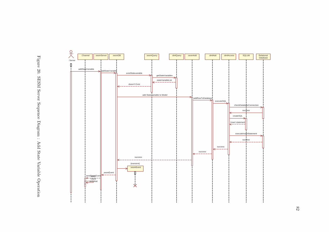
82
:dmlQuery
: Server
:sesmServer :sesmDB
:sesmEvent
:sesmQuery :sesmAdd :dmlAdd :dmlAccess SQLUtil Relational Database
:Channel
addStateVariable addStateVariable
existStatevariable getStateVariables
stateVariableList
doesn't Exist
add State variable to Model
addRowToDatabase executeSQL
checkDatabaseConnection
success
createSQL
Insert statement
success
success
success
{transient}
sesmEvent
sendSesmEvent notify Client
and Wait
executeInsertStatement
success
Figu
re20.
SE
SM
Server
Seq
uen
ceD
iagram:
Add
State
Variab
leO
peration
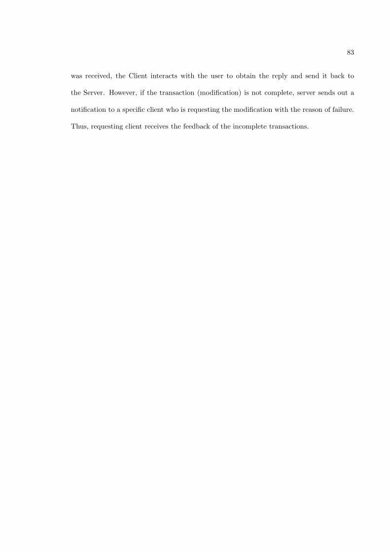
83
was received, the Client interacts with the user to obtain the reply and send it back to
the Server. However, if the transaction (modification) is not complete, server sends out a
notification to a specific client who is requesting the modification with the reason of failure.
Thus, requesting client receives the feedback of the incomplete transactions.
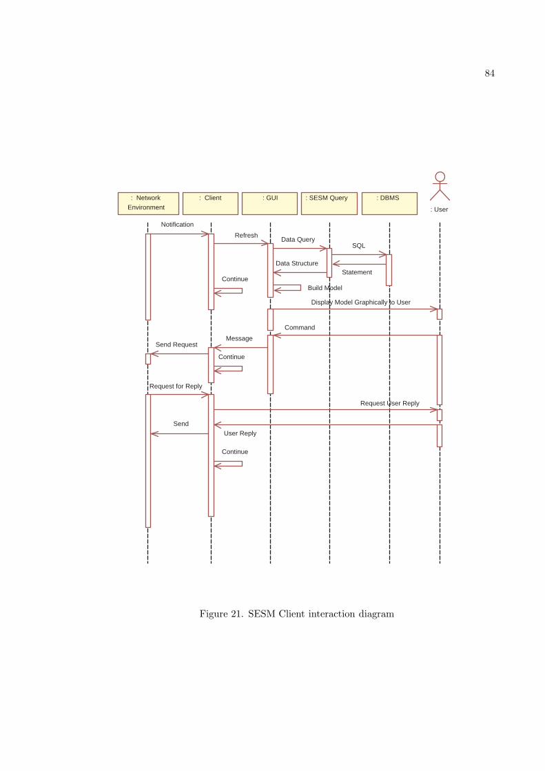
84
: GUI : SESM Query : DBMS
: User
: Network
Environment
: Client
Notification
Refresh Data Query
SQL
Statement Data Structure
Build Model
Display Model Graphically to User
Command
Message Send Request
Continue
Request for Reply
Request User Reply
User Reply
Send
Continue
Continue
Figure 21. SESM Client interaction diagram
CHAPTER 5
USER INTERFACE DESIGN
1. Client GUI Analysis
The graphical user interface (GUI) of the SESM modeling environment (as shown
in Figure 2) is divided in to three main divisions, namely
• Model Tree Structure: This view represents the model data, stored in the database, in
a hierarchical tree like structure. It maintains three types of trees - Template Model
tree (TM), Instance Template tree (ITM) and Instance Model Tree (IM).
• Model Components: This view creates graphical representation of model structure,
ports, couplings and components to make them easy to read and manipulate.
• Command Menu: This is a pop-up menu provided to the user to interact easily with
the visual models and to manipulate them.
All these three areas of the client GUI are extended in order to support the objectives
of this research as well as to provide better interaction and better view for the user.
1.1. Model Tree Structure Extension. This view is extended to support Non-
Simulatable Model Tree (NSM) as shown on the left-hand side in Figure 22. Also, simulat-
able model trees and non-simulatable model tree are separated from each other by putting
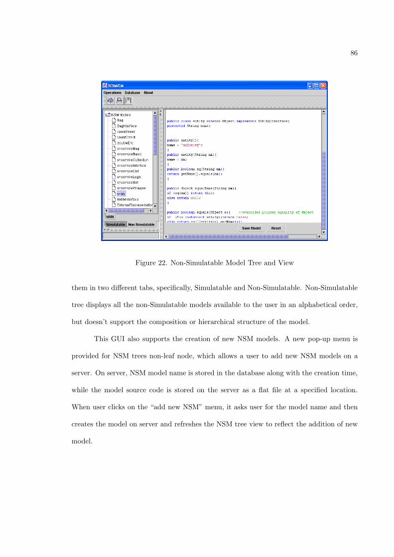
86
Figure 22. Non-Simulatable Model Tree and View
them in two different tabs, specifically, Simulatable and Non-Simulatable. Non-Simulatable
tree displays all the non-Simulatable models available to the user in an alphabetical order,
but doesn’t support the composition or hierarchical structure of the model.
This GUI also supports the creation of new NSM models. A new pop-up menu is
provided for NSM trees non-leaf node, which allows a user to add new NSM models on a
server. On server, NSM model name is stored in the database along with the creation time,
while the model source code is stored on the server as a flat file at a specified location.
When user clicks on the “add new NSM” menu, it asks user for the model name and then
creates the model on server and refreshes the NSM tree view to reflect the addition of new
model.
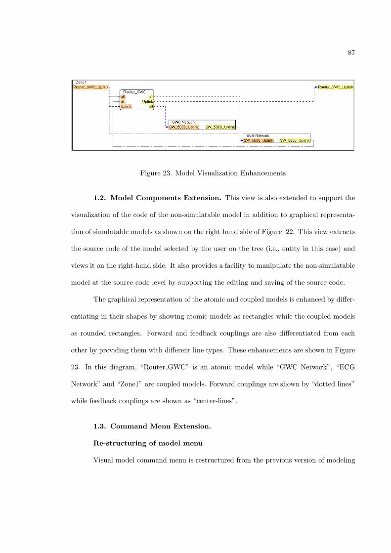
87
Figure 23. Model Visualization Enhancements
1.2. Model Components Extension. This view is also extended to support the
visualization of the code of the non-simulatable model in addition to graphical representa-
tion of simulatable models as shown on the right hand side of Figure 22. This view extracts
the source code of the model selected by the user on the tree (i.e., entity in this case) and
views it on the right-hand side. It also provides a facility to manipulate the non-simulatable
model at the source code level by supporting the editing and saving of the source code.
The graphical representation of the atomic and coupled models is enhanced by differ-
entiating in their shapes by showing atomic models as rectangles while the coupled models
as rounded rectangles. Forward and feedback couplings are also differentiated from each
other by providing them with different line types. These enhancements are shown in Figure
23. In this diagram, “Router GWC” is an atomic model while “GWC Network”, “ECG
Network” and “Zone1” are coupled models. Forward couplings are shown by “dotted lines”
while feedback couplings are shown as “center-lines”.
1.3. Command Menu Extension.
Re-structuring of model menu
Visual model command menu is restructured from the previous version of modeling
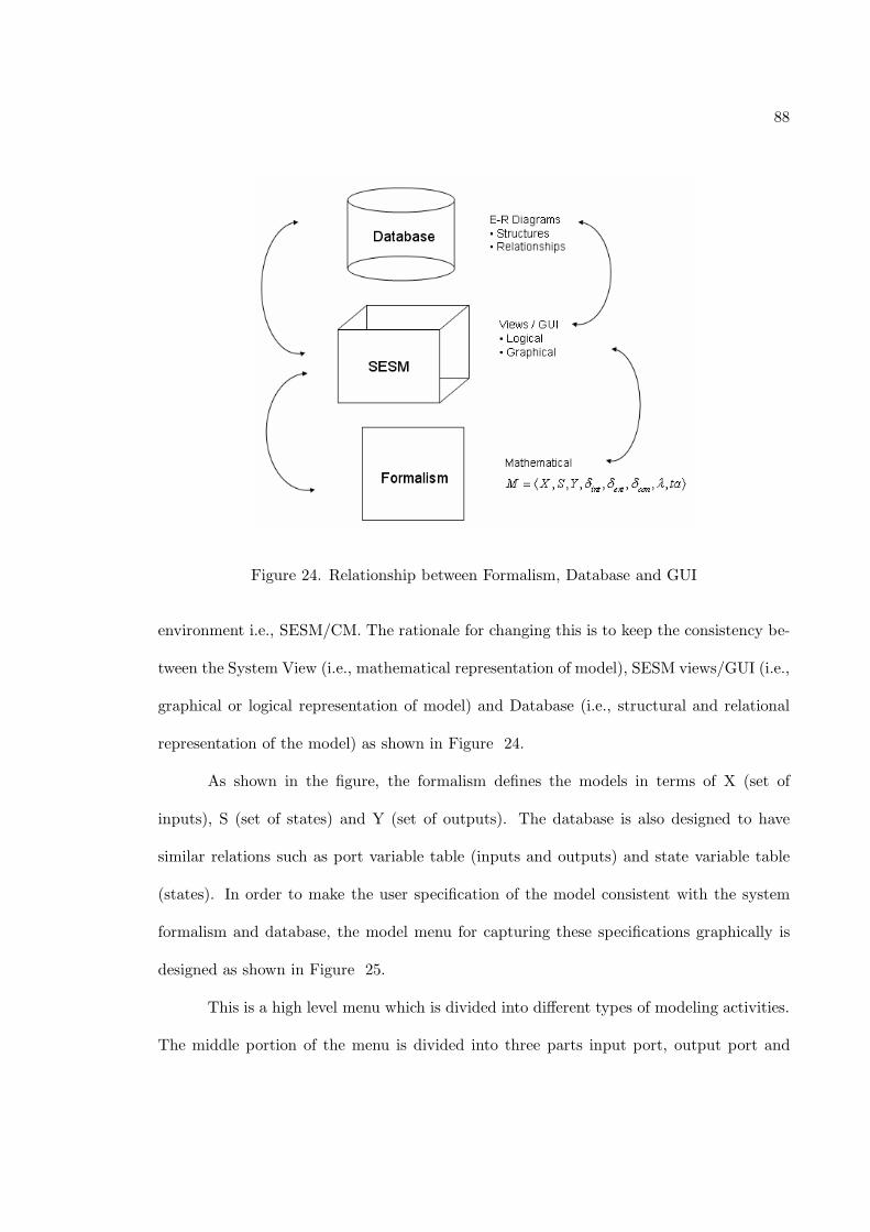
88
Figure 24. Relationship between Formalism, Database and GUI
environment i.e., SESM/CM. The rationale for changing this is to keep the consistency be-
tween the System View (i.e., mathematical representation of model), SESM views/GUI (i.e.,
graphical or logical representation of model) and Database (i.e., structural and relational
representation of the model) as shown in Figure 24.
As shown in the figure, the formalism defines the models in terms of X (set of
inputs), S (set of states) and Y (set of outputs). The database is also designed to have
similar relations such as port variable table (inputs and outputs) and state variable table
(states). In order to make the user specification of the model consistent with the system
formalism and database, the model menu for capturing these specifications graphically is
designed as shown in Figure 25.
This is a high level menu which is divided into different types of modeling activities.
The middle portion of the menu is divided into three parts input port, output port and
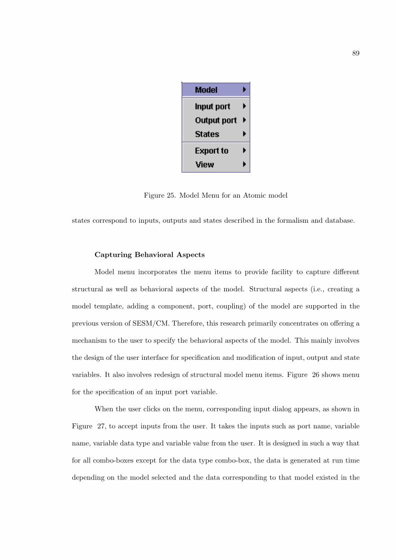
89
Figure 25. Model Menu for an Atomic model
states correspond to inputs, outputs and states described in the formalism and database.
Capturing Behavioral Aspects
Model menu incorporates the menu items to provide facility to capture different
structural as well as behavioral aspects of the model. Structural aspects (i.e., creating a
model template, adding a component, port, coupling) of the model are supported in the
previous version of SESM/CM. Therefore, this research primarily concentrates on offering a
mechanism to the user to specify the behavioral aspects of the model. This mainly involves
the design of the user interface for specification and modification of input, output and state
variables. It also involves redesign of structural model menu items. Figure 26 shows menu
for the specification of an input port variable.
When the user clicks on the menu, corresponding input dialog appears, as shown in
Figure 27, to accept inputs from the user. It takes the inputs such as port name, variable
name, variable data type and variable value from the user. It is designed in such a way that
for all combo-boxes except for the data type combo-box, the data is generated at run time
depending on the model selected and the data corresponding to that model existed in the
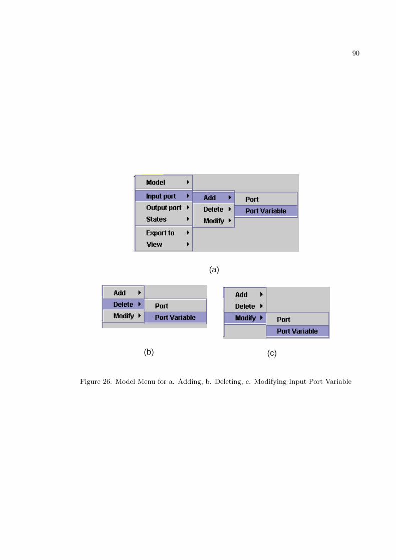
90
(a)
(b) (c)
Figure 26. Model Menu for a. Adding, b. Deleting, c. Modifying Input Port Variable
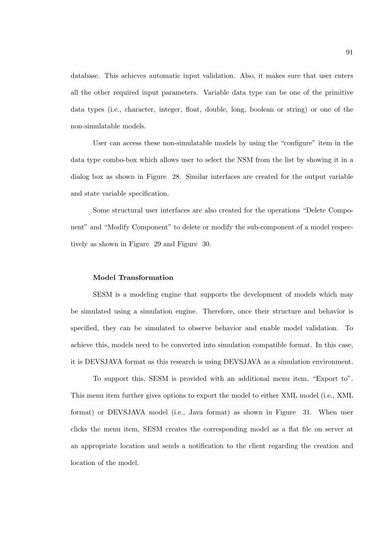
91
database. This achieves automatic input validation. Also, it makes sure that user enters
all the other required input parameters. Variable data type can be one of the primitive
data types (i.e., character, integer, float, double, long, boolean or string) or one of the
non-simulatable models.
User can access these non-simulatable models by using the “configure” item in the
data type combo-box which allows user to select the NSM from the list by showing it in a
dialog box as shown in Figure 28. Similar interfaces are created for the output variable
and state variable specification.
Some structural user interfaces are also created for the operations “Delete Compo-
nent” and “Modify Component” to delete or modify the sub-component of a model respec-
tively as shown in Figure 29 and Figure 30.
Model Transformation
SESM is a modeling engine that supports the development of models which may
be simulated using a simulation engine. Therefore, once their structure and behavior is
specified, they can be simulated to observe behavior and enable model validation. To
achieve this, models need to be converted into simulation compatible format. In this case,
it is DEVSJAVA format as this research is using DEVSJAVA as a simulation environment.
To support this, SESM is provided with an additional menu item, “Export to”.
This menu item further gives options to export the model to either XML model (i.e., XML
format) or DEVSJAVA model (i.e., Java format) as shown in Figure 31. When user
clicks the menu item, SESM creates the corresponding model as a flat file on server at
an appropriate location and sends a notification to the client regarding the creation and
location of the model.
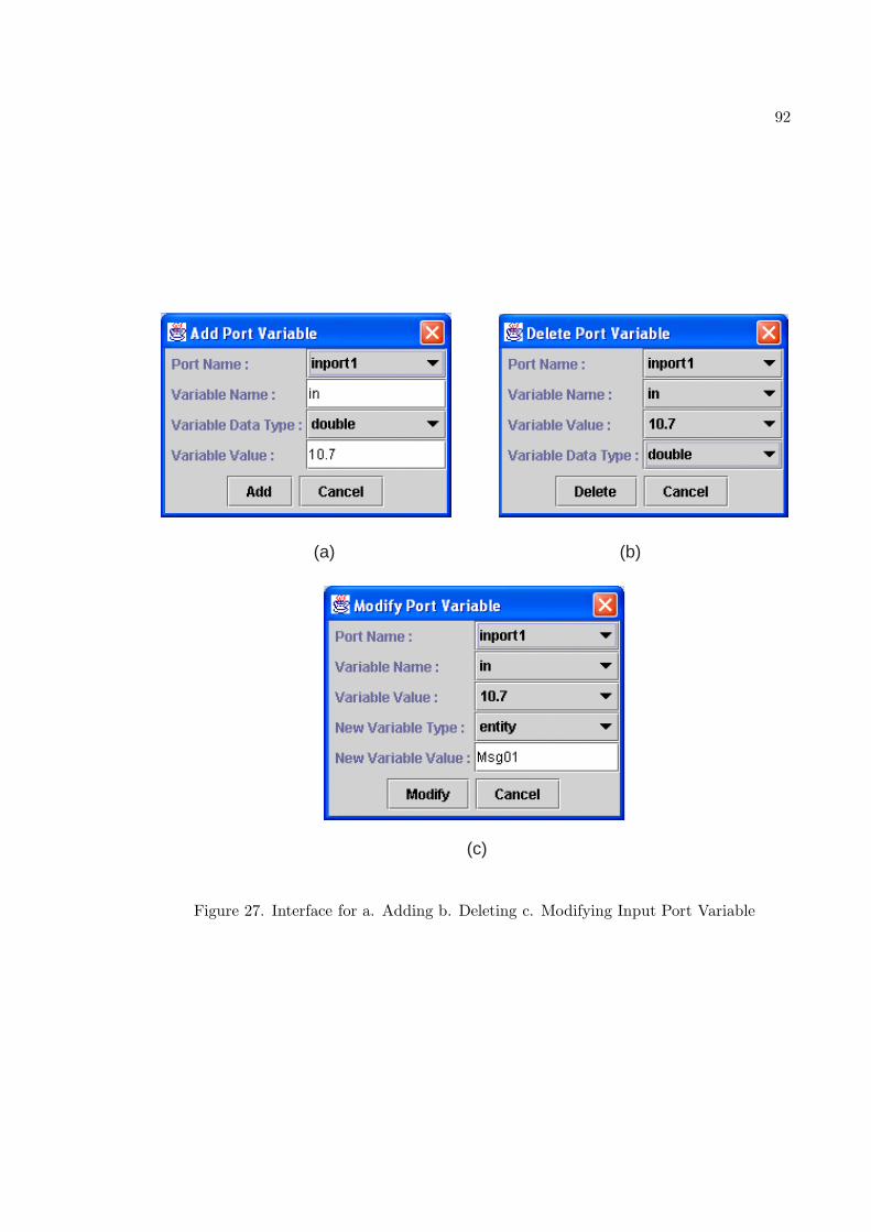
92
(a) (b)
(c)
Figure 27. Interface for a. Adding b. Deleting c. Modifying Input Port Variable
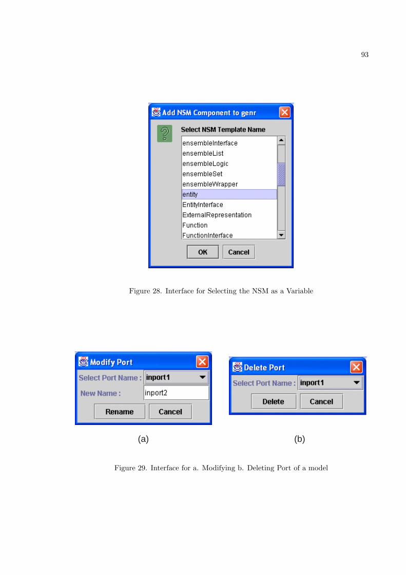
93
Figure 28. Interface for Selecting the NSM as a Variable
(a) (b)
Figure 29. Interface for a. Modifying b. Deleting Port of a model
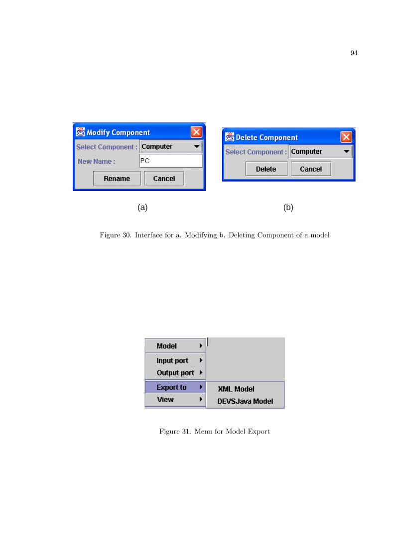
94
(a) (b)
Figure 30. Interface for a. Modifying b. Deleting Component of a model
Figure 31. Menu for Model Export
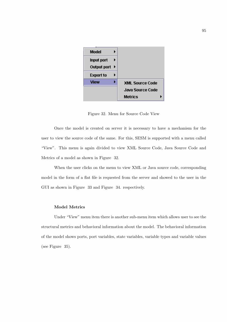
95
Figure 32. Menu for Source Code View
Once the model is created on server it is necessary to have a mechanism for the
user to view the source code of the same. For this, SESM is supported with a menu called
“View”. This menu is again divided to view XML Source Code, Java Source Code and
Metrics of a model as shown in Figure 32.
When the user clicks on the menu to view XML or Java source code, corresponding
model in the form of a flat file is requested from the server and showed to the user in the
GUI as shown in Figure 33 and Figure 34. respectively.
Model Metrics
Under “View” menu item there is another sub-menu item which allows user to see the
structural metrics and behavioral information about the model. The behavioral information
of the model shows ports, port variables, state variables, variable types and variable values
(see Figure 35).
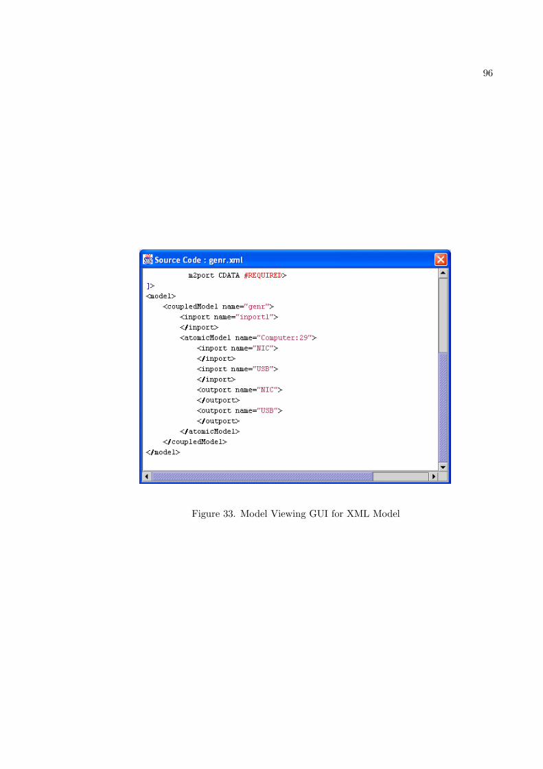
96
Figure 33. Model Viewing GUI for XML Model
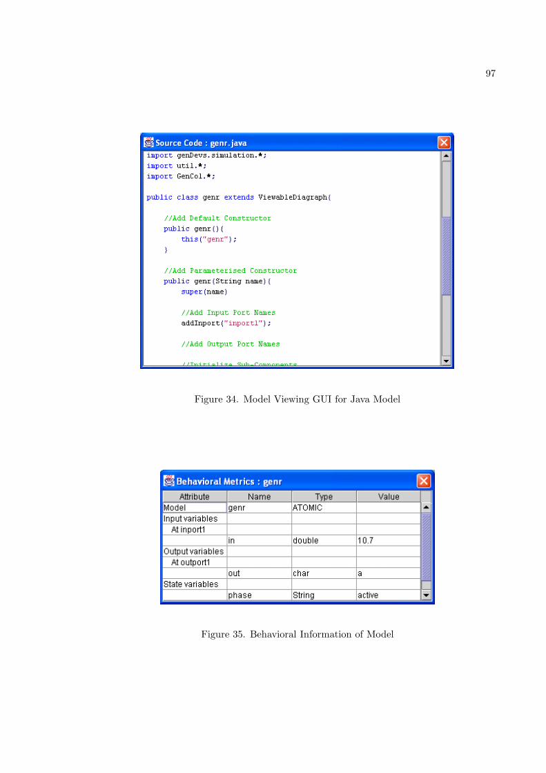
97
Figure 34. Model Viewing GUI for Java Model
Figure 35. Behavioral Information of Model
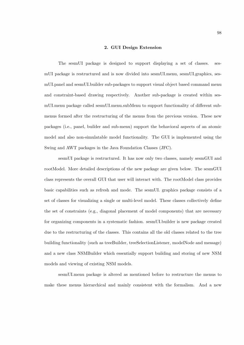
98
2. GUI Design Extension
The sesmUI package is designed to support displaying a set of classes. ses-
mUI package is restructured and is now divided into sesmUI.menu, sesmUI.graphics, ses-
mUI.panel and sesmUI.builder sub-packages to support visual object based command menu
and constraint-based drawing respectively. Another sub-package is created within ses-
mUI.menu package called sesmUI.menu.subMenu to support functionality of different sub-
menus formed after the restructuring of the menus from the previous version. These new
packages (i.e., panel, builder and sub-menu) support the behavioral aspects of an atomic
model and also non-simulatable model functionality. The GUI is implemented using the
Swing and AWT packages in the Java Foundation Classes (JFC).
sesmUI package is restructured. It has now only two classes, namely sesmGUI and
rootModel. More detailed descriptions of the new package are given below. The sesmGUI
class represents the overall GUI that user will interact with. The rootModel class provides
basic capabilities such as refresh and mode. The sesmUI. graphics package consists of a
set of classes for visualizing a single or multi-level model. These classes collectively define
the set of constraints (e.g., diagonal placement of model components) that are necessary
for organizing components in a systematic fashion. sesmUI.builder is new package created
due to the restructuring of the classes. This contains all the old classes related to the tree
building functionality (such as treeBuilder, treeSelectionListener, modelNode and message)
and a new class NSMBuilder which essentially support building and storing of new NSM
models and viewing of existing NSM models.
sesmUI.menu package is altered as mentioned before to restructure the menus to
make these menus hierarchical and mainly consistent with the formalism. And a new
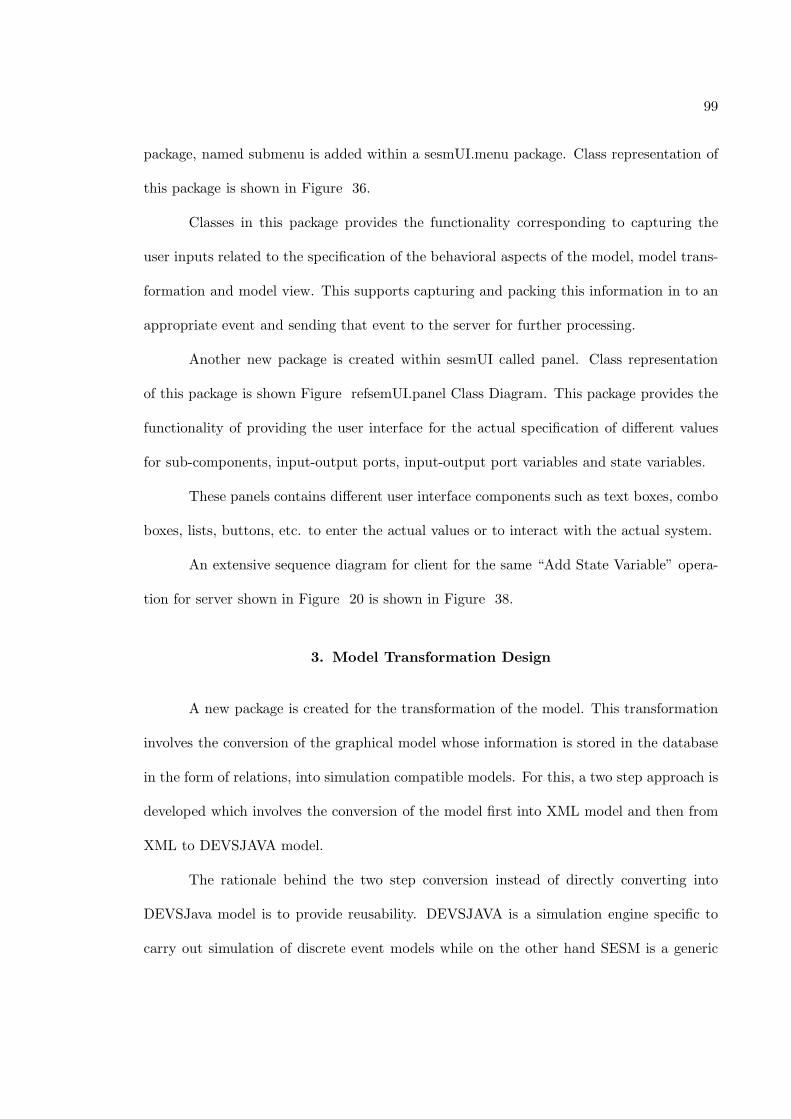
99
package, named submenu is added within a sesmUI.menu package. Class representation of
this package is shown in Figure 36.
Classes in this package provides the functionality corresponding to capturing the
user inputs related to the specification of the behavioral aspects of the model, model trans-
formation and model view. This supports capturing and packing this information in to an
appropriate event and sending that event to the server for further processing.
Another new package is created within sesmUI called panel. Class representation
of this package is shown Figure refsemUI.panel Class Diagram. This package provides the
functionality of providing the user interface for the actual specification of different values
for sub-components, input-output ports, input-output port variables and state variables.
These panels contains different user interface components such as text boxes, combo
boxes, lists, buttons, etc. to enter the actual values or to interact with the actual system.
An extensive sequence diagram for client for the same “Add State Variable” opera-
tion for server shown in Figure 20 is shown in Figure 38.
3. Model Transformation Design
A new package is created for the transformation of the model. This transformation
involves the conversion of the graphical model whose information is stored in the database
in the form of relations, into simulation compatible models. For this, a two step approach is
developed which involves the conversion of the model first into XML model and then from
XML to DEVSJAVA model.
The rationale behind the two step conversion instead of directly converting into
DEVSJava model is to provide reusability. DEVSJAVA is a simulation engine specific to
carry out simulation of discrete event models while on the other hand SESM is a generic
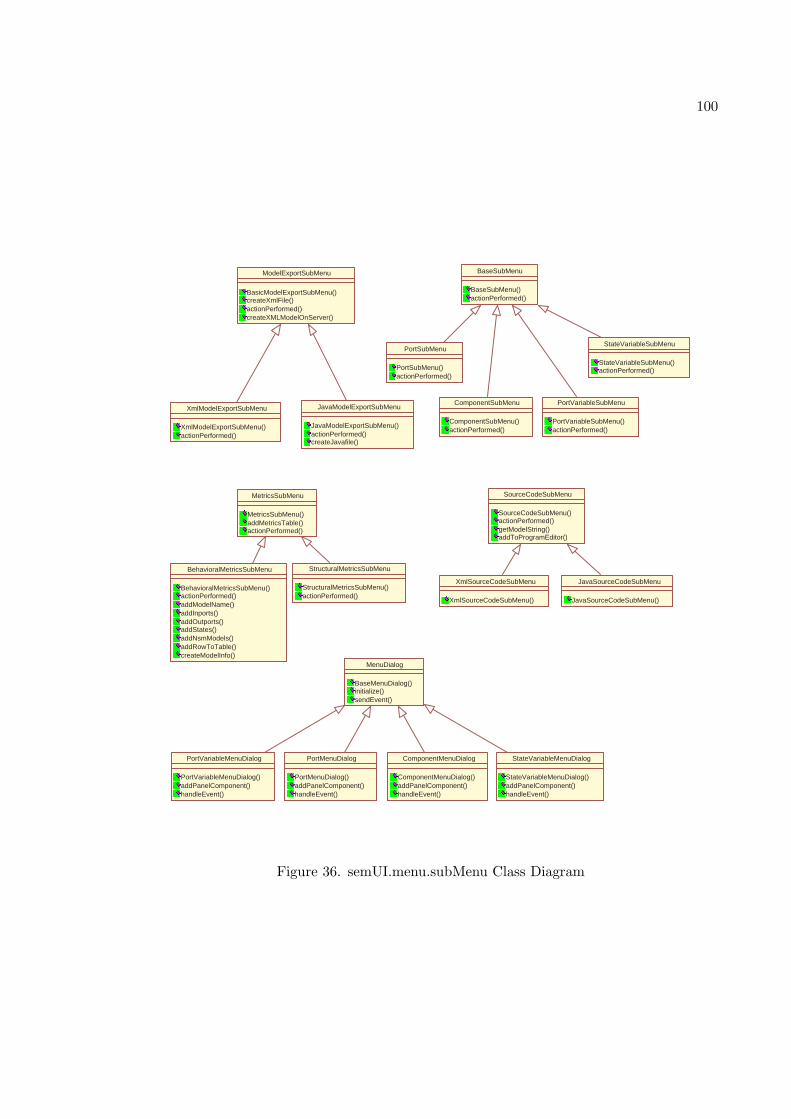
100
MenuDialog
BaseMenuDialog() initialize() sendEvent()
BaseSubMenu
BaseSubMenu() actionPerformed()
ModelExportSubMenu
BasicModelExportSubMenu() createXmlFile() actionPerformed() createXMLModelOnServer()
BehavioralMetricsSubMenu
BehavioralMetricsSubMenu() actionPerformed() addModelName() addInports() addOutports() addStates() addNsmModels() addRowToTable() createModelInfo()
ComponentMenuDialog
ComponentMenuDialog() addPanelComponent() handleEvent()
ComponentSubMenu
ComponentSubMenu() actionPerformed()
JavaModelExportSubMenu
JavaModelExportSubMenu() actionPerformed() createJavafile()
MetricsSubMenu
MetricsSubMenu() addMetricsTable() actionPerformed()
PortMenuDialog
PortMenuDialog() addPanelComponent() handleEvent()
PortSubMenu
PortSubMenu() actionPerformed()
PortVariableMenuDialog
PortVariableMenuDialog() addPanelComponent() handleEvent()
PortVariableSubMenu
PortVariableSubMenu() actionPerformed()
StateVariableMenuDialog
StateVariableMenuDialog() addPanelComponent() handleEvent()
StateVariableSubMenu
StateVariableSubMenu() actionPerformed()
StructuralMetricsSubMenu
StructuralMetricsSubMenu() actionPerformed()
XmlModelExportSubMenu
XmlModelExportSubMenu() actionPerformed()
JavaSourceCodeSubMenu
JavaSourceCodeSubMenu()
SourceCodeSubMenu
SourceCodeSubMenu() actionPerformed() getModelString() addToProgramEditor()
XmlSourceCodeSubMenu
XmlSourceCodeSubMenu()
Figure 36. semUI.menu.subMenu Class Diagram
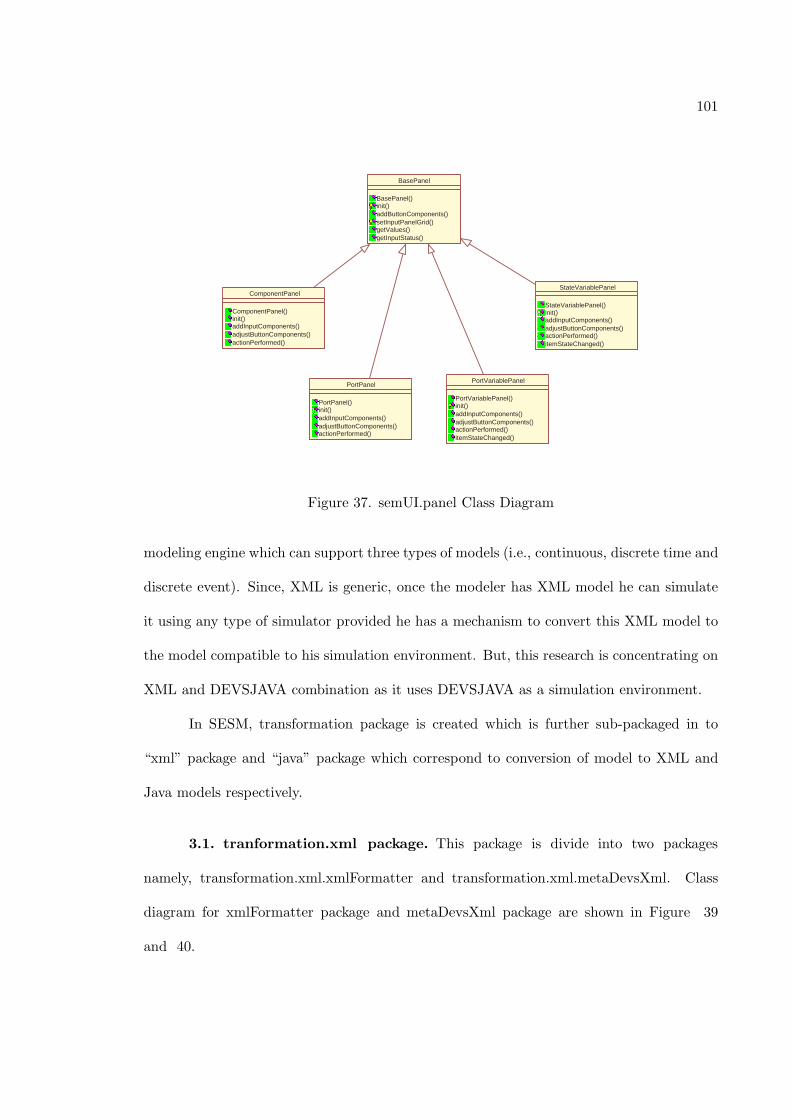
101
BasePanel
BasePanel() init() addButtonComponents() setInputPanelGrid() getValues() getInputStatus()
ComponentPanel
ComponentPanel() init() addInputComponents() adjustButtonComponents() actionPerformed()
PortPanel
PortPanel() init() addInputComponents() adjustButtonComponents() actionPerformed()
PortVariablePanel
PortVariablePanel() init() addInputComponents() adjustButtonComponents() actionPerformed() itemStateChanged()
StateVariablePanel
StateVariablePanel() init() addInputComponents() adjustButtonComponents() actionPerformed() itemStateChanged()
Figure 37. semUI.panel Class Diagram
modeling engine which can support three types of models (i.e., continuous, discrete time and
discrete event). Since, XML is generic, once the modeler has XML model he can simulate
it using any type of simulator provided he has a mechanism to convert this XML model to
the model compatible to his simulation environment. But, this research is concentrating on
XML and DEVSJAVA combination as it uses DEVSJAVA as a simulation environment.
In SESM, transformation package is created which is further sub-packaged in to
“xml” package and “java” package which correspond to conversion of model to XML and
Java models respectively.
3.1. tranformation.xml package. This package is divide into two packages
namely, transformation.xml.xmlFormatter and transformation.xml.metaDevsXml. Class
diagram for xmlFormatter package and metaDevsXml package are shown in Figure 39
and 40.

102
: modeler :ModelITMenu :AddMenu :StateVariableS ubMenu
:StateVariable MenuDialog
:StateVariableP anel
:sesmEvent :sesmClient :channel :InportMenu
{transient} {transient} {transient}
Open Model Menu
Continue
Click "States"
Click "Add"
Click "State Variable"
<<Created>>
<<Created>>
Add Panel To Dialog
pack
get Input Status
check User Inputs
Input Status
get Input Values
Input Values
<<Created>>
set Input Values
Send Sesm Event
Send Sesm Event
Notify Server and Wait
Figu
re38.
Clien
tSeq
uen
ceD
iagram:
Add
State
Variab
leO
peration
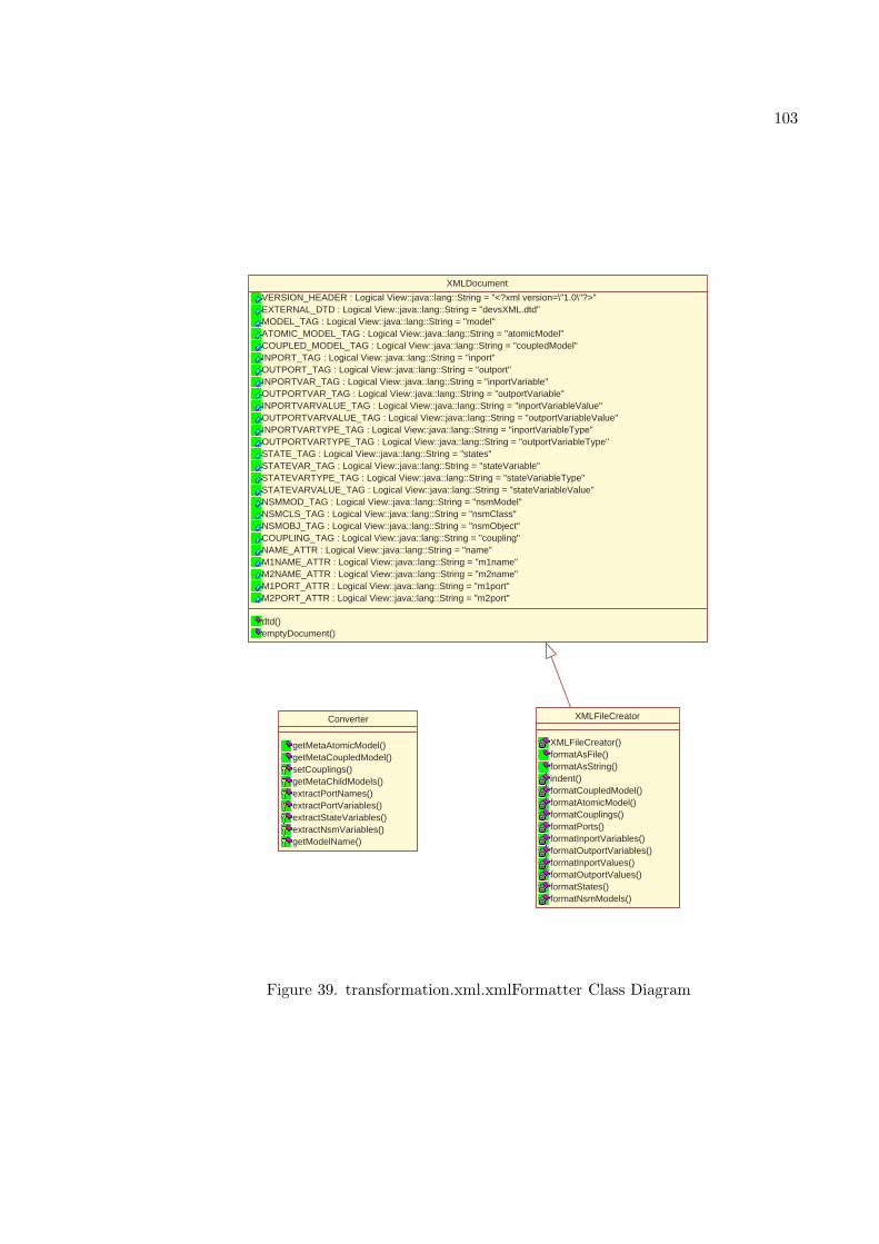
103
Converter
getMetaAtomicModel() getMetaCoupledModel() setCouplings() getMetaChildModels() extractPortNames() extractPortVariables() extractStateVariables() extractNsmVariables() getModelName()
XMLDocument
VERSION_HEADER : Logical View::java::lang::String = "<?xml version=\"1.0\"?>" EXTERNAL_DTD : Logical View::java::lang::String = "devsXML.dtd" MODEL_TAG : Logical View::java::lang::String = "model" ATOMIC_MODEL_TAG : Logical View::java::lang::String = "atomicModel" COUPLED_MODEL_TAG : Logical View::java::lang::String = "coupledModel" INPORT_TAG : Logical View::java::lang::String = "inport" OUTPORT_TAG : Logical View::java::lang::String = "outport" INPORTVAR_TAG : Logical View::java::lang::String = "inportVariable" OUTPORTVAR_TAG : Logical View::java::lang::String = "outportVariable" INPORTVARVALUE_TAG : Logical View::java::lang::String = "inportVariableValue" OUTPORTVARVALUE_TAG : Logical View::java::lang::String = "outportVariableValue" INPORTVARTYPE_TAG : Logical View::java::lang::String = "inportVariableType" OUTPORTVARTYPE_TAG : Logical View::java::lang::String = "outportVariableType" STATE_TAG : Logical View::java::lang::String = "states" STATEVAR_TAG : Logical View::java::lang::String = "stateVariable" STATEVARTYPE_TAG : Logical View::java::lang::String = "stateVariableType" STATEVARVALUE_TAG : Logical View::java::lang::String = "stateVariableValue" NSMMOD_TAG : Logical View::java::lang::String = "nsmModel" NSMCLS_TAG : Logical View::java::lang::String = "nsmClass" NSMOBJ_TAG : Logical View::java::lang::String = "nsmObject" COUPLING_TAG : Logical View::java::lang::String = "coupling" NAME_ATTR : Logical View::java::lang::String = "name" M1NAME_ATTR : Logical View::java::lang::String = "m1name" M2NAME_ATTR : Logical View::java::lang::String = "m2name" M1PORT_ATTR : Logical View::java::lang::String = "m1port" M2PORT_ATTR : Logical View::java::lang::String = "m2port"
dtd() emptyDocument()
XMLFileCreator
XMLFileCreator() formatAsFile() formatAsString() indent() formatCoupledModel() formatAtomicModel() formatCouplings() formatPorts() formatInportVariables() formatOutportVariables() formatInportValues() formatOutportValues() formatStates() formatNsmModels()
Figure 39. transformation.xml.xmlFormatter Class Diagram
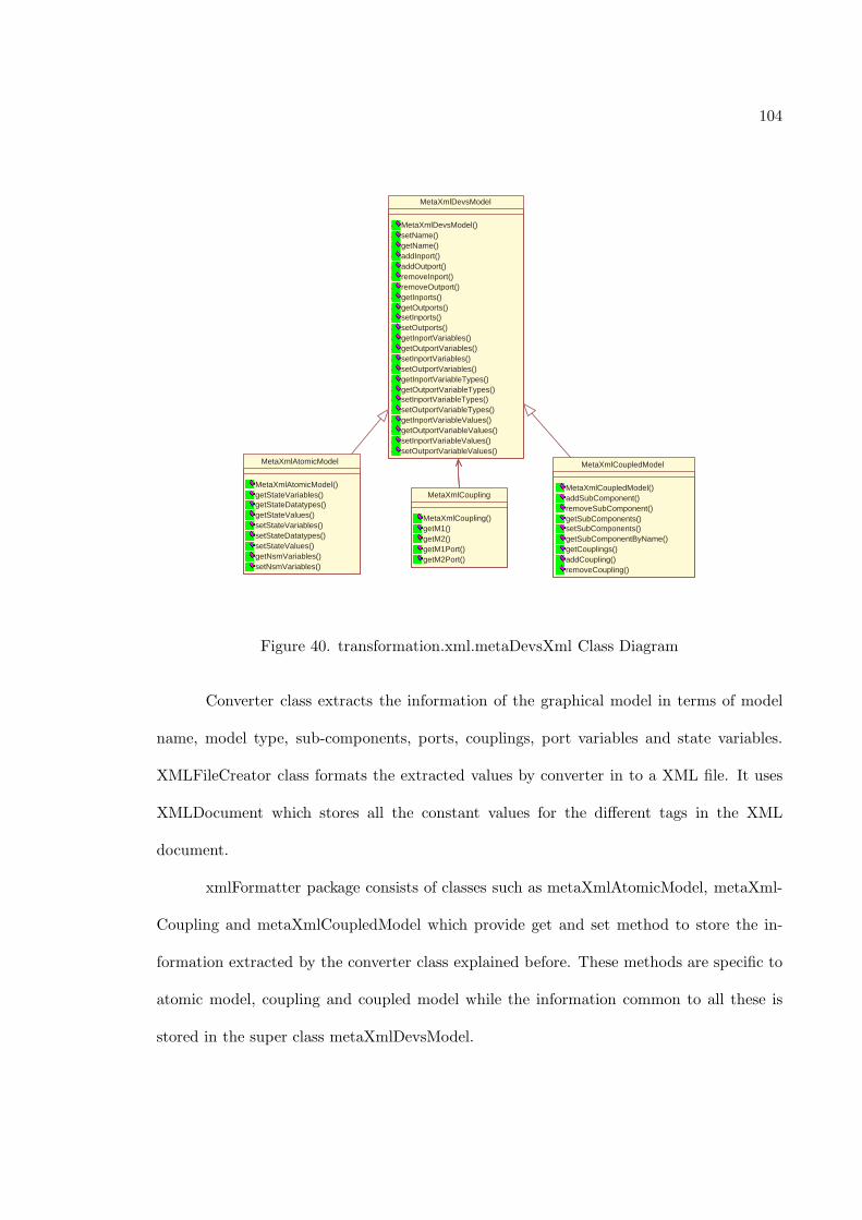
104
MetaXmlAtomicModel
MetaXmlAtomicModel() getStateVariables() getStateDatatypes() getStateValues() setStateVariables() setStateDatatypes() setStateValues() getNsmVariables() setNsmVariables()
MetaXmlCoupledModel
MetaXmlCoupledModel() addSubComponent() removeSubComponent() getSubComponents() setSubComponents() getSubComponentByName() getCouplings() addCoupling() removeCoupling()
MetaXmlCoupling
MetaXmlCoupling() getM1() getM2() getM1Port() getM2Port()
MetaXmlDevsModel
MetaXmlDevsModel() setName() getName() addInport() addOutport() removeInport() removeOutport() getInports() getOutports() setInports() setOutports() getInportVariables() getOutportVariables() setInportVariables() setOutportVariables() getInportVariableTypes() getOutportVariableTypes() setInportVariableTypes() setOutportVariableTypes() getInportVariableValues() getOutportVariableValues() setInportVariableValues() setOutportVariableValues()
Figure 40. transformation.xml.metaDevsXml Class Diagram
Converter class extracts the information of the graphical model in terms of model
name, model type, sub-components, ports, couplings, port variables and state variables.
XMLFileCreator class formats the extracted values by converter in to a XML file. It uses
XMLDocument which stores all the constant values for the different tags in the XML
document.
xmlFormatter package consists of classes such as metaXmlAtomicModel, metaXml-
Coupling and metaXmlCoupledModel which provide get and set method to store the in-
formation extracted by the converter class explained before. These methods are specific to
atomic model, coupling and coupled model while the information common to all these is
stored in the super class metaXmlDevsModel.
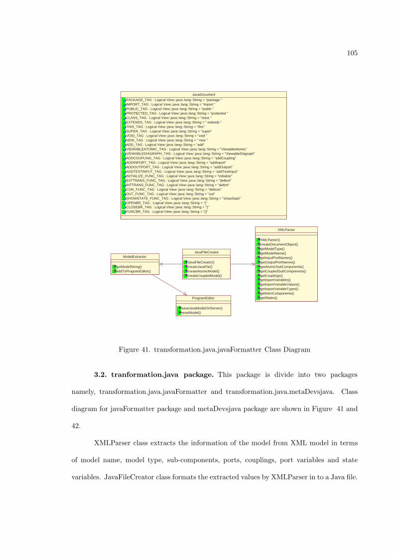
105
ProgramEditor
saveJavaModelOnServer() resetModel()
JavaDocument
PACKAGE_TAG : Logical View::java::lang::String = "package " IMPORT_TAG : Logical View::java::lang::String = "import " PUBLIC_TAG : Logical View::java::lang::String = "public " PROTECTED_TAG : Logical View::java::lang::String = "protected " CLASS_TAG : Logical View::java::lang::String = "class " EXTENDS_TAG : Logical View::java::lang::String = " extends " THIS_TAG : Logical View::java::lang::String = "this" SUPER_TAG : Logical View::java::lang::String = "super" VOID_TAG : Logical View::java::lang::String = "void " NEW_TAG : Logical View::java::lang::String = " new " ADD_TAG : Logical View::java::lang::String = "add" VIEWABLEATOMIC_TAG : Logical View::java::lang::String = "ViewableAtomic" VIEWABLEDIAGRAPH_TAG : Logical View::java::lang::String = "ViewableDiagraph" ADDCOUPLING_TAG : Logical View::java::lang::String = "addCoupling" ADDINPORT_TAG : Logical View::java::lang::String = "addInport" ADDOUTPORT_TAG : Logical View::java::lang::String = "addOutport" ADDTESTINPUT_TAG : Logical View::java::lang::String = "addTestInput" INITIALIZE_FUNC_TAG : Logical View::java::lang::String = "initialize" EXTTRANS_FUNC_TAG : Logical View::java::lang::String = "deltext" INTTRANS_FUNC_TAG : Logical View::java::lang::String = "deltint" CON_FUNC_TAG : Logical View::java::lang::String = "deltcon" OUT_FUNC_TAG : Logical View::java::lang::String = "out" SHOWSTATE_FUNC_TAG : Logical View::java::lang::String = "showState" OPENBR_TAG : Logical View::java::lang::String = "{" CLOSEBR_TAG : Logical View::java::lang::String = "}" FUNCBR_TAG : Logical View::java::lang::String = "()"
XMLParser
XMLParser() createDocumentObject() getModelType() getModelName() getInputPortNames() getOutputPortNames() getAtomicSubComponents() getCoupledSubComponents() getCouplings() getInportVariables() getInportVariableValues() getInportVariableTypes() getNsmComponents() getStates()
JavaFileCreator
JavaFileCreator() createJavaFile() createAtomicModel() createCoupledModel()
ModelExtractor
getModelString() addToProgramEditor()
Figure 41. transformation.java.javaFormatter Class Diagram
3.2. tranformation.java package. This package is divide into two packages
namely, transformation.java.javaFormatter and transformation.java.metaDevsjava. Class
diagram for javaFormatter package and metaDevsjava package are shown in Figure 41 and
42.
XMLParser class extracts the information of the model from XML model in terms
of model name, model type, sub-components, ports, couplings, port variables and state
variables. JavaFileCreator class formats the extracted values by XMLParser in to a Java file.
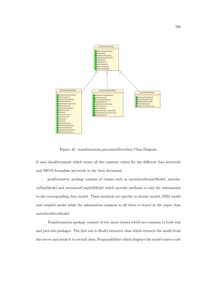
106
MetaJavaAtomicModel
MetaJavaAtomicModel() getClassName() getJavaModelString() addModelName()
addDefaultConstructor() addConstructor() addProcessingTime() addFunctions() initFunc()
extTransFunc() intTransFunc() confFunc() outFunc() showStateFunc() addNsmDeclaration()
addNsmDefinition() addStatesDeclaration() addStatesDefinition()
MetaJavaCoupledModel
MetaJavaCoupledModel()
getClassName() getJavaModelString() addModelName() addDefaultConstructor() addConstructor() addCouplings()
addAtomicSubComponents() addCoupledSubComponents() getObjectName()
MetaJavaDevsModel
MetaJavaDevsModel() addHeader()
addDefaultPackage() addImportStatements() addInports() addOutports() addTestInputs()
getCurrentDate() incrementIndent()
MetaJavaNsmModel
MetaJavaNsmModel() getJavaModelString() addDefaultPackage()
addModelName() addDefaultConstructor()
Figure 42. transformation.java.metaDevsJava Class Diagram
It uses JavaDocument which stores all the constant values for the different Java keywords
and DEVS formalism keywords in the Java document.
javaFormatter package consists of classes such as metaJavaAtomicModel, metaJa-
vaNsmModel and metaJavaCoupledModel which provide methods to add the information
to the corresponding Java model. These methods are specific to atomic model, NSM model
and coupled model while the information common to all these is stored in the super class
metaJavaDevsModel.
Transformation package consists of two more classes which are common to both xml
and java sub-packages. The first one is Model extractor class which extracts the model from
the server and sends it to second class, ProgramEditor which displays the model source code
107
to the user. It uses an external class Colorer which colors the source code shown by the
program editor at run time.
4. Re-factoring SESM Client/Server Communication
The design of a software environment such as SESM needs to account for require-
ments such as performance and usability. Performance refers to the systems responsiveness,
either the speed at which the computer operates by counting the operations (instructions)
performed or the total effectiveness of the computer system including throughput and re-
sponse time. Since communication may take longer than the computation, performance is
often a function of communication/interaction between the components [Bass98]. This is es-
pecially true in case of distributed and collaborative modeling environments where we need
to account for communication as well as network constraints such as bandwidth, delays,
etc. Therefore, in order to keep the response time or the availability of the system con-
stant, we need to ensure that the system performance is acceptable given particular network
configurations. Similar to performance, usability of a system such as SESM is important
for demanding tasks such as modeling. That is, the extended SESM environment not only
needs to be functionally correct, but also simplify (e.g., hide low-level details and provide
appropriate abstractions) user activities. These capabilities, therefore, are important to be
accounted for in the SESM software architecture specification.
The performance of the SESM degrades rapidly as the size of the model repository
increases. Since the architecture of SESM is client/server, the response time is affected not
only by carrying out model operations (e.g., adding a port), but also by communication
between the client and server. The current communication model requires retrieving the
entire model for every change that is made to the model. Lack of efficient communication
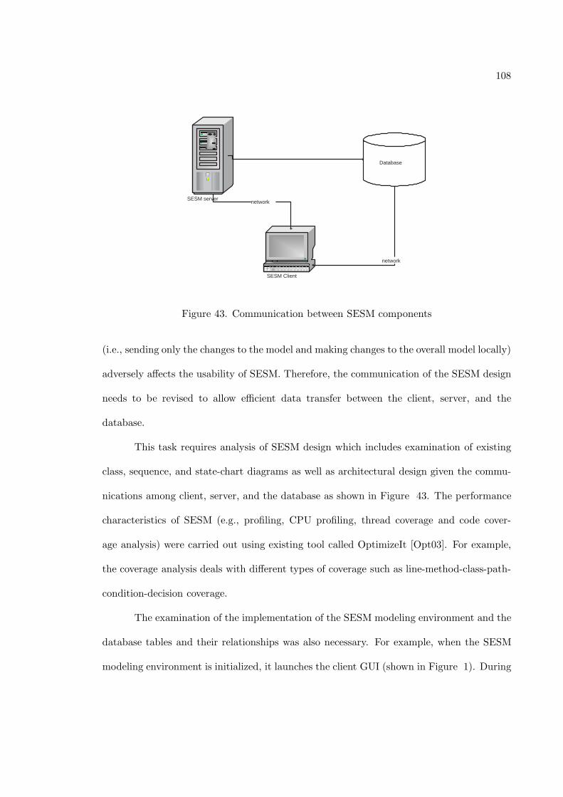
108
SESM server
SESM Client
Database
network
network
Figure 43. Communication between SESM components
(i.e., sending only the changes to the model and making changes to the overall model locally)
adversely affects the usability of SESM. Therefore, the communication of the SESM design
needs to be revised to allow efficient data transfer between the client, server, and the
database.
This task requires analysis of SESM design which includes examination of existing
class, sequence, and state-chart diagrams as well as architectural design given the commu-
nications among client, server, and the database as shown in Figure 43. The performance
characteristics of SESM (e.g., profiling, CPU profiling, thread coverage and code cover-
age analysis) were carried out using existing tool called OptimizeIt [Opt03]. For example,
the coverage analysis deals with different types of coverage such as line-method-class-path-
condition-decision coverage.
The examination of the implementation of the SESM modeling environment and the
database tables and their relationships was also necessary. For example, when the SESM
modeling environment is initialized, it launches the client GUI (shown in Figure 1). During
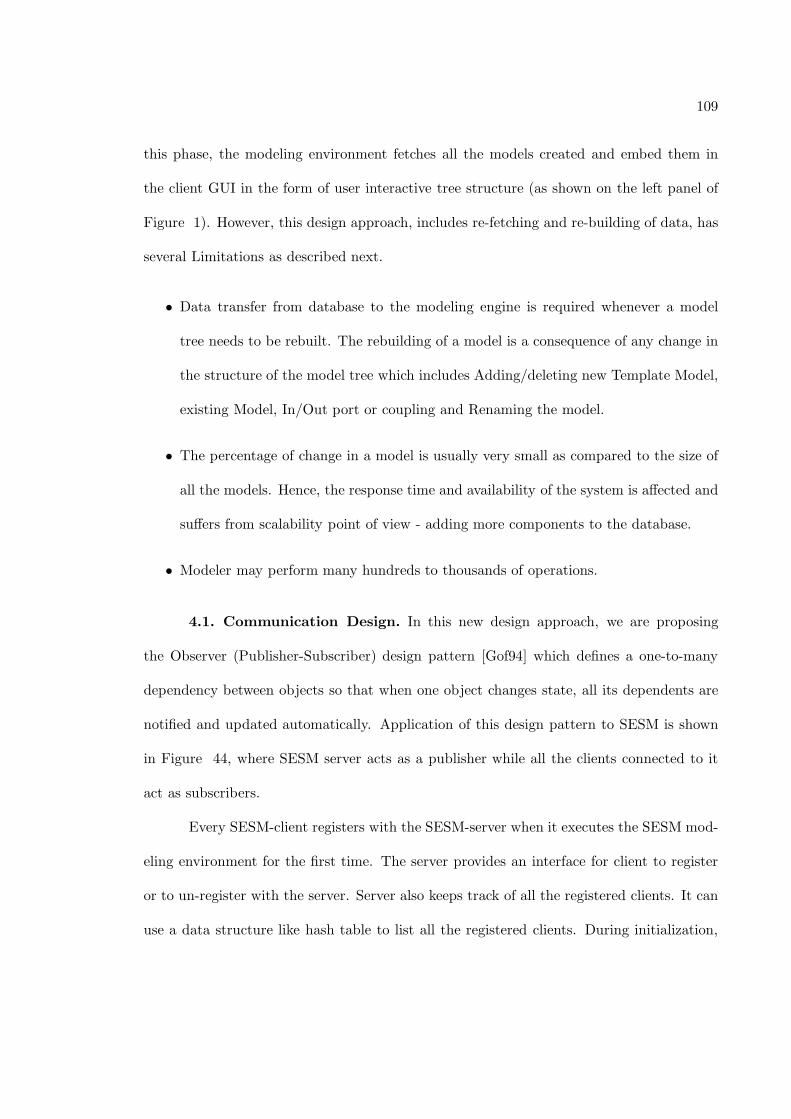
109
this phase, the modeling environment fetches all the models created and embed them in
the client GUI in the form of user interactive tree structure (as shown on the left panel of
Figure 1). However, this design approach, includes re-fetching and re-building of data, has
several Limitations as described next.
• Data transfer from database to the modeling engine is required whenever a model
tree needs to be rebuilt. The rebuilding of a model is a consequence of any change in
the structure of the model tree which includes Adding/deleting new Template Model,
existing Model, In/Out port or coupling and Renaming the model.
• The percentage of change in a model is usually very small as compared to the size of
all the models. Hence, the response time and availability of the system is affected and
suffers from scalability point of view - adding more components to the database.
• Modeler may perform many hundreds to thousands of operations.
4.1. Communication Design. In this new design approach, we are proposing
the Observer (Publisher-Subscriber) design pattern [Gof94] which defines a one-to-many
dependency between objects so that when one object changes state, all its dependents are
notified and updated automatically. Application of this design pattern to SESM is shown
in Figure 44, where SESM server acts as a publisher while all the clients connected to it
act as subscribers.
Every SESM-client registers with the SESM-server when it executes the SESM mod-
eling environment for the first time. The server provides an interface for client to register
or to un-register with the server. Server also keeps track of all the registered clients. It can
use a data structure like hash table to list all the registered clients. During initialization,
110
SESM server
SESM Client
Database
network
JDBC API
SESM Client SESM Client SESM Client
network
Local copy Local copy Local copy Local copy
Figure 44. Publisher-Subscriber Pattern
the client will fetch all the models from the server and save it locally in the form of a data
structure like Vector or ArrayList of models. This is a local copy of the data for client.
When the client makes any change to the model, corresponding event is generated
and sent to the server for validation. Server maintains the first-in-first-out queue to order
the request events received from all the registered clients. If the change is valid, server
updates the database and sends a notification to all the active clients. This notification is
also an event containing the entire information about the change. Once the client receives
this notification event, it will check the model hierarchy to find the applicability of that
change and make changes in the local copy. After updating the local copy with the latest
change, the client will refresh the entire tree model in the client GUI as before, but this
time it takes data from the local copy rather than fetching it from the database. The client
also maintains the queue to store the notifications received from the server. The advantages
of the proposed changes are

111
• Eliminating unnecessary data transfer between the application and the database and
• Loose coupling between client and server and thus higher degree of reusability.
CHAPTER 6
IMPLEMENTATION AND DEMONSTRATION
Implementation of the extended features in the SESM modeling environment pro-
totype is carried out using some of the technologies used for the previous version of the
SESM/CM such as Java programming language and MS-Access database. The additional
technology used in this research is eXtensive Markup Language (XML).
1. Approach And Tools
1.1. Meta-Modeling. XML [XML04] is a markup language that is used to aid
exchange of the data between applications, systems, businesses and over the web. It is an
excellent tool for carrying out transactions. With XML, one can define the data structures
and make them platform independent. XML is different than HTML as it is self-describing,
easily readable and it allows user to create his own tags and is not dependent on the
predefined tags.
In this research, we use XML for model transformation. The models (Atomic and
Coupled) that are stored in the database and represented to the user in the graphical format
need to be transformed in to the simulatable format and stored on a server so that it can
be simulated and validated. We chose XML for the following reasons
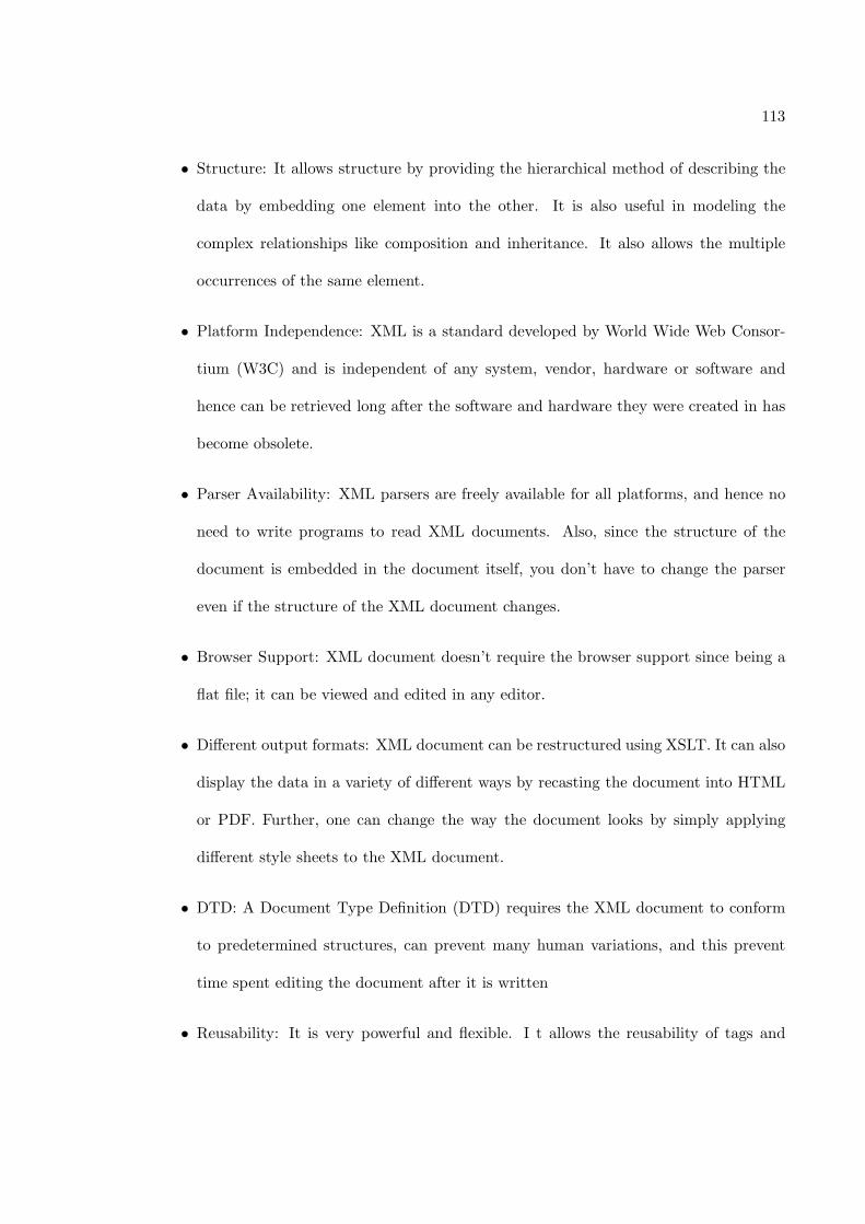
113
• Structure: It allows structure by providing the hierarchical method of describing the
data by embedding one element into the other. It is also useful in modeling the
complex relationships like composition and inheritance. It also allows the multiple
occurrences of the same element.
• Platform Independence: XML is a standard developed by World Wide Web Consor-
tium (W3C) and is independent of any system, vendor, hardware or software and
hence can be retrieved long after the software and hardware they were created in has
become obsolete.
• Parser Availability: XML parsers are freely available for all platforms, and hence no
need to write programs to read XML documents. Also, since the structure of the
document is embedded in the document itself, you don’t have to change the parser
even if the structure of the XML document changes.
• Browser Support: XML document doesn’t require the browser support since being a
flat file; it can be viewed and edited in any editor.
• Different output formats: XML document can be restructured using XSLT. It can also
display the data in a variety of different ways by recasting the document into HTML
or PDF. Further, one can change the way the document looks by simply applying
different style sheets to the XML document.
• DTD: A Document Type Definition (DTD) requires the XML document to conform
to predetermined structures, can prevent many human variations, and this prevent
time spent editing the document after it is written
• Reusability: It is very powerful and flexible. I t allows the reusability of tags and
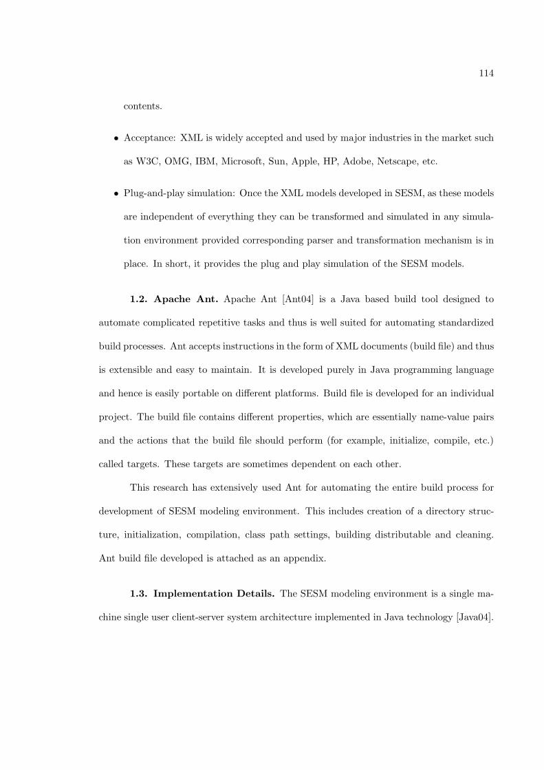
114
contents.
• Acceptance: XML is widely accepted and used by major industries in the market such
as W3C, OMG, IBM, Microsoft, Sun, Apple, HP, Adobe, Netscape, etc.
• Plug-and-play simulation: Once the XML models developed in SESM, as these models
are independent of everything they can be transformed and simulated in any simula-
tion environment provided corresponding parser and transformation mechanism is in
place. In short, it provides the plug and play simulation of the SESM models.
1.2. Apache Ant. Apache Ant [Ant04] is a Java based build tool designed to
automate complicated repetitive tasks and thus is well suited for automating standardized
build processes. Ant accepts instructions in the form of XML documents (build file) and thus
is extensible and easy to maintain. It is developed purely in Java programming language
and hence is easily portable on different platforms. Build file is developed for an individual
project. The build file contains different properties, which are essentially name-value pairs
and the actions that the build file should perform (for example, initialize, compile, etc.)
called targets. These targets are sometimes dependent on each other.
This research has extensively used Ant for automating the entire build process for
development of SESM modeling environment. This includes creation of a directory struc-
ture, initialization, compilation, class path settings, building distributable and cleaning.
Ant build file developed is attached as an appendix.
1.3. Implementation Details. The SESM modeling environment is a single ma-
chine single user client-server system architecture implemented in Java technology [Java04].
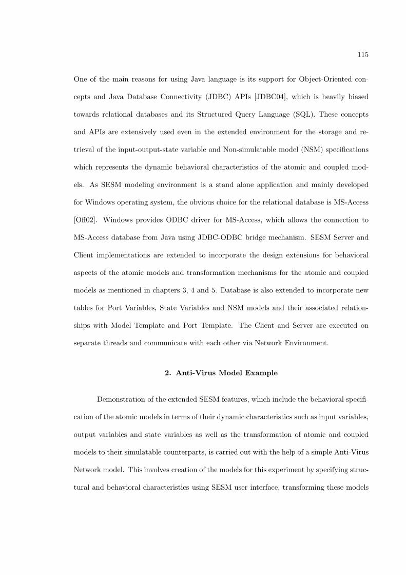
115
One of the main reasons for using Java language is its support for Object-Oriented con-
cepts and Java Database Connectivity (JDBC) APIs [JDBC04], which is heavily biased
towards relational databases and its Structured Query Language (SQL). These concepts
and APIs are extensively used even in the extended environment for the storage and re-
trieval of the input-output-state variable and Non-simulatable model (NSM) specifications
which represents the dynamic behavioral characteristics of the atomic and coupled mod-
els. As SESM modeling environment is a stand alone application and mainly developed
for Windows operating system, the obvious choice for the relational database is MS-Access
[Off02]. Windows provides ODBC driver for MS-Access, which allows the connection to
MS-Access database from Java using JDBC-ODBC bridge mechanism. SESM Server and
Client implementations are extended to incorporate the design extensions for behavioral
aspects of the atomic models and transformation mechanisms for the atomic and coupled
models as mentioned in chapters 3, 4 and 5. Database is also extended to incorporate new
tables for Port Variables, State Variables and NSM models and their associated relation-
ships with Model Template and Port Template. The Client and Server are executed on
separate threads and communicate with each other via Network Environment.
2. Anti-Virus Model Example
Demonstration of the extended SESM features, which include the behavioral specifi-
cation of the atomic models in terms of their dynamic characteristics such as input variables,
output variables and state variables as well as the transformation of atomic and coupled
models to their simulatable counterparts, is carried out with the help of a simple Anti-Virus
Network model. This involves creation of the models for this experiment by specifying struc-
tural and behavioral characteristics using SESM user interface, transforming these models
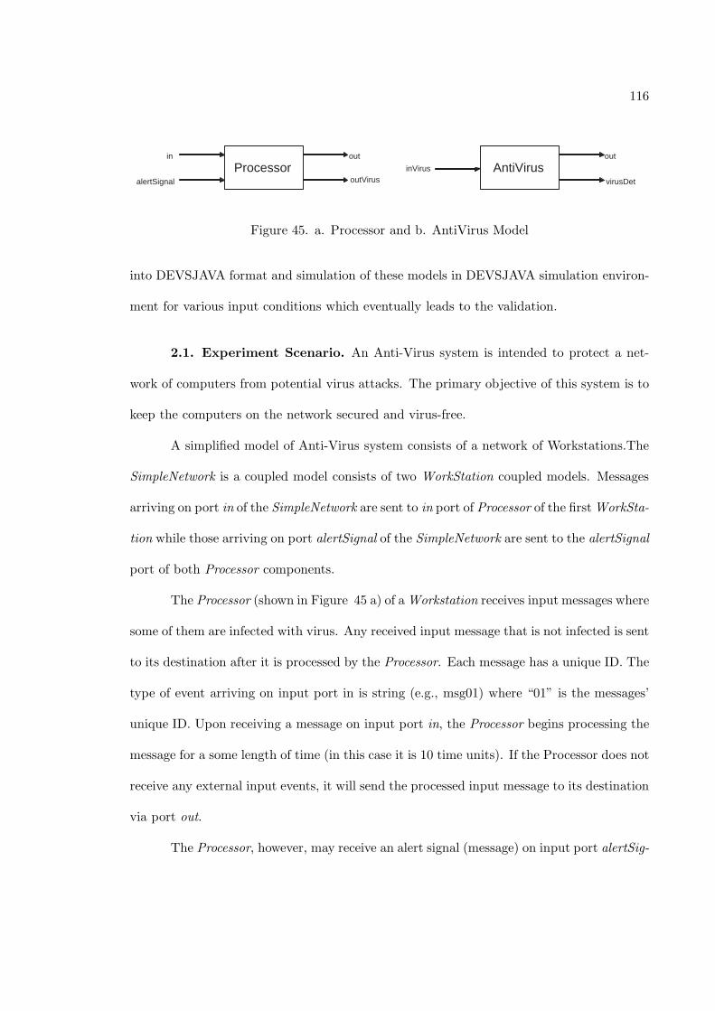
116
Processor AntiVirus in
alertSignal
out
outVirus inVirus
out
virusDet
Figure 45. a. Processor and b. AntiVirus Model
into DEVSJAVA format and simulation of these models in DEVSJAVA simulation environ-
ment for various input conditions which eventually leads to the validation.
2.1. Experiment Scenario. An Anti-Virus system is intended to protect a net-
work of computers from potential virus attacks. The primary objective of this system is to
keep the computers on the network secured and virus-free.
A simplified model of Anti-Virus system consists of a network of Workstations.The
SimpleNetwork is a coupled model consists of two WorkStation coupled models. Messages
arriving on port in of the SimpleNetwork are sent to in port of Processor of the first WorkSta-
tion while those arriving on port alertSignal of the SimpleNetwork are sent to the alertSignal
port of both Processor components.
The Processor (shown in Figure 45 a) of a Workstation receives input messages where
some of them are infected with virus. Any received input message that is not infected is sent
to its destination after it is processed by the Processor. Each message has a unique ID. The
type of event arriving on input port in is string (e.g., msg01) where “01” is the messages’
unique ID. Upon receiving a message on input port in, the Processor begins processing the
message for a some length of time (in this case it is 10 time units). If the Processor does not
receive any external input events, it will send the processed input message to its destination
via port out.
The Processor, however, may receive an alert signal (message) on input port alertSig-
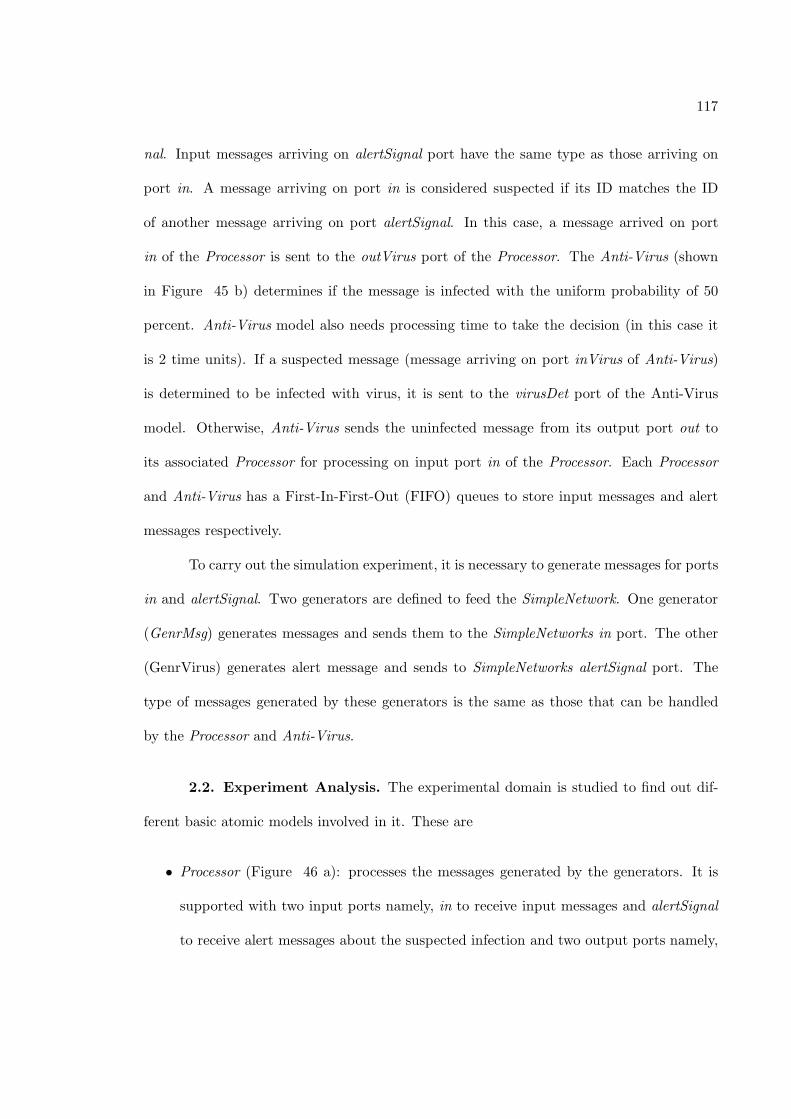
117
nal. Input messages arriving on alertSignal port have the same type as those arriving on
port in. A message arriving on port in is considered suspected if its ID matches the ID
of another message arriving on port alertSignal. In this case, a message arrived on port
in of the Processor is sent to the outVirus port of the Processor. The Anti-Virus (shown
in Figure 45 b) determines if the message is infected with the uniform probability of 50
percent. Anti-Virus model also needs processing time to take the decision (in this case it
is 2 time units). If a suspected message (message arriving on port inVirus of Anti-Virus)
is determined to be infected with virus, it is sent to the virusDet port of the Anti-Virus
model. Otherwise, Anti-Virus sends the uninfected message from its output port out to
its associated Processor for processing on input port in of the Processor. Each Processor
and Anti-Virus has a First-In-First-Out (FIFO) queues to store input messages and alert
messages respectively.
To carry out the simulation experiment, it is necessary to generate messages for ports
in and alertSignal. Two generators are defined to feed the SimpleNetwork. One generator
(GenrMsg) generates messages and sends them to the SimpleNetworks in port. The other
(GenrVirus) generates alert message and sends to SimpleNetworks alertSignal port. The
type of messages generated by these generators is the same as those that can be handled
by the Processor and Anti-Virus.
2.2. Experiment Analysis. The experimental domain is studied to find out dif-
ferent basic atomic models involved in it. These are
• Processor (Figure 46 a): processes the messages generated by the generators. It is
supported with two input ports namely, in to receive input messages and alertSignal
to receive alert messages about the suspected infection and two output ports namely,
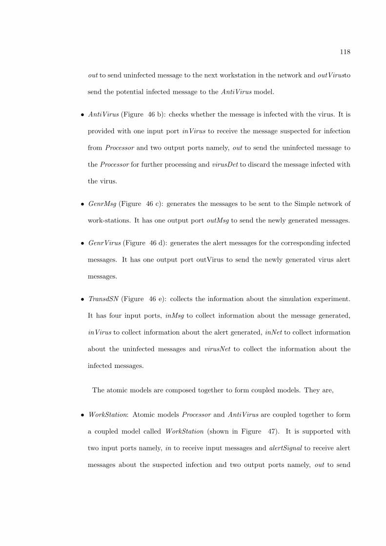
118
out to send uninfected message to the next workstation in the network and outVirusto
send the potential infected message to the AntiVirus model.
• AntiVirus (Figure 46 b): checks whether the message is infected with the virus. It is
provided with one input port inVirus to receive the message suspected for infection
from Processor and two output ports namely, out to send the uninfected message to
the Processor for further processing and virusDet to discard the message infected with
the virus.
• GenrMsg (Figure 46 c): generates the messages to be sent to the Simple network of
work-stations. It has one output port outMsg to send the newly generated messages.
• GenrVirus (Figure 46 d): generates the alert messages for the corresponding infected
messages. It has one output port outVirus to send the newly generated virus alert
messages.
• TransdSN (Figure 46 e): collects the information about the simulation experiment.
It has four input ports, inMsg to collect information about the message generated,
inVirus to collect information about the alert generated, inNet to collect information
about the uninfected messages and virusNet to collect the information about the
infected messages.
The atomic models are composed together to form coupled models. They are,
• WorkStation: Atomic models Processor and AntiVirus are coupled together to form
a coupled model called WorkStation (shown in Figure 47). It is supported with
two input ports namely, in to receive input messages and alertSignal to receive alert
messages about the suspected infection and two output ports namely, out to send
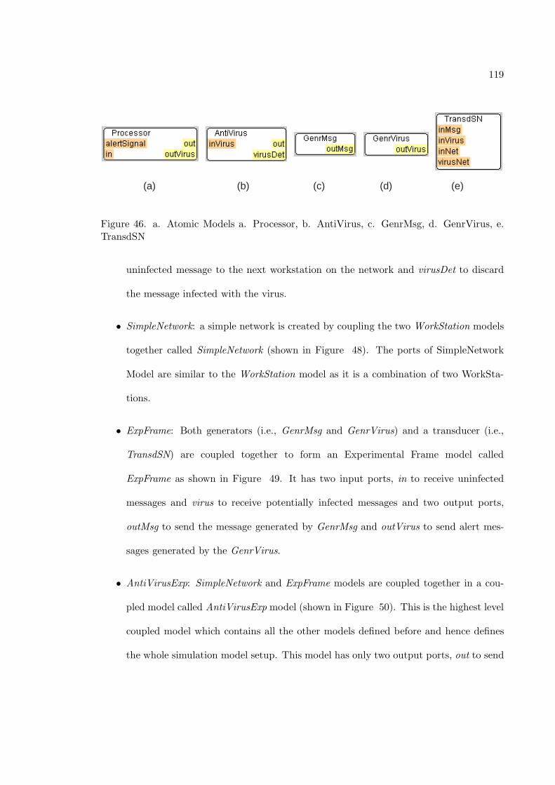
119
(a) (b) (c) (d) (e)
Figure 46. a. Atomic Models a. Processor, b. AntiVirus, c. GenrMsg, d. GenrVirus, e.TransdSN
uninfected message to the next workstation on the network and virusDet to discard
the message infected with the virus.
• SimpleNetwork: a simple network is created by coupling the two WorkStation models
together called SimpleNetwork (shown in Figure 48). The ports of SimpleNetwork
Model are similar to the WorkStation model as it is a combination of two WorkSta-
tions.
• ExpFrame: Both generators (i.e., GenrMsg and GenrVirus) and a transducer (i.e.,
TransdSN) are coupled together to form an Experimental Frame model called
ExpFrame as shown in Figure 49. It has two input ports, in to receive uninfected
messages and virus to receive potentially infected messages and two output ports,
outMsg to send the message generated by GenrMsg and outVirus to send alert mes-
sages generated by the GenrVirus.
• AntiVirusExp: SimpleNetwork and ExpFrame models are coupled together in a cou-
pled model called AntiVirusExp model (shown in Figure 50). This is the highest level
coupled model which contains all the other models defined before and hence defines
the whole simulation model setup. This model has only two output ports, out to send
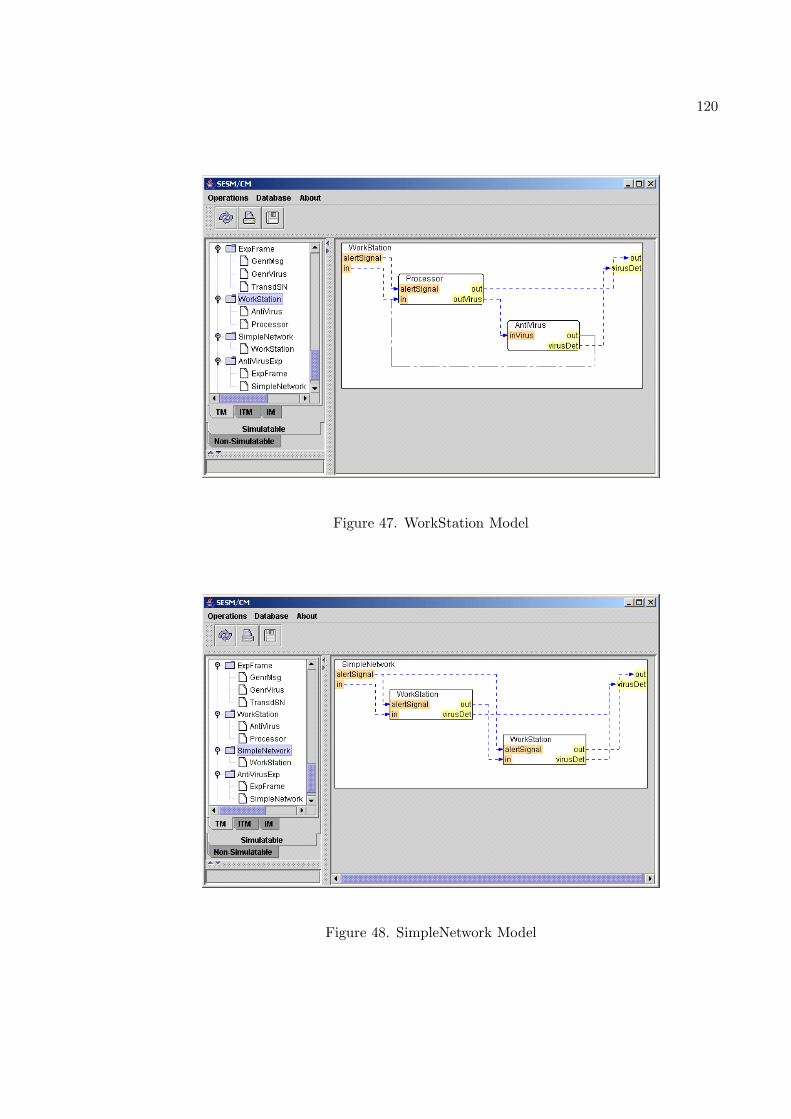
120
Figure 47. WorkStation Model
Figure 48. SimpleNetwork Model
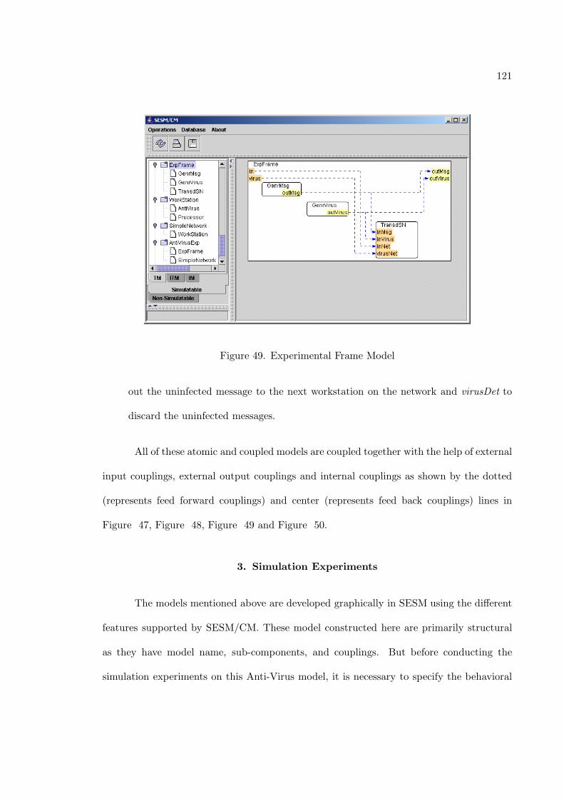
121
Figure 49. Experimental Frame Model
out the uninfected message to the next workstation on the network and virusDet to
discard the uninfected messages.
All of these atomic and coupled models are coupled together with the help of external
input couplings, external output couplings and internal couplings as shown by the dotted
(represents feed forward couplings) and center (represents feed back couplings) lines in
Figure 47, Figure 48, Figure 49 and Figure 50.
3. Simulation Experiments
The models mentioned above are developed graphically in SESM using the different
features supported by SESM/CM. These model constructed here are primarily structural
as they have model name, sub-components, and couplings. But before conducting the
simulation experiments on this Anti-Virus model, it is necessary to specify the behavioral
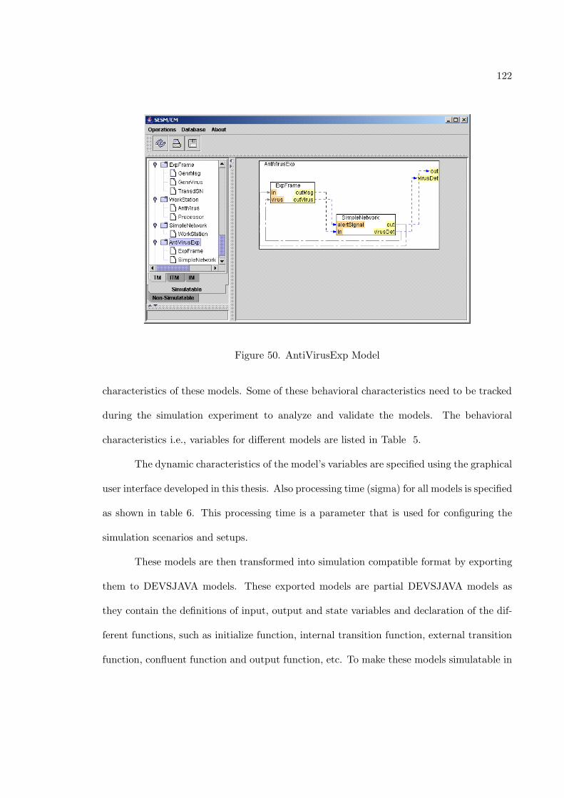
122
Figure 50. AntiVirusExp Model
characteristics of these models. Some of these behavioral characteristics need to be tracked
during the simulation experiment to analyze and validate the models. The behavioral
characteristics i.e., variables for different models are listed in Table 5.
The dynamic characteristics of the model’s variables are specified using the graphical
user interface developed in this thesis. Also processing time (sigma) for all models is specified
as shown in table 6. This processing time is a parameter that is used for configuring the
simulation scenarios and setups.
These models are then transformed into simulation compatible format by exporting
them to DEVSJAVA models. These exported models are partial DEVSJAVA models as
they contain the definitions of input, output and state variables and declaration of the dif-
ferent functions, such as initialize function, internal transition function, external transition
function, confluent function and output function, etc. To make these models simulatable in
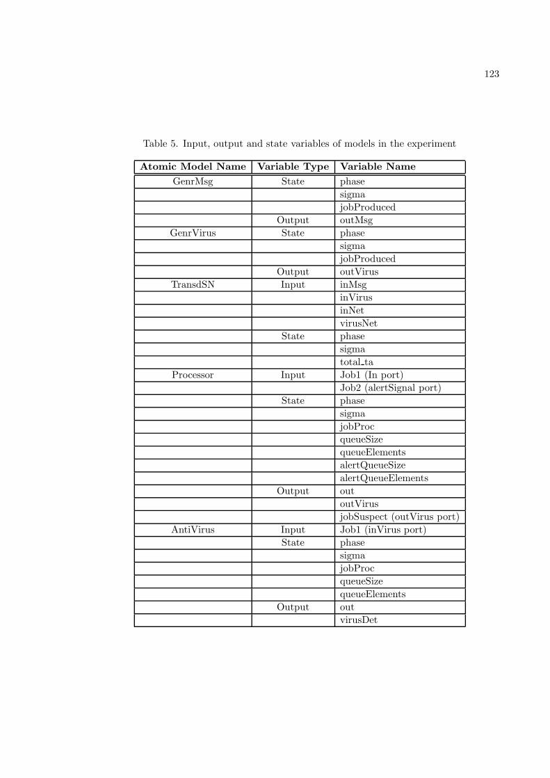
123
Table 5. Input, output and state variables of models in the experiment
Atomic Model Name Variable Type Variable Name
GenrMsg State phase
sigma
jobProduced
Output outMsg
GenrVirus State phase
sigma
jobProduced
Output outVirus
TransdSN Input inMsg
inVirus
inNet
virusNet
State phase
sigma
total ta
Processor Input Job1 (In port)
Job2 (alertSignal port)
State phase
sigma
jobProc
queueSize
queueElements
alertQueueSize
alertQueueElements
Output out
outVirus
jobSuspect (outVirus port)
AntiVirus Input Job1 (inVirus port)
State phase
sigma
jobProc
queueSize
queueElements
Output out
virusDet
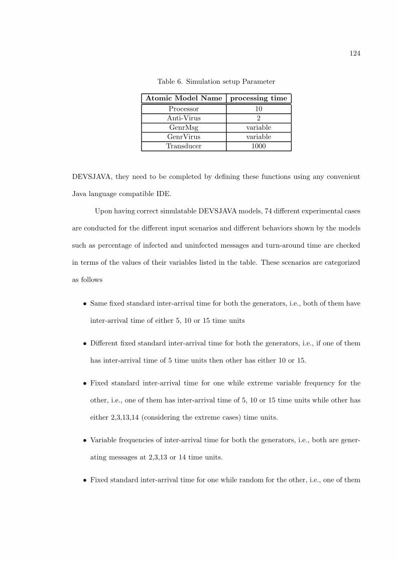
124
Table 6. Simulation setup Parameter
Atomic Model Name processing time
Processor 10
Anti-Virus 2
GenrMsg variable
GenrVirus variable
Transducer 1000
DEVSJAVA, they need to be completed by defining these functions using any convenient
Java language compatible IDE.
Upon having correct simulatable DEVSJAVA models, 74 different experimental cases
are conducted for the different input scenarios and different behaviors shown by the models
such as percentage of infected and uninfected messages and turn-around time are checked
in terms of the values of their variables listed in the table. These scenarios are categorized
as follows
• Same fixed standard inter-arrival time for both the generators, i.e., both of them have
inter-arrival time of either 5, 10 or 15 time units
• Different fixed standard inter-arrival time for both the generators, i.e., if one of them
has inter-arrival time of 5 time units then other has either 10 or 15.
• Fixed standard inter-arrival time for one while extreme variable frequency for the
other, i.e., one of them has inter-arrival time of 5, 10 or 15 time units while other has
either 2,3,13,14 (considering the extreme cases) time units.
• Variable frequencies of inter-arrival time for both the generators, i.e., both are gener-
ating messages at 2,3,13 or 14 time units.
• Fixed standard inter-arrival time for one while random for the other, i.e., one of them
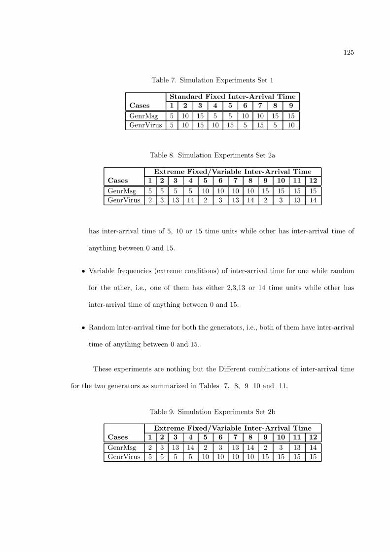
125
Table 7. Simulation Experiments Set 1
Standard Fixed Inter-Arrival TimeCases 1 2 3 4 5 6 7 8 9
GenrMsg 5 10 15 5 5 10 10 15 15
GenrVirus 5 10 15 10 15 5 15 5 10
Table 8. Simulation Experiments Set 2a
Extreme Fixed/Variable Inter-Arrival TimeCases 1 2 3 4 5 6 7 8 9 10 11 12
GenrMsg 5 5 5 5 10 10 10 10 15 15 15 15
GenrVirus 2 3 13 14 2 3 13 14 2 3 13 14
has inter-arrival time of 5, 10 or 15 time units while other has inter-arrival time of
anything between 0 and 15.
• Variable frequencies (extreme conditions) of inter-arrival time for one while random
for the other, i.e., one of them has either 2,3,13 or 14 time units while other has
inter-arrival time of anything between 0 and 15.
• Random inter-arrival time for both the generators, i.e., both of them have inter-arrival
time of anything between 0 and 15.
These experiments are nothing but the Different combinations of inter-arrival time
for the two generators as summarized in Tables 7, 8, 9 10 and 11.
Table 9. Simulation Experiments Set 2b
Extreme Fixed/Variable Inter-Arrival TimeCases 1 2 3 4 5 6 7 8 9 10 11 12
GenrMsg 2 3 13 14 2 3 13 14 2 3 13 14
GenrVirus 5 5 5 5 10 10 10 10 15 15 15 15
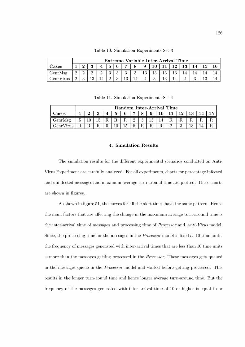
126
Table 10. Simulation Experiments Set 3
Extreme Variable Inter-Arrival TimeCases 1 2 3 4 5 6 7 8 9 10 11 12 13 14 15 16
GenrMsg 2 2 2 2 3 3 3 3 13 13 13 13 14 14 14 14
GenrVirus 2 3 13 14 2 3 13 14 2 3 13 14 2 3 13 14
Table 11. Simulation Experiments Set 4
Random Inter-Arrival TimeCases 1 2 3 4 5 6 7 8 9 10 11 12 13 14 15
GenrMsg 5 10 15 R R R 2 3 13 14 R R R R R
GenrVirus R R R 5 10 15 R R R R 2 3 13 14 R
4. Simulation Results
The simulation results for the different experimental scenarios conducted on Anti-
Virus Experiment are carefully analyzed. For all experiments, charts for percentage infected
and uninfected messages and maximum average turn-around time are plotted. These charts
are shown in figures.
As shown in figure 51, the curves for all the alert times have the same pattern. Hence
the main factors that are affecting the change in the maximum average turn-around time is
the inter-arrival time of messages and processing time of Processor and Anti-Virus model.
Since, the processing time for the messages in the Processor model is fixed at 10 time units,
the frequency of messages generated with inter-arrival times that are less than 10 time units
is more than the messages getting processed in the Processor. These messages gets queued
in the messages queue in the Processor model and waited before getting processed. This
results in the longer turn-aound time and hence longer average turn-around time. But the
frequency of the messages generated with inter-arrival time of 10 or higher is equal to or
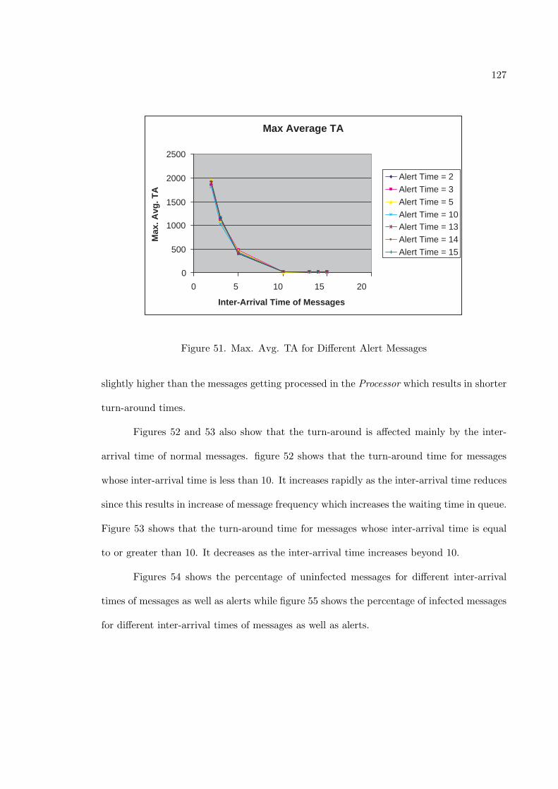
127
Max Average TA
0
500
1000
1500
2000
2500
0 5 10 15 20
Inter-Arrival Time of Messages
Max
. Avg
. TA
Alert Time = 2
Alert Time = 3
Alert Time = 5
Alert Time = 10 Alert Time = 13
Alert Time = 14
Alert Time = 15
Figure 51. Max. Avg. TA for Different Alert Messages
slightly higher than the messages getting processed in the Processor which results in shorter
turn-around times.
Figures 52 and 53 also show that the turn-around is affected mainly by the inter-
arrival time of normal messages. figure 52 shows that the turn-around time for messages
whose inter-arrival time is less than 10. It increases rapidly as the inter-arrival time reduces
since this results in increase of message frequency which increases the waiting time in queue.
Figure 53 shows that the turn-around time for messages whose inter-arrival time is equal
to or greater than 10. It decreases as the inter-arrival time increases beyond 10.
Figures 54 shows the percentage of uninfected messages for different inter-arrival
times of messages as well as alerts while figure 55 shows the percentage of infected messages
for different inter-arrival times of messages as well as alerts.
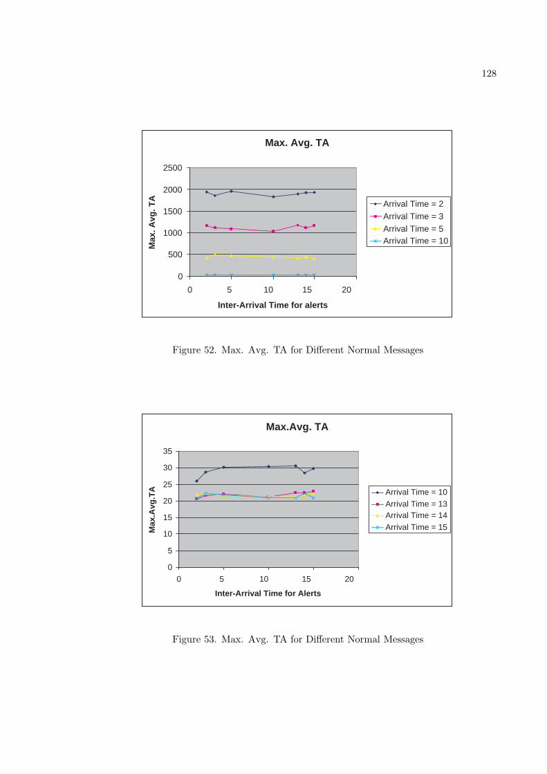
128
Max. Avg. TA
0
500
1000
1500
2000
2500
0 5 10 15 20
Inter-Arrival Time for alerts
Max
. Avg
. TA
Arrival Time = 2
Arrival Time = 3
Arrival Time = 5 Arrival Time = 10
Figure 52. Max. Avg. TA for Different Normal Messages
Max.Avg. TA
0
5
10
15
20
25
30
35
0 5 10 15 20
Inter-Arrival Time for Alerts
Max
.Avg
.TA
Arrival Time = 10
Arrival Time = 13 Arrival Time = 14
Arrival Time = 15
Figure 53. Max. Avg. TA for Different Normal Messages
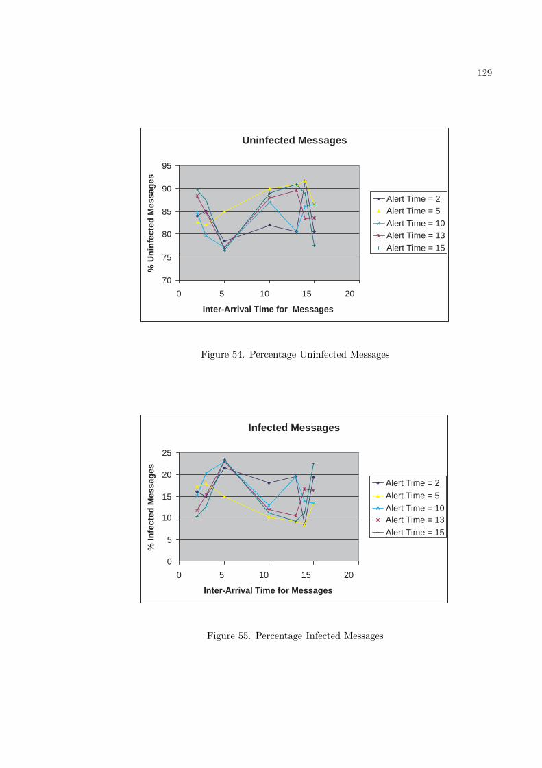
129
Uninfected Messages
70
75
80
85
90
95
0 5 10 15 20
Inter-Arrival Time for Messages
% U
nin
fect
ed M
essa
ges
Alert Time = 2 Alert Time = 5
Alert Time = 10 Alert Time = 13
Alert Time = 15
Figure 54. Percentage Uninfected Messages
Infected Messages
0
5
10
15
20
25
0 5 10 15 20
Inter-Arrival Time for Messages
% In
fect
ed M
essa
ges
Alert Time = 2
Alert Time = 5
Alert Time = 10 Alert Time = 13
Alert Time = 15
Figure 55. Percentage Infected Messages
CHAPTER 7
CONCLUSION AND FUTURE RESEARCH
1. Conclusion
Increase in the size of the system leads to the increase in the structural and behavioral
complexity of the system. Such complex systems are analyzed, designed and developed by
using modeling and simulation approach, This approach is based on principles of system
theory and object-orientation. Simulation model of a system is developed to study the
structural and behavioral complexity of the system over time. For this, modeler needs
to specify the model in terms of its structure and behavior and to make them persistent
to achieve model reusability. Therefore, the specification and the storage of structural
and behavioral aspects of the model are important to achieve the simulation, analysis and
validation of the model.
This research is primarily concerned with the specification of the behavioral aspects
of atomic models. It has used and extended the Scalable System Entity Structure Mod-
eler (SESM/CM) modeling environment. The software architecture of SESM is primarily
client-server type and is composed of four main components i.e., Client, Server, Network
Environment and RDBMS. This architecture offers simplicity and higher degree of modular
design and implementation. This architecture allows multiple clients and server to read
131
the data from RDBMS but only server has rights to write to it. Client and server interact
with each other via network environment. This research also used DEVSJAVA as a simu-
lation environment to demonstrate, test and validate atomic and coupled models which are
developed in extended SESM environment and transformed into simulation compatible for-
mat. This research described an extension of SESM/CM architecture to incorporate these
features, while retaining the overall architecture of the system.
It conceptualized the necessity and approach for capturing and storing behavioral
aspects of an atomic model in the relational database management system. These behavioral
aspects can be defined in terms of the dynamic characteristics of model such as input
variables, output variables and state variables. For this, the existing entity-relationship
diagram is extended (as shown in section 4.3) to support port variables (both input and
output), state variables and NSM models tables. These NSM models are essentially complex
data structures which act as a type of input, output or state variable. Furthermore, the
relationships between these tables and other tables such as Model Template, Port Template,
etc are also defined. The software design, analysis and implementation of the SESM/CM are
extended to accommodate the capturing of behavioral aspects and mapping of the object-
oriented models to their relational counterparts. This involves the extensions of client and
server modules in terms of capturing user inputs, transactions in SQL and modeling of
constraints using programming logic that cannot be expressed in E-R diagram or relational
model.
Second part of the research is concentrated on the transformation of atomic and cou-
pled models in to their simulatable counterparts to achieve their simulation and validation.
This involved the creation of new module for the transformation of the models stored in
the database into XML and DEVSJAVA models. These transformed models are stored on
132
the server as flat files at a specified location and retrieved back when required for viewing
or editing.
Extension of graphical user interface is an important aspect of this research. It
includes the redesign of the existing model menu to make it compatible with the system
formalism and addition of the menu items and corresponding user input dialogs to facilitate
the specification of the behavioral aspects, transformation of the models and viewing of
these transformed models and their metrics. It also added one more tree view for NSM
models, in addition to the existing model tree views for template models, instance template
models and instance models. This tree view has a functionality to add modelers own NSM
model and a capability to edit and save the existing NSM model.
These new features along with the existing features are demonstrated with the help
of Anti-virus model experiment. In this various models are created using SESM in terms of
structural and some of the behavioral features and then transformed into simulation com-
patible models. These transformed models are simulated against various input conditions
to test the behavioral changes of the overall system.
2. Future Research
This research partially specifies or measures the structural and behavioral aspects
of the atomic models. In order to achieve total structural and behavioral specification and
measurement, SESM needs to be extend in the following areas,
2.1. Computation of Additional Metrics. SESM/CM facilitates computation
of nine basic structural metrics - (Immediate Children, Total Children, Input Ports, Output
133
Ports, Total Ports, Internal Couplings, External Input Couplings, External Output Cou-
plings, Total Couplings). However, additional structural and behavioral metrics may be
obtained from the models. In structural metrics, higher-level metrics such as fan-in (the
number of couplings between an input port and many output ports) and fan-out (the num-
ber of couplings between an output port and many input ports) can be computed. Also
the present metrics compute the number of couplings at one level. This may be extended,
for example, to compute the total number of couplings of a component till its lowest level
of decomposition. In behavioral part, metrics in terms of input variables, output variables
and state variables can be computed.
2.2. Support for storage of State Transition of Atomic Models. This re-
search described the specification of some of the behavioral aspects of an atomic model. But
the behavior can be completely captures only when the state transition of atomic models is
specified. Therefore, this research can be further extended to support the specification of
the state transition of atomic models and their storage in the relational database system.
2.3. Transformation of State Transition to Functions. The detail procedure
of transformation of the models stored in the database into their simulation compatible
format to achieve their simulation and hence validation, is explained in this research. This
mechanism also can be extended to transform the state transition specification in the data-
base to their corresponding transition functions such as external transition function, internal
transition function, etc. in XML or Java model.
2.4. Transformation from Simulatable Model to Database Model. Trans-
formation of the models stored in the database to their simulatable counterparts is defined in
134
this research. This work can be extended to have a reverse mechanism to transform the ex-
isting simulatable model in to the database model to achieve reuse of these models instead of
recreating them in modeling engine and hence complete the Modeling-Simulation-Modeling
cycle.
2.5. User Interface Enhancements. User interface of SESM modeling environ-
ment can be further enhanced to have drag and drop as well as cut-copy-paste facilities to
speed up the modeling process as it will avoid the manual adding-deleting of the models
while creating the large hierarchical models.
REFERENCES
[acims04] Arizona Center for Integrative Modeling and Simulation (ACIMS) Software De-
velopment :http://www.acims.arizona.edu/SOFTWARE/software.shtml
[Ant04] Apache Ant: Java based build tool: http://ant.apache.org/
[Bass98] Bass L., Clemens P., Kazman R., Software Architecture in Practice, The SEI series
in Software Engineering, 1998, Addison-Wesley
[Bank01] Banks J., Carson J., Nelson B., Nicol D.; Discrete Event System Simulation; 3rd
Edition ed. 2001; Prentice Hall Inc.
[Boo94] Booch G., Object-Oriented Analysis and Design with Applications, 2nd Edition,
Cunning Benjamin, 1994.
[Boo99] Booch G., Rumbaugh J., Jacobson I.; The Unified Modeling Language Use Guide,
1st Edition, Pearson Education, 1999.
[Ext00] Extend Professional Simulation Tools, User guide version 5, edition 2000.
[Fow99] Fowler M., Scott K., UML Distilled: A Brief Guide to the Standard Object Modeling
Language, 2nd Edition, Addison-Wesley, August 20, 1999
[Fu02] Fu T. S., Hierarchical Modeling of Large-Scale Systems using Relational Databases,
Electrical and Computer Engineering, University of Arizona, Tucson, 2002.
136
[Gof94] Gamma E., Helm R., Johnson R. and Vlissides J, Design Patterns: Elements of
Reusable Object-Oriented Software; ISBN 0-201-63361-2
[Java04] Java Programming Language: http://java.sun.com
[JDBC04] Java Database Connectivity APIs http://java.sun.com/products/jdbc
[Kof03] Kofman, E. (2003); Discrete Event Based Simulation and Control of Continuous
Systems, University of de Rosario, Argentina
[Off02] Microsoft Access 2002: www.microsoft.com/office/access/default.asp
[Opt03] Borland OptimizeIt: Optimization tool; http://www.borland.com/optimizeit
[Sar02] Sarjoughian H. S., A Model for Design of Scalable Modeling of Modular, Hierar-
chical Systems, Internal Report, Computer Science and Engr. Dept., Arizona State
University, 2002.
[Sar03] Sarjoughian, H.S., Singh, R.K, Building Simulation Modeling Environments Using
Systems Theory and Software Architecture Principles, Advanced Simulation Technol-
ogy Conference, p. 99-104, April, Washington DC
[Sing04] Ranjit Singh, A Software Architecture Design for Discrete Event Simulation En-
vironments, Computer Science and Engineering, Arizona State University, fall 2004.
[Smo03] Mohan S., Measuring Structural Complexities of Modular Hierarchical Large Scale
Models, Computer Science and Engineering Department, Arizona State University,
2003
[Wym93] Wymore, A.W., Model-based Systems Engineering: An Introduction to the Math-
137
ematical Theory of Discrete Systems and to the Tricotyledon Theory of System Design,
1993, Boca Raton: CRC.
[XML04] eXtensible Markup Language: http://www.xml.org/
[Zei84] Zeigler B. P., Multi-facetted Modeling and Discrete Event Simulation, London: Aca-
demic Press, 1984
[Zei90] Zeigler B. P., Object Oriented Simulation with Hierarchical Modular Models: Intel-
ligent Agents and Endomorphic Systems, Academic Press: 1990
[Zei00] Zeigler, B.P., Praehofer H., Kim T.G., heory of Modeling and Simulation: Integrat-
ing Discrete Event and Continuous Complex Dynamic Systems. Second Edition ed.
2000: Academic Press.
[Zei03] Zeigler B. P., Sarjoughian H. S., Introduction to DEVS Modeling and Simulation
with JAVA: Developing Component-based Simulation Models, Sept 2003.