Embed Size (px)
Citation preview
June 1995 Behavioral Modeling 8-1
Table of Contents CloseMenus User Guide Go BackIndex 1 of 48
8Behavioral Modeling
The language constructs introduced so far allow hardware to be describedat a relatively detailed level. Modeling a circuit with logic gates andcontinuous assignments reflects quite closely the logic structure of thecircuit being modeled; however, these constructs do not provide the powerof abstraction necessary for describing complex high level aspects of asystem. The procedural constructs described in this chapter are well suitedto tackling problems such as describing a microprocessor or implementingcomplex timing checks.
This chapter covers the following topics:
■ Section 8.1 provides a brief overview of a behavioral model to providea context for understanding the behavioral constructs detailed in thischapter.
■ Section 8.2 discusses the two statements used to describe procedures(always andinitial ).
■ Section 8.3 discusses procedural assignment statements.
■ Section 8.4 describes conditional statements (if andif-else ).
■ Section 8.5 describes multi-way decision statements (if-else-ifandcase ).
■ Section 8.6 describes loop statements (forever , repeat , while , andfor ).
■ Section 8.7 discusses procedural timing controls.
■ Section 8.8 describes sequential block statements (begin-end ) andparallel block statements (fork-join ).
■ Section 8.9 contains two complete behavioral model examples thatillustrate the behavioral constructs introduced in this chapter.
Behavioral Model Overview
June 1995 Behavioral Modeling 8-2
Table of Contents CloseMenus User Guide Go BackIndex 2 of 48
8.1
Behavioral Model Overview
Verilog behavioral models contain procedural statements that control thesimulation and manipulate variables of the data types previouslydescribed. These statements are contained within procedures. Eachprocedure has an activity flow associated with it.
The activity starts at the control constructsinitial andalways . Eachinitial statement and eachalways statement starts a separate activityflow. All of the activity flows are concurrent, allowing you to model theinherent concurrence of hardware.
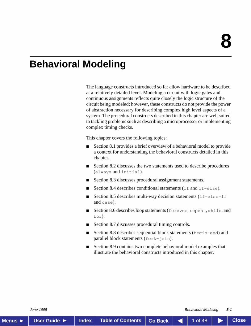
Example 8-1 is a complete Verilog behavioral model.
Example 8-1: Example of a behavioral model
During simulation of this model, all of the flows defined by theinitialandalways statements start together at simulation time zero. Theinitial statements execute once, and thealways statements executerepetitively.
module behave;reg [1:0]a,b;initial
begina = ’b1;b = ’b0;
endalways
begin#50 a = ~a;
endalways
begin#100 b = ~b;
endendmodule
Behavioral Model Overview
June 1995 Behavioral Modeling 8-3
Table of Contents CloseMenus User Guide Go BackIndex 3 of 48
In this model, the register variablesa andb initialize to binary 1 and 0respectively at simulation time zero. Theinitial statement is thencomplete and does not execute again during this simulation run. Thisinitial statement contains abegin-end block (also called a sequentialblock) of statements. In thisbegin-end block,a is initialized first,followed byb.
Thealways statements also start at time zero, but the values of thevariables do not change until the times specified by the delay controls(introduced by#) have gone by. Thus, registera inverts after 50 time units,and registerb inverts after 100 time units. Since thealways statementsrepeat, this model produces two square waves. Registera toggles with aperiod of 100 time units, and registerb toggles with a period of 200 timeunits. The twoalways statements proceed concurrently throughout theentire simulation run.
Structured Procedures
June 1995 Behavioral Modeling 8-4
Table of Contents CloseMenus User Guide Go BackIndex 4 of 48
8.2
Structured Procedures
All procedures in Verilog are specified within one of the following fourstatements:
■ always statement
■ initial statement
■ task
■ function
Tasks and functions are procedures that are enabled from one or moreplaces in other procedures. Tasks and functions are covered in detail inChapter 9,Tasks and Functions.
The initial andalways statements are enabled at the beginning ofsimulation. Theinitial statement executes only once and its activitydies when the statement has finished. Thealways statement executesrepeatedly. Its activity dies only when the simulation is terminated. Thereis no limit to the number ofinitial andalways blocks that can bedefined in a module.
8.2.1Thealways statement repeats continuously throughout the wholesimulation run. Syntax 8-1 shows the syntax for thealways statement.
Syntax 8-1: Syntax for always statement
Thealways statement, because of its looping nature, is only useful whenused in conjunction with some form of timing control. If analwaysstatement provides no means for time to advance, thealways statementcreates a simulation deadlock condition. The following code, for example,creates an infinite zero-delay loop:
always areg = ~areg;
always Statement
<always_statement> ::= always <statement>
Structured Procedures
June 1995 Behavioral Modeling 8-5
Table of Contents CloseMenus User Guide Go BackIndex 5 of 48
Providing a timing control to this code creates a potentially usefuldescription—as in the following example:
always #half_period areg = ~areg;
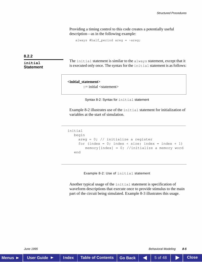
8.2.2The initial statement is similar to thealways statement, except that itis executed only once. The syntax for theinitial statement is as follows:
Syntax 8-2: Syntax for initial statement
Example 8-2 illustrates use of theinitial statement for initialization ofvariables at the start of simulation.
Example 8-2: Use of initial statement
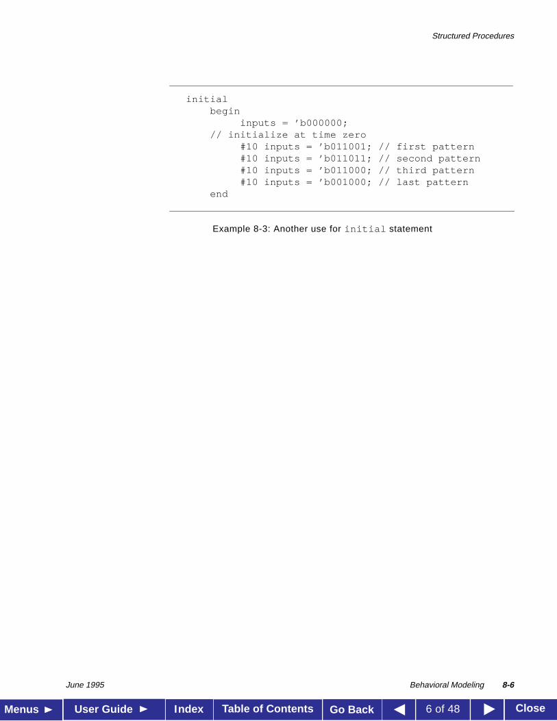
Another typical usage of theinitial statement is specification ofwaveform descriptions that execute once to provide stimulus to the mainpart of the circuit being simulated. Example 8-3 illustrates this usage.
initialStatement
<initial_statement>::= initial <statement>
initialbegin
areg = 0; // initialize a registerfor (index = 0; index < size; index = index + 1)
memory[index] = 0; //initialize a memory wordend
Structured Procedures
June 1995 Behavioral Modeling 8-6
Table of Contents CloseMenus User Guide Go BackIndex 6 of 48
Example 8-3: Another use for initial statement
initialbegin
inputs = ’b000000;// initialize at time zero
#10 inputs = ’b011001; // first pattern #10 inputs = ’b011011; // second pattern #10 inputs = ’b011000; // third pattern #10 inputs = ’b001000; // last pattern
end

Procedural Assignments
June 1995 Behavioral Modeling 8-7
Table of Contents CloseMenus User Guide Go BackIndex 7 of 48
8.3
Procedural Assignments
As described in Chapter 5,Assignments, procedural assignments are forupdatingreg , integer , time , and memory variables.
There is a significant difference between procedural assignments andcontinuous assignments, as described below:
■ Continuous assignments drive net variables and are evaluated andupdated whenever an input operand changes value.
■ Procedural assignments update the value of register variables under thecontrol of the procedural flow constructs that surround them.
The right-hand side of a procedural assignment can be any expression thatevaluates to a value. However, part-selects on the right-hand side musthave constant indices. The left-hand side indicates the variable thatreceives the assignment from the right-hand side. The left-hand side of aprocedural assignment can take one of the following forms:
■ register, integer, real, or time variable:An assignment to the name reference of one of these data types.
■ bit-select of a register, integer, real, or time variable:An assignment to a single bit that leaves the other bits untouched.
■ part-select of a register, integer, real, or time variable:A part-select of two or more contiguous bits that leaves the rest of thebits untouched. For the part-select form, onlyconstant expressions arelegal.
■ memory element:A single word of a memory. Note that bit-selects and part-selects areillegal on memory element references.
■ concatenation of any of the above:A concatenation of any of the previous four forms can be specified,which effectively partitions the result of the right-hand side expressionand assigns the partition parts, in order, to the various parts of theconcatenation.
Note: Assignment to a register differs from assignment to areal , time ,or integer variable when the right-hand side evaluates to fewer bits thanthe left-hand side.Assignment to a register does not sign-extend. Registersare unsigned; if you assign a register to an integer, real, or time variable,the variable will not sign-extend.
Procedural Assignments
June 1995 Behavioral Modeling 8-8
Table of Contents CloseMenus User Guide Go BackIndex 8 of 48
The Verilog HDL contains two types of procedural assignment statements:
■ blocking procedural assignment statements
■ non-blocking procedural assignment statements
Blocking and non-blocking procedural assignment statements specifydifferent procedural flow in sequential blocks.
8.3.1A blocking procedural assignment statement must be executed before theexecution of the statements that follow it in a sequential block (seeSection 8.8.1 on page 8-39). A blocking procedural assignment statementdoes not prevent the execution of statements that follow it in a parallelblock (see Section 8.8.2 on page 8-41).
Syntax:
The syntax for a blocking procedural assignment is as follows:
<lvalue> = <timing_control> <expression>
Wherelvalue is a data type that is valid for a procedural assignmentstatement,= is the assignment operator, andtiming_control is theoptional intra-assignment delay. Thetiming_control delay can beeither a delay control (for example,#6) or an event control (for example,@(posedge clk) ). Theexpression is the right-hand side value thesimulator assigns to the left-hand side.
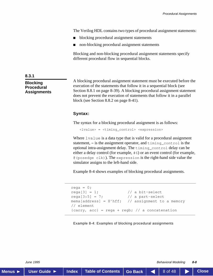
Example 8-4 shows examples of blocking procedural assignments.
Example 8-4: Examples of blocking procedural assignments
BlockingProceduralAssignments
rega = 0;rega[3] = 1; // a bit-selectrega[3:5] = 7; // a part-selectmema[address] = 8’hff; // assignment to a memory// element{carry, acc} = rega + regb; // a concatenation
Procedural Assignments
June 1995 Behavioral Modeling 8-9
Table of Contents CloseMenus User Guide Go BackIndex 9 of 48
8.3.2The non-blocking procedural assignment allows you to scheduleassignments without blocking the procedural flow. You can use thenon-blocking procedural statement whenever you want to make severalregister assignments within the same time step without regard to order ordependance upon each other.
Syntax:
The syntax for a non-blocking procedural assignment is as follows:
<lvalue> <= <timing_control> <expression>
Wherelvalue is a data type that is valid for a procedural assignmentstatement, <= is the non-blocking assignment operator, andtiming_control is the optional intra-assignment timing control. Thetiming_control delay can be either a delay control (for example,#6)or an event control (for example,@(posedge clk) ). Theexpressionis the right-hand side value the simulator assigns to the left-hand side.
The non-blocking assignment operator is the same operator the simulatoruses for the less-than-or-equal relational operator. The simulator interpretsthe<= operator to be a relational operator when you use it in an expression,and interprets the<= operator to be an assignment operator when you useit in a non-blocking procedural assignment construct.
How the simulator evaluates non-blocking proceduralassignments
When the simulator encounters a non-blocking procedural assignment, thesimulator evaluates and executes the non-blocking procedural assignmentin two steps as follows:
1. The simulator evaluates the right-hand side and schedules theassignment of the new value to take place at a time specified by aprocedural timing control.
2. At the end of the time step, in which the given delay has expired or theappropriate event has taken place, the simulator executes theassignment by assigning the value to the left-hand side.
These two steps are shown in Example 8-5.
The Non-BlockingProceduralAssignment
Procedural Assignments
June 1995 Behavioral Modeling 8-10
Table of Contents CloseMenus User Guide Go BackIndex 10 of 48
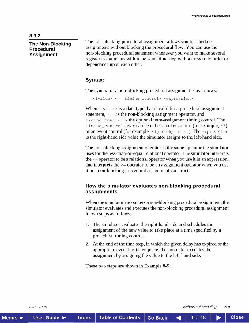
Example 8-5: How the simulator evaluates non-blocking procedural assignments
At the end of the time step means that the non-blocking assignments are thelast assignments executed in a time step—with one exception.Non-blocking assignment events can create blocking assignment events.The simulator processes these blocking assignment events after thescheduled non-blocking events.
Unlike a regular event or delay control, the non-blocking assignment doesnot block the procedural flow. The non-blocking assignment evaluates andschedules the assignment, but does not block the execution of subsequentstatements in a begin-end block, as shown in Example 8-6.
module evaluates2(out);
output out;reg a, b, c;
initialbegina = 0;b = 1;c = 0;end
always c = #5 ~c;
always @(posedge c)begina <= b;b <= a;end
endmodule
The simulatorevaluates theright-hand side of thenon-blockingassignments andschedules theassignments of thenew values atposedge c.
Step 1:
a = 0
b = 1
Step 2:
At posedge c , thesimulator updates theleft-hand side of eachnon-blockingassignment statement.
non-blockingassignmentscheduledchanges at
time 5
a = 1
b = 0
assignmentvalues are:
evaluates, schedules, andexecutes in two steps
Procedural Assignments
June 1995 Behavioral Modeling 8-11
Table of Contents CloseMenus User Guide Go BackIndex 11 of 48
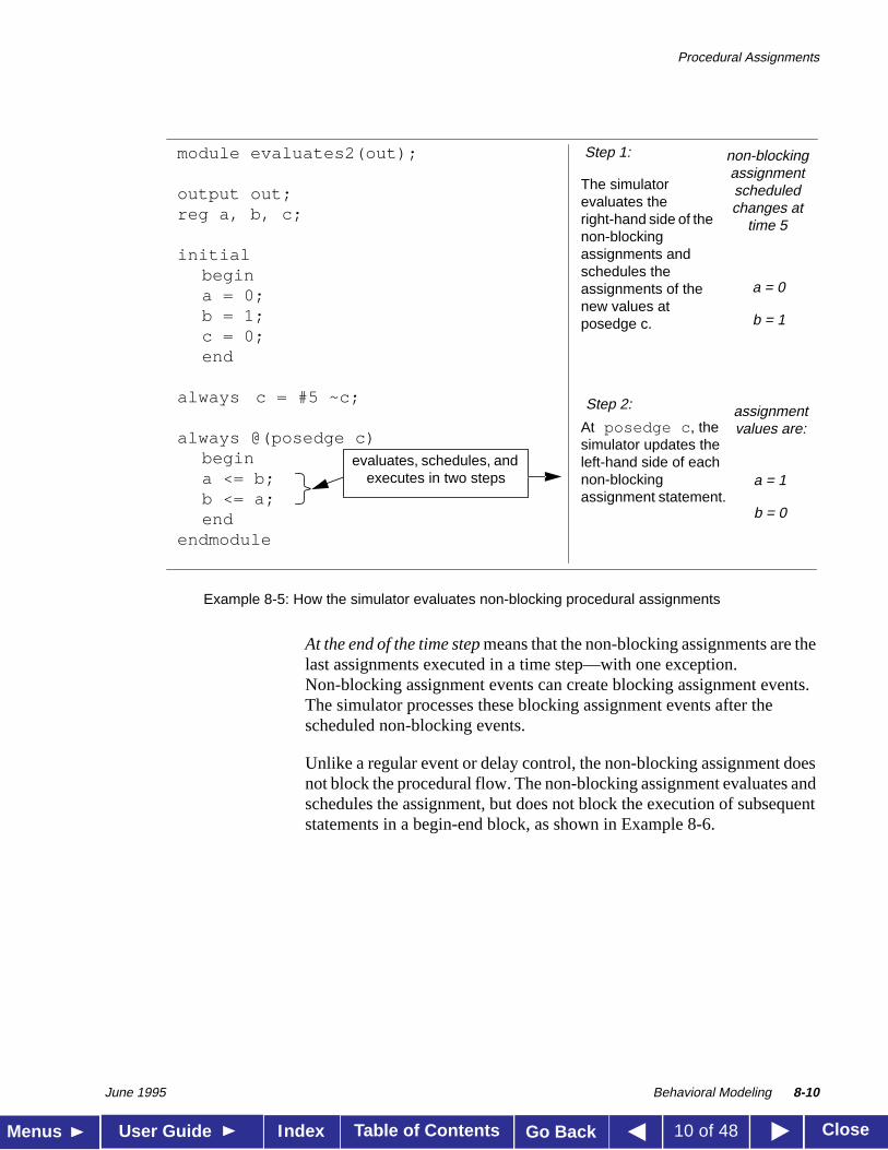
Example 8-6: Non-blocking assignments do not block execution of sequential statements
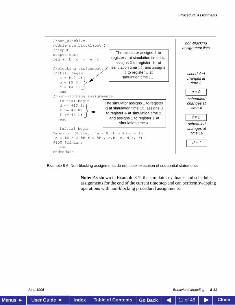
Note: As shown in Example 8-7, the simulator evaluates and schedulesassignments for the end of the current time step and can perform swappingoperations with non-blocking procedural assignments.
//non_block1.vmodule non_block1(out,);//inputoutput out;reg a, b, c, d, e, f;
//blocking assignmentsinitial begin
a = #10 1;b = #2 0;c = #4 1;end
//non-blocking assignmentsinitial begind <= #10 1;e <= #2 0;f <= #4 1;end
initial begin$monitor ($time, ,"a = %b b = %b c = %b d = %b e = %b f = %b", a,b, c, d,e, f);#100 $finish;
endendmodule
The simulator assigns 1 toregister a at simulation time 10 ,
assigns 0 to register b atsimulation time 12 , and assigns
1 to register c atsimulation time 16 .
scheduledchanges at
time 2
e = 0
f = 1
d = 1
non-blockingassignment lists
scheduledchanges at
time 4
scheduledchanges at
time 10
The simulator assigns 1 to registerd at simulation time 10 , assigns 0to register e at simulation time 2,
and assigns 1 to register f atsimulation time 4.
Procedural Assignments
June 1995 Behavioral Modeling 8-12
Table of Contents CloseMenus User Guide Go BackIndex 12 of 48
Example 8-7: Non-blocking procedural assignments used for swapping operations
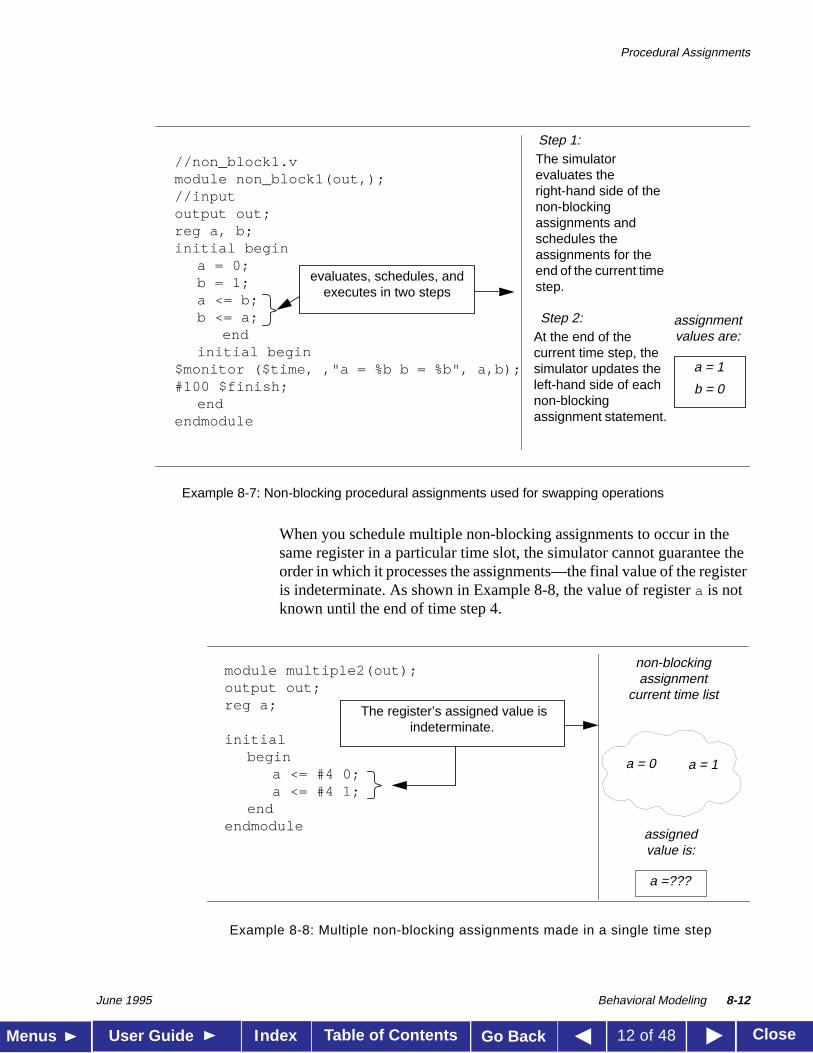
When you schedule multiple non-blocking assignments to occur in thesame register in a particular time slot, the simulator cannot guarantee theorder in which it processes the assignments—the final value of the registeris indeterminate. As shown in Example 8-8, the value of registera is notknown until the end of time step 4.
Example 8-8: Multiple non-blocking assignments made in a single time step
//non_block1.vmodule non_block1(out,);//inputoutput out;reg a, b;initial begin
a = 0;b = 1;a <= b;b <= a;
endinitial begin
$monitor ($time, ,"a = %b b = %b", a,b);#100 $finish;
endendmodule
The simulatorevaluates theright-hand side of thenon-blockingassignments andschedules theassignments for theend of the current timestep.
Step 1:
Step 2:At the end of thecurrent time step, thesimulator updates theleft-hand side of eachnon-blockingassignment statement.
a = 1
b = 0
assignmentvalues are:
evaluates, schedules, andexecutes in two steps
module multiple2(out);output out;reg a;
initialbegin
a <= #4 0;a <= #4 1;
endendmodule
The register’s assigned value isindeterminate.
a = 0 a = 1
non-blockingassignment
current time list
a =???
assignedvalue is:
Procedural Assignments
June 1995 Behavioral Modeling 8-13
Table of Contents CloseMenus User Guide Go BackIndex 13 of 48
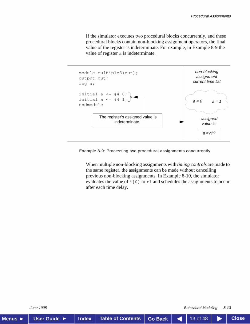
If the simulator executes two procedural blocks concurrently, and theseprocedural blocks contain non-blocking assignment operators, the finalvalue of the register is indeterminate. For example, in Example 8-9 thevalue of registera is indeterminate.
Example 8-9: Processing two procedural assignments concurrently
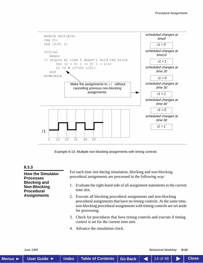
When multiple non-blocking assignments withtiming controls are made tothe same register, the assignments can be made without cancellingprevious non-blocking assignments. In Example 8-10, the simulatorevaluates the value ofi[0] to r1 and schedules the assignments to occurafter each time delay.
module multiple3(out);output out;reg a;
initial a <= #4 0;initial a <= #4 1;endmodule
a = 0 a = 1
non-blockingassignment
current time list
a =???
assignedvalue is:
The register’s assigned value isindeterminate.
Procedural Assignments
June 1995 Behavioral Modeling 8-14
Table of Contents CloseMenus User Guide Go BackIndex 14 of 48
Example 8-10: Multiple non-blocking assignments with timing controls
8.3.3For each time slot during simulation, blocking and non-blockingprocedural assignments are processed in the following way:
1. Evaluate the right-hand side of all assignment statements in the currenttime slot.
2. Execute all blocking procedural assignments and non-blockingprocedural assignments that have no timing controls. At the same time,non-blocking procedural assignments with timing controls are set asidefor processing.
3. Check for procedures that have timing controls and execute if timingcontrol is set for the current time unit.
4. Advance the simulation clock.
r1 = 0
r1 = 0
r1 = 1
r1 = 0
r1 = 1
r1 = 1
module multiple;reg r1;reg [2:0] i;
initialbegin
// starts at time 0 doesn’t hold the blockfor (i = 0; i <= 5; i = i+1)r1 <= # (i*10) i[0];
endendmodule
scheduled changes attime 50
scheduled changes attime 40
scheduled changes attime 30
scheduled changes attime 20
scheduled changes attime10
scheduled changes attime0
r1
10 20 30 40 500
Make the assignments to r1 withoutcancelling previous non-blocking
assignments.
How the SimulatorProcessesBlocking andNon-BlockingProceduralAssignments
Conditional Statement
June 1995 Behavioral Modeling 8-15
Table of Contents CloseMenus User Guide Go BackIndex 15 of 48
8.4
Conditional Statement
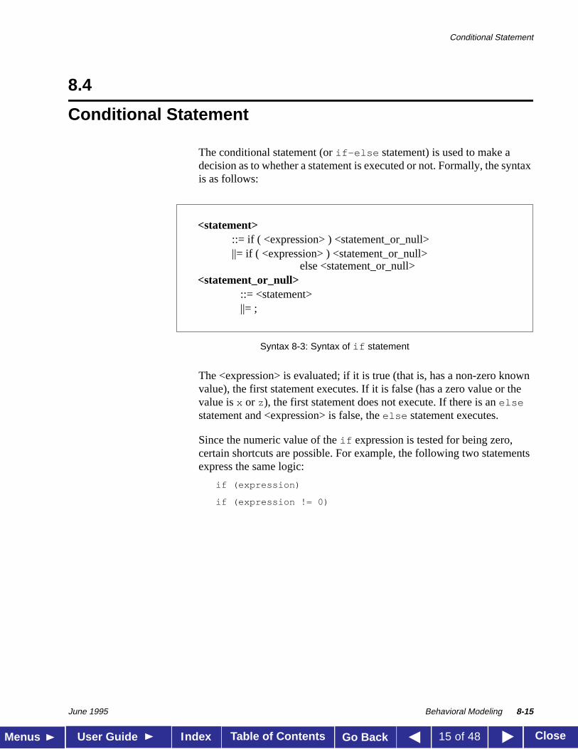
The conditional statement (orif-else statement) is used to make adecision as to whether a statement is executed or not. Formally, the syntaxis as follows:
Syntax 8-3: Syntax of if statement
The <expression> is evaluated; if it is true (that is, has a non-zero knownvalue), the first statement executes. If it is false (has a zero value or thevalue isx or z), the first statement does not execute. If there is anelsestatement and <expression> is false, theelse statement executes.
Since the numeric value of theif expression is tested for being zero,certain shortcuts are possible. For example, the following two statementsexpress the same logic:
if (expression)
if (expression != 0)
<statement>::= if ( <expression> ) <statement_or_null>||= if ( <expression> ) <statement_or_null>
else <statement_or_null><statement_or_null>
::= <statement> ||= ;
Conditional Statement
June 1995 Behavioral Modeling 8-16
Table of Contents CloseMenus User Guide Go BackIndex 16 of 48
Because theelse part of anif-else is optional, there can be confusionwhen anelse is omitted from a nestedif sequence. This is resolved byalways associating theelse with the closest previousif that lacks anelse . In Example 8-11, theelse goes with the innerif , as we haveshown by indentation.
Example 8-11: Association of else in nested if
If that association is not what you want, use a begin-end block statementto force the proper association, as shown in Example 8-12.
Example 8-12: Forcing correct association of else with if
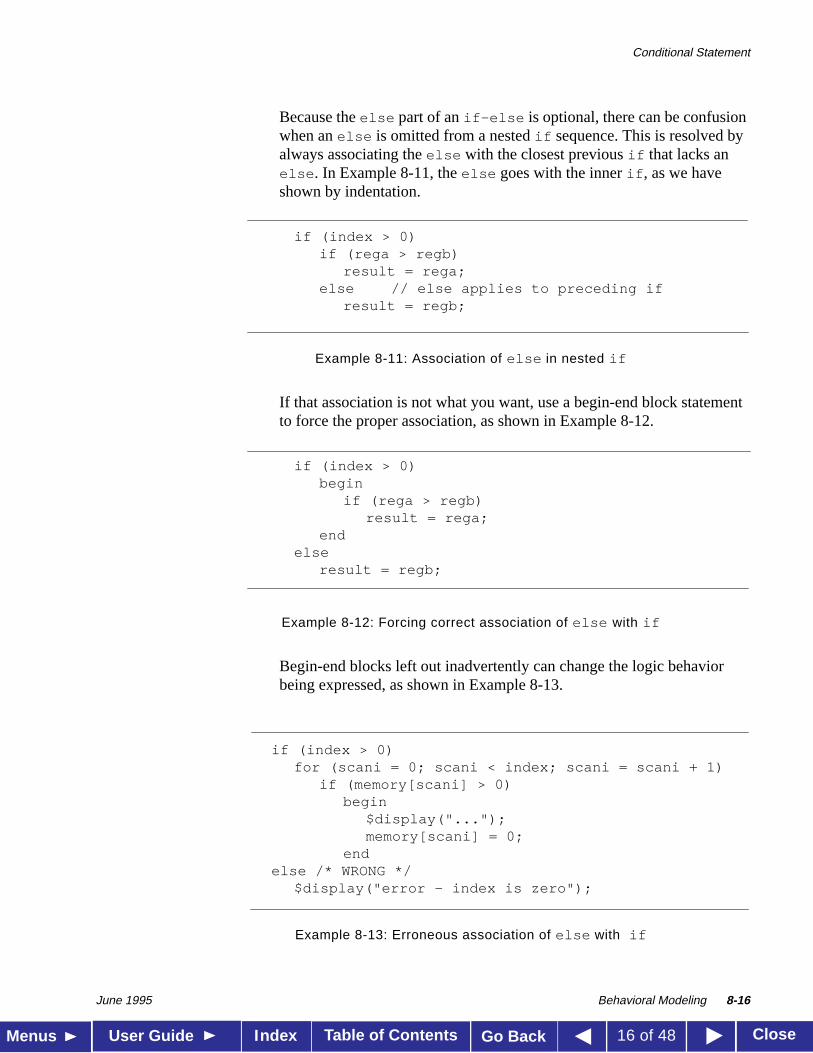
Begin-end blocks left out inadvertently can change the logic behaviorbeing expressed, as shown in Example 8-13.
Example 8-13: Erroneous association of else with if
if (index > 0)if (rega > regb)
result = rega;else // else applies to preceding if
result = regb;
if (index > 0)begin
if (rega > regb)result = rega;
endelse
result = regb;
if (index > 0)for (scani = 0; scani < index; scani = scani + 1)
if (memory[scani] > 0)begin
$display("...");memory[scani] = 0;
endelse /* WRONG */
$display("error - index is zero");
Conditional Statement
June 1995 Behavioral Modeling 8-17
Table of Contents CloseMenus User Guide Go BackIndex 17 of 48
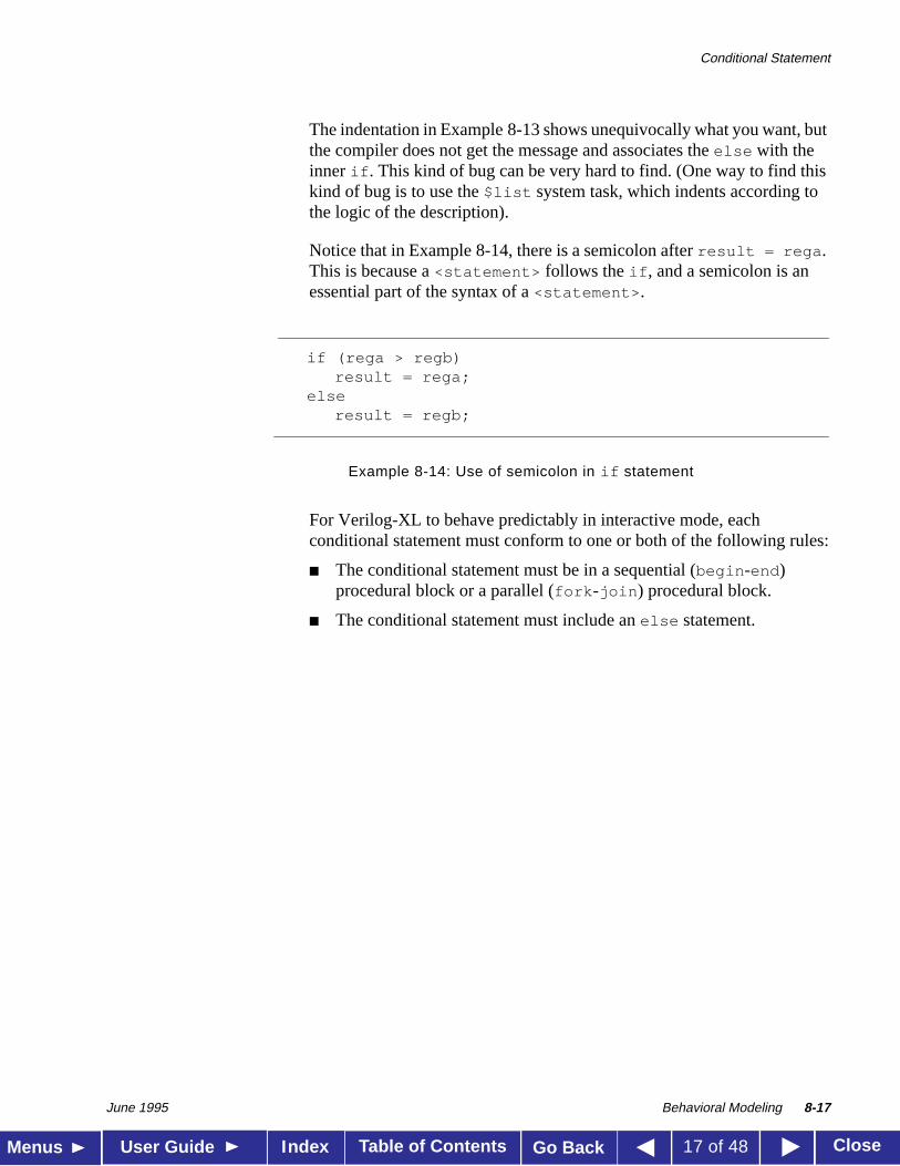
The indentation in Example 8-13 shows unequivocally what you want, butthe compiler does not get the message and associates theelse with theinner if . This kind of bug can be very hard to find. (One way to find thiskind of bug is to use the$list system task, which indents according tothe logic of the description).
Notice that in Example 8-14, there is a semicolon afterresult = rega .This is because a<statement> follows theif , and a semicolon is anessential part of the syntax of a<statement> .
Example 8-14: Use of semicolon in if statement
For Verilog-XL to behave predictably in interactive mode, eachconditional statement must conform to one or both of the following rules:
■ The conditional statement must be in a sequential (begin -end )procedural block or a parallel (fork -join ) procedural block.
■ The conditional statement must include anelse statement.
if (rega > regb)result = rega;
elseresult = regb;
Multi-Way Decision Statements
June 1995 Behavioral Modeling 8-18
Table of Contents CloseMenus User Guide Go BackIndex 18 of 48
8.5
Multi-Way Decision Statements
There are two statements that you can use to specify one or more actionsto be taken based on specified conditions:if-else-if andcase .
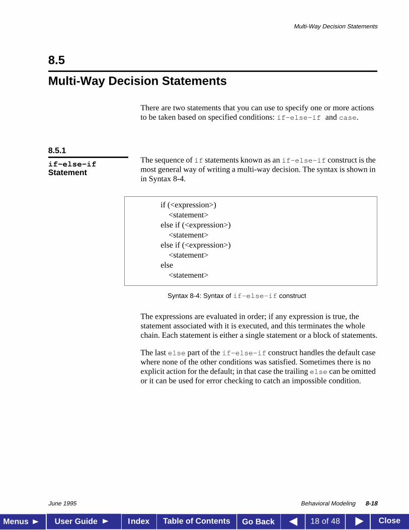
8.5.1The sequence ofif statements known as anif-else-if construct is themost general way of writing a multi-way decision. The syntax is shown inin Syntax 8-4.
Syntax 8-4: Syntax of if-else-if construct
The expressions are evaluated in order; if any expression is true, thestatement associated with it is executed, and this terminates the wholechain. Each statement is either a single statement or a block of statements.
The lastelse part of theif-else-if construct handles the default casewhere none of the other conditions was satisfied. Sometimes there is noexplicit action for the default; in that case the trailingelse can be omittedor it can be used for error checking to catch an impossible condition.
if-else-ifStatement
if (<expression>) <statement>
else if (<expression>)<statement>
else if (<expression>) <statement>
else <statement>
Multi-Way Decision Statements
June 1995 Behavioral Modeling 8-19
Table of Contents CloseMenus User Guide Go BackIndex 19 of 48
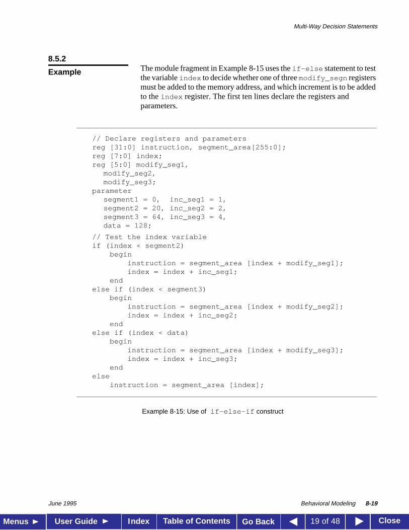
8.5.2The module fragment in Example 8-15 uses theif-else statement to testthe variableindex to decide whether one of threemodify_segn registersmust be added to the memory address, and which increment is to be addedto theindex register. The first ten lines declare the registers andparameters.
Example 8-15: Use of if-else-if construct
Example
// Declare registers and parametersreg [31:0] instruction, segment_area[255:0];reg [7:0] index;reg [5:0] modify_seg1,
modify_seg2,modify_seg3;
parametersegment1 = 0, inc_seg1 = 1,segment2 = 20, inc_seg2 = 2,segment3 = 64, inc_seg3 = 4,data = 128;
// Test the index variableif (index < segment2)
begininstruction = segment_area [index + modify_seg1];index = index + inc_seg1;
endelse if (index < segment3)
begininstruction = segment_area [index + modify_seg2];index = index + inc_seg2;
endelse if (index < data)
begininstruction = segment_area [index + modify_seg3];index = index + inc_seg3;
endelse
instruction = segment_area [index];
Multi-Way Decision Statements
June 1995 Behavioral Modeling 8-20
Table of Contents CloseMenus User Guide Go BackIndex 20 of 48
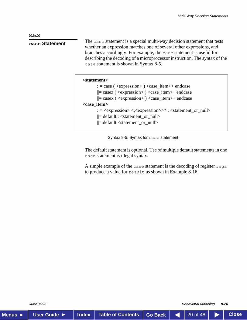
8.5.3Thecase statement is a special multi-way decision statement that testswhether an expression matches one of several other expressions, andbranches accordingly. For example, thecase statement is useful fordescribing the decoding of a microprocessor instruction. The syntax of thecase statement is shown in Syntax 8-5.
Syntax 8-5: Syntax for case statement
The default statement is optional. Use of multiple default statements in onecase statement is illegal syntax.
A simple example of thecase statement is the decoding of registerregato produce a value forresult as shown in Example 8-16.
case Statement
<statement>::= case ( <expression> ) <case_item>+ endcase||= casez ( <expression> ) <case_item>+ endcase||= casex ( <expression> ) <case_item>+ endcase
<case_item>::= <expression> <,<expression>>* : <statement_or_null>||= default : <statement_or_null>||= default <statement_or_null>
Multi-Way Decision Statements
June 1995 Behavioral Modeling 8-21
Table of Contents CloseMenus User Guide Go BackIndex 21 of 48
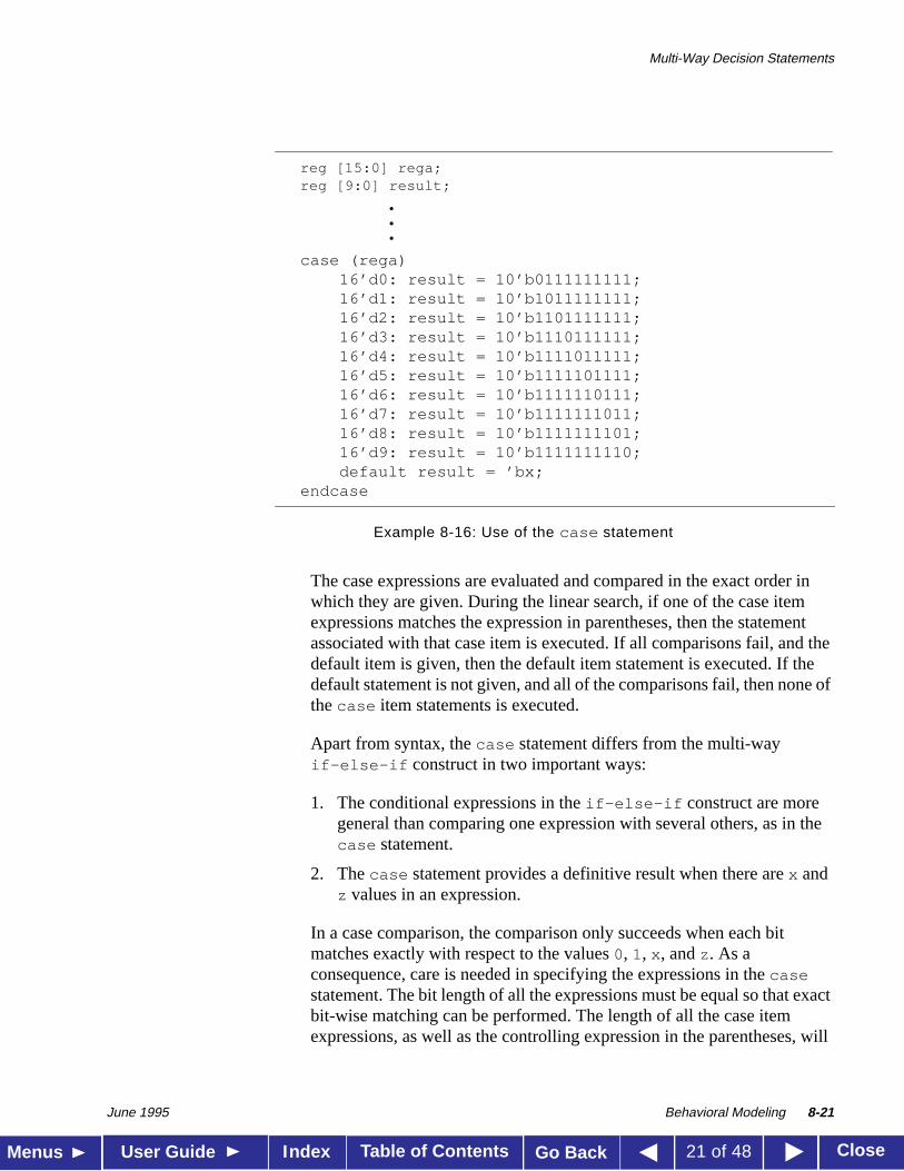
Example 8-16: Use of the case statement
The case expressions are evaluated and compared in the exact order inwhich they are given. During the linear search, if one of the case itemexpressions matches the expression in parentheses, then the statementassociated with that case item is executed. If all comparisons fail, and thedefault item is given, then the default item statement is executed. If thedefault statement is not given, and all of the comparisons fail, then none ofthecase item statements is executed.
Apart from syntax, thecase statement differs from the multi-wayif-else-if construct in two important ways:
1. The conditional expressions in theif-else-if construct are moregeneral than comparing one expression with several others, as in thecase statement.
2. Thecase statement provides a definitive result when there arex andz values in an expression.
In a case comparison, the comparison only succeeds when each bitmatches exactly with respect to the values0, 1, x , andz . As aconsequence, care is needed in specifying the expressions in thecasestatement. The bit length of all the expressions must be equal so that exactbit-wise matching can be performed. The length of all the case itemexpressions, as well as the controlling expression in the parentheses, will
reg [15:0] rega;reg [9:0] result;
•••
case (rega)16’d0: result = 10’b0111111111;16’d1: result = 10’b1011111111;16’d2: result = 10’b1101111111;16’d3: result = 10’b1110111111;16’d4: result = 10’b1111011111;16’d5: result = 10’b1111101111;16’d6: result = 10’b1111110111;16’d7: result = 10’b1111111011;16’d8: result = 10’b1111111101;16’d9: result = 10’b1111111110;default result = ’bx;
endcase
Multi-Way Decision Statements
June 1995 Behavioral Modeling 8-22
Table of Contents CloseMenus User Guide Go BackIndex 22 of 48
be made equal to the length of the longest <case_item> expression. Themost common mistake made here is to specify´bx or ´bz instead ofn’bxor n’bz , wheren is the bit length of the expression in parentheses. Thedefault length ofx andz is the word size of the host machine, usually 32bits.
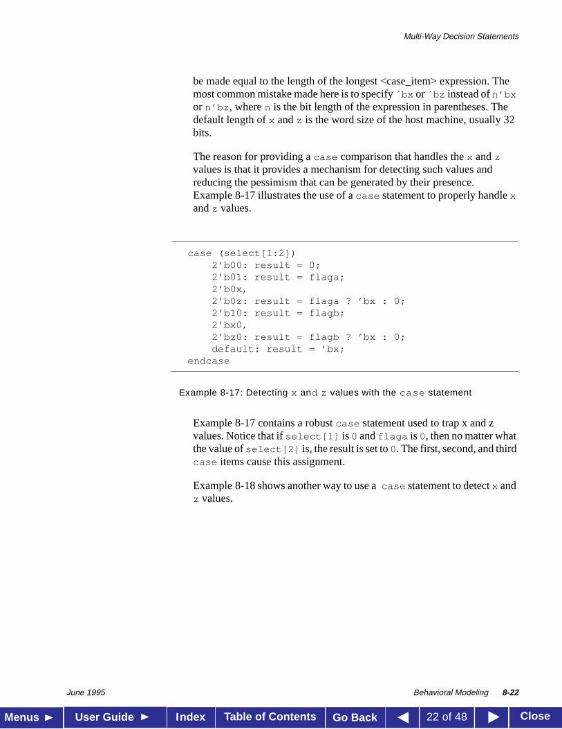
The reason for providing acase comparison that handles thex andzvalues is that it provides a mechanism for detecting such values andreducing the pessimism that can be generated by their presence.Example 8-17 illustrates the use of acase statement to properly handlexandz values.
Example 8-17: Detecting x and z values with the case statement
Example 8-17 contains a robustcase statement used to trap x and zvalues. Notice that ifselect[1] is0 andflaga is0, then no matter whatthe value ofselect[2] is, the result is set to0. The first, second, and thirdcase items cause this assignment.
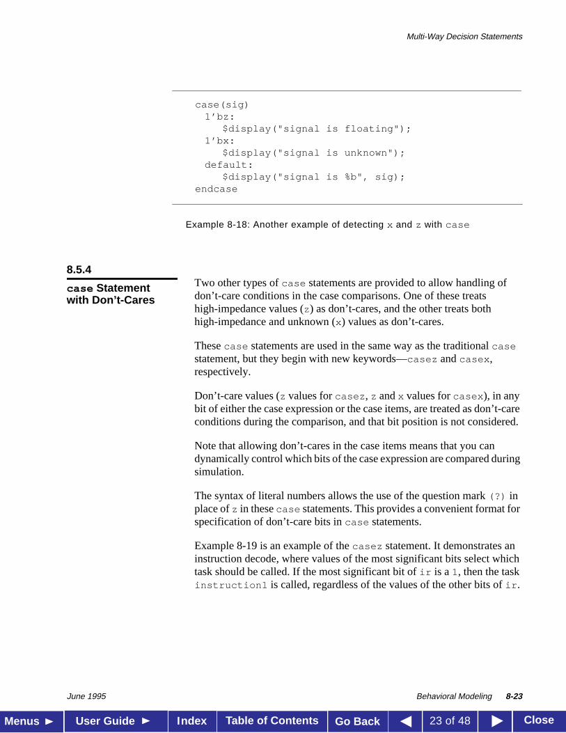
Example 8-18 shows another way to use a case statement to detectx andz values.
case (select[1:2])2’b00: result = 0;2’b01: result = flaga;2’b0x,2’b0z: result = flaga ? ’bx : 0;2’b10: result = flagb;2’bx0,2’bz0: result = flagb ? ’bx : 0;default: result = ’bx;
endcase
Multi-Way Decision Statements
June 1995 Behavioral Modeling 8-23
Table of Contents CloseMenus User Guide Go BackIndex 23 of 48
Example 8-18: Another example of detecting x and z with case
8.5.4Two other types ofcase statements are provided to allow handling ofdon’t-care conditions in the case comparisons. One of these treatshigh-impedance values (z) as don’t-cares, and the other treats bothhigh-impedance and unknown (x) values as don’t-cares.
Thesecase statements are used in the same way as the traditionalcasestatement, but they begin with new keywords—casez andcasex ,respectively.
Don’t-care values (z values forcasez , z andx values forcasex ), in anybit of either the case expression or the case items, are treated as don’t-careconditions during the comparison, and that bit position is not considered.
Note that allowing don’t-cares in the case items means that you candynamically control which bits of the case expression are compared duringsimulation.
The syntax of literal numbers allows the use of the question mark(?) inplace ofz in thesecase statements. This provides a convenient format forspecification of don’t-care bits incase statements.
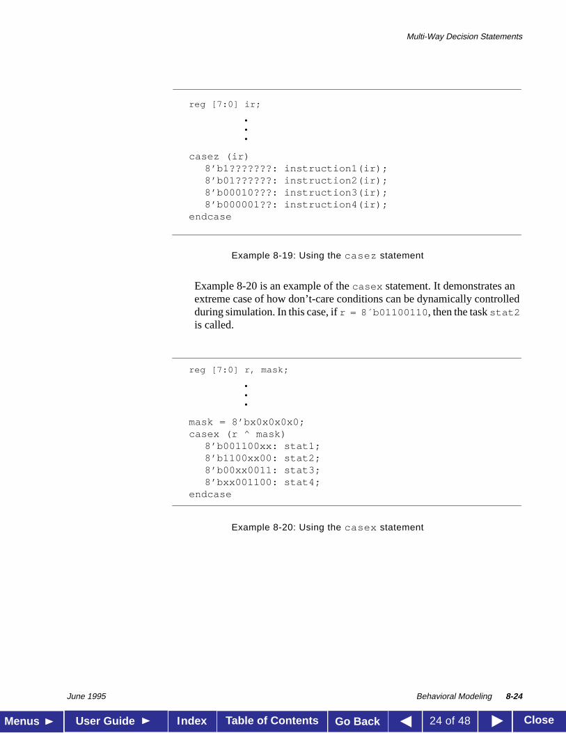
Example 8-19 is an example of thecasez statement. It demonstrates aninstruction decode, where values of the most significant bits select whichtask should be called. If the most significant bit ofir is a1, then the taskinstruction1 is called, regardless of the values of the other bits ofir .
case(sig)1’bz:
$display("signal is floating");1’bx:
$display("signal is unknown");default:
$display("signal is %b", sig); endcase
case Statementwith Don’t-Cares
Multi-Way Decision Statements
June 1995 Behavioral Modeling 8-24
Table of Contents CloseMenus User Guide Go BackIndex 24 of 48
Example 8-19: Using the casez statement
Example 8-20 is an example of thecasex statement. It demonstrates anextreme case of how don’t-care conditions can be dynamically controlledduring simulation. In this case, ifr = 8´b01100110 , then the taskstat2is called.
Example 8-20: Using the casex statement
reg [7:0] ir;
•••
casez (ir)8’b1???????: instruction1(ir);8’b01??????: instruction2(ir);8’b00010???: instruction3(ir);8’b000001??: instruction4(ir);
endcase
reg [7:0] r, mask;
•••
mask = 8’bx0x0x0x0;casex (r ^ mask)
8’b001100xx: stat1;8’b1100xx00: stat2;8’b00xx0011: stat3;8’bxx001100: stat4;
endcase
Looping Statements
June 1995 Behavioral Modeling 8-25
Table of Contents CloseMenus User Guide Go BackIndex 25 of 48
8.6
Looping Statements
There are four types of looping statements. They provide a means ofcontrolling the execution of a statement zero, one, or more times.
■ forever continuously executes a statement.
■ repeat executes a statement a fixed number of times.
■ while executes a statement until an expression becomes false. If theexpression starts out false, the statement is not executed at all.
■ for controls execution of its associated statement(s) by a three-stepprocess, as follows:
1. executes an assignment normally used to initialize a variable thatcontrols the number of loops executed
2. evaluates an expression—if the result is zero, thefor loop exits,and if it is not zero, thefor loop executes its associatedstatement(s) and then performs step 3
3. executes an assignment normally used to modify the value of theloop-control variable, then repeats step 2
Looping Statements
June 1995 Behavioral Modeling 8-26
Table of Contents CloseMenus User Guide Go BackIndex 26 of 48
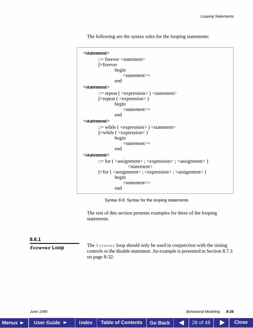
The following are the syntax rules for the looping statements:
Syntax 8-6: Syntax for the looping statements
The rest of this section presents examples for three of the loopingstatements.
8.6.1The forever loop should only be used in conjunction with the timingcontrols or the disable statement. An example is presented in Section 8.7.3on page 8-32.
<statement>::= forever <statement>||=forever
begin<statement>+
end<statement>
::= repeat ( <expression> ) <statement>||=repeat ( <expression> )
begin<statement>+
end<statement>
::= while ( <expression> ) <statement>||=while ( <expression> )
begin<statement>+
end<statement>
::= for ( <assignment> ; <expression> ; <assignment> )<statement>
||=for ( <assignment> ; <expression> ; <assignment> )begin
<statement>+end
forever Loop
Looping Statements
June 1995 Behavioral Modeling 8-27
Table of Contents CloseMenus User Guide Go BackIndex 27 of 48
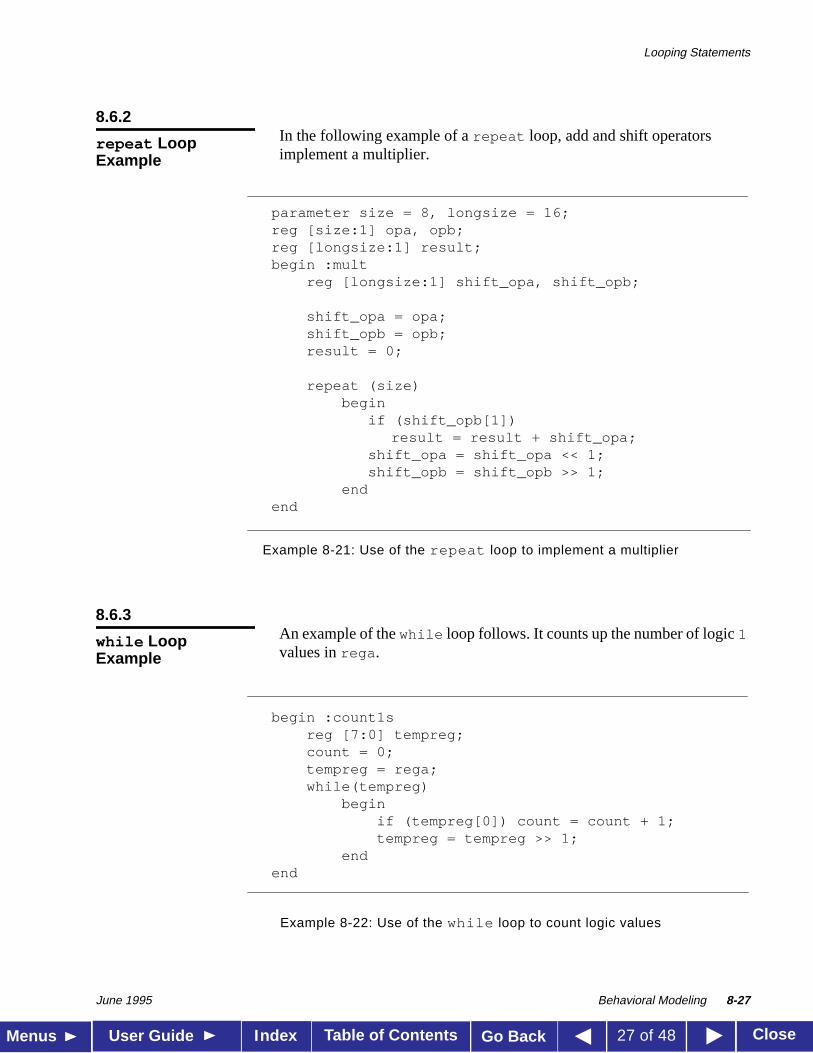
8.6.2In the following example of arepeat loop, add and shift operatorsimplement a multiplier.
Example 8-21: Use of the repeat loop to implement a multiplier
8.6.3An example of thewhile loop follows. It counts up the number of logic1values inrega .
Example 8-22: Use of the while loop to count logic values
repeat LoopExample
parameter size = 8, longsize = 16;reg [size:1] opa, opb;reg [longsize:1] result;begin :mult
reg [longsize:1] shift_opa, shift_opb;
shift_opa = opa;shift_opb = opb;result = 0;
repeat (size)begin
if (shift_opb[1])result = result + shift_opa;
shift_opa = shift_opa << 1;shift_opb = shift_opb >> 1;
endend
while LoopExample
begin :count1sreg [7:0] tempreg;count = 0;tempreg = rega;while(tempreg)
beginif (tempreg[0]) count = count + 1;tempreg = tempreg >> 1;
endend
Looping Statements
June 1995 Behavioral Modeling 8-28
Table of Contents CloseMenus User Guide Go BackIndex 28 of 48
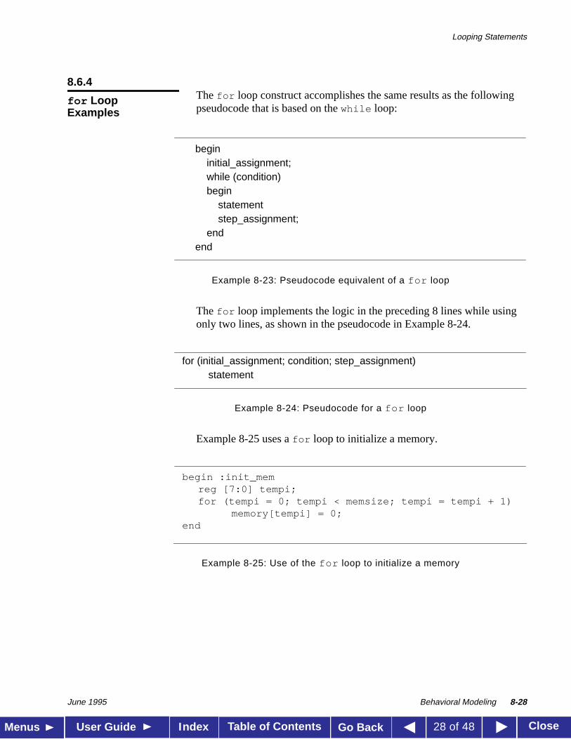
8.6.4The for loop construct accomplishes the same results as the followingpseudocode that is based on thewhile loop:
Example 8-23: Pseudocode equivalent of a for loop
The for loop implements the logic in the preceding 8 lines while usingonly two lines, as shown in the pseudocode in Example 8-24.
Example 8-24: Pseudocode for a for loop
Example 8-25 uses afor loop to initialize a memory.
Example 8-25: Use of the for loop to initialize a memory
for LoopExamples
begininitial_assignment;while (condition)begin
statementstep_assignment;
endend
for (initial_assignment; condition; step_assignment)statement
begin :init_memreg [7:0] tempi;for (tempi = 0; tempi < memsize; tempi = tempi + 1)
memory[tempi] = 0;end
Looping Statements
June 1995 Behavioral Modeling 8-29
Table of Contents CloseMenus User Guide Go BackIndex 29 of 48
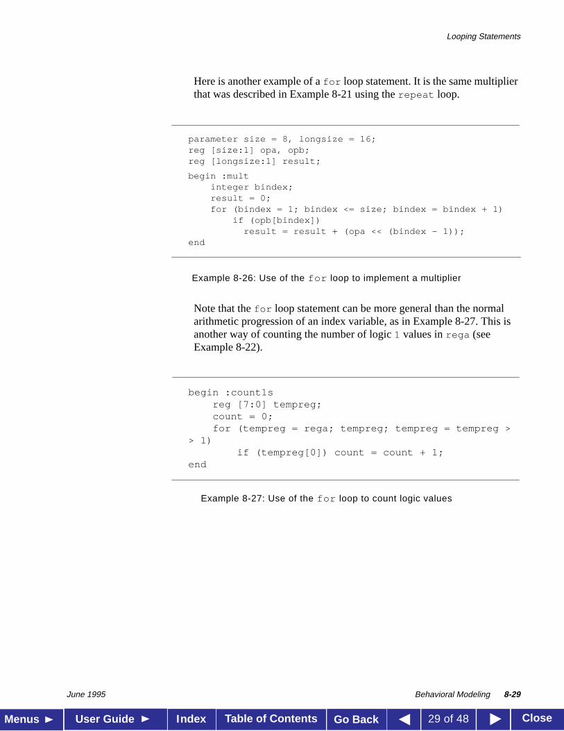
Here is another example of afor loop statement. It is the same multiplierthat was described in Example 8-21 using therepeat loop.
Example 8-26: Use of the for loop to implement a multiplier
Note that thefor loop statement can be more general than the normalarithmetic progression of an index variable, as in Example 8-27. This isanother way of counting the number of logic1 values inrega (seeExample 8-22).
Example 8-27: Use of the for loop to count logic values
parameter size = 8, longsize = 16;reg [size:1] opa, opb;reg [longsize:1] result;
begin :multinteger bindex;result = 0;for (bindex = 1; bindex <= size; bindex = bindex + 1)
if (opb[bindex])result = result + (opa << (bindex - 1));
end
begin :count1sreg [7:0] tempreg;count = 0;for (tempreg = rega; tempreg; tempreg = tempreg >
> 1)if (tempreg[0]) count = count + 1;
end
Procedural Timing Controls
June 1995 Behavioral Modeling 8-30
Table of Contents CloseMenus User Guide Go BackIndex 30 of 48
8.7
Procedural Timing Controls
The Verilog language provides two types of explicit timing control overwhen in simulation time procedural statements are to occur. The first typeis a delay control in which an expression specifies the time durationbetween initially encountering the statement and when the statementactually executes. The delay expression can be a dynamic function of thestate of the circuit, but is usually a simple number that separates statementexecutions in time. The delay control is an important feature whenspecifying stimulus waveform descriptions. It is described in Sections8.7.1, 8.7.2, and 8.7.7.
The second type of timing control is the event expression, which allowsstatement execution to wait for the occurrence of some simulation eventoccurring in a procedure executing concurrently with this procedure. Asimulation event can be a change of value on a net or register (an implicitevent), or the occurrence of an explicitly named event that is triggeredfrom other procedures (an explicit event). Most often, an event control is apositive or negative edge on a clock signal. Sections 8.7.3 through 8.7.7discuss event control.
In Verilog, actions are scheduled in the future through the use of delaycontrols. A general principle of the Verilog language is that “where you donot see a timing control, simulation time does not advance”—if youspecify no timing delays, the simulation completes at time zero. Toschedule activity for the future, use one of the following methods of timingcontrol:
■ a delay control, which is introduced by the number symbol (#)
■ anevent control, which is introduced by the at symbol (@)
■ the wait statement, which operates like a combination of the eventcontrol and thewhile loop
The next sections discuss these three methods.
Procedural Timing Controls
June 1995 Behavioral Modeling 8-31
Table of Contents CloseMenus User Guide Go BackIndex 31 of 48
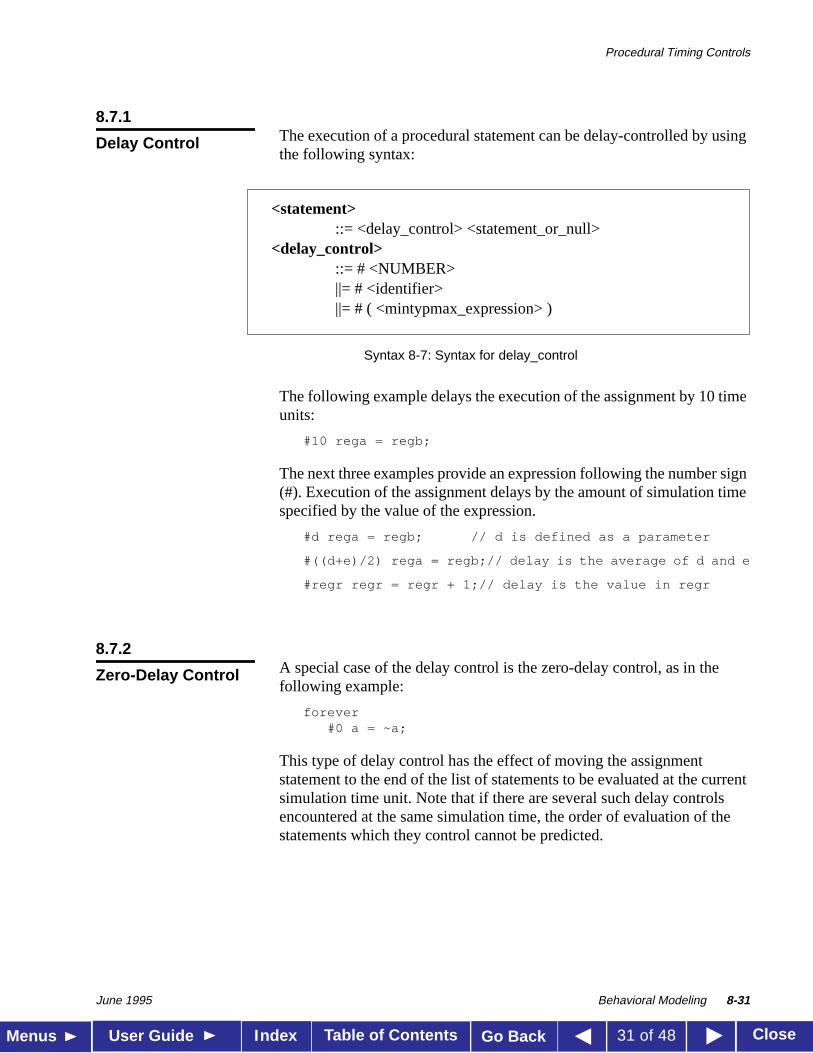
8.7.1The execution of a procedural statement can be delay-controlled by usingthe following syntax:
Syntax 8-7: Syntax for delay_control
The following example delays the execution of the assignment by 10 timeunits:
#10 rega = regb;
The next three examples provide an expression following the number sign(#). Execution of the assignment delays by the amount of simulation timespecified by the value of the expression.
#d rega = regb; // d is defined as a parameter
#((d+e)/2) rega = regb;// delay is the average of d and e
#regr regr = regr + 1;// delay is the value in regr
8.7.2A special case of the delay control is the zero-delay control, as in thefollowing example:
forever#0 a = ~a;
This type of delay control has the effect of moving the assignmentstatement to the end of the list of statements to be evaluated at the currentsimulation time unit. Note that if there are several such delay controlsencountered at the same simulation time, the order of evaluation of thestatements which they control cannot be predicted.
Delay Control
<statement> ::= <delay_control> <statement_or_null>
<delay_control> ::= # <NUMBER> ||= # <identifier> ||= # ( <mintypmax_expression> )
Zero-Delay Control
Procedural Timing Controls
June 1995 Behavioral Modeling 8-32
Table of Contents CloseMenus User Guide Go BackIndex 32 of 48
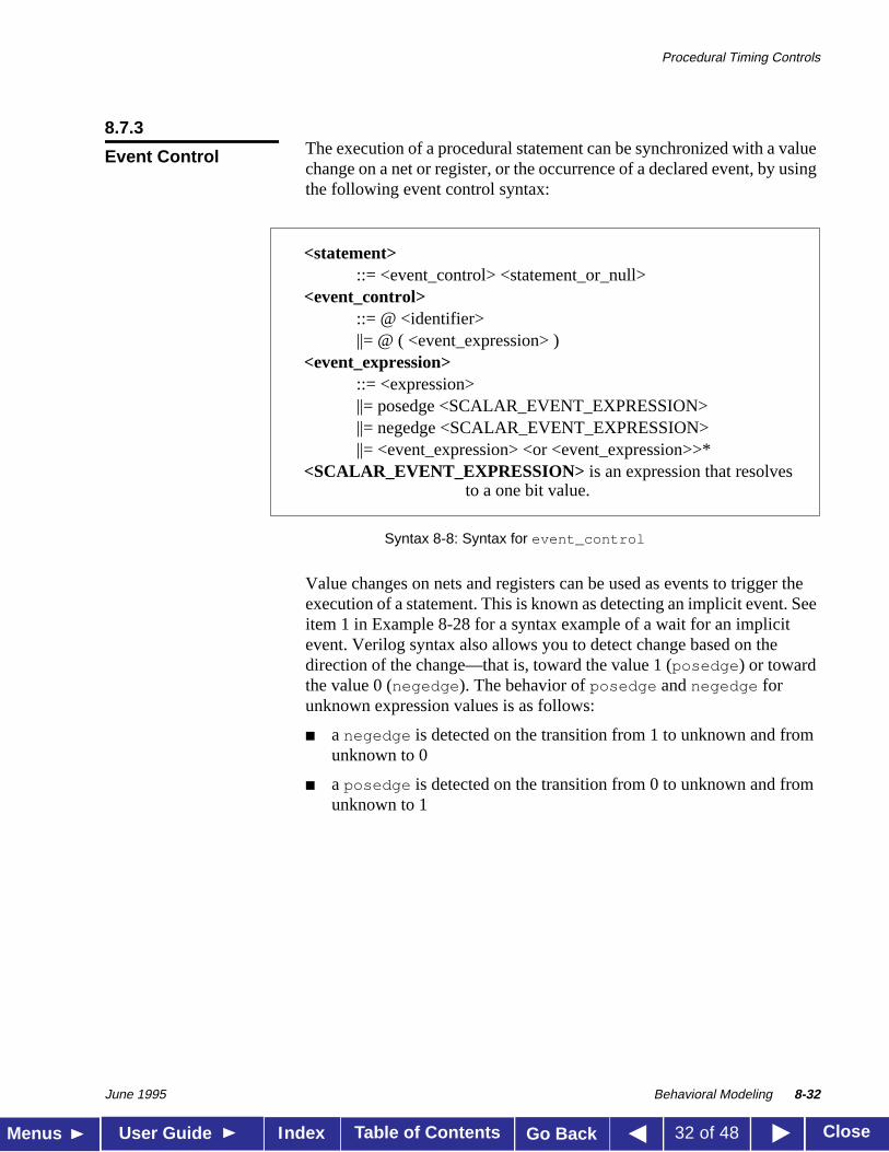
8.7.3The execution of a procedural statement can be synchronized with a valuechange on a net or register, or the occurrence of a declared event, by usingthe following event control syntax:
Syntax 8-8: Syntax for event_control
Value changes on nets and registers can be used as events to trigger theexecution of a statement. This is known as detecting an implicit event. Seeitem 1 in Example 8-28 for a syntax example of a wait for an implicitevent. Verilog syntax also allows you to detect change based on thedirection of the change—that is, toward the value 1 (posedge ) or towardthe value 0 (negedge ). The behavior ofposedge andnegedge forunknown expression values is as follows:
■ a negedge is detected on the transition from 1 to unknown and fromunknown to 0
■ a posedge is detected on the transition from 0 to unknown and fromunknown to 1
Event Control
<statement>::= <event_control> <statement_or_null>
<event_control>::= @ <identifier>||= @ ( <event_expression> )
<event_expression>::= <expression>||= posedge <SCALAR_EVENT_EXPRESSION>||= negedge <SCALAR_EVENT_EXPRESSION>||= <event_expression> <or <event_expression>>*
<SCALAR_EVENT_EXPRESSION> is an expression that resolves to a one bit value.
Procedural Timing Controls
June 1995 Behavioral Modeling 8-33
Table of Contents CloseMenus User Guide Go BackIndex 33 of 48
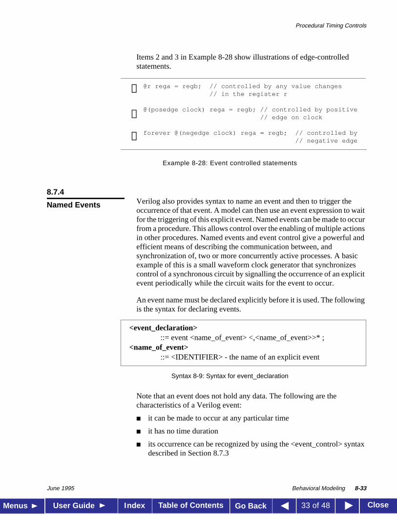
Items 2 and 3 in Example 8-28 show illustrations of edge-controlledstatements.
Example 8-28: Event controlled statements
8.7.4Verilog also provides syntax to name an event and then to trigger theoccurrence of that event. A model can then use an event expression to waitfor the triggering of this explicit event. Named events can be made to occurfrom a procedure. This allows control over the enabling of multiple actionsin other procedures. Named events and event control give a powerful andefficient means of describing the communication between, andsynchronization of, two or more concurrently active processes. A basicexample of this is a small waveform clock generator that synchronizescontrol of a synchronous circuit by signalling the occurrence of an explicitevent periodically while the circuit waits for the event to occur.
An event name must be declared explicitly before it is used. The followingis the syntax for declaring events.
Syntax 8-9: Syntax for event_declaration
Note that an event does not hold any data. The following are thecharacteristics of a Verilog event:
■ it can be made to occur at any particular time
■ it has no time duration
■ its occurrence can be recognized by using the <event_control> syntaxdescribed in Section 8.7.3
@r rega = regb; // controlled by any value changes // in the register r
@(posedge clock) rega = regb; // controlled by positive // edge on clock
forever @(negedge clock) rega = regb; // controlled by// negative edge
➊
➋
➌
Named Events
<event_declaration> ::= event <name_of_event> <,<name_of_event>>* ;
<name_of_event> ::= <IDENTIFIER> - the name of an explicit event
Procedural Timing Controls
June 1995 Behavioral Modeling 8-34
Table of Contents CloseMenus User Guide Go BackIndex 34 of 48
The power of the explicit event is that it can represent any generalhappening. For example, it can represent a positive edge of a clock signal,or it can represent a microprocessor transferring data down a serialcommunications channel. A declared event is made to occur by theactivation of an event-triggering statement of the following syntax:
-> <name_of_event> ;
An event-controlled statement (for example,@trig rega = regb; )causes simulation of its containing procedure to wait until some otherprocedure executes the appropriate event-triggering statement (forexample,->trig; ).
8.7.5The ORing of any number of events can be expressed such that theoccurrence of any one will trigger the execution of the statement. The nexttwo examples show the ORing of two and three events respectively.
@(trig or enable) rega = regb;// controlled by trig or enable
@(posedge clock_a or posedge clock_b or trig) rega = regb;
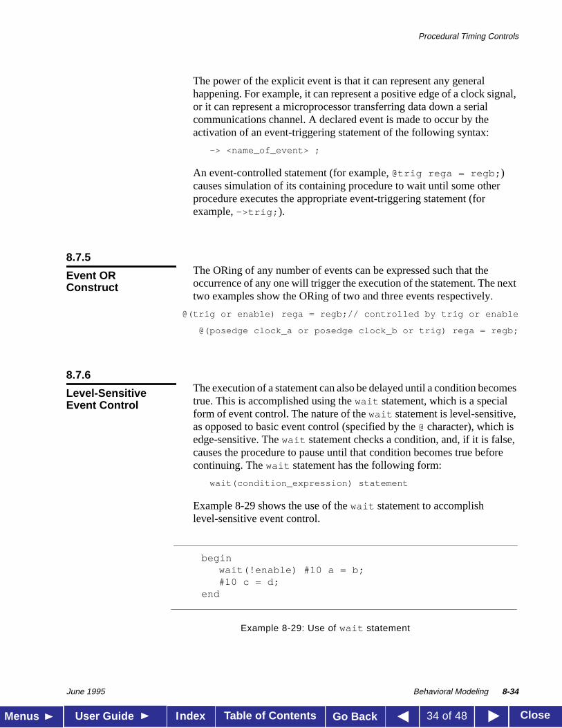
8.7.6The execution of a statement can also be delayed until a condition becomestrue. This is accomplished using thewait statement, which is a specialform of event control. The nature of thewait statement is level-sensitive,as opposed to basic event control (specified by the@ character), which isedge-sensitive. Thewait statement checks a condition, and, if it is false,causes the procedure to pause until that condition becomes true beforecontinuing. Thewait statement has the following form:
wait(condition_expression) statement
Example 8-29 shows the use of thewait statement to accomplishlevel-sensitive event control.
Example 8-29: Use of wait statement
Event ORConstruct
Level-SensitiveEvent Control
beginwait(!enable) #10 a = b;#10 c = d;
end
Procedural Timing Controls
June 1995 Behavioral Modeling 8-35
Table of Contents CloseMenus User Guide Go BackIndex 35 of 48
If the value ofenable is one when the block is entered, thewaitstatement delays the evaluation of the next statement (#10 a = b; ) untilthe value ofenable changes to zero. Ifenable is already zero when thebegin-end block is entered, then the next statement is evaluatedimmediately and no delay occurs.
8.7.7The delay and event control constructs previously described precede astatement and delay its execution. The intra-assignment delay and eventcontrols are contained within an assignment statement and modify the flowof activity in a slightly different way.
Encountering an intra-assignment delay or event control delays theassignment just as a regular delay or event control does, but the right-handside expression is evaluated before the delay, instead of after the delay.This allows data swap and data shift operations to be described without theneed for temporary variables. This section describes the purpose ofintra-assignment timing controls and therepeat timing control that canbe used in intra-assignment delays.
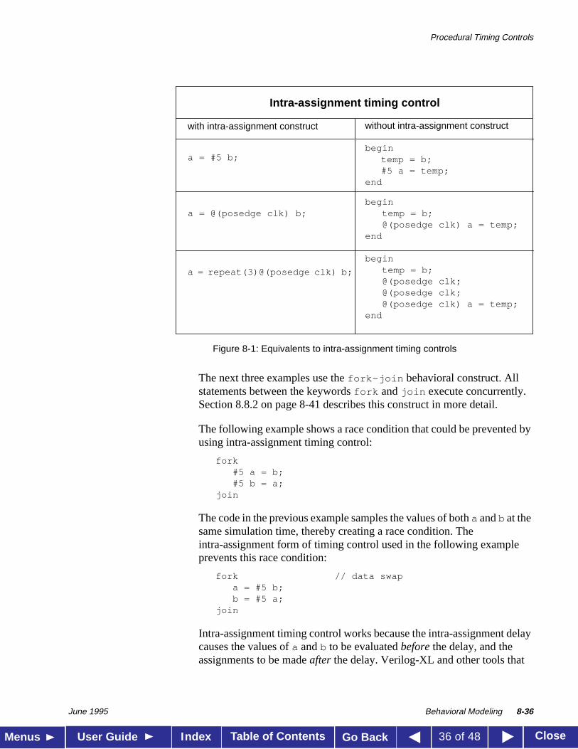
Figure 8-1 illustrates the philosophy of intra-assignment timing controlsby showing the code that could accomplish the same timing effect withoutusing intra-assignment.
Intra-AssignmentTiming Controls
Procedural Timing Controls
June 1995 Behavioral Modeling 8-36
Table of Contents CloseMenus User Guide Go BackIndex 36 of 48
Figure 8-1: Equivalents to intra-assignment timing controls
The next three examples use thefork-join behavioral construct. Allstatements between the keywordsfork andjoin execute concurrently.Section 8.8.2 on page 8-41 describes this construct in more detail.
The following example shows a race condition that could be prevented byusing intra-assignment timing control:
fork#5 a = b;#5 b = a;
join
The code in the previous example samples the values of botha andb at thesame simulation time, thereby creating a race condition. Theintra-assignment form of timing control used in the following exampleprevents this race condition:
fork // data swapa = #5 b;b = #5 a;
join
Intra-assignment timing control works because the intra-assignment delaycauses the values ofa andb to be evaluatedbefore the delay, and theassignments to be madeafter the delay. Verilog-XL and other tools that
Intra-assignment timing control
a = #5 b;begin
temp = b;#5 a = temp;
end
a = @(posedge clk) b;begin
temp = b;@(posedge clk) a = temp;
end
a = repeat(3)@(posedge clk) b;
begintemp = b;@(posedge clk;@(posedge clk;@(posedge clk) a = temp;
end
with intra-assignment construct without intra-assignment construct
Procedural Timing Controls
June 1995 Behavioral Modeling 8-37
Table of Contents CloseMenus User Guide Go BackIndex 37 of 48
implement intra-assignment timing control use temporary storage inevaluating each expression on the right-hand side.
Intra-assignment waiting forevents is also effective. In the example below,the right-hand-side expressions are evaluated when the assignmentstatements are encountered, but the assignments are delayed until therising edge of the clock signal.
fork // data shifta = @(posedge clk) b;b = @(posedge clk) c;
join
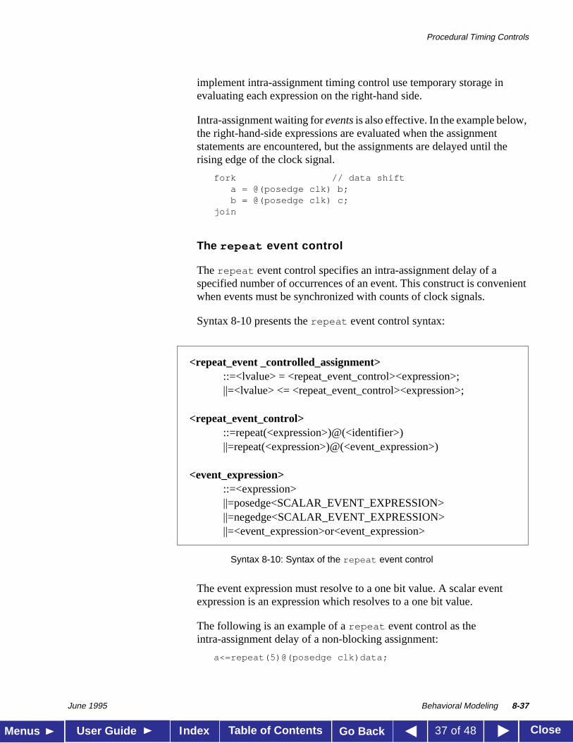
The repeat event control
Therepeat event control specifies an intra-assignment delay of aspecified number of occurrences of an event. This construct is convenientwhen events must be synchronized with counts of clock signals.
Syntax 8-10 presents therepeat event control syntax:
Syntax 8-10: Syntax of the repeat event control
The event expression must resolve to a one bit value. A scalar eventexpression is an expression which resolves to a one bit value.
The following is an example of arepeat event control as theintra-assignment delay of a non-blocking assignment:
a<=repeat(5)@(posedge clk)data;
<repeat_event _controlled_assignment>::=<lvalue> = <repeat_event_control><expression>;||=<lvalue> <= <repeat_event_control><expression>;
<repeat_event_control>::=repeat(<expression>)@(<identifier>)||=repeat(<expression>)@(<event_expression>)
<event_expression>::=<expression>||=posedge<SCALAR_EVENT_EXPRESSION>||=negedge<SCALAR_EVENT_EXPRESSION>||=<event_expression>or<event_expression>
Procedural Timing Controls
June 1995 Behavioral Modeling 8-38
Table of Contents CloseMenus User Guide Go BackIndex 38 of 48
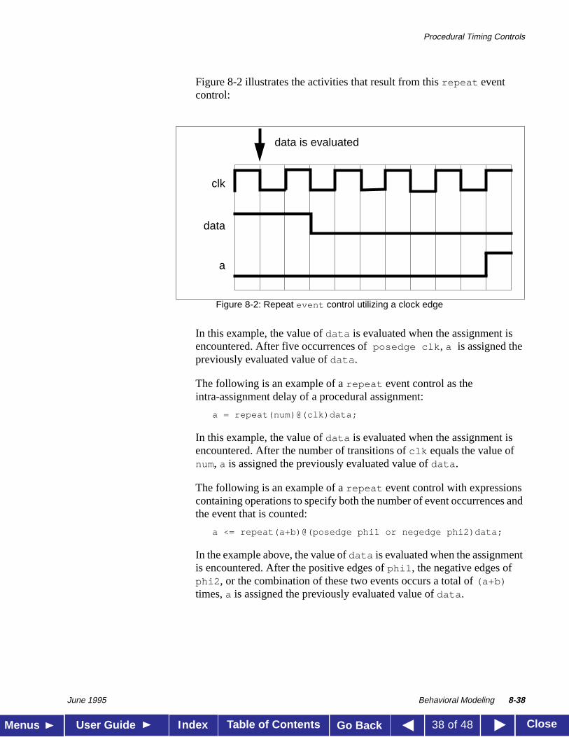
Figure 8-2 illustrates the activities that result from thisrepeat eventcontrol:
Figure 8-2: Repeat event control utilizing a clock edge
In this example, the value ofdata is evaluated when the assignment isencountered. After five occurrences of posedge clk , a is assigned thepreviously evaluated value ofdata .
The following is an example of arepeat event control as theintra-assignment delay of a procedural assignment:
a = repeat(num)@(clk)data;
In this example, the value ofdata is evaluated when the assignment isencountered. After the number of transitions ofclk equals the value ofnum, a is assigned the previously evaluated value ofdata .
The following is an example of arepeat event control with expressionscontaining operations to specify both the number of event occurrences andthe event that is counted:
a <= repeat(a+b)@(posedge phi1 or negedge phi2)data;
In the example above, the value ofdata is evaluated when the assignmentis encountered. After the positive edges ofphi1 , the negative edges ofphi2 , or the combination of these two events occurs a total of(a+b)times,a is assigned the previously evaluated value ofdata .
clk
data
a
data is evaluated
Block Statements
June 1995 Behavioral Modeling 8-39
Table of Contents CloseMenus User Guide Go BackIndex 39 of 48
8.8
Block Statements
The block statements are a means of grouping two or more statementstogether so that they act syntactically like a single statement. We havealready introduced and used the sequential block statement which isdelimited by the keywordsbegin andend . Section 8.8.1 discussessequential blocks in more detail.
A second type of block, delimited by the keywordsfork andjoin , is usedfor executing statements in parallel. Afork-join block is known as aparallel block, and enables procedures to execute concurrently throughtime. Section 8.8.2 discusses parallel blocks.
8.8.1A sequential block has the following characteristics:
■ Statements execute in sequence, one after another.
■ The delays are cumulative; each statement executes after all the delayspreceding it have elapsed.
■ Control passes out of the block after the last statement executes.
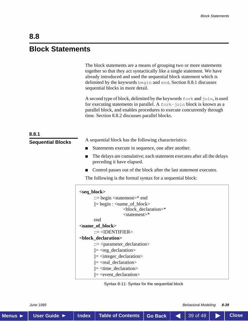
The following is the formal syntax for a sequential block:
Syntax 8-11: Syntax for the sequential block
Sequential Blocks
<seq_block>::= begin <statement>* end||= begin : <name_of_block>
<block_declaration>*<statement>*
end<name_of_block>
::= <IDENTIFIER><block_declaration>
::= <parameter_declaration>||= <reg_declaration>||= <integer_declaration>||= <real_declaration>||= <time_declaration>||= <event_declaration>
Block Statements
June 1995 Behavioral Modeling 8-40
Table of Contents CloseMenus User Guide Go BackIndex 40 of 48
A sequential block enables the following two assignments to have adeterministic result:
beginareg = breg;creg = areg; // creg becomes the value of breg
end
Here the first assignment is performed andareg is updated before controlpasses to the second assignment.
Delay control can be used in a sequential block to separate the twoassignments in time.
beginareg = breg;#10 creg = areg; // this gives a delay of 10 time
end // units between assignments
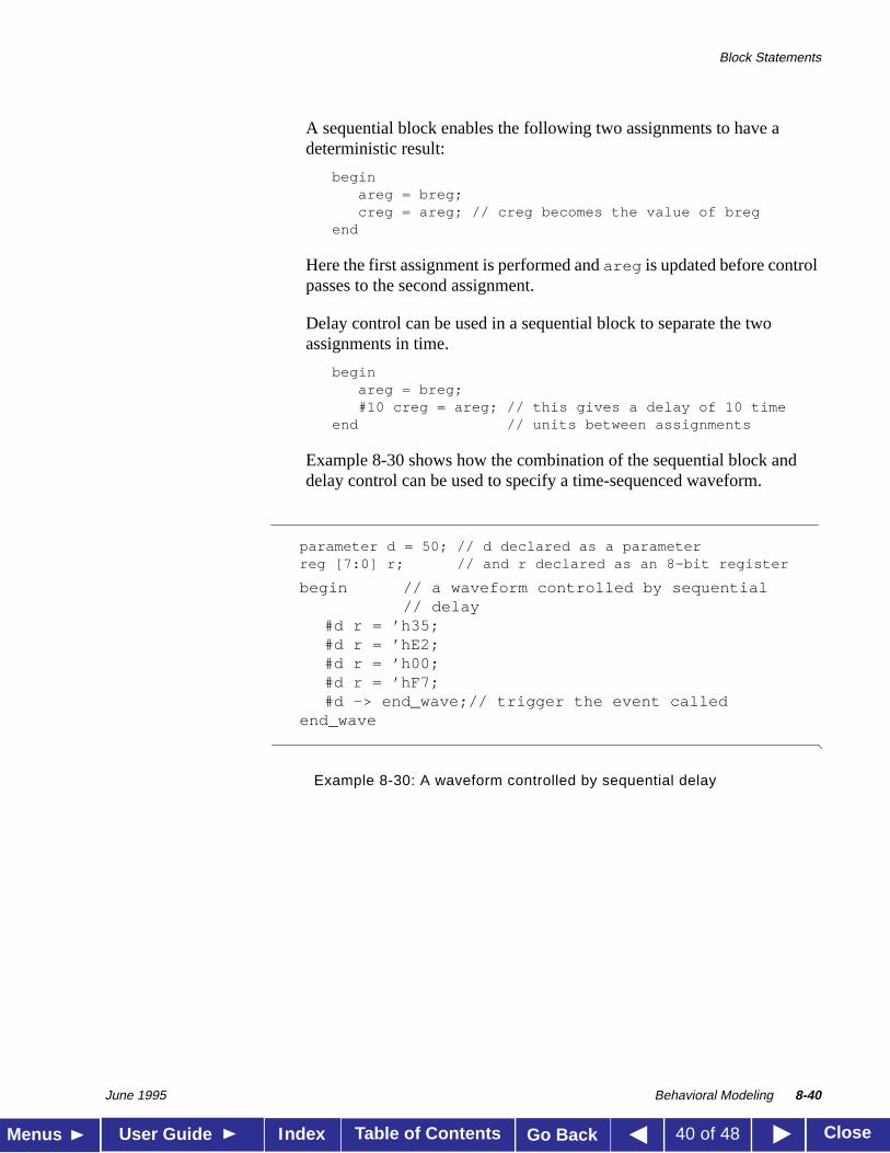
Example 8-30 shows how the combination of the sequential block anddelay control can be used to specify a time-sequenced waveform.
Example 8-30: A waveform controlled by sequential delay
parameter d = 50; // d declared as a parameterreg [7:0] r; // and r declared as an 8-bit register
begin // a waveform controlled by sequential// delay
#d r = ’h35;#d r = ’hE2;#d r = ’h00;#d r = ’hF7;#d -> end_wave;// trigger the event called
end_wave
Block Statements
June 1995 Behavioral Modeling 8-41
Table of Contents CloseMenus User Guide Go BackIndex 41 of 48
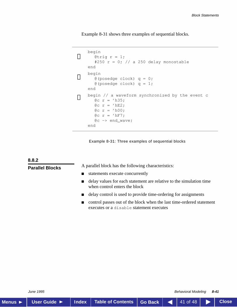
Example 8-31 shows three examples of sequential blocks.
Example 8-31: Three examples of sequential blocks
8.8.2A parallel block has the following characteristics:
■ statements execute concurrently
■ delay values for each statement are relative to the simulation timewhen control enters the block
■ delay control is used to provide time-ordering for assignments
■ control passes out of the block when the last time-ordered statementexecutes or adisable statement executes
begin@trig r = 1;#250 r = 0; // a 250 delay monostable
end
begin@(posedge clock) q = 0;@(posedge clock) q = 1;
end
begin // a waveform synchronized by the event c@c r = ’h35;@c r = ’hE2;@c r = ’h00;@c r = ’hF7;@c -> end_wave;
end
➊
➋
➌
Parallel Blocks
Block Statements
June 1995 Behavioral Modeling 8-42
Table of Contents CloseMenus User Guide Go BackIndex 42 of 48
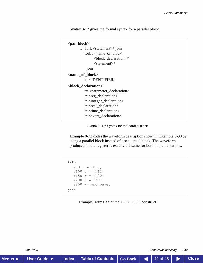
Syntax 8-12 gives the formal syntax for a parallel block.
Syntax 8-12: Syntax for the parallel block
Example 8-32 codes the waveform description shown in Example 8-30 byusing a parallel block instead of a sequential block. The waveformproduced on the register is exactly the same for both implementations.
Example 8-32: Use of the fork-join construct
<par_block>::= fork <statement>* join||= fork : <name_of_block>
<block_declaration>*<statement>*
join
<name_of_block>::= <IDENTIFIER>
<block_declaration>::= <parameter_declaration>||= <reg_declaration>||= <integer_declaration>||= <real_declaration>||= <time_declaration>||= <event_declaration>
fork
#50 r = ’h35;#100 r = ’hE2;#150 r = ’h00;#200 r = ’hF7;#250 -> end_wave;
join
Block Statements
June 1995 Behavioral Modeling 8-43
Table of Contents CloseMenus User Guide Go BackIndex 43 of 48
8.8.3Note that blocks can be named by adding:name_of_block after thekeywordsbegin or fork . The naming of blocks serves several purposes:
■ It allows local variables to be declared for the block.
■ It allows the block to be referenced in statements like thedisablestatement (as discussed in Chapter 10, Disabling of Named Blocks andTasks).
■ In the Verilog language, all variables are static—that is, a uniquelocation exists for all variables and leaving or entering blocks does notaffect the values stored in them.
Thus, block names give a means of uniquely identifying all variables at anysimulation time. This is very important for debugging purposes, where itis necessary to be able to reference a local variable inside a block fromoutside the body of the block.
8.8.4Both forms of blocks have the notion of a start and finish time. Forsequential blocks, the start time is when the first statement is executed, andthe finish time is when the last statement has finished. For parallel blocks,the start time is the same for all the statements, and the finish time is whenthe last time-ordered statement has finished executing. When blocks areembedded within each other, the timing of when a block starts and finishesis important. Execution does not continue to the statement following ablock until the block’s finish time has been reached—that is, until theblock has completely finished executing.
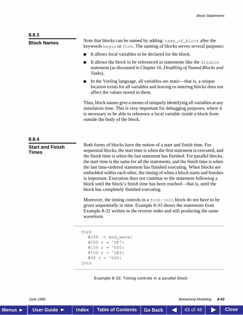
Moreover, the timing controls in afork-join block do not have to begiven sequentially in time. Example 8-33 shows the statements fromExample 8-32 written in the reverse order and still producing the samewaveform.
Example 8-33: Timing controls in a parallel block
Block Names
Start and FinishTimes
fork#250 -> end_wave;#200 r = ’hF7;#150 r = ’h00;#100 r = ’hE2;#50 r = ’h35;
join
Block Statements
June 1995 Behavioral Modeling 8-44
Table of Contents CloseMenus User Guide Go BackIndex 44 of 48
Sequential and parallel blocks can be embedded within each otherallowing complex control structures to be expressed easily and with a highdegree of structure.
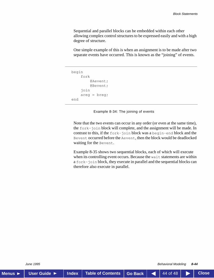
One simple example of this is when an assignment is to be made after twoseparate events have occurred. This is known as the “joining” of events.
Example 8-34: The joining of events
Note that the two events can occur in any order (or even at the same time),thefork-join block will complete, and the assignment will be made. Incontrast to this, if thefork-join block was abegin-end block and theBevent occurred before theAevent , then the block would be deadlockedwaiting for theBevent .
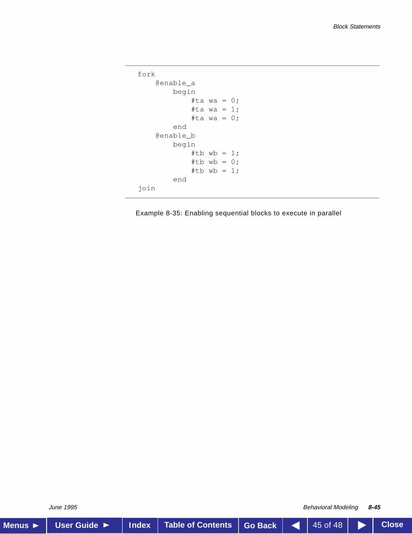
Example 8-35 shows two sequential blocks, each of which will executewhen its controlling event occurs. Because thewait statements are withina fork-join block, they execute in parallel and the sequential blocks cantherefore also execute in parallel.
beginfork
@Aevent;@Bevent;
joinareg = breg;
end
Block Statements
June 1995 Behavioral Modeling 8-45
Table of Contents CloseMenus User Guide Go BackIndex 45 of 48
Example 8-35: Enabling sequential blocks to execute in parallel
fork@enable_a
begin#ta wa = 0;#ta wa = 1;#ta wa = 0;
end@enable_b
begin#tb wb = 1;#tb wb = 0;#tb wb = 1;
endjoin
Examples
June 1995 Behavioral Modeling 8-46
Table of Contents CloseMenus User Guide Go BackIndex 46 of 48
8.9
Examples
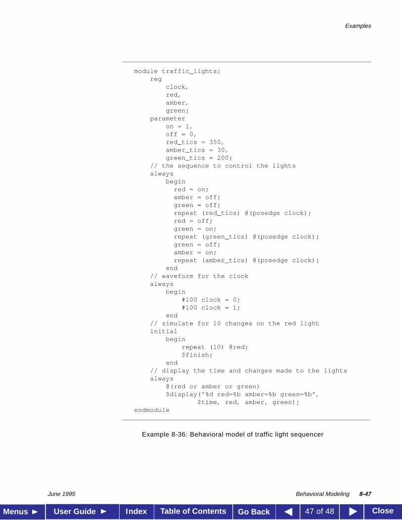
This section contains two behavioral model examples. These examples aregiven as complete descriptions enclosed in modules—such that they can beput directly through the Verilog-XL compiler, simulated and the resultsobserved.
Example 8-36 shows a simple traffic light sequencer described with itsown clock generator.
Examples
June 1995 Behavioral Modeling 8-47
Table of Contents CloseMenus User Guide Go BackIndex 47 of 48
Example 8-36: Behavioral model of traffic light sequencer
module traffic_lights;reg
clock,red,amber,green;
parameteron = 1,off = 0,red_tics = 350,amber_tics = 30,green_tics = 200;
// the sequence to control the lightsalways
beginred = on;amber = off;green = off;repeat (red_tics) @(posedge clock);red = off;green = on;repeat (green_tics) @(posedge clock);green = off;amber = on;repeat (amber_tics) @(posedge clock);
end// waveform for the clockalways
begin#100 clock = 0;#100 clock = 1;
end// simulate for 10 changes on the red lightinitial
beginrepeat (10) @red;$finish;
end// display the time and changes made to the lightsalways
@(red or amber or green)$display("%d red=%b amber=%b green=%b",
$time, red, amber, green);endmodule
Examples
June 1995 Behavioral Modeling 8-48
Table of Contents CloseMenus User Guide Go BackIndex 48 of 48
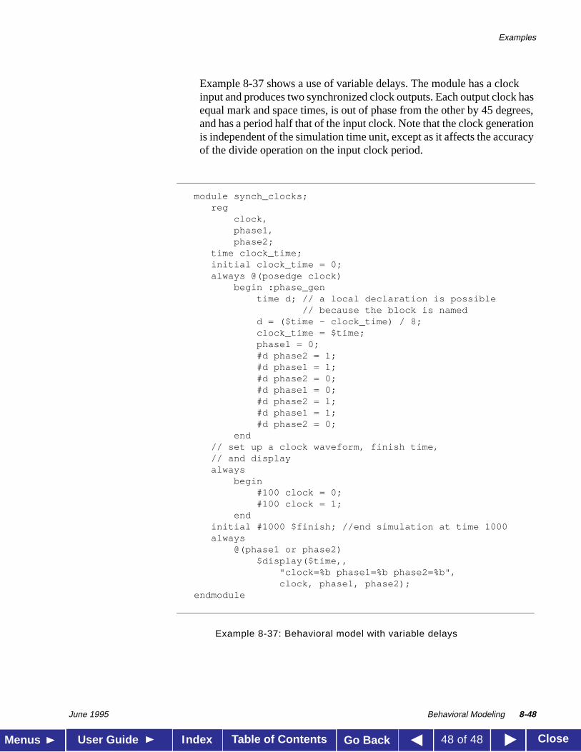
Example 8-37 shows a use of variable delays. The module has a clockinput and produces two synchronized clock outputs. Each output clock hasequal mark and space times, is out of phase from the other by 45 degrees,and has a period half that of the input clock. Note that the clock generationis independent of the simulation time unit, except as it affects the accuracyof the divide operation on the input clock period.
Example 8-37: Behavioral model with variable delays
module synch_clocks;reg
clock,phase1,phase2;
time clock_time;initial clock_time = 0;always @(posedge clock)
begin :phase_gentime d; // a local declaration is possible
// because the block is namedd = ($time - clock_time) / 8;clock_time = $time;phase1 = 0;#d phase2 = 1;#d phase1 = 1;#d phase2 = 0;#d phase1 = 0;#d phase2 = 1;#d phase1 = 1;#d phase2 = 0;
end// set up a clock waveform, finish time,// and displayalways
begin#100 clock = 0;#100 clock = 1;
endinitial #1000 $finish; //end simulation at time 1000always
@(phase1 or phase2)$display($time,,
"clock=%b phase1=%b phase2=%b",clock, phase1, phase2);
endmodule