Embed Size (px)
Citation preview
1
Behaviour and critical failure modes of strip foundations on slopes under 1
seismic and structural loading 2
Dhiraj Raj1, Yogendra Singh2 and Amir M. Kaynia3 3
1Research Scholar, Department of Earthquake Engineering, Indian Institute Technology 4
Roorkee, Roorkee 247-667, India, E-mail: [email protected] 5
2Professor and Head, Department of Earthquake Engineering, Indian Institute Technology 6
Roorkee, Roorkee 247-667, India (corresponding author), E-mail: [email protected] 7
3Technical Expert, Norwegian Geotechnical Institute, P.O. Box 3930 Ullevaal Stadion, 0806 8
Oslo, Norway, E-mail: [email protected] 9
10
Abstract: This paper presents a numerical study on capacity envelopes of strip foundations 11
placed on top and face of two typical soil slopes at different offset distances and subjected to 12
earthquake effects considered using the pseudo-static method. The capacity is estimated using 13
nonlinear 2D finite element limit analysis. Modified swipe and probe analyses are carried out 14
to develop vertical force- moment (V-M) and vertical force- shear force (V-H) capacity 15
envelopes. Characteristic features of these capacity envelopes, and critical failure modes of 16
foundations on slopes are identified and compared with the foundations on flat ground. Relative 17
influence of the soil and structure inertia on capacity envelope of foundation is also explored. 18
It is found that the critical failure mode of a foundation on slope, subjected to gravity and 19
seismic action depends on the effective column height of the structure. A comparison of the 20
capacity envelopes of typical foundations with the corresponding reinforced concrete columns 21
indicates that the foundation design methods of the current building codes cannot avoid 22
premature failure of foundations on slopes, prior to columns. 23
Keywords: Capacity envelope; Slope-foundation interaction; Seismic Loading; Finite element 24
limit analysis (FELA); Capacity design 25
2
Introduction 26
In practice, foundations are often subjected to simultaneous vertical load (V), lateral shear (H) 27
and bending moment (M) generated from the combined action of vertical (gravity) and lateral 28
(wind or earthquake) loads. Most of the current standards and codes of practice (IS6403 1986; 29
EN1997-1 2004; NCHRP 2010) use classical formulation for estimation of bearing capacity of 30
shallow foundations (Terzaghi 1943) and recommend various correction factors to incorporate 31
the effect of shear force and bending moment. The effect of shear force is taken into account 32
with the help of load inclination factor, whereas the effect of bending moment is considered in 33
terms of eccentricity of vertical load from the center of the foundation and through use of an 34
effective width or area of the foundation. However, the capacity of foundations under general 35
planar loading can be better dealt with using capacity envelope (or load interaction) method 36
(Gourvenec and Randolph 2003; Gourvenec 2007a), which explicitly takes into account the 37
interacting load components. This approach has also been incorporated by some of the 38
advanced seismic design codes (EN1998-5 2004; NCHRP 2010; ASCE/SEI41-13 2014) by 39
providing empirical capacity envelopes for some simple cases for foundations on flat ground. 40
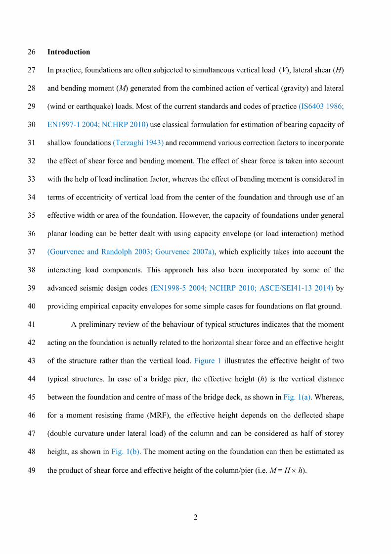
A preliminary review of the behaviour of typical structures indicates that the moment 41
acting on the foundation is actually related to the horizontal shear force and an effective height 42
of the structure rather than the vertical load. Figure 1 illustrates the effective height of two 43
typical structures. In case of a bridge pier, the effective height (h) is the vertical distance 44
between the foundation and centre of mass of the bridge deck, as shown in Fig. 1(a). Whereas, 45
for a moment resisting frame (MRF), the effective height depends on the deflected shape 46
(double curvature under lateral load) of the column and can be considered as half of storey 47
height, as shown in Fig. 1(b). The moment acting on the foundation can then be estimated as 48
the product of shear force and effective height of the column/pier (i.e. M = H h). 49
3
(a) (b)
Fig. 1. Effective height of column/pier in typical structures: (a) A single pier bridge; 50 (b) Moment resisting frame building 51
52
Analytical solutions as well as simple empirical equations are available for the 53
calculation of the failure loads of shallow foundations placed on flat cohesive soil (Ukritchon 54
et al. 1998; Taiebat and Carter 2000; Bransby 2001; Gourvenec and Randolph 2003; Yun and 55
Bransby 2007; Gourvenec 2007a; Gourvenec 2008; Yilmaz and Bakir 2009; Taiebat and Carter 56
2010; Vulpe et al. 2014; Shen et al. 2016; Xiao et al. 2016), and on flat cohesionless soil (Nova 57
and Montrasioa 1991; Gottardi and Butterfield 1993; Butterfield and Gottardi 1994; Gottardi 58
and Butterfield 1995; Montrasioa and Nova 1997; Paolucci and Pecker 1997; Gottardi et al. 59
1999; Houlsby and Cassidy 2002; Loukidis et al. 2008; Krabbenhoft et al. 2012; Kim et al. 60
2014; Kim et al. 2014; Tang et al. 2014; Nguyen et al. 2015). Some experimental studies 61
conducted on shallow foundations subjected to general planer loading have also been reported 62
in the literature (Martin and Houlsby 2000; Govoni et al. 2010; Cocjin and Kusakabe 2013). 63
However, most of the available studies deal with shallow foundations constructed on flat 64
ground consisting of either purely cohesive, or purely cohesionless soils. A few studies are also 65
available on evaluation of capacity envelope for shallow foundations placed on top of a slope. 66
Georgiadis (2010) has performed a parametric study using finite element, upper bound 67
4
plasticity, and stress field methods to examine the influence of a wide range of geometries 68
(slope height, slope angle and normalized foundation distance) on the static capacity envelopes 69
of foundations located on top of slopes. He considered undrained cohesive soil behavior and 70
proposed an empirical equation for the capacity envelope. Baazouzi et al. (2016) conducted a 71
study on vertical-horizontal load interaction diagram of shallow foundations placed on top of 72
cohesionless slopes and found out that the shape of the interaction diagram depends on the 73
slope angle and the distance of the foundation from the slope. 74
It has been found from the available literature that the capacity envelopes have not been 75
studied for: (a) foundations located on face of slopes; (b) slopes consisting of c-ϕ soils; (c) 76
foundations subjected to moment in combination with vertical load; and (d) slope-foundation 77
systems subjected to seismic loading (considering the effect of soil mass inertia). Hence, in this 78
article, an attempt is made to address all the above issues and understand the associated failure 79
mechanisms. To this end, capacity envelopes are developed for strip foundations placed on top 80
and face of the slopes consisting of homogenous c-ϕ soils, and located at different offset 81
distances and subjected to seismic loads in addition to general planar loads. 2D nonlinear Finite 82
Element (FE) models of slopes (of different geometry and soil properties) and foundations (of 83
varying offset distance but fixed width) are developed using OptumG2 (2018) finite element 84
limit analyses (FELA) software. The results thus obtained are presented in the form of 85
normalized V-M and V-H interaction diagrams and are compared to identify the governing 86
failure modes under different combinations of V, H, and M. The influence of effective structural 87
height, offset distance and seismic loading on capacity envelopes and the resulting failure mode 88
are explored in detail. Capacity design is a crucial step in the modern earthquake resistant 89
design practice, which consists of proportioning of different components of structure with a 90
pre-decided hierarchy of strength to achieve a desired yield pattern. In the later part of the 91
present study, capacity envelopes of typical foundations on slopes designed according to 92
5
selected standards and literature are compared with capacity curves of the corresponding 93
reinforced concrete (RC) columns supported on these foundations with the objective of 94
examining the relative hierarchy of strength between typical columns and foundations. 95
96
Problem Statement 97
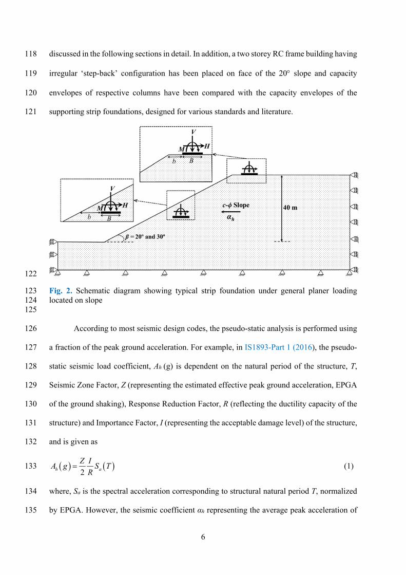
In the present study, two homogeneous slopes having same height (40 m from the slope toe) 98
and inclined at angles, β = 20° and 30° from horizontal, have been considered consisting of dry 99
‘stiff clay’ and ‘dense sand’ soil, respectively, following Fotopoulou and Pitilakis (2013) (see 100
Table 1). The static factor of safety of the 20° and 30° slopes was found to be 2.3 and 2.0, 101
respectively, using finite element limit analyses (FELA) based on strength reduction technique. 102
Both slopes were found to become unstable at a horizontal seismic coefficient, αh ≈ 0.36g 103
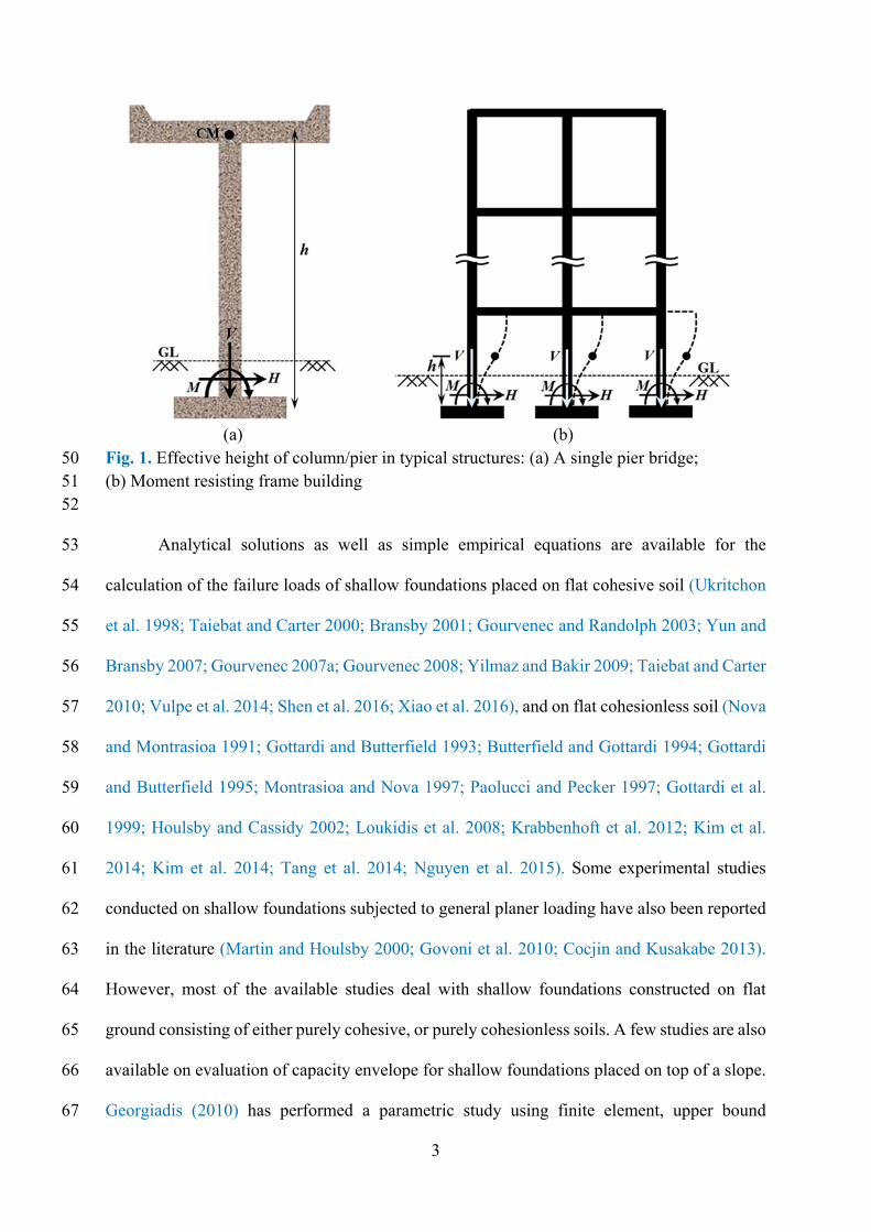
(where, g is acceleration due to gravity) using the pseudo-static approach. A rigid rough strip 104
foundation having width, B = 2 m has been considered on the slopes at two different locations: 105
on top of the slope and at mid-face of the slope as shown in Fig. 2. For the purpose of 106
comparisons, the foundation is also considered to be located on the surface of flat ground with 107
the same soil properties. The figure also shows the strip foundation under the action of 108
combined planar (V, H and M) and seismic loading (αh). The sign convention for applied loads 109
and moment follows inside right hand thumb rule (Butterfield et al. (1997). The foundation has 110
also been considered at three different offsets distances, b/B = 0, 1 and 2, where b is the distance 111
of the foundation edge from the slope face. The strip foundation located at ‘Top’ is placed at 112
the surface of the ground, whereas the strip foundation placed at ‘Mid’ position is embedded 113
in the slope face (Fig. 2). 114
To study the influence of effective column height of structure on the capacity of the 115
foundation, a typical short pier bridge (with effective height = 5.0 m) and a typical RC building 116
with storey height 3.0 m (having effective height = 1.5 m) have been considered (Fig. 1) and 117
6
discussed in the following sections in detail. In addition, a two storey RC frame building having 118
irregular ‘step-back’ configuration has been placed on face of the 20 slope and capacity 119
envelopes of respective columns have been compared with the capacity envelopes of the 120
supporting strip foundations, designed for various standards and literature. 121
122
Fig. 2. Schematic diagram showing typical strip foundation under general planer loading 123 located on slope 124 125
According to most seismic design codes, the pseudo-static analysis is performed using 126
a fraction of the peak ground acceleration. For example, in IS1893-Part 1 (2016), the pseudo-127
static seismic load coefficient, Ah (g) is dependent on the natural period of the structure, T, 128
Seismic Zone Factor, Z (representing the estimated effective peak ground acceleration, EPGA 129
of the ground shaking), Response Reduction Factor, R (reflecting the ductility capacity of the 130
structure) and Importance Factor, I (representing the acceptable damage level) of the structure, 131
and is given as 132
2h a
Z IA g S T
R (1) 133
where, Sa is the spectral acceleration corresponding to structural natural period T, normalized 134
by EPGA. However, the seismic coefficient αh representing the average peak acceleration of 135
7
the soil mass, is usually adopted as half of effective peak ground acceleration (EPGA) at the 136
ground surface (e.g. (EN1998-5 2004; NCHRP 2008). In the present study, the seismic 137
coefficients for both slope and the building have been considered to be equal (i.e. Ah = αh). For 138
a structure, base shear, H and moment, M, is dependent on the seismic weight (= V) and 139
effective height, h, of the structure as given by Eqns. 2 and 3. 140
hH V (2) 141
hM Hh hV (3) 142
143
Table 1. Material properties 144
Properties Stiff Clay Dense Sand
Unit Weight, γ (kN/m3) 20 20
Poisson’s Ratio, ν 0.3 0.3
Cohesion, c (kPa) 50 10
Angle of internal friction, ϕ 27° 44°
145
Modelling and Analysis 146
FELA combines the capabilities of finite element discretization with the plastic bound 147
theorems of limit analysis to bracket the exact limit load by upper and lower bound solutions 148
for handling complex geometries, soil properties, loadings, and boundary conditions 149
(Keawsawasvong and Ukritchon 2017). Application of limit analysis and FELA are extensively 150
discussed by Chen and Liu (1990) and Sloan (2013) for analysing various complex stability 151
problems in geotechnical engineering. The theorems of the limit analysis are valid for a 152
perfectly plastic material with associated flow rule. In addition to LB and UB limit analysis, 153
OptumG2 provides the option of 15-node triangular mixed element from Gauss family, where 154
both the LB and UB problems under plane-strain condition are formulated using second-order 155
cone programming (SOCP) (Makrodimopoulos and Martin 2006; Makrodimopoulos and 156
8
Martin 2007). The details of numerical formulation of FELA used in this study can be found 157
in Krabbenhoft et al. (2016). 158
To understand the failure mechanism and to develop the capacity envelopes, 2D plane-159
strain nonlinear FE model of a slope with strip foundation has been constructed. An elasto-160
plastic constitutive model based on Mohr-Coulomb failure criterion with associated flow rule 161
has been used for soil modeling in FELA. Because the focus is on the capacities, the Mohr-162
Coulomb model is satisfactory. In the present study, the soil mass has been discretized using 163
triangular elements with 15-node mixed Gauss element formulation. The strip foundation has 164
been modelled using plate element. The two-node elastic plate element in plane-strain domain 165
actually acts like the standard Euler-Bernoulli beam element. The strip foundation has been 166
considered as consisting of a rigid elastic material by using relatively large value of Young’s 167
modulus and has been embedded in the soil using interface elements on both sides of the 168
foundation, such that the velocity and stress discontinuities are permitted. The interface 169
properties have been simulated by applying a reduction factor, R to the interface material 170
properties. In the present study, the interface material has been considered the same as the 171
surrounding soil but with zero tension cut-off to allow for gap and uplift and R = 1 to simulate 172
rough foundation. 173
At the base of the FE model, the movements in both directions are restrained, while on 174
the left and right lateral boundaries, only horizontal displacement is restrained. The lateral 175
extent and dimensions of FE model have been evaluated using a sensitivity study, so that the 176
effect of boundary conditions and model dimensions on the domain of interest is negligible. 177
Automatic mesh adaptivity based on shear strain evolution has been employed. Based on a 178
sensitivity and calibration test, five iterations of adaptive meshing with the number of elements 179
increasing from 7000 to 10,000 have been used in all the analyses. To simulate the seismic 180
9
effects on the coupled slope-foundation system, pseudo-static forces have been applied on the 181
entire soil mass in terms of horizontal seismic coefficient, αh. 182
Force controlled ‘swipe’ and constant force-ratio ‘probe’ analyses were carried out to 183
derive capacity envelopes of strip foundation under V-M and V-H load combinations. In both 184
analyses, the forces and moment have been applied at the midpoint of the foundation. In the 185
force controlled swipe test, the foundation was subjected to a vertical load V (varying between 186
0 and V0 at an increment of 0.1V0) and gradually increasing moment till incipient material 187
failure. The plot of the variation of the ultimate moment with V, provides the V-M capacity 188
envelope. In constant force-ratio probe test, the foundation was subjected to vertical, V and 189
horizontal, H, forces gradually increasing in a fixed ratio, till incipient material failure. The 190
ratio V:H was varied between 1:0.05 and 1:1.10, in the successive steps, to obtain the V-H 191
capacity envelope. 192
193
Model Validation and Comparison with Past Studies 194
To validate the adopted plane-strain FE model, normalized static V-H and V-M capacity 195
envelopes for rigid rough strip foundation placed on surface of flat ground have been compared 196
(Fig. 3(a-d)) with those obtained from available standards (EN1998-5 2004; NCHRP 2010) 197
and past studies (Green 1954; Meyerhof 1963; Hansen 1970; Vesić 1975; Butterfield and 198
Gottardi 1994; Paolucci and Pecker 1997; Ukritchon et al. 1998; Loukidis et al. 2008; 199
Gourvenec and Barnett 2011; Tang et al. 2014). The forces (V, H) and moments (M) are 200
normalized by V0 and BV0, respectively, where B is the width of the foundation and V0 is the 201
maximum static vertical load capacity of the foundation placed on flat ground in absence of H 202
and M. The comparison was performed separately for dry cohesionless soil (ϕ = 38° and γ = 20 203
kN/m3) and dry cohesive soil (c = 100 kPa and γ = 20 kN/m3). 204
10
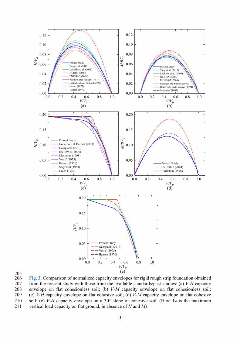
205 Fig. 3. Comparison of normalized capacity envelopes for rigid rough strip foundation obtained 206 from the present study with those from the available standards/past studies: (a) V-H capacity 207 envelope on flat cohesionless soil; (b) V-M capacity envelope on flat cohesionless soil; 208 (c) V-H capacity envelope on flat cohesive soil; (d) V-M capacity envelope on flat cohesive 209 soil; (e) V-H capacity envelope on a 30 slope of cohesive soil. (Here V0 is the maximum 210 vertical load capacity on flat ground, in absence of H and M) 211
0.0 0.2 0.4 0.6 0.8 1.00.00
0.02
0.04
0.06
0.08
0.10
0.12
0.0 0.2 0.4 0.6 0.8 1.00.00
0.02
0.04
0.06
0.08
0.10
0.12
0.0 0.2 0.4 0.6 0.8 1.00.00
0.05
0.10
0.15
0.20
0.0 0.2 0.4 0.6 0.8 1.00.00
0.05
0.10
0.15
0.20
0.0 0.2 0.4 0.6 0.8 1.00.00
0.05
0.10
0.15
0.20
(b)
H/V
0
V/V0
Present Study Tang et al. (2015) Loukidis et al. (2008) NCHRP (2008) EN1998-5 (2004) Paolucci and Pecker (1997) Butterfield and Gottardi (1994) Vesic ́(1975) Hansen (1970)
M/B
V0
V/V0
Present Study Tang et al. (2015) Loukidis et al. (2008) NCHRP (2008) EN1998-5 (2004) Paolucci and Pecker (1997) Butterfield and Gottardi (1994) Meyerhof (1963)
(c)
H/V
0
V/V0
Present Study Gourvenec & Barnett (2011) Georgiadis (2010) EN1998-5 (2004) Ukritchon (1998) Vesic´ (1975) Hansen (1970) Mayerhof (1963) Green (1954)
(e)
(d)
M/B
V0
V/V0
Present Study EN1998-5 (2004) Ukritchon (1998)
H/V
0
V/V0
Present Study Georgiadis (2010) Vesic´ (1975) Hansen (1970)
(a)
11
It is to be noted that all these authors/codes have provided generalized normalized 212
shapes of V-M and V-H capacity envelopes for cohesive and cohesionless soils. Further, 213
Loukidis et al. (2008) have shown that the normalized shape of the capacity envelope is also 214
independent of (associated/non associated) flow rule. In each case, the comparisons were made 215
with as many of the considered studies and standards as possible. Figure 3 (a-e) presents the 216
results of the comparisons and verifications. 217
It is evident from the figure that the present study predicts the capacity envelopes quite 218
close to most of the considered standards/past studies, except Butterfield and Gottardi (1994), 219
which overestimates the capacity for cohesionless soil in both V-M and V-H planes and 220
Ukritchon et al. (1998) which overestimates the V-M capacity for cohesive soil. In addition, 221
the V-H capacity envelope of a rough rigid foundation placed on top of a cohesive soil slope 222
(slope height= 6 m, β = 30°, b/B = 0, c = 100 kPa and γ = 20 kN/m3) has also been compared 223
with the available literature (Hansen 1970; Vesić 1975; Georgiadis 2010) and found to be in 224
good agreement (Fig. 3(e)). 225
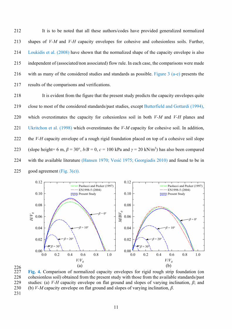
226 Fig. 4. Comparison of normalized capacity envelopes for rigid rough strip foundation (on 227 cohesionless soil) obtained from the present study with those from the available standards/past 228 studies: (a) V-H capacity envelope on flat ground and slopes of varying inclination, β; and 229 (b) V-M capacity envelope on flat ground and slopes of varying inclination, β. 230 231
0.0 0.2 0.4 0.6 0.8 1.00.00
0.02
0.04
0.06
0.08
0.10
0.12
0.0 0.2 0.4 0.6 0.8 1.00.00
0.02
0.04
0.06
0.08
0.10
0.12
(b)
= 30
= 20
= 10
H/V
0
V/V0
Paolucci and Pecker (1997) EN1998-5 (2004) Present Study
= 0
M/B
V0
V/V0
Paolucci and Pecker (1997) EN1998-5 (2004) Present Study
= 30
= 20
= 10
= 0
(a)
12
Among the available literature and codes, only Paolucci and Pecker (1997) and 232
EN1998-5 (2004) consider the effect of earthquake on the capacity envelope. The results of the 233
present study have also been compared (Fig. 4) with those of Paolucci and Pecker (1997) and 234
EN1998-5 (2004) for a rough foundation on cohesionless soil (ϕ = 38° and γ = 20 kN/m3) 235
subjected to αh = 0.10 g. The results obtained using the present study by assuming the 236
foundation to be located on slopes of different inclination (β = 10°, 20° and 30°) have also been 237
compared in the same plots. It should be noted that the available literature and codes do not 238
provide capacity envelopes for foundations on slopes subjected to earthquake action. The 239
comparison in Fig. 4 shows that the present study predicts the capacity envelopes quite close 240
to those by Paolucci and Pecker (1997) and EN1998-5 (2004), also in presence of earthquake 241
action. Further, the figure also illustrates the significance of seismic action in case of 242
foundations located on slopes, and hence the relevance of the present study. 243
244
Results and Discussion 245
Detailed investigation has been conducted to understand the influence of governing parameters 246
such as αh, b/B and effective column height of the structure, h on the capacity envelope. Various 247
failure patterns of the slope-foundation system have been identified in the different considered 248
cases. The critical failure modes at different applied loads have also been identified comparing 249
the V-M and V-H capacity envelopes. In the later part of the numerical study, the critical 250
(governing) capacity envelopes of soil-foundation systems and supported columns, have been 251
compared for a typical reinforced concrete (RC) building resting on a slope. 252
253
Effect of seismic coefficient and offset distance 254
To study the effect of αh and b/B on the capacity, the normalized capacity envelope (M/BV0 vs 255
V/V0 and H/V0 vs V/V0) are plotted for the 20° and 30° slopes and compared with their 256
13
associated results for flat ground conditions. For the considered soil properties, the maximum 257
(vertical) ultimate load, V0 is equal to 3070 kN/m and 11607 kN/m for ‘Stiff clay’ and ‘Dense 258
sand’, respectively. Normalized V-M and V-H diagrams for strip foundation placed on surface 259
of flat ground, and on top and face of the 20° slope are presented in Figs. 5(a, b), 5(c, d) and 260
5(e, f), respectively. Similarly, Figs. 6(a, b), 6(c, d) and 6(e, f), present the normalized V-M 261
and V-H diagrams for strip foundation located on flat ground, and top and face of the 30° slope, 262
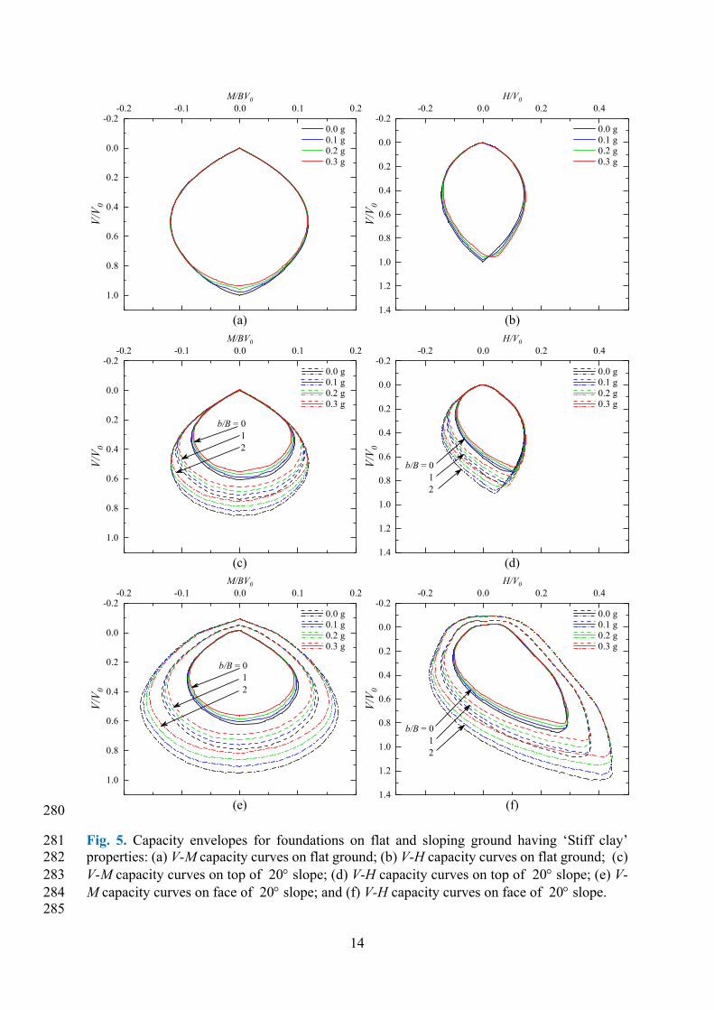
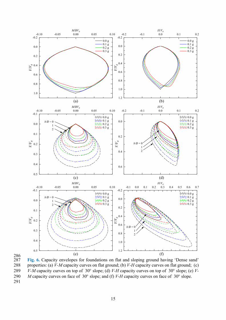
respectively. It is evident from Figs. 5(a, b) and Figs. 6(a, b) that the V-M and V-H capacity 263
envelopes on flat ground, are not much influenced by the variation in αh. On the other hand, in 264
case of foundations on slopes, the V-M and V-H capacity envelopes of the seismic case, become 265
gradually reduced subsets of the respective static case (αh = 0), with increase in αh for a 266
particular b/B, as can be observed from Figs. 5(c-f) and Figs. 6(c-f). It can also be observed 267
that for a particular αh, the V-M and V-H capacity envelopes of a strip foundation with b/B > 0 268
fully encompass the corresponding envelopes of the strip foundation placed at b/B = 0, in all 269
the cases. 270
It can be observed from Figs. 5(c-f) and 6(c-f) that for a particular vertical load, the 271
moment and shear capacities of the foundation towards and away from the slope are 272
significantly different, resulting in asymmetrical V-M and V-H capacity envelopes. However, 273
the degree of asymmetry in V-H envelopes is much more significant and increases with the 274
increase in αh (see Figs. 5(d and f) and 6(d and f)). It is interesting to note that a much higher 275
vertical load (in some cases, even higher than the maximum vertical load capacity in case of 276
flat ground) can be resisted by the foundation on slope, when combined with appropriate value 277
of shear force in the positive (uphill) direction. Further, not one but two values of positive shear 278
force, yield the same vertical load capacity. 279
14
280
Fig. 5. Capacity envelopes for foundations on flat and sloping ground having ‘Stiff clay’ 281 properties: (a) V-M capacity curves on flat ground; (b) V-H capacity curves on flat ground; (c) 282 V-M capacity curves on top of 20 slope; (d) V-H capacity curves on top of 20 slope; (e) V-283 M capacity curves on face of 20 slope; and (f) V-H capacity curves on face of 20 slope. 284 285
-0.2 -0.1 0.0 0.1 0.2-0.2
0.0
0.2
0.4
0.6
0.8
1.0
-0.2 0.0 0.2 0.4-0.2
0.0
0.2
0.4
0.6
0.8
1.0
1.2
1.4
-0.2 -0.1 0.0 0.1 0.2-0.2
0.0
0.2
0.4
0.6
0.8
1.0
-0.2 0.0 0.2 0.4-0.2
0.0
0.2
0.4
0.6
0.8
1.0
1.2
1.4
-0.2 -0.1 0.0 0.1 0.2-0.2
0.0
0.2
0.4
0.6
0.8
1.0
-0.2 0.0 0.2 0.4-0.2
0.0
0.2
0.4
0.6
0.8
1.0
1.2
1.4
(d)
(e) (f)
(c)
(b)
V/V
0M/BV0
0.0 g 0.1 g 0.2 g 0.3 g
V/V
0
H/V0
0.0 g 0.1 g 0.2 g 0.3 g
V/V
0
M/BV0
0.0 g 0.1 g 0.2 g 0.3 g
b/B = 012
V/V
0
H/V0
0.0 g 0.1 g 0.2 g 0.3 g
b/B = 012
V/V
0
M/BV0
0.0 g 0.1 g 0.2 g 0.3 g
b/B = 012
(a)
V/V
0
H/V0
0.0 g 0.1 g 0.2 g 0.3 g
b/B = 012
15
286 Fig. 6. Capacity envelopes for foundations on flat and sloping ground having ‘Dense sand’ 287 properties: (a) V-M capacity curves on flat ground; (b) V-H capacity curves on flat ground; (c) 288 V-M capacity curves on top of 30 slope; (d) V-H capacity curves on top of 30 slope; (e) V-289 M capacity curves on face of 30 slope; and (f) V-H capacity curves on face of 30 slope. 290 291
-0.10 -0.05 0.00 0.05 0.10-0.2
0.0
0.2
0.4
0.6
0.8
1.0
-0.2 -0.1 0.0 0.1 0.2-0.2
0.0
0.2
0.4
0.6
0.8
1.0
1.2
-0.10 -0.05 0.00 0.05 0.10-0.1
0.0
0.1
0.2
0.3
0.4
0.5
-0.2 -0.1 0.0 0.1 0.2
0.0
0.2
0.4
0.6
-0.10 -0.05 0.00 0.05 0.10-0.1
0.0
0.1
0.2
0.3
0.4
0.5
-0.1 0.0 0.1 0.2 0.3 0.4 0.5 0.6 0.7-0.2
0.0
0.2
0.4
0.6
0.8
1.0
1.2
(d)
(e) (f)
(c)
(b)
V/V
0M/BV0
0.0 g 0.1 g 0.2 g 0.3 g
V/V
0
H/V0
0.0 g 0.1 g 0.2 g 0.3 g
V/V
0
M/BV0
0.0 g 0.1 g 0.2 g 0.3 g
b/B = 012
V/V
0
H/V0
0.0 g 0.1 g 0.2 g 0.3 g
b/B = 012
V/V
0
M/BV0
0.0 g 0.1 g 0.2 g 0.3 g
b/B = 012
(a)
V/V
0
H/V0
0.0 g 0.1 g 0.2 g 0.3 g
b/B = 012
16
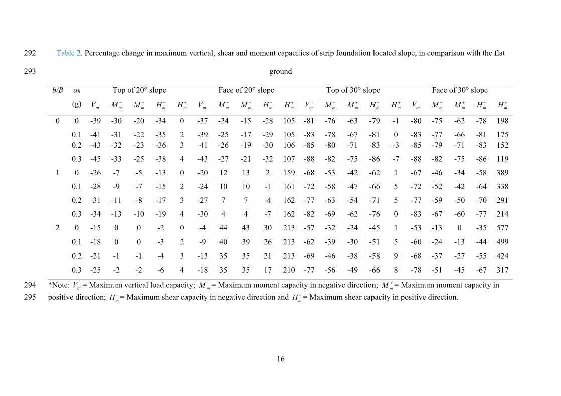
Table 2. Percentage change in maximum vertical, shear and moment capacities of strip foundation located slope, in comparison with the flat 292
ground 293
*Note: mV = Maximum vertical load capacity; mM = Maximum moment capacity in negative direction; mM = Maximum moment capacity in 294
positive direction; mH = Maximum shear capacity in negative direction and mH = Maximum shear capacity in positive direction.295
b/B αh
(g)
Top of 20° slope Face of 20° slope Top of 30° slope Face of 30° slope
mV mM mM mH mH mV mM mM mH mH mV mM mM mH mH mV mM mM mH mH
0 0 -39 -30 -20 -34 0 -37 -24 -15 -28 105 -81 -76 -63 -79 -1 -80 -75 -62 -78 198
0.1 -41 -31 -22 -35 2 -39 -25 -17 -29 105 -83 -78 -67 -81 0 -83 -77 -66 -81 175 0.2 -43 -32 -23 -36 3 -41 -26 -19 -30 106 -85 -80 -71 -83 -3 -85 -79 -71 -83 152
0.3 -45 -33 -25 -38 4 -43 -27 -21 -32 107 -88 -82 -75 -86 -7 -88 -82 -75 -86 119
1 0 -26 -7 -5 -13 0 -20 12 13 2 159 -68 -53 -42 -62 1 -67 -46 -34 -58 389
0.1 -28 -9 -7 -15 2 -24 10 10 -1 161 -72 -58 -47 -66 5 -72 -52 -42 -64 338
0.2 -31 -11 -8 -17 3 -27 7 7 -4 162 -77 -63 -54 -71 5 -77 -59 -50 -70 291
0.3 -34 -13 -10 -19 4 -30 4 4 -7 162 -82 -69 -62 -76 0 -83 -67 -60 -77 214
2 0 -15 0 0 -2 0 -4 44 43 30 213 -57 -32 -24 -45 1 -53 -13 0 -35 577
0.1 -18 0 0 -3 2 -9 40 39 26 213 -62 -39 -30 -51 5 -60 -24 -13 -44 499
0.2 -21 -1 -1 -4 3 -13 35 35 21 213 -69 -46 -38 -58 9 -68 -37 -27 -55 424
0.3 -25 -2 -2 -6 4 -18 35 35 17 210 -77 -56 -49 -66 8 -78 -51 -45 -67 317
17
Table 2 presents the percentage variation in maximum vertical load capacity, mV (in 296
absence of M and H), maximum moment capacity, mM and maximum shear capacity, mH of 297
strip foundation located on top and face of 20° and 30° slopes at different b/B, in comparison 298
with the respective capacities of the surface strip foundation on flat ground. It can be observed 299
from the table that mV and mM reduce by around 35-45% and 15-30%, respectively for the 300
20° slope. Whereas, in case of the 30° slope the corresponding reductions are around 80-90% 301
and 60-80%, respectively. In case of the maximum shear force, mH there is a reduction of 302
about 30-40% in the negative direction and an increase of about 100-200% in the positive 303
direction for 20° slope. In case of the 30° slope the corresponding decrease and increase are as 304
high as about 80-90% and 0-600%, respectively. These results indicate that in case of 305
foundations on slopes, not only the capacity envelopes are asymmetric, the influence of αh and 306
b/B is also asymmetric, resulting in increasingly asymmetric capacity envelopes. 307
308
Failure patterns 309
Figures 7 and 8 show the failure mechanisms for different combinations of vertical load with 310
moment and shear, marked on the normalized V-M and V-H capacity envelopes, respectively. 311
The failure mechanisms are shown for strip foundations embedded at b/B =1 on face of 20° 312
slope and subjected to a seismic coefficient, αh = 0.2g. Similar observations have also been 313
made in all other considered cases (not shown here for brevity). 314
It can also be observed from the figures that the failure mechanism changes 315
continuously with the vertical load. In case of the maximum vertical load (without H and M), 316
the bearing failure with a triangular wedge below the full width of the foundation, takes place. 317
It is similar to the bearing failure on flat ground, except that the failure in case of sloping ground 318
is asymetric and shear wedge forms only in the downhill direction. For the upward (negative) 319
vertical load, a trapezoidal shear wedge is formed providing some capacity against foundation 320
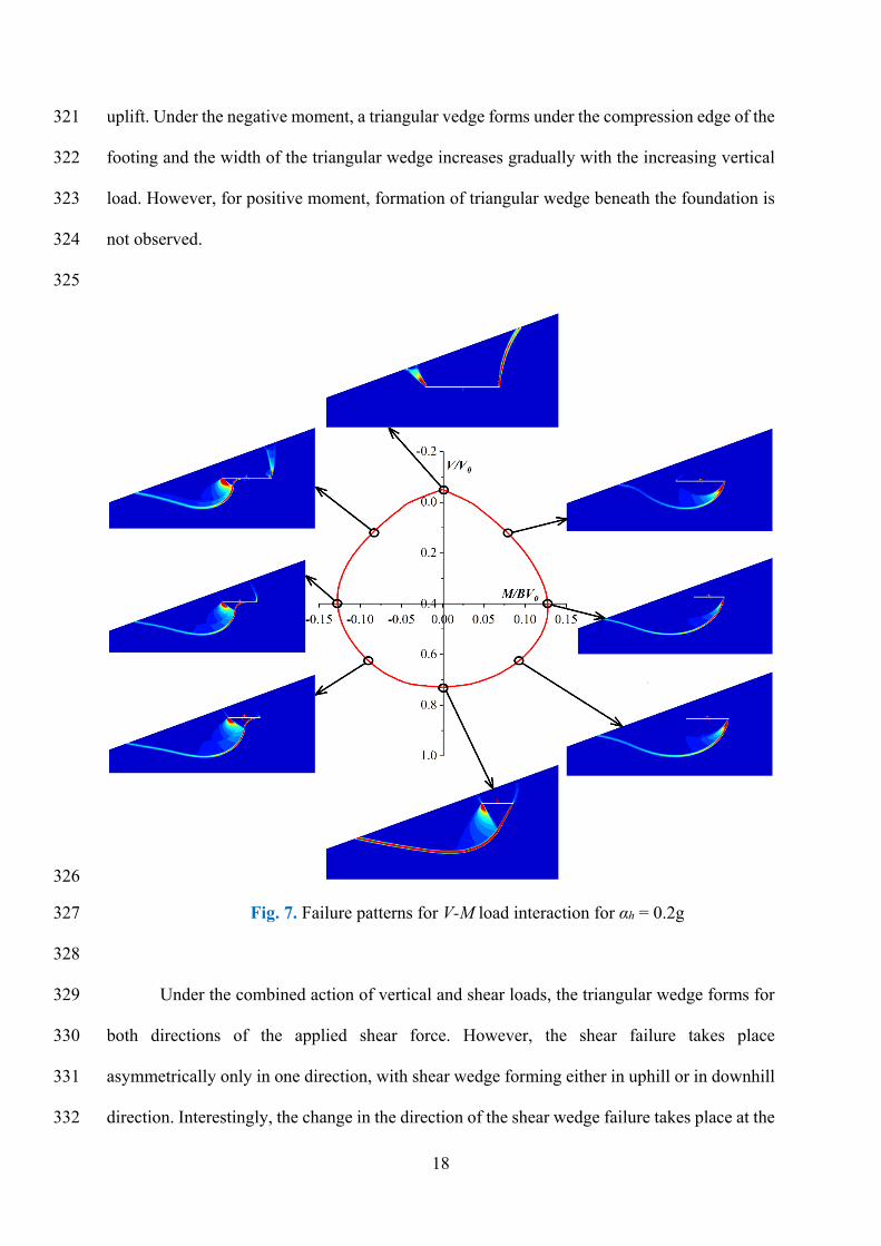
18
uplift. Under the negative moment, a triangular vedge forms under the compression edge of the 321
footing and the width of the triangular wedge increases gradually with the increasing vertical 322
load. However, for positive moment, formation of triangular wedge beneath the foundation is 323
not observed. 324
325
326
Fig. 7. Failure patterns for V-M load interaction for αh = 0.2g 327
328
Under the combined action of vertical and shear loads, the triangular wedge forms for 329
both directions of the applied shear force. However, the shear failure takes place 330
asymmetrically only in one direction, with shear wedge forming either in uphill or in downhill 331
direction. Interestingly, the change in the direction of the shear wedge failure takes place at the 332
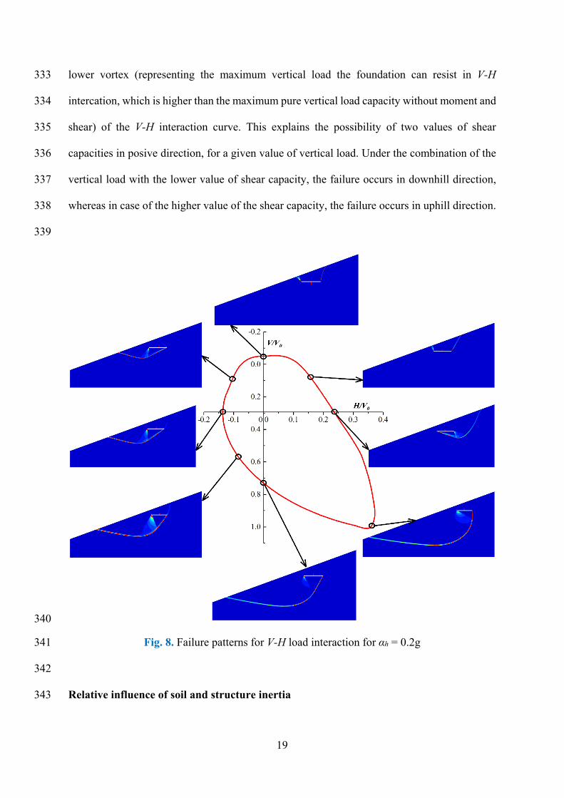
19
lower vortex (representing the maximum vertical load the foundation can resist in V-H 333
intercation, which is higher than the maximum pure vertical load capacity without moment and 334
shear) of the V-H interaction curve. This explains the possibility of two values of shear 335
capacities in posive direction, for a given value of vertical load. Under the combination of the 336
vertical load with the lower value of shear capacity, the failure occurs in downhill direction, 337
whereas in case of the higher value of the shear capacity, the failure occurs in uphill direction. 338
339
340
Fig. 8. Failure patterns for V-H load interaction for αh = 0.2g 341
342
Relative influence of soil and structure inertia 343
20
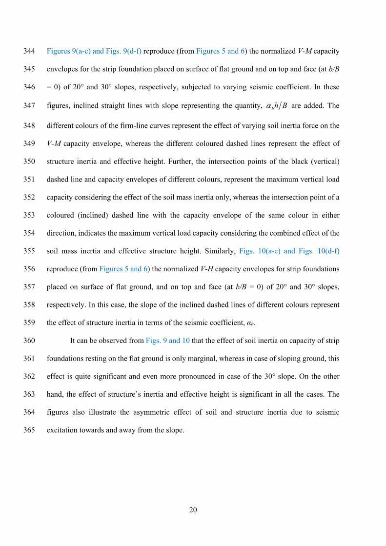
Figures 9(a-c) and Figs. 9(d-f) reproduce (from Figures 5 and 6) the normalized V-M capacity 344
envelopes for the strip foundation placed on surface of flat ground and on top and face (at b/B 345
= 0) of 20° and 30° slopes, respectively, subjected to varying seismic coefficient. In these 346
figures, inclined straight lines with slope representing the quantity, h Bh are added. The 347
different colours of the firm-line curves represent the effect of varying soil inertia force on the 348
V-M capacity envelope, whereas the different coloured dashed lines represent the effect of 349
structure inertia and effective height. Further, the intersection points of the black (vertical) 350
dashed line and capacity envelopes of different colours, represent the maximum vertical load 351
capacity considering the effect of the soil mass inertia only, whereas the intersection point of a 352
coloured (inclined) dashed line with the capacity envelope of the same colour in either 353
direction, indicates the maximum vertical load capacity considering the combined effect of the 354
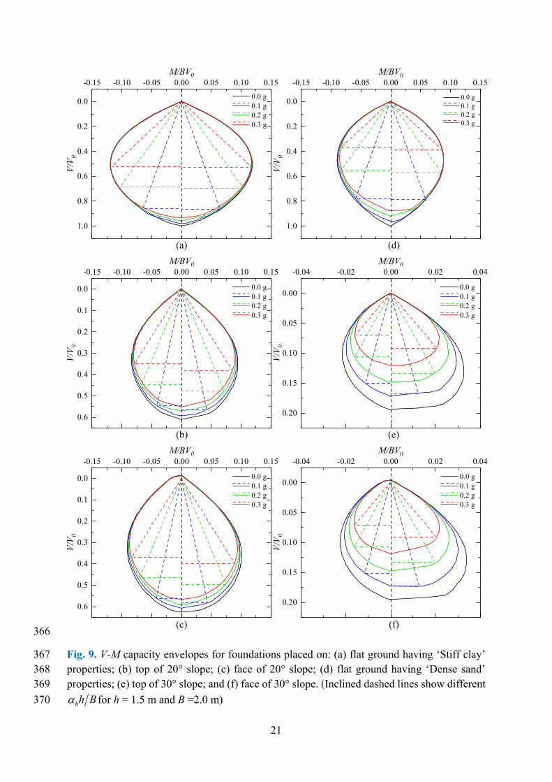
soil mass inertia and effective structure height. Similarly, Figs. 10(a-c) and Figs. 10(d-f) 355
reproduce (from Figures 5 and 6) the normalized V-H capacity envelopes for strip foundations 356
placed on surface of flat ground, and on top and face (at b/B = 0) of 20° and 30° slopes, 357
respectively. In this case, the slope of the inclined dashed lines of different colours represent 358
the effect of structure inertia in terms of the seismic coefficient, αh. 359
It can be observed from Figs. 9 and 10 that the effect of soil inertia on capacity of strip 360
foundations resting on the flat ground is only marginal, whereas in case of sloping ground, this 361
effect is quite significant and even more pronounced in case of the 30° slope. On the other 362
hand, the effect of structure’s inertia and effective height is significant in all the cases. The 363
figures also illustrate the asymmetric effect of soil and structure inertia due to seismic 364
excitation towards and away from the slope. 365
21
366
Fig. 9. V-M capacity envelopes for foundations placed on: (a) flat ground having ‘Stiff clay’ 367 properties; (b) top of 20° slope; (c) face of 20° slope; (d) flat ground having ‘Dense sand’ 368 properties; (e) top of 30° slope; and (f) face of 30° slope. (Inclined dashed lines show different369
h Bh for h = 1.5 m and B =2.0 m) 370
-0.15 -0.10 -0.05 0.00 0.05 0.10 0.15
0.0
0.2
0.4
0.6
0.8
1.0
-0.15 -0.10 -0.05 0.00 0.05 0.10 0.15
0.0
0.2
0.4
0.6
0.8
1.0
-0.15 -0.10 -0.05 0.00 0.05 0.10 0.15
0.0
0.1
0.2
0.3
0.4
0.5
0.6
-0.04 -0.02 0.00 0.02 0.04
0.00
0.05
0.10
0.15
0.20
-0.15 -0.10 -0.05 0.00 0.05 0.10 0.15
0.0
0.1
0.2
0.3
0.4
0.5
0.6
-0.04 -0.02 0.00 0.02 0.04
0.00
0.05
0.10
0.15
0.20
(f)(c)
(e)(b)
(d)
V/V
0M/BV0
0.0 g 0.1 g 0.2 g 0.3 g
V/V
0
M/BV0
0.0 g 0.1 g 0.2 g 0.3 g
V/V
0
M/BV0
0.0 g 0.1 g 0.2 g 0.3 g
V/V
0
M/BV0
0.0 g 0.1 g 0.2 g 0.3 g
V/V
0
M/BV0
0.0 g 0.1 g 0.2 g 0.3 g
V/V
0
M/BV0
0.0 g 0.1 g 0.2 g 0.3 g
(a)
22
371
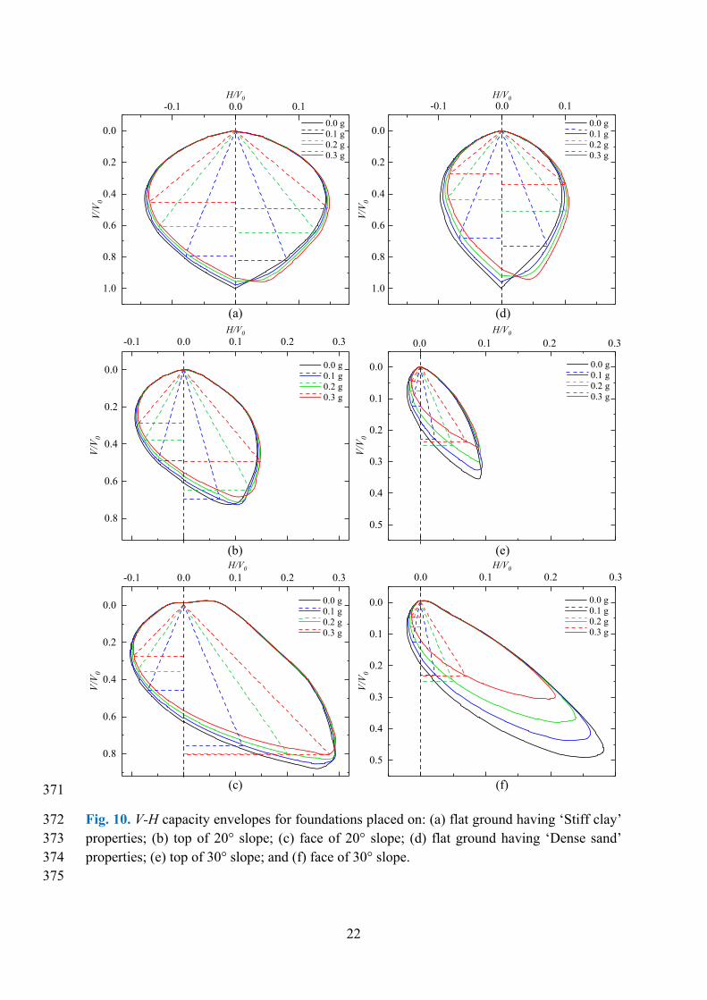
Fig. 10. V-H capacity envelopes for foundations placed on: (a) flat ground having ‘Stiff clay’ 372 properties; (b) top of 20° slope; (c) face of 20° slope; (d) flat ground having ‘Dense sand’ 373 properties; (e) top of 30° slope; and (f) face of 30° slope. 374
375
-0.1 0.0 0.1
0.0
0.2
0.4
0.6
0.8
1.0
-0.1 0.0 0.1
0.0
0.2
0.4
0.6
0.8
1.0
-0.1 0.0 0.1 0.2 0.3
0.0
0.2
0.4
0.6
0.8
0.0 0.1 0.2 0.3
0.0
0.1
0.2
0.3
0.4
0.5
-0.1 0.0 0.1 0.2 0.3
0.0
0.2
0.4
0.6
0.8
0.0 0.1 0.2 0.3
0.0
0.1
0.2
0.3
0.4
0.5
V/V
0H/V0
0.0 g 0.1 g 0.2 g 0.3 g
(e)
V/V
0
H/V0
0.0 g 0.1 g 0.2 g 0.3 g
V/V
0
H/V0
0.0 g 0.1 g 0.2 g 0.3 g
(b)
(d)
(c)
V/V
0
H/V0
0.0 g 0.1 g 0.2 g 0.3 g
V/V
0
H/V0
0.0 g 0.1 g 0.2 g 0.3 g
(a)
(f)
V/V
0
H/V0
0.0 g 0.1 g 0.2 g 0.3 g
23
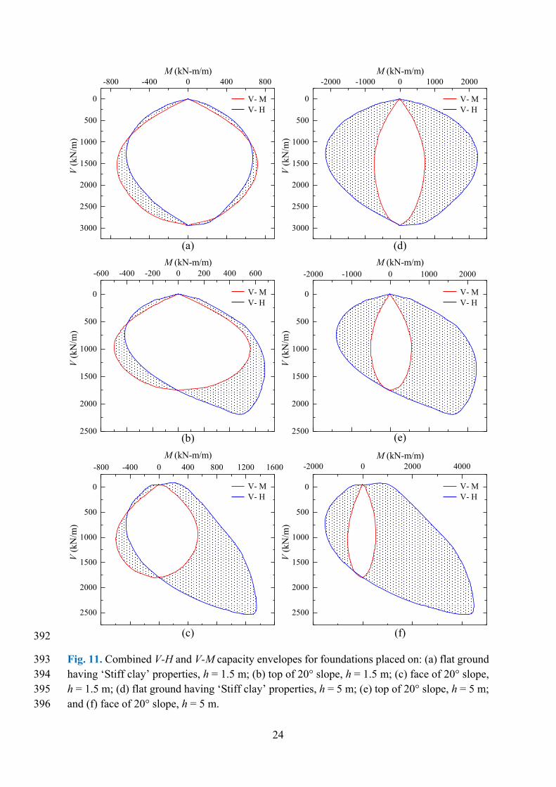
Critical failure mode and governing capacity envelope 376
To identify the critical failure mode, the V-M capacity envelopes have been compared (Fig. 11) 377
with the corresponding V-H capacity for a strip foundation located on surface of flat ground, 378
and on top and face (at b/B =0) of 20° slope subjected to αh = 0.20g. To facilitate direct 379
comparison, the shear capacity has also been expressed in terms of equivalent moment, by 380
multiplying with effective height. Figures 11(a-c) show the capacity envelopes for h = 1.5 m, 381
representing a typical building with storey height = 3 m, whereas Figures 11(d-f) show the 382
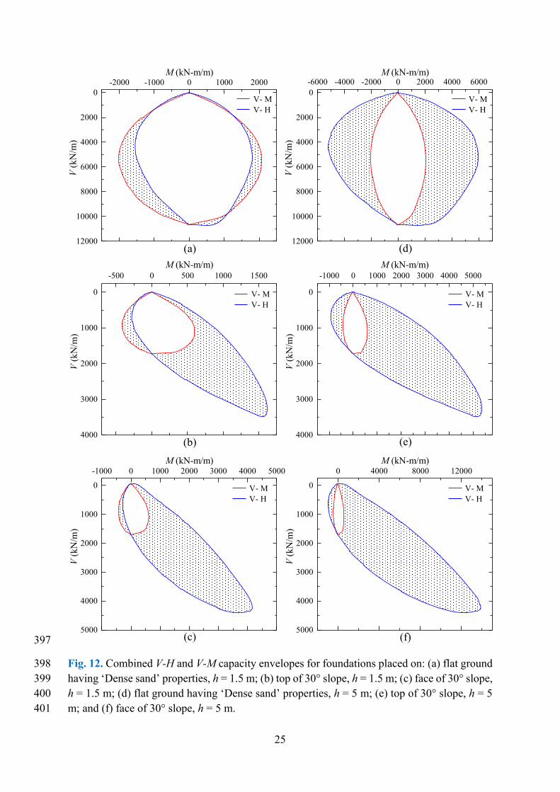
capacity envelopes for h = 5 m, representing a short pier bridge. Similarly, Fig. 12 shows the 383
comparison of the capacity envelopes for the 30° slope. The red coloured curves in the figures, 384
indicate the moment capacity and the blue coloured curves indicate the shear capacity. 385
It can be observed from Figs. 11 (a-c) and 12(a-c) that in the positive direction, the 386
failure is governed by the moment capacity, for both the slopes and both the effective heights, 387
whereas, in the negative direction, the failure of the strip foundation depends on V and h. In 388
case of shorter structures (h = 1.5 m), the failure is governed by shear capacity for lower values 389
of V, whereas in case of taller structures (h = 5 m) and for higher values of V, even in case of 390
shorter structures, the failure is governed by the moment capacity. 391
24
392
Fig. 11. Combined V-H and V-M capacity envelopes for foundations placed on: (a) flat ground 393 having ‘Stiff clay’ properties, h = 1.5 m; (b) top of 20° slope, h = 1.5 m; (c) face of 20° slope, 394 h = 1.5 m; (d) flat ground having ‘Stiff clay’ properties, h = 5 m; (e) top of 20° slope, h = 5 m; 395 and (f) face of 20° slope, h = 5 m. 396
-800 -400 0 400 800
0
500
1000
1500
2000
2500
3000
-2000 -1000 0 1000 2000
0
500
1000
1500
2000
2500
3000
-600 -400 -200 0 200 400 600
0
500
1000
1500
2000
2500
-2000 -1000 0 1000 2000
0
500
1000
1500
2000
2500
-800 -400 0 400 800 1200 1600
0
500
1000
1500
2000
2500
-2000 0 2000 4000
0
500
1000
1500
2000
2500
V- M V- H
(d)
V (
kN/m
)M (kN-m/m)
(a)
V- M V- H
V (
kN/m
)
M (kN-m/m)
V- M V- H
(e)
V (
kN/m
)
M (kN-m/m)
(b)
V- M V- H
V (
kN/m
)
M (kN-m/m)
V- M V- H
(f)
V (
kN/m
)
M (kN-m/m)
(c)
V- M V- H
V (
kN/m
)
M (kN-m/m)
25
397
Fig. 12. Combined V-H and V-M capacity envelopes for foundations placed on: (a) flat ground 398 having ‘Dense sand’ properties, h = 1.5 m; (b) top of 30° slope, h = 1.5 m; (c) face of 30° slope, 399 h = 1.5 m; (d) flat ground having ‘Dense sand’ properties, h = 5 m; (e) top of 30° slope, h = 5 400 m; and (f) face of 30° slope, h = 5 m. 401
-2000 -1000 0 1000 20000
2000
4000
6000
8000
10000
12000
-6000 -4000 -2000 0 2000 4000 60000
2000
4000
6000
8000
10000
12000
-500 0 500 1000 1500
0
1000
2000
3000
4000
-1000 0 1000 2000 3000 4000 5000
0
1000
2000
3000
4000
-1000 0 1000 2000 3000 4000 5000
0
1000
2000
3000
4000
5000
0 4000 8000 12000
0
1000
2000
3000
4000
5000
V- M V- H
(d)
V (
kN/m
)M (kN-m/m)
(a)
V- M V- H
V (
kN/m
)
M (kN-m/m)
V- M V- H
(e)
V (
kN/m
)
M (kN-m/m)
(b)
V- M V- H
V (
kN/m
)
M (kN-m/m)
V- M V- H
(f)
V (
kN/m
)
M (kN-m/m)
(c)
V- M V- H
V (
kN/m
)
M (kN-m/m)
26
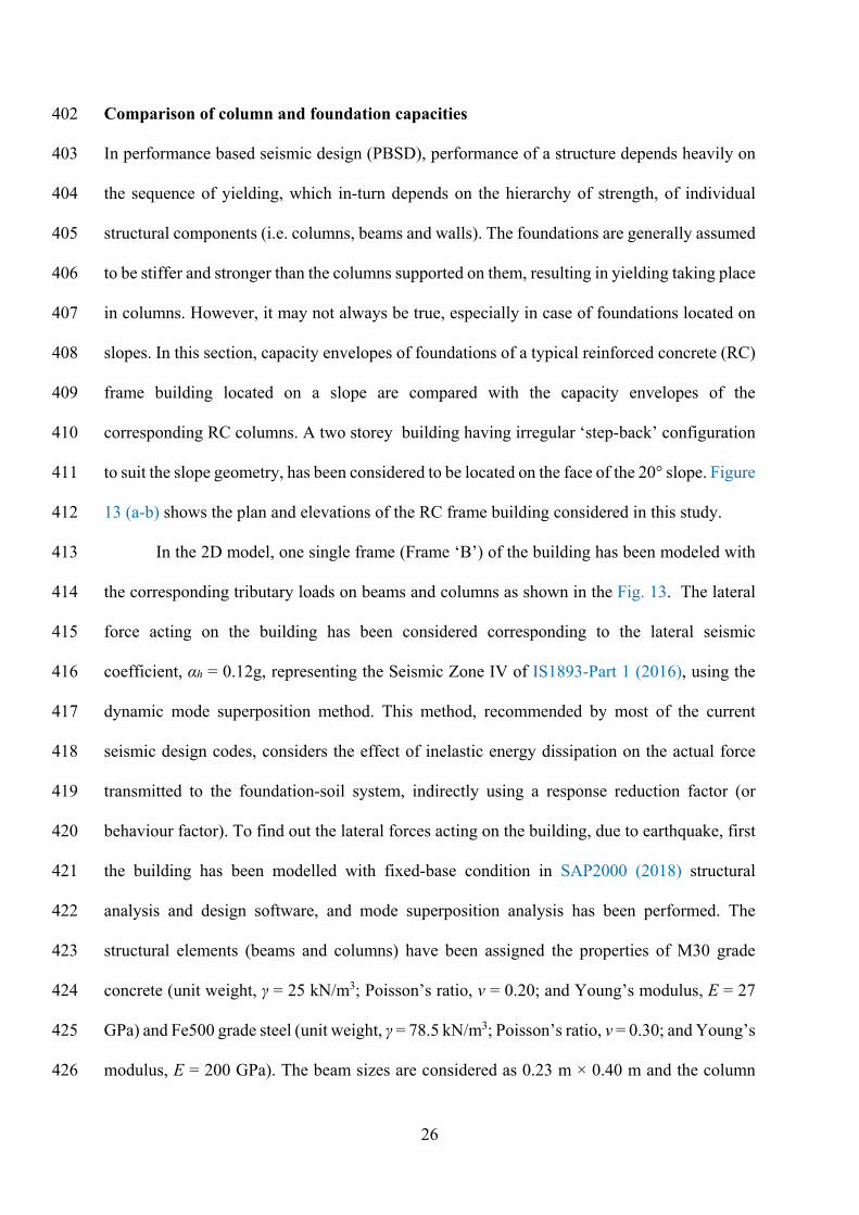
Comparison of column and foundation capacities 402
In performance based seismic design (PBSD), performance of a structure depends heavily on 403
the sequence of yielding, which in-turn depends on the hierarchy of strength, of individual 404
structural components (i.e. columns, beams and walls). The foundations are generally assumed 405
to be stiffer and stronger than the columns supported on them, resulting in yielding taking place 406
in columns. However, it may not always be true, especially in case of foundations located on 407
slopes. In this section, capacity envelopes of foundations of a typical reinforced concrete (RC) 408
frame building located on a slope are compared with the capacity envelopes of the 409
corresponding RC columns. A two storey building having irregular ‘step-back’ configuration 410
to suit the slope geometry, has been considered to be located on the face of the 20° slope. Figure 411
13 (a-b) shows the plan and elevations of the RC frame building considered in this study. 412
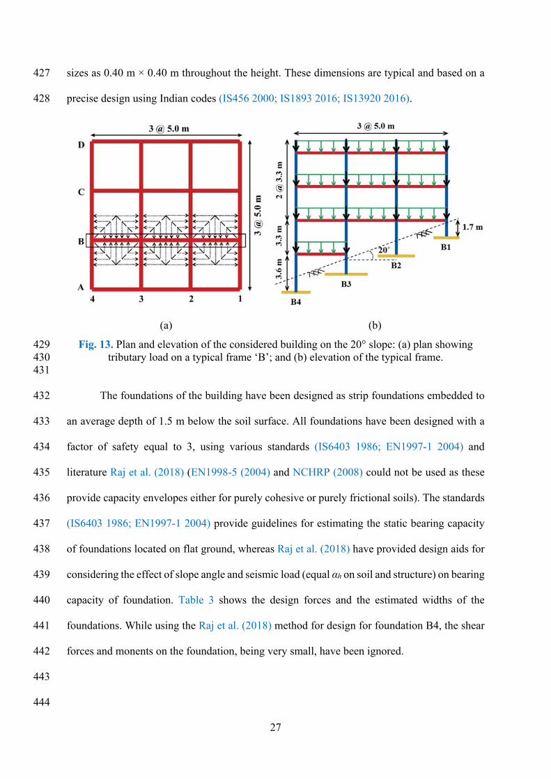
In the 2D model, one single frame (Frame ‘B’) of the building has been modeled with 413
the corresponding tributary loads on beams and columns as shown in the Fig. 13. The lateral 414
force acting on the building has been considered corresponding to the lateral seismic 415
coefficient, αh = 0.12g, representing the Seismic Zone IV of IS1893-Part 1 (2016), using the 416
dynamic mode superposition method. This method, recommended by most of the current 417
seismic design codes, considers the effect of inelastic energy dissipation on the actual force 418
transmitted to the foundation-soil system, indirectly using a response reduction factor (or 419
behaviour factor). To find out the lateral forces acting on the building, due to earthquake, first 420
the building has been modelled with fixed-base condition in SAP2000 (2018) structural 421
analysis and design software, and mode superposition analysis has been performed. The 422
structural elements (beams and columns) have been assigned the properties of M30 grade 423
concrete (unit weight, γ = 25 kN/m3; Poisson’s ratio, ν = 0.20; and Young’s modulus, E = 27 424
GPa) and Fe500 grade steel (unit weight, γ = 78.5 kN/m3; Poisson’s ratio, ν = 0.30; and Young’s 425
modulus, E = 200 GPa). The beam sizes are considered as 0.23 m × 0.40 m and the column 426
27
sizes as 0.40 m × 0.40 m throughout the height. These dimensions are typical and based on a 427
precise design using Indian codes (IS456 2000; IS1893 2016; IS13920 2016). 428
(a) (b)
Fig. 13. Plan and elevation of the considered building on the 20° slope: (a) plan showing 429 tributary load on a typical frame ‘B’; and (b) elevation of the typical frame. 430
431
The foundations of the building have been designed as strip foundations embedded to 432
an average depth of 1.5 m below the soil surface. All foundations have been designed with a 433
factor of safety equal to 3, using various standards (IS6403 1986; EN1997-1 2004) and 434
literature Raj et al. (2018) (EN1998-5 (2004) and NCHRP (2008) could not be used as these 435
provide capacity envelopes either for purely cohesive or purely frictional soils). The standards 436
(IS6403 1986; EN1997-1 2004) provide guidelines for estimating the static bearing capacity 437
of foundations located on flat ground, whereas Raj et al. (2018) have provided design aids for 438
considering the effect of slope angle and seismic load (equal αh on soil and structure) on bearing 439
capacity of foundation. Table 3 shows the design forces and the estimated widths of the 440
foundations. While using the Raj et al. (2018) method for design for foundation B4, the shear 441
forces and monents on the foundation, being very small, have been ignored. 442
443
444
28
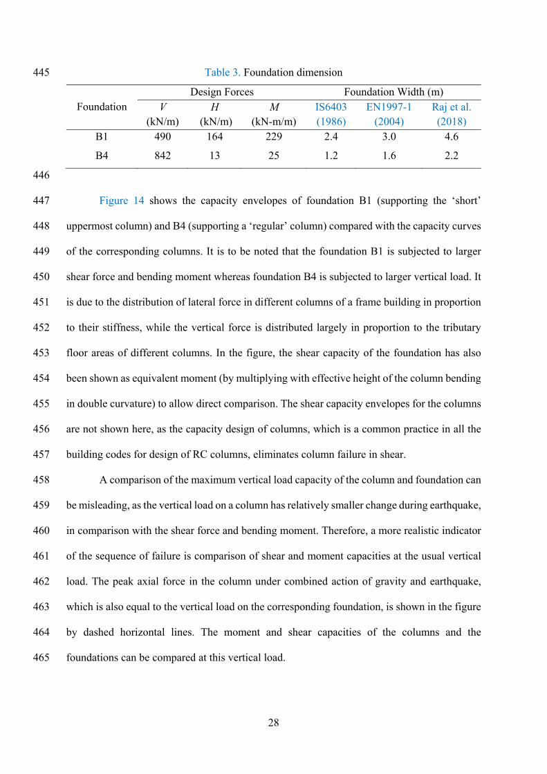
Table 3. Foundation dimension 445
Foundation Design Forces Foundation Width (m)
V (kN/m)
H (kN/m)
M (kN-m/m)
IS6403 (1986)
EN1997-1 (2004)
Raj et al. (2018)
B1 490 164 229 2.4 3.0 4.6
B4 842 13 25 1.2 1.6 2.2
446
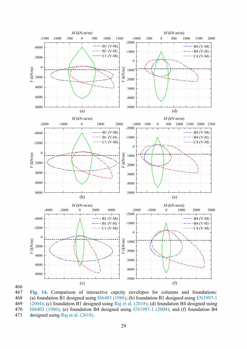
Figure 14 shows the capacity envelopes of foundation B1 (supporting the ‘short’ 447
uppermost column) and B4 (supporting a ‘regular’ column) compared with the capacity curves 448
of the corresponding columns. It is to be noted that the foundation B1 is subjected to larger 449
shear force and bending moment whereas foundation B4 is subjected to larger vertical load. It 450
is due to the distribution of lateral force in different columns of a frame building in proportion 451
to their stiffness, while the vertical force is distributed largely in proportion to the tributary 452
floor areas of different columns. In the figure, the shear capacity of the foundation has also 453
been shown as equivalent moment (by multiplying with effective height of the column bending 454
in double curvature) to allow direct comparison. The shear capacity envelopes for the columns 455
are not shown here, as the capacity design of columns, which is a common practice in all the 456
building codes for design of RC columns, eliminates column failure in shear. 457
A comparison of the maximum vertical load capacity of the column and foundation can 458
be misleading, as the vertical load on a column has relatively smaller change during earthquake, 459
in comparison with the shear force and bending moment. Therefore, a more realistic indicator 460
of the sequence of failure is comparison of shear and moment capacities at the usual vertical 461
load. The peak axial force in the column under combined action of gravity and earthquake, 462
which is also equal to the vertical load on the corresponding foundation, is shown in the figure 463
by dashed horizontal lines. The moment and shear capacities of the columns and the 464
foundations can be compared at this vertical load. 465
29
466 Fig. 14. Comparison of interactive capcity envelopes for columns and foundations: 467 (a) foundation B1 designed using IS6403 (1986); (b) foundation B1 designed using EN1997-1 468 (2004); (c) foundation B1 designed using Raj et al. (2018); (d) foundation B4 designed using 469 IS6403 (1986); (e) foundation B4 designed using EN1997-1 (2004); and (f) foundation B4 470 designed using Raj et al. (2018). 471
-1500 -1000 -500 0 500 1000 1500
-4000
-2000
0
2000
4000
6000
8000
-1000 -500 0 500 1000 1500 2000-2000
-1000
0
1000
2000
3000
4000
5000
-2000 -1000 0 1000 2000
-4000
-2000
0
2000
4000
6000
8000
-1000 -500 0 500 1000 1500 2000 2500-2000
-1000
0
1000
2000
3000
4000
5000
-4000 -2000 0 2000 4000
-4000
-2000
0
2000
4000
6000
8000
-2000 -1000 0 1000 2000 3000-2000
-1000
0
1000
2000
3000
4000
5000
B1 (V-M) B1 (V-H) C1 (V-M)
V (
kN/m
)M (kN-m/m)
B4 (V-M) B4 (V-H) C4 (V-M)
(f)
(e)
(d)
V (
kN/m
)
M (kN-m/m)
B1 (V-M) B1 (V-H) C1 (V-M)
(c)
(b)
V (
kN/m
)
M (kN-m/m)
B4 (V-M) B4 (V-H) C4 (V-M)
V (
kN/m
)M (kN-m/m)
B1 (V-M) B1 (V-H) C1 (V-M)
V (
kN/m
)
M (kN-m/m)
B4 (V-M) B4 (V-H) C4 (V-M)
V (
kN/m
)
M (kN-m/m)
(a)
30
Figure 14 shows that while moment capacity of the foundations is higher than the 472
capacity of the corresponding columns, in all the considered cases, the shear capacity of 473
foundation B1 designed as per IS6403 (1986) and EN1997-1 (2004) is much lower than the 474
capacity of the corresponding column. This indicates that during a strong seismic event, the 475
foundation will fail in shear prior to flexural yielding of the column. Interestingly, the shear 476
capacity of foundation B1 designed as per Raj et al. (2018) is close to the capacity of the 477
corresponding column. However, this closeness is also coincidental, as the design using this 478
method does take into account the effect of slope and shear due to αh, but the design 479
methodology for RC members and foundations being different, results in different amounts of 480
over-strength (reserve strength). 481
482
Conclusions 483
A numerical study has been performed to understand the behaviour and failure modes of strip 484
foundation placed at different locations on stable slopes, subjected to seismic loading including 485
inertial effect of soil mass. The behaviour and capacity envelopes of strip foundations placed 486
on slopes, under general planar loading, have been compared with their counterpart soil-487
foundation systems on flat ground. Contrary to the symmetric failure mechanism of strip 488
foundations on flat ground, distinctly different failure mechanisms have been observed for the 489
strip foundations placed on the slopes under different directions of seismic excitation. This 490
effect is also reflected by the asymmetry in the V-M and V-H capacity envelopes and is more 491
prominent with increasing slope angles. It is interesting to note that the foundations on slope 492
can resist higher vertical loads when applied in combination with appropriate magnitude of 493
shear force acting in positive (towards slope) direction. Further, for this vertical load ( mV ) 494
there exist two values of positive shear corresponding to two different failure modes. 495
31
The study has clearly brought out the two different effects (i.e. due to soil inertia and 496
due to structure inertia) of earthquake action, on foundation capacity. In case of the flat ground 497
and moderate (20°) slope, the effect of soil inertia is only marginal but the effect of structure 498
inertia is quite significant, whereas in case of steeper (30°) slope, both the effects are quite 499
significant. 500
The shear capacity of foundations on slopes, in positive direction, being much higher, 501
the failure is invariably governed by moment. However in case of negative direction, the 502
effective height of the structure and amount of vertical load govern the failure mode. 503
A comparison of the capacity envelopes of the foundations and corresponding RC 504
columns indicates that the conventionally designed foundations (without considering the 505
effects of slope and soil and structure inertia forces, on the bearing capacity) are expected to 506
fail before yielding of the RC columns. This is contrary to the commonly used philosophy of 507
capacity design, in which the plastic hinges are assumed to form in the superstructure. 508
509
Acknowledgments 510
The research work presented here was supported by the Institute fellowship to the first author 511
from the Ministry of Human Resource Development, Government of India. The authors are 512
grateful to ‘Optum Computational Engineering’ (OptumCE) for providing free academic 513
license of OptumG2 software to perform the present study. 514
515
References 516
ASCE/SEI41-13 (2014). "Seismic Evaluation and Retrofit of Existing Buildings." American 517
Society of Civil Engineers, Reston, Virginia. 518
32
Baazouzi, M., Benmeddour, D., Mabrouki, A., and Mellas, M. (2016). "2D Numerical Analysis 519
of Shallow Foundation Rested Near Slope under Inclined Loading." Procedia 520
Engineering, 143, 623-634. 521
Bransby, M. F. (2001). "Failure envelopes and plastic potentials for eccentrically loaded 522
surface footings on undrained soil." International Journal for Numerical and Analytical 523
Methods in Geomechanics, 25(4), 329-346. 524
Butterfield, R., and Gottardi, G. (1994). "A complete three-dimensional failure envelope for 525
shallow footings on sand." Géotechnique, 44(1), 181-184. 526
Butterfield, R., and Gottardi, G. (1994). "Plastic response of circular footings on sand under 527
general planar loading." Géotechnique, 44(1), 181-184. 528
Butterfield, R., Houlsby, G. T., and Gottardi, G. (1997). "Standardized sign conventions and 529
notation for generally loaded foundations." Géotechnique, 47(5), 1051-1054. 530
Chen, W. F., and Liu, X. L. (1990). Limit analysis in soil mechanics, Elsevier, Amsterdam. 531
Cocjin, M., and Kusakabe, O. (2013). "Centrifuge observations on combined loading of a strip 532
footing on dense sand." Géotechnique, 63(5), 427-433. 533
EN1997-1 (2004). "Eurocode 7: Geotechnical design - Part 1: General rules." British Standards 534
Institution, London. 535
EN1998-5 (2004). "Design Provisions for Earthquake Resistance of Structures- Part 5: 536
Foundations, retaining structures and geotechnical aspects." British Standards 537
Institution, London. 538
Fotopoulou, S. D., and Pitilakis, K. D. (2013). "Fragility curves for reinforced concrete 539
buildings to seismically triggered slow-moving slides." Soil Dynamics and Earthquake 540
Engineering, 48, 143-161. 541
Georgiadis, K. (2010). "The influence of load inclination on the undrained bearing capacity of 542
strip footings on slopes." Computers and Geotechnics, 37(3), 311-322. 543
33
Gottardi, G., and Butterfield, R. O. Y. (1993). "On the bearing capacity of surface footings on 544
sand under general planar loads." Soils and Foundations, 33(3), 68-79. 545
Gottardi, G., and Butterfield, R. O. Y. (1995). "The displacement of a model rigid surface 546
footing on dense sand under general planar loading." Soils and Foundations, 35(3), 71-547
82. 548
Gottardi, G., Houlsby, G. T., and Butterfield, R. (1999). "Plastic response of circular footings 549
on sand under general planar loading." Géotechnique, 49(4), 453-469. 550
Gourvenec, S. (2007a). "Shape effects on the capacity of rectangular footings under general 551
loading." Géotechnique, 57(8), 637-646. 552
Gourvenec, S. (2008). "Effect of embedment on the undrained capacity of shallow foundations 553
under general loading." Géotechnique, 58(3), 177-185. 554
Gourvenec, S., and Barnett, S. (2011). "Undrained failure envelope for skirted foundations 555
under general loading." Géotechnique, 61(3), 263-270. 556
Gourvenec, S., and Randolph, M. (2003). "Effect of strength non-homogeneity on the shape of 557
failure envelopes for combined loading of strip and circular foundations on clay." 558
Géotechnique, 53(6), 575-586. 559
Govoni, L., Gourvenec, S., and Gottardi, G. (2010). "Centrifuge modelling of circular shallow 560
foundations on sand." International Journal of Physical Modelling in Geotechnics, 561
10(2), 35-46. 562
Green, A. P. (1954). "The plastic yielding of metal junctions due to combined shear and 563
pressure." Journal of the Mechanics and Physics of Solids, 2(3), 197-211. 564
Hansen, J. B. (1970). "A revised and extended formula for bearing capacity." Bulletin no. 28, 565
Danish Geotechnical Institute, Copenhagen, 5-11. 566
Houlsby, G. T., and Cassidy, M. J. (2002). "A plasticity model for the behaviour of footings 567
on sand under combined loading." Géotechnique, 55(2), 117-129. 568
34
IS456 (2000). "Plain and Reinforced Concrete - Code of Practice." Bureau of Indian Standard, 569
New Delhi. 570
IS1893 (2016). "Crieteria for Eathquake Resistance Design of Structures, Part 1 General 571
Provisons and Buildings ", Bureau of Indian Standard, New Delhi. 572
IS6403 (1986). "Code of Practice for Determination of Bearing Capacity of Shallow 573
Foundations."Bureau of Indian Standards, New Delhi. 574
IS13920 (2016). "Ductile Detailing of Reinforced Concrete Structures Subjected to Seismic 575
Forces - Code of Practice." Bureau of Indian Standard, New Delhi. 576
Keawsawasvong, S., and Ukritchon, B. (2017). "Undrained limiting pressure behind soil gaps 577
in contiguous pile walls." Computers and Geotechnics, 83, 152-158. 578
Kim, D., Youn, J., Jee, S., Choi, J., Lee, J., and Choo, Y. (2014). "Numerical studies on 579
combined VH loading and inclination factor of circular footings on sand." Journal of 580
the Korean Geotechical Society, 30(3), 29-46. 581
Kim, D., Youn, J., Jee, S., and Choo, Y. (2014). "Numerical studies on combined VM loading 582
and eccentricity factor of circular footings on sand." Journal of the Korean Geotechical 583
Society, 30(3), 59-72. 584
Krabbenhoft, K., Lyamin, A., and Krabbenhoft, J. (2016). OptumG2: Theory, Optum 585
Computational Engineering, Available on: www.optumce.com. 586
Krabbenhoft, S., Damkilde, L., and Krabbenhoft, K. (2012). "Lower-bound calculations of the 587
bearing capacity of eccentrically loaded footings in cohesionless soil." Canadian 588
Geotechnical Journal, 49(3), 298-310. 589
Loukidis, D., Chakraborty, T., and Salgado, R. (2008). "Bearing capacity of strip footings on 590
purely frictional soil under eccentric and inclined loads." Canadian Geotechnical 591
Journal, 45(6), 768-787. 592
35
Makrodimopoulos, A., and Martin, C. M. (2006). "Lower bound limit analysis of cohesive-593
frictional materials using second-order cone programming." International Journal for 594
Numerical Methods in Engineering, 66(4), 604-634. 595
Makrodimopoulos, A., and Martin, C. M. (2007). "Upper bound limit analysis using simplex 596
strain elements and second-order cone programming." International Journal for 597
Numerical and Analytical Methods in Geomechanics, 31(6), 835-865. 598
Martin, C. M., and Houlsby, G. T. (2000). "Combined loading of spudcan foundations on clay: 599
laboratory tests." Géotechnique, 50(4), 325-338. 600
Meyerhof, G. G. (1963). "Some recent research on the bearing capacity of foundations." 601
Canadian Geotechnical Journal, 1(1), 16-26. 602
Montrasioa, L., and Nova, R. (1997). "Settlements of shallow foundations on sand: 603
Geometrical effects." Géotechnique, 47(1), 49-60. 604
NCHRP (2008). "Report 611: Seismic Analysis and Design of Retaining Walls, Buried 605
Structures, Slopes, and Embankments." National Cooperative Highway Research 606
Program, Transportation Research Board, Washington, D.C. 607
NCHRP (2010). "Report 651: LRFD Design and Construction of Shallow Foundations for 608
Highway Bridge Structures." National Cooperative Highway Research Program, 609
Transportation Research Board, Washington, D.C. 610
Nguyen, D. L., Ohtsuka, S., and Kaneda, K. (2015). "Ultimate bearing capacity of footing on 611
sandy soil against combined load of vertical, horizontal and moment loads." Fifth 612
International Conference on Geotechnique, Construction Materials and Environment, 613
Osaka, Japan. 614
Nova, R., and Montrasioa, L. (1991). "Settlements of shallow foundations on sand." 615
Géotechnique, 41(2), 243-256. 616
OptumG2. 2018. Optum Computational Engineering, Copenhagen NV, Denmark. 617
36
Paolucci, R., and Pecker, A. (1997). "Seismic bearing capacity of shallow strip foundations on 618
dry soils." Soils and Foundations, 37(3), 95-105. 619
Raj, D., Singh, Y., and Shukla, S. K. (2018). "Seismic bearing capacity of strip foundation 620
embedded in c-ϕ soil slope." International Journal of Geomechanics, 18(7). 621
SAP2000. 2018. Computers and Structures Inc., Berkeley. 622
Shen, Z., Feng, X., and Gourvenec, S. (2016). "Undrained capacity of surface foundations with 623
zero-tension interface under planar V-H-M loading." Computers and Geotechnics, 73, 624
47-57. 625
Sloan, S. W. (2013). "Geotechnical stability analysis." Géotechnique, 63(7), 531-572. 626
Taiebat, H. A., and Carter, J. P. (2000). "Numerical studies of the bearing capacity of shallow 627
foundations on cohesive soil subjected to combined loading." Géotechnique, 50(4), 628
409-418. 629
Taiebat, H. A., and Carter, J. P. (2010). "A failure surface for circular footings on cohesive 630
soils." Géotechnique, 60(4), 265-273. 631
Tang, C., Phoon, K.-K., and Toh, K.-C. (2014). "Effect of footing width on Nγ and failure 632
envelope of eccentrically and obliquely loaded strip footings on sand." Canadian 633
Geotechnical Journal, 52(6), 694-707. 634
Terzaghi, K. (1943). Theoretical soil mechanics, John Wiley & Sons, Inc., New York, USA. 635
Ukritchon, B., Whittle, A. J., and Sloan, S. W. (1998). "Undrained Limit Analyses for 636
Combined Loading of Strip Footings on Clay." Journal of Geotechnical and 637
Geoenvironmental Engineering, 124(3), 265-276. 638
Vesić, A. S. (1975). "Bearing capacity of shallow foundations." Foundation Engineering 639
Handbook, 1st edition, H. F. Winterkorn, and H. Y. Fang, eds., Chapter 3, Van 640
Nostrand Reinhold Company, Inc., New York, 121-147. 641

37
Vulpe, C., Gourvenec, S., and Power, M. (2014). "A generalised failure envelope for undrained 642
capacity of circular shallow foundations under general loading." Géotechnique Letters, 643
4(3), 187-196. 644
Xiao, Z., Tian, Y., and Gourvenec, S. (2016). "A practical method to evaluate failure envelopes 645
of shallow foundations considering soil strain softening and rate effects." Applied 646
Ocean Research, 59(Supplement C), 395-407. 647
Yilmaz, M. T., and Bakir, B. S. (2009). "Capacity of shallow foundations on saturated 648
cohesionless soils under combined loading." Canadian Geotechnical Journal, 46(6), 649
639-649. 650
Yun, G., and Bransby, M. F. (2007). "The horizontal-moment capacity of embedded 651
foundations in undrained soil." Canadian Geotechnical Journal, 44(4), 409-424. 652
653