Embed Size (px)
Citation preview
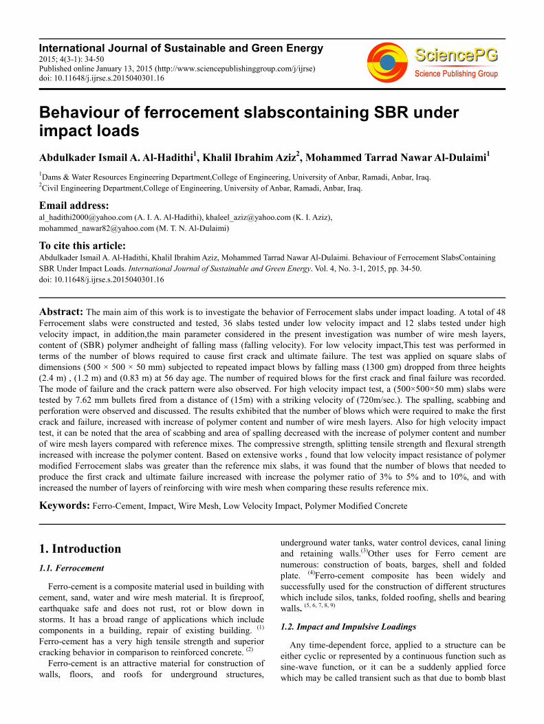
International Journal of Sustainable and Green Energy 2015; 4(3-1): 34-50
Published online January 13, 2015 (http://www.sciencepublishinggroup.com/j/ijrse)
doi: 10.11648/j.ijrse.s.2015040301.16
Behaviour of ferrocement slabscontaining SBR under impact loads
Abdulkader Ismail A. Al-Hadithi1, Khalil Ibrahim Aziz
2, Mohammed Tarrad Nawar Al-Dulaimi
1
1Dams & Water Resources Engineering Department,College of Engineering, University of Anbar, Ramadi, Anbar, Iraq.
2Civil Engineering Department,College of Engineering, University of Anbar, Ramadi, Anbar, Iraq.
Email address:
[email protected] (A. I. A. Al-Hadithi), [email protected] (K. I. Aziz),
[email protected] (M. T. N. Al-Dulaimi)
To cite this article: Abdulkader Ismail A. Al-Hadithi, Khalil Ibrahim Aziz, Mohammed Tarrad Nawar Al-Dulaimi. Behaviour of Ferrocement SlabsContaining
SBR Under Impact Loads. International Journal of Sustainable and Green Energy. Vol. 4, No. 3-1, 2015, pp. 34-50.
doi: 10.11648/j.ijrse.s.2015040301.16
Abstract: The main aim of this work is to investigate the behavior of Ferrocement slabs under impact loading. A total of 48
Ferrocement slabs were constructed and tested, 36 slabs tested under low velocity impact and 12 slabs tested under high
velocity impact, in addition,the main parameter considered in the present investigation was number of wire mesh layers,
content of (SBR) polymer andheight of falling mass (falling velocity). For low velocity impact,This test was performed in
terms of the number of blows required to cause first crack and ultimate failure. The test was applied on square slabs of
dimensions (500 × 500 × 50 mm) subjected to repeated impact blows by falling mass (1300 gm) dropped from three heights
(2.4 m) , (1.2 m) and (0.83 m) at 56 day age. The number of required blows for the first crack and final failure was recorded.
The mode of failure and the crack pattern were also observed. For high velocity impact test, a (500×500×50 mm) slabs were
tested by 7.62 mm bullets fired from a distance of (15m) with a striking velocity of (720m/sec.). The spalling, scabbing and
perforation were observed and discussed. The results exhibited that the number of blows which were required to make the first
crack and failure, increased with increase of polymer content and number of wire mesh layers. Also for high velocity impact
test, it can be noted that the area of scabbing and area of spalling decreased with the increase of polymer content and number
of wire mesh layers compared with reference mixes. The compressive strength, splitting tensile strength and flexural strength
increased with increase the polymer content. Based on extensive works , found that low velocity impact resistance of polymer
modified Ferrocement slabs was greater than the reference mix slabs, it was found that the number of blows that needed to
produce the first crack and ultimate failure increased with increase the polymer ratio of 3% to 5% and to 10%, and with
increased the number of layers of reinforcing with wire mesh when comparing these results reference mix.
Keywords: Ferro-Cement, Impact, Wire Mesh, Low Velocity Impact, Polymer Modified Concrete
1. Introduction
1.1. Ferrocement
Ferro-cement is a composite material used in building with
cement, sand, water and wire mesh material. It is fireproof,
earthquake safe and does not rust, rot or blow down in
storms. It has a broad range of applications which include
components in a building, repair of existing building. (1)
Ferro-cement has a very high tensile strength and superior
cracking behavior in comparison to reinforced concrete. (2)
Ferro-cement is an attractive material for construction of
walls, floors, and roofs for underground structures,
underground water tanks, water control devices, canal lining
and retaining walls.(3)
Other uses for Ferro cement are
numerous: construction of boats, barges, shell and folded
plate. (4)
Ferro-cement composite has been widely and
successfully used for the construction of different structures
which include silos, tanks, folded roofing, shells and bearing
walls. (5, 6, 7, 8, 9)
1.2. Impact and Impulsive Loadings
Any time-dependent force, applied to a structure can be
either cyclic or represented by a continuous function such as
sine-wave function, or it can be a suddenly applied force
which may be called transient such as that due to bomb blast
International Journal of Sustainable and Green Energy 2015; 4(3-1): 34-50 35
or impact loading.
The term (impulsive load) refers to the complete force-
time history applied to the structure, which is likely to be
independent of the properties of the structure as in the case
of bomb blast loading. Impact may be defined as the process
of collision of two bodies which occurs in a very short
interval of time during which the two bodies exert on each
other relatively large forces, called impact loads, which
depend on velocity, mass, shape, elastic and plastic
properties of the collided bodies.
The problem of impacts caused by natural collisions onto
concrete structure has to be given proper considerations.
Examples of such cases and also the related classifications
are listed in Table (1) (10)
below.
Impacts on concrete structures can normally be classified
into two different groups, namely soft impact and hard
impact:
� Soft impact: causes deformation to the striking body.
Propagation of stress waves is negligible and the
failure mechanism is quite similar to that of the static
failure.
� Hard impact: Barely any deformation forms on the
striking body. Impact velocity is high in this case, thus
complicated stress waves can be expected to be the
main cause of failure.
A realistic analysis of an impact loading situation is in
general complex due to many non- linearity involved. Before
the development of high speed computers, this analysis was
performed with approximations, which closely related to a
given experimental test situation. (11)
Table 1. Type of impact (10)
Single impulsive blow
Example of impact phenomena Type of impact
Vehicular collisions onto handrails of expressways or freeways. Soft
Ship or vehicular collisions onto bridge piers. Soft
Ship collision onto offshore structures or gravity platforms for oil extraction. Soft
Aircraft collision onto nuclear power plants. Soft
Cars hitting columns in multistory car parks. Soft
Explosions on concrete structures. Hard
Repeated (multiple)
impulsive blows
Blows from car tires across expansion joints. Soft
Rocks falling onto roof of protection shelters in mountainous regions. Soft
Blows on concrete piles during hydraulic piling. Soft / Hard
Ship or iceberg brushing against offshore structures or gravity platforms. Soft
Meteorites falling onto concrete lunar structures (in future). Soft
1.3. Latex modified concrete (LMC)
Latex is a polymer system consisting of very small (0.05-1
µm Dia.) spherical particles of high molecular weight
polymers held suspension in water by the use of surface
active agents. Adding of polymer Latex to concrete can
improve strength, ductility and durability. The latex is
essentially a bonding agent which can be mixed integrally
with the concrete and gives it superior adhesive properties.
Polymer latex modification of cement mortar and concrete is
governed by the cement hydration and polymer film
formation processes in their binder phase.
In order to rise the tensile strength of cement mortar and
concrete by the addition of epoxies, a series of experiments
had been carried out by Sauer (12)
whose study demonstrated
that with (15%) weight polymer added to concrete, both
tensile and compressive strength are appreciably increased.
The following results were obtained from this study:
� With increased resin content, there is not only strength
improvement but also decreased water absorption and
increased toughness and energy absorbing ability.
� In the case of concrete, these strength improvements
can be realized by addition of (15%) weight polymer to
the concrete while, at same time, proportionately
reduced the water content to maintain comparable
slump. Reducing the water-cement ratio causes
improvement in compressive strength.
� Strength improvement of the order of 100 % possible in
both mortar and concrete specimens by adding of
appropriate amounts of polymer to the mix.
An investigation was carried out by Ohama(13)
to show the
weather ability of adhesion of polymer modified mortars to
ordinary mortars by exposing specimens to normal
weathering conditions for 10 years. He found that the
polymer adhesion characteristic increases with time.
1.3.1. Styrene Butadiene Rubber (SBR)
SBR polymer is most widely used in concrete. The
proportion of SBR latex, combined with low water /cement
ratio produces concrete that has improved flexural, tensile,
bond strength, lower modulus of elasticity and reduced
permeability characteristics compared with conventional
concrete of similar mix design. Compressive strength is
typically unchanged. (14)
Folice et al(15)
, tested (180) concrete samples, different in
size and shape. All properties of modified concrete were
analyzed depending on the quantity of polymer used. The
following results were obtained from the tests:
� The greater effect on physical and mechanical
properties of latex modified concrete was achieved at
the optimal combination of wet and dry curing, i.e.,
curing in dry environment.
� Compressive strength was slightly increased with the
increase of polymer/cement ratio (1 to 7 percent).
� Tensile strength increased with the increase of
polymer/cement.
36 Abdulkader Ismail A. Al-Hadithi et al.: Behaviour of Ferrocement SlabsContaining SBR Under Impact Loads
� Ratio and the correlation is in the form of a straight line.
The increase of flexural strength for concrete modified
with 7.5 percent of polymer admixture was (40) percent
in relation to the reference concrete.
� Water absorption decreased with the increase of
polymer/cement ratio.
� Shrinkage of the modified concrete with 7.5 percent of
polymer admixture on the cement mass was almost 50
percent less than the shrinkage of the reference
concrete.
� Adhesion between reinforcement and concrete
increases with the polymer/cement ratio increase.
� The effect of latex quantity of 7.5 percent on the
cement mass has not significantly influenced the value
of static and dynamic modules of elasticity.
The ACI Committee 544 (16)
repeated drop - weight
apparatus which was designed to compare the relative merits
different fiber-concrete mixtures and demonstrate the
improved performance fiber-concrete compared with
conventional concrete. It can also be adapted to show the
relative impact resistance of different material thicknesses. In
the ACI test, a 4.5 Kg steel ball is dropped repeatedly
through a height of 457mm onto a concrete disc, 63.5mm
thick and 152mm in diameter, and the number of blows
required to cause the first visible crack and ultimate failure
are recorded.
Al-Hadithi(17)
studied the improving of mechanical
properties , structural behavior and impact resistance of
concrete using styrene butadiene rubber SBR with different
weight ratios of polymer to cement 3%,5% and 10% . Cubes,
prisms and panels were made as follows: Ninety-six (100 ×
100 × 100 mm) cubes for compressive strength tests, forty-
eight (100 × 100 × 500 mm) prisms for flexural strength
(modulus of rupture), thirty-tow (500 × 500 × 50 mm) panels
for low and high velocity impact tests and eight (95 × 200 ×
1600 mm) reinforced polymer modified concrete beams for
structural behavior tests.
Results showed an improvement in all properties of
polymer modified concrete over reference concrete and in
particular in low-velocity and high-velocity impact
properties. In compressive strength, the increase was (7.14%-
28.79%) for PH10 (PH: Polymer Modified Concrete with
Higher Compressive Strength) and polymer modified
concrete mixes. In flexural strength the maximum increase
was (26.64%) for PH10 mix. In conducting low-velocity
impact tests, method of repeated falling mass was used (1300
gm) steel ball falling freely from three heights 2400mm,
1200mm and 830mm. In high-velocity impact tests, shooting
of 7.62mm bullets was applied to slab specimens from
distance of 15m. The improvements were significant in low-
velocity impact resistance. The maximum increases were
(33.33%, 75% and 83.33%) at ultimate failure for falling
mass heights 2400mm, 1200mm and 830mm respectively. In
high-velocity impact strength tests, maximum reductions
recorded in spalling area were (18.5% and 27%) for polymer
modified concrete with moderate compressive strength and
polymer modified concrete with higher compressive strength.
A maximum reduction recorded in scabbing area was (11.42%
and 35.6%) for polymer modified concrete with moderate
compressive strength and polymer modified concrete with
higher compressive strength, respectively. The polymer
modified concrete beams have a stiffer response in terms of
structural behavior more ductility and lower cracking
deflection than those made reference concrete.
2. Experimental Program
The brittle nature of concrete is an inherent property of
material and one that is overcome by the use of reinforcing
materials. The high porosity of concrete is also a
disadvantage, especially in severe service conditions. Several
approaches have been taken to improve concrete properties,
resulting in quite different materials. One of them is Polymer
Concrete. Generally, the properties of the polymer concrete
materials are high in strength, good in cohesiveness,
excellent in durability and resistance to water, acid and
alkalis and so on. These materials can be used to mend the
damaged concrete structures, such as highways, bridges,
railroads, river and sea banks as well as many kinds of
cement concrete structures. Also, this material can be used in
corrosive environment as corrosion resisting material.
2.1. Materials
2.1.1. Cement
The cement used through this work was Ordinary Portland
Cement. The chemical analysis and physical test results of
the used cement are given in Tables (2) and (3), respectively.
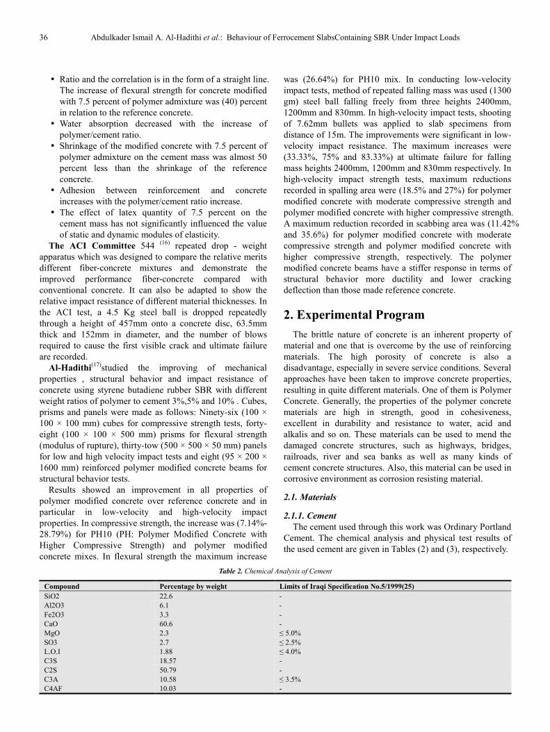
Table 2. Chemical Analysis of Cement
Limits of Iraqi Specification No.5/1999(25) Percentage by weight Compound
- 22.6 SiO2
- 6.1 Al2O3
- 3.3 Fe2O3
- 60.6 CaO
≤ 5.0% 2.3 MgO
≤ 2.5% 2.7 SO3
≤ 4.0% 1.88 L.O.I
- 18.57 C3S
- 50.79 C2S
≤ 3.5% 10.58 C3A
- 10.03 C4AF
International Journal o
Percentage by weightCompound
2.7 I.R
0.8 L.S.F
Physical properties
Fineness by Blaine
method (cm2/gm)
Autoclave expansion
%
Setting time
(Vicat apparatus) Initial setting
(minutes)
Final setting
(minutes)
Compressive strength 3 days (MPa) 7 days (MPa)
2.1.2. Fine Aggregate
Natural yellow sand passing through 2.36mm
No.7) and conforming to the B.S 882-
Table
Accumulated percentageSieve NO. 100 2.36
62.43 1.18
35.77 0.6
29.2 0.3
2.52 0.15
2.1.3. Mixing Water
Ordinary drinking water was used for mixing
for all specimens.
2.1.4. Polymer
Styrene Butadiene Rubber (SBR) is used
modifier in this study. Styrene Butadiene, an
polymer, is the copolymerized product of two
Styrene and Butadiene. Latex is typically
concrete in the form of a colloidal suspension
water .
This polymer is usually a milky-white fluid.
properties of SBR polymer is shown in Table
information is shown in Appendix. The polymer
used as a ratio by weight of cement of 3%, 5%
Table 5. Typical properties of SBR polymer
Description Properties No
White emulsion Appearance 1
1.02 ± 0.02 @ 25Specific Gravity 2 7 – 10.5 pH Value 3
Excellent Freeze/Thaw Resistance 4
Nil Chloride Content 5 Non-flammable Flammability 6
Can be used with
Portland cement Compatibility 7
2.1.5. Reinforcement
International Journal of Sustainable and Green Energy 2015; 4(3-1): 34-50
Limits of Iraqi Specification No.5/1999(25) weight
≤ 1.5%
0.66 – 1
Table 3. Physical analysis of cement
Limits of Iraqi Specification No.5/1999(25)Test result
2300 ≥ ≤ 0.8
4000
0.17
45≥ 600≤
150
225
15≥ 23≥
22.8
25
2.36mm (B.S. Sieve
-1992 grading
requirements (zone-2) was used in
specimens used in this study. Results
sand shown in Table (4).
Table 4 :Sieve analysis results of sand used
Limits of B.S 882-1992(18) percentage passing % 75-100
50-85
25-60
10-30
2-10
mixing and curing
used as polymer
an elastomeric
two monomers,
typically included in
suspension polymer in
fluid. The typical
Table (5), other
polymer (SBR) was
5% and 10%.
polymer (26)
25 ºC
with all types of
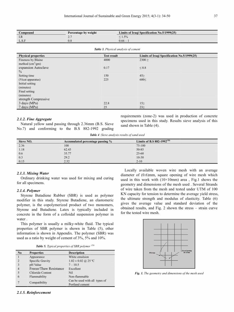
Locally available woven wire mesh
diameter of (0.6)mm, square opening
used in this work with (10×10mm)
geometry and dimensions of the mesh
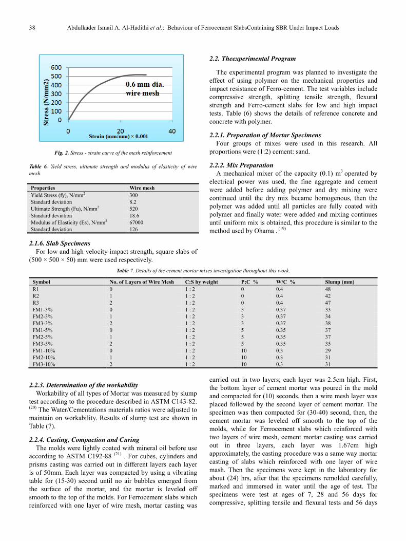
of wire taken from the mesh and tested
KN capacity for tension to determine
the ultimate strength and modulus
gives the average value and standard
obtained results, and Fig. 2 shown the
for the tested wire mesh.
Fig. 1. The geometry and dimensions
37
No.5/1999(25)
production of concrete
Results sieve analysis of this
mesh with an average
opening of wire mesh which
area , Fig.1 shows the
mesh used . Several Strands
tested under UTM of 100
the average yield stress,
of elasticity. Table (6)
standard deviation of the
the stress – strain curve
dimensions of the mesh used
38 Abdulkader Ismail A. Al-Hadithi et al.: Behaviour of Ferrocement SlabsContaining SBR Under Impact Loads
Fig. 2. Stress - strain curve of the mesh reinforcement
Table 6. Yield stress, ultimate strength and modulus of elasticity of wire
mesh
Wire mesh Properties
300 Yield Stress (fy), N/mm2
8.2 Standard deviation
520 Ultimate Strength (Fu), N/mm2
18.6 Standard deviation
67000 Modulus of Elasticity (Es), N/mm2
126 Standard deviation
2.1.6. Slab Specimens
For low and high velocity impact strength, square slabs of
(500 × 500 × 50) mm were used respectively.
2.2. Theexperimental Program
The experimental program was planned to investigate the
effect of using polymer on the mechanical properties and
impact resistance of Ferro-cement. The test variables include
compressive strength, splitting tensile strength, flexural
strength and Ferro-cement slabs for low and high impact
tests. Table (6) shows the details of reference concrete and
concrete with polymer.
2.2.1. Preparation of Mortar Specimens
Four groups of mixes were used in this research. All
proportions were (1:2) cement: sand.
2.2.2. Mix Preparation
A mechanical mixer of the capacity (0.1) m3
operated by
electrical power was used, the fine aggregate and cement
were added before adding polymer and dry mixing were
continued until the dry mix became homogenous, then the
polymer was added until all particles are fully coated with
polymer and finally water were added and mixing continues
until uniform mix is obtained, this procedure is similar to the
method used by Ohama . (19)
Table 7. Details of the cement mortar mixes investigation throughout this work.
Symbol No. of Layers of Wire Mesh C:S by weight P:C % W/C % Slump (mm)
R1 0 1 : 2 0 0.4 48
R2 1 1 : 2 0 0.4 42
R3 2 1 : 2 0 0.4 47
FM1-3% 0 1 : 2 3 0.37 33
FM2-3% 1 1 : 2 3 0.37 34
FM3-3% 2 1 : 2 3 0.37 38
FM1-5% 0 1 : 2 5 0.35 37
FM2-5% 1 1 : 2 5 0.35 37
FM3-5% 2 1 : 2 5 0.35 35
FM1-10% 0 1 : 2 10 0.3 29
FM2-10% 1 1 : 2 10 0.3 31
FM3-10% 2 1 : 2 10 0.3 31
2.2.3. Determination of the workability
Workability of all types of Mortar was measured by slump
test according to the procedure described in ASTM C143-82. (20)
The Water/Cementations materials ratios were adjusted to
maintain on workability. Results of slump test are shown in
Table (7).
2.2.4. Casting, Compaction and Curing
The molds were lightly coated with mineral oil before use
according to ASTM C192-88 (21)
. For cubes, cylinders and
prisms casting was carried out in different layers each layer
is of 50mm. Each layer was compacted by using a vibrating
table for (15-30) second until no air bubbles emerged from
the surface of the mortar, and the mortar is leveled off
smooth to the top of the molds. For Ferrocement slabs which
reinforced with one layer of wire mesh, mortar casting was
carried out in two layers; each layer was 2.5cm high. First,
the bottom layer of cement mortar was poured in the mold
and compacted for (10) seconds, then a wire mesh layer was
placed followed by the second layer of cement mortar. The
specimen was then compacted for (30-40) second, then, the
cement mortar was leveled off smooth to the top of the
molds, while for Ferrocement slabs which reinforced with
two layers of wire mesh, cement mortar casting was carried
out in three layers, each layer was 1.67cm high
approximately, the casting procedure was a same way mortar
casting of slabs which reinforced with one layer of wire
mash. Then the specimens were kept in the laboratory for
about (24) hrs, after that the specimens remolded carefully,
marked and immersed in water until the age of test. The
specimens were test at ages of 7, 28 and 56 days for
compressive, splitting tensile and flexural tests and 56 days
International Journal o
for impact test.
2.3. Testing Hardened Concrete
2.3.1. Compressive Strength Test
For compressive strength test a (100 × 100
concrete cubes were used according B.S. 1881
(1000KN) capacity ELE testing machine was
compressive test . the average compressive strength
cubes was recorded for each testing age (7,28 and
2.3.2. Splitting Tensile Strength Test
(100 × 200) mm concrete cylinders were
according to ASTM C192-88. (21)
The splitting
strength test was carried out according to ASTM
The load was applied by using (1000KN)
testing machine , the average of splitting tensile
three cylinders was recorded for each testing
56) days.
2.3.3. Flexural strength Test
A (100 × 100 × 500)mm concrete prisms
according to ASTM C192-88 .(21)
The test was
using two points load according to ASTM C78
ELE (50) KN capacity machine . Average modulus
of three prisms was obtained for each testing
56) days.
2.3.4. Impacttest
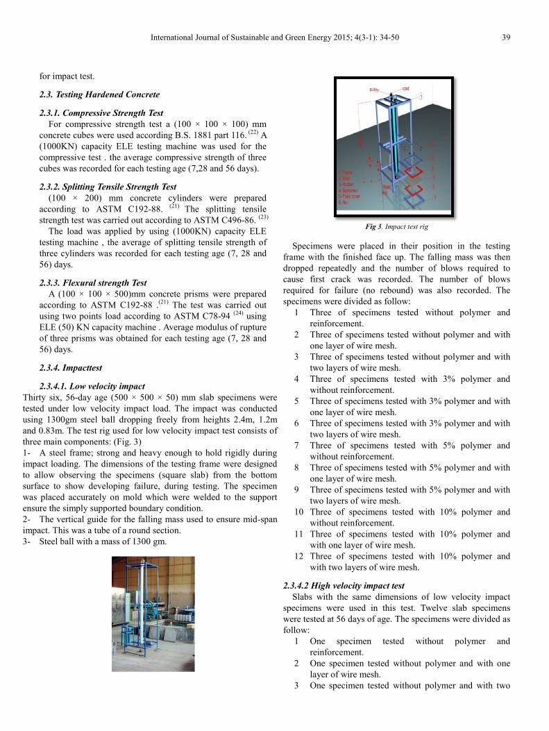
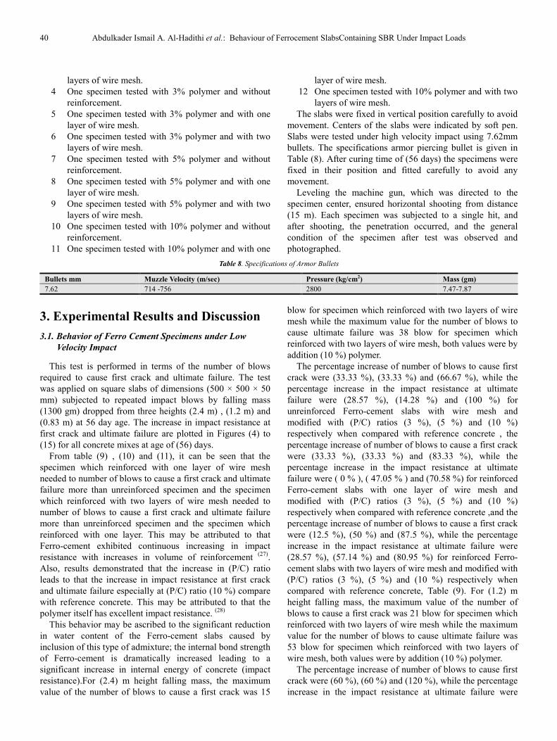
2.3.4.1. Low velocity impact
Thirty six, 56-day age (500 × 500 × 50) mm slab
tested under low velocity impact load. The impact
using 1300gm steel ball dropping freely from heights
and 0.83m. The test rig used for low velocity impact
three main components: (Fig. 3)
1- A steel frame; strong and heavy enough to hold
impact loading. The dimensions of the testing frame
to allow observing the specimens (square slab)
surface to show developing failure, during testing.
was placed accurately on mold which were welded
ensure the simply supported boundary condition.
2- The vertical guide for the falling mass used to
impact. This was a tube of a round section.
3- Steel ball with a mass of 1300 gm.
International Journal of Sustainable and Green Energy 2015; 4(3-1): 34-50
100 × 100) mm
1881 part 116. (22)
A
was used for the
strength of three
and 56 days).
were prepared
splitting tensile
ASTM C496-86. (23)
capacity ELE
tensile strength of
age (7, 28 and
were prepared
was carried out
C78-94 (24)
using
modulus of rupture
age (7, 28 and
slab specimens were
impact was conducted
heights 2.4m, 1.2m
impact test consists of
hold rigidly during
frame were designed
from the bottom
testing. The specimen
welded to the support
to ensure mid-span
Fig 3. Impact test rig
Specimens were placed in their
frame with the finished face up. The
dropped repeatedly and the number
cause first crack was recorded. The
required for failure (no rebound) was
specimens were divided as follow:
1 Three of specimens tested
reinforcement.
2 Three of specimens tested without
one layer of wire mesh.
3 Three of specimens tested without
two layers of wire mesh.
4 Three of specimens tested with
without reinforcement.
5 Three of specimens tested with
one layer of wire mesh.
6 Three of specimens tested with
two layers of wire mesh.
7 Three of specimens tested with
without reinforcement.
8 Three of specimens tested with
one layer of wire mesh.
9 Three of specimens tested with
two layers of wire mesh.
10 Three of specimens tested with
without reinforcement.
11 Three of specimens tested with
with one layer of wire mesh.
12 Three of specimens tested with
with two layers of wire mesh.
2.3.4.2 High velocity impact test
Slabs with the same dimensions of
specimens were used in this test. Twelve
were tested at 56 days of age. The specimens
follow:
1 One specimen tested without
reinforcement.
2 One specimen tested without
layer of wire mesh.
3 One specimen tested without
39
rig
position in the testing
The falling mass was then
number of blows required to
The number of blows
was also recorded. The
without polymer and
without polymer and with
without polymer and with
with 3% polymer and
with 3% polymer and with
with 3% polymer and with
with 5% polymer and
with 5% polymer and with
with 5% polymer and with
with 10% polymer and
with 10% polymer and
with 10% polymer and
of low velocity impact
Twelve slab specimens
specimens were divided as
without polymer and
polymer and with one
polymer and with two
40 Abdulkader Ismail A. Al-Hadithi et al.: Behaviour of Ferrocement SlabsContaining SBR Under Impact Loads
layers of wire mesh.
4 One specimen tested with 3% polymer and without
reinforcement.
5 One specimen tested with 3% polymer and with one
layer of wire mesh.
6 One specimen tested with 3% polymer and with two
layers of wire mesh.
7 One specimen tested with 5% polymer and without
reinforcement.
8 One specimen tested with 5% polymer and with one
layer of wire mesh.
9 One specimen tested with 5% polymer and with two
layers of wire mesh.
10 One specimen tested with 10% polymer and without
reinforcement.
11 One specimen tested with 10% polymer and with one
layer of wire mesh.
12 One specimen tested with 10% polymer and with two
layers of wire mesh.
The slabs were fixed in vertical position carefully to avoid
movement. Centers of the slabs were indicated by soft pen.
Slabs were tested under high velocity impact using 7.62mm
bullets. The specifications armor piercing bullet is given in
Table (8). After curing time of (56 days) the specimens were
fixed in their position and fitted carefully to avoid any
movement.
Leveling the machine gun, which was directed to the
specimen center, ensured horizontal shooting from distance
(15 m). Each specimen was subjected to a single hit, and
after shooting, the penetration occurred, and the general
condition of the specimen after test was observed and
photographed.
Table 8. Specifications of Armor Bullets
Mass (gm) Pressure (kg/cm2) Muzzle Velocity (m/sec) Bullets mm
7.47-7.87 2800 714 -756 7.62
3. Experimental Results and Discussion
3.1. Behavior of Ferro Cement Specimens under Low
Velocity Impact
This test is performed in terms of the number of blows
required to cause first crack and ultimate failure. The test
was applied on square slabs of dimensions (500 × 500 × 50
mm) subjected to repeated impact blows by falling mass
(1300 gm) dropped from three heights (2.4 m) , (1.2 m) and
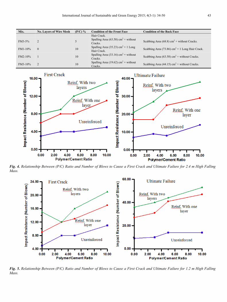
(0.83 m) at 56 day age. The increase in impact resistance at
first crack and ultimate failure are plotted in Figures (4) to
(15) for all concrete mixes at age of (56) days.
From table (9) , (10) and (11), it can be seen that the
specimen which reinforced with one layer of wire mesh
needed to number of blows to cause a first crack and ultimate
failure more than unreinforced specimen and the specimen
which reinforced with two layers of wire mesh needed to
number of blows to cause a first crack and ultimate failure
more than unreinforced specimen and the specimen which
reinforced with one layer. This may be attributed to that
Ferro-cement exhibited continuous increasing in impact
resistance with increases in volume of reinforcement (27)
.
Also, results demonstrated that the increase in (P/C) ratio
leads to that the increase in impact resistance at first crack
and ultimate failure especially at (P/C) ratio (10 %) compare
with reference concrete. This may be attributed to that the
polymer itself has excellent impact resistance. (28)
This behavior may be ascribed to the significant reduction
in water content of the Ferro-cement slabs caused by
inclusion of this type of admixture; the internal bond strength
of Ferro-cement is dramatically increased leading to a
significant increase in internal energy of concrete (impact
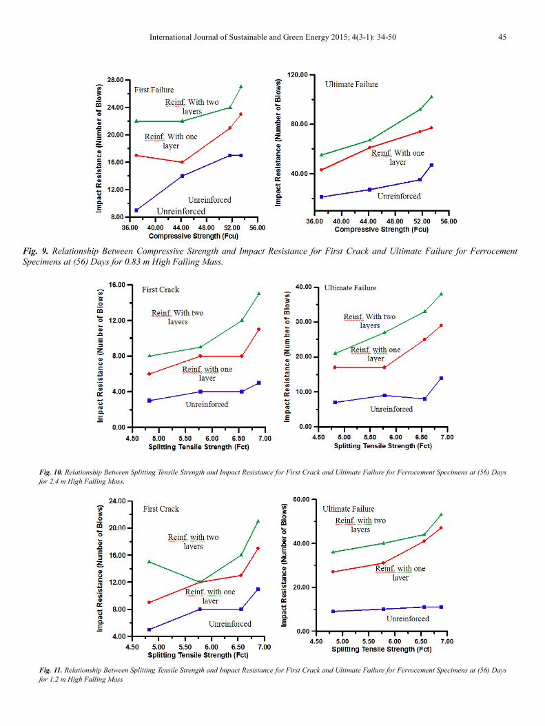
resistance).For (2.4) m height falling mass, the maximum
value of the number of blows to cause a first crack was 15
blow for specimen which reinforced with two layers of wire
mesh while the maximum value for the number of blows to
cause ultimate failure was 38 blow for specimen which
reinforced with two layers of wire mesh, both values were by
addition (10 %) polymer.
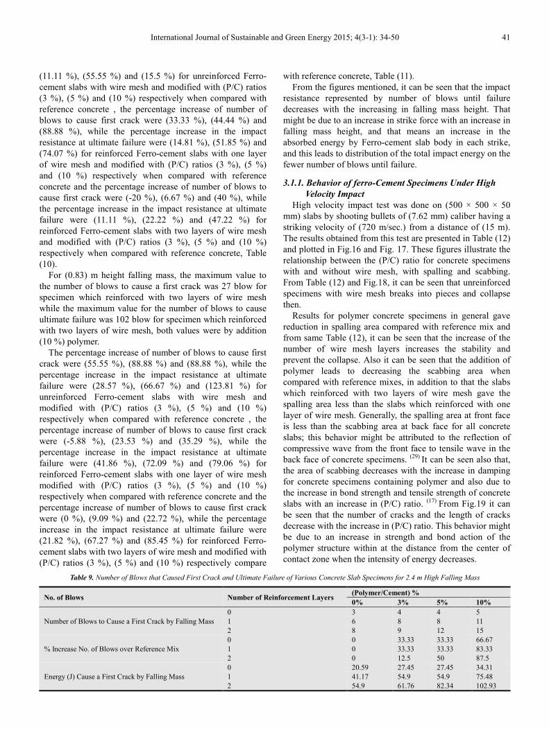
The percentage increase of number of blows to cause first
crack were (33.33 %), (33.33 %) and (66.67 %), while the
percentage increase in the impact resistance at ultimate
failure were (28.57 %), (14.28 %) and (100 %) for
unreinforced Ferro-cement slabs with wire mesh and
modified with (P/C) ratios (3 %), (5 %) and (10 %)
respectively when compared with reference concrete , the
percentage increase of number of blows to cause a first crack
were (33.33 %), (33.33 %) and (83.33 %), while the
percentage increase in the impact resistance at ultimate
failure were ( 0 % ), ( 47.05 % ) and (70.58 %) for reinforced
Ferro-cement slabs with one layer of wire mesh and
modified with (P/C) ratios (3 %), (5 %) and (10 %)
respectively when compared with reference concrete ,and the
percentage increase of number of blows to cause a first crack
were (12.5 %), (50 %) and (87.5 %), while the percentage
increase in the impact resistance at ultimate failure were
(28.57 %), (57.14 %) and (80.95 %) for reinforced Ferro-
cement slabs with two layers of wire mesh and modified with
(P/C) ratios (3 %), (5 %) and (10 %) respectively when
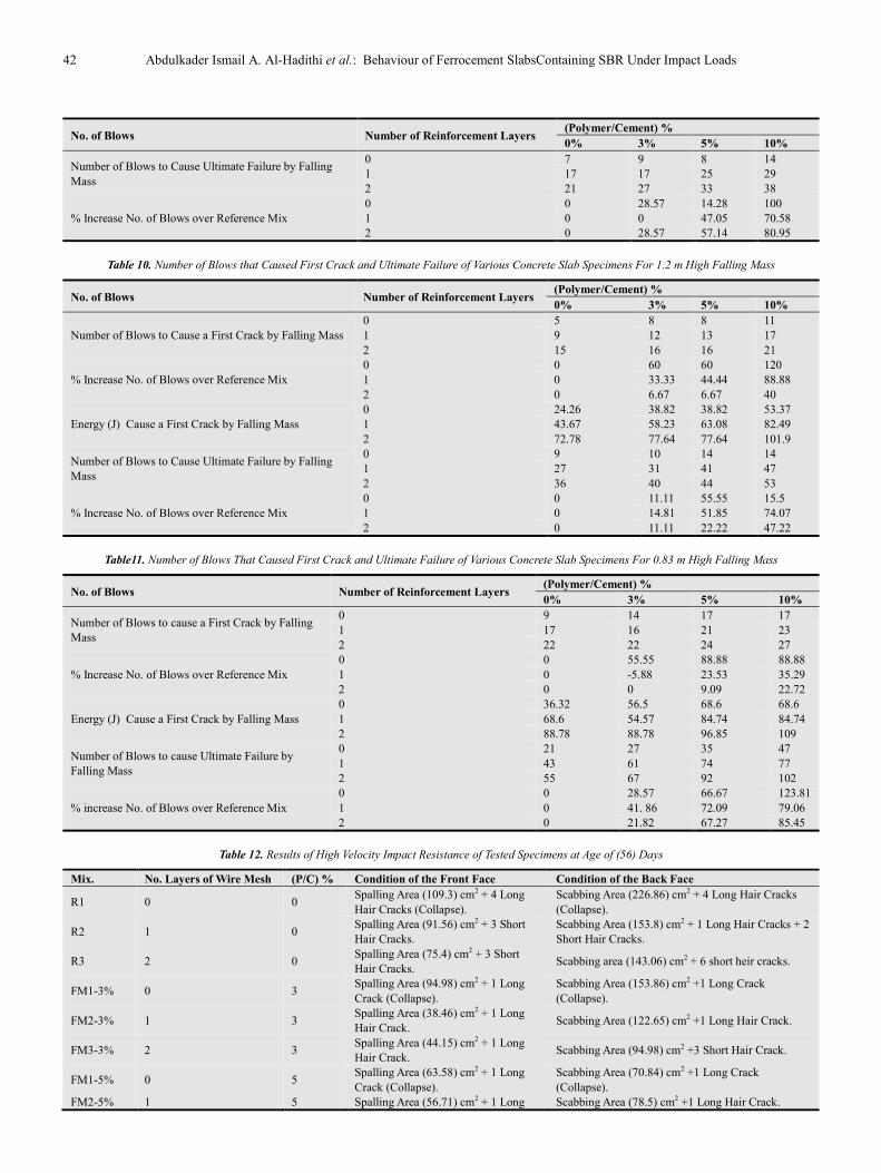
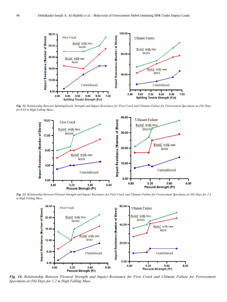
compared with reference concrete, Table (9). For (1.2) m
height falling mass, the maximum value of the number of
blows to cause a first crack was 21 blow for specimen which
reinforced with two layers of wire mesh while the maximum
value for the number of blows to cause ultimate failure was
53 blow for specimen which reinforced with two layers of
wire mesh, both values were by addition (10 %) polymer.
The percentage increase of number of blows to cause first
crack were (60 %), (60 %) and (120 %), while the percentage
increase in the impact resistance at ultimate failure were
International Journal of Sustainable and Green Energy 2015; 4(3-1): 34-50 41
(11.11 %), (55.55 %) and (15.5 %) for unreinforced Ferro-
cement slabs with wire mesh and modified with (P/C) ratios
(3 %), (5 %) and (10 %) respectively when compared with
reference concrete , the percentage increase of number of
blows to cause first crack were (33.33 %), (44.44 %) and
(88.88 %), while the percentage increase in the impact
resistance at ultimate failure were (14.81 %), (51.85 %) and
(74.07 %) for reinforced Ferro-cement slabs with one layer
of wire mesh and modified with (P/C) ratios (3 %), (5 %)
and (10 %) respectively when compared with reference
concrete and the percentage increase of number of blows to
cause first crack were (-20 %), (6.67 %) and (40 %), while
the percentage increase in the impact resistance at ultimate
failure were (11.11 %), (22.22 %) and (47.22 %) for
reinforced Ferro-cement slabs with two layers of wire mesh
and modified with (P/C) ratios (3 %), (5 %) and (10 %)
respectively when compared with reference concrete, Table
(10).
For (0.83) m height falling mass, the maximum value to
the number of blows to cause a first crack was 27 blow for
specimen which reinforced with two layers of wire mesh
while the maximum value for the number of blows to cause
ultimate failure was 102 blow for specimen which reinforced
with two layers of wire mesh, both values were by addition
(10 %) polymer.
The percentage increase of number of blows to cause first
crack were (55.55 %), (88.88 %) and (88.88 %), while the
percentage increase in the impact resistance at ultimate
failure were (28.57 %), (66.67 %) and (123.81 %) for
unreinforced Ferro-cement slabs with wire mesh and
modified with (P/C) ratios (3 %), (5 %) and (10 %)
respectively when compared with reference concrete , the
percentage increase of number of blows to cause first crack
were (-5.88 %), (23.53 %) and (35.29 %), while the
percentage increase in the impact resistance at ultimate
failure were (41.86 %), (72.09 %) and (79.06 %) for
reinforced Ferro-cement slabs with one layer of wire mesh
modified with (P/C) ratios (3 %), (5 %) and (10 %)
respectively when compared with reference concrete and the
percentage increase of number of blows to cause first crack
were (0 %), (9.09 %) and (22.72 %), while the percentage
increase in the impact resistance at ultimate failure were
(21.82 %), (67.27 %) and (85.45 %) for reinforced Ferro-
cement slabs with two layers of wire mesh and modified with
(P/C) ratios (3 %), (5 %) and (10 %) respectively compare
with reference concrete, Table (11).
From the figures mentioned, it can be seen that the impact
resistance represented by number of blows until failure
decreases with the increasing in falling mass height. That
might be due to an increase in strike force with an increase in
falling mass height, and that means an increase in the
absorbed energy by Ferro-cement slab body in each strike,
and this leads to distribution of the total impact energy on the
fewer number of blows until failure.
3.1.1. Behavior of ferro-Cement Specimens Under High
Velocity Impact
High velocity impact test was done on (500 × 500 × 50
mm) slabs by shooting bullets of (7.62 mm) caliber having a
striking velocity of (720 m/sec.) from a distance of (15 m).
The results obtained from this test are presented in Table (12)
and plotted in Fig.16 and Fig. 17. These figures illustrate the
relationship between the (P/C) ratio for concrete specimens
with and without wire mesh, with spalling and scabbing.
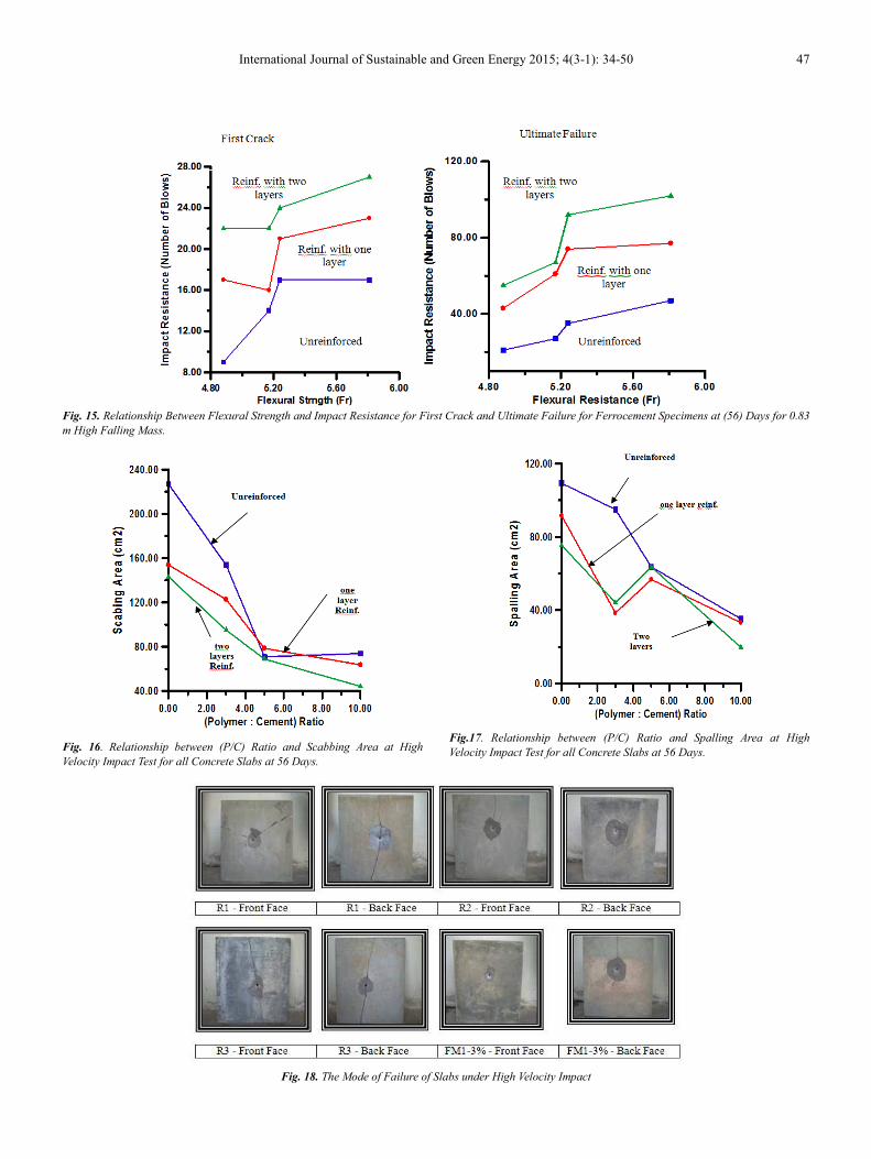
From Table (12) and Fig.18, it can be seen that unreinforced
specimens with wire mesh breaks into pieces and collapse
then.
Results for polymer concrete specimens in general gave
reduction in spalling area compared with reference mix and
from same Table (12), it can be seen that the increase of the
number of wire mesh layers increases the stability and
prevent the collapse. Also it can be seen that the addition of
polymer leads to decreasing the scabbing area when
compared with reference mixes, in addition to that the slabs
which reinforced with two layers of wire mesh gave the
spalling area less than the slabs which reinforced with one
layer of wire mesh. Generally, the spalling area at front face
is less than the scabbing area at back face for all concrete
slabs; this behavior might be attributed to the reflection of
compressive wave from the front face to tensile wave in the
back face of concrete specimens. (29)
It can be seen also that,
the area of scabbing decreases with the increase in damping
for concrete specimens containing polymer and also due to
the increase in bond strength and tensile strength of concrete
slabs with an increase in (P/C) ratio. (17)
From Fig.19 it can
be seen that the number of cracks and the length of cracks
decrease with the increase in (P/C) ratio. This behavior might
be due to an increase in strength and bond action of the
polymer structure within at the distance from the center of
contact zone when the intensity of energy decreases.
Table 9. Number of Blows that Caused First Crack and Ultimate Failure of Various Concrete Slab Specimens for 2.4 m High Falling Mass
No. of Blows Number of Reinforcement Layers (Polymer/Cement) %
0% 3% 5% 10%
Number of Blows to Cause a First Crack by Falling Mass
0 3 4 4 5
1 6 8 8 11
2 8 9 12 15
% Increase No. of Blows over Reference Mix
0 0 33.33 33.33 66.67
1 0 33.33 33.33 83.33
2 0 12.5 50 87.5
Energy (J) Cause a First Crack by Falling Mass
0 20.59 27.45 27.45 34.31
1 41.17 54.9 54.9 75.48
2 54.9 61.76 82.34 102.93
42 Abdulkader Ismail A. Al-Hadithi et al.: Behaviour of Ferrocement SlabsContaining SBR Under Impact Loads
No. of Blows Number of Reinforcement Layers (Polymer/Cement) %
0% 3% 5% 10%
Number of Blows to Cause Ultimate Failure by Falling
Mass
0 7 9 8 14
1 17 17 25 29
2 21 27 33 38
% Increase No. of Blows over Reference Mix 0 0 28.57 14.28 100
1 0 0 47.05 70.58
2 0 28.57 57.14 80.95
Table 10. Number of Blows that Caused First Crack and Ultimate Failure of Various Concrete Slab Specimens For 1.2 m High Falling Mass
No. of Blows Number of Reinforcement Layers (Polymer/Cement) %
0% 3% 5% 10%
Number of Blows to Cause a First Crack by Falling Mass
0 5 8 8 11
1 9 12 13 17
2 15 16 16 21
% Increase No. of Blows over Reference Mix
0 0 60 60 120
1 0 33.33 44.44 88.88
2 0 6.67 6.67 40
Energy (J) Cause a First Crack by Falling Mass 0 24.26 38.82 38.82 53.37
1 43.67 58.23 63.08 82.49
2 72.78 77.64 77.64 101.9
Number of Blows to Cause Ultimate Failure by Falling
Mass
0 9 10 14 14
1 27 31 41 47
2 36 40 44 53
% Increase No. of Blows over Reference Mix
0 0 11.11 55.55 15.5
1 0 14.81 51.85 74.07
2 0 11.11 22.22 47.22
Table11. Number of Blows That Caused First Crack and Ultimate Failure of Various Concrete Slab Specimens For 0.83 m High Falling Mass
No. of Blows Number of Reinforcement Layers (Polymer/Cement) %
0% 3% 5% 10%
Number of Blows to cause a First Crack by Falling
Mass
0 9 14 17 17
1 17 16 21 23
2 22 22 24 27
% Increase No. of Blows over Reference Mix
0 0 55.55 88.88 88.88
1 0 -5.88 23.53 35.29
2 0 0 9.09 22.72
Energy (J) Cause a First Crack by Falling Mass
0 36.32 56.5 68.6 68.6
1 68.6 54.57 84.74 84.74
2 88.78 88.78 96.85 109
Number of Blows to cause Ultimate Failure by
Falling Mass
0 21 27 35 47
1 43 61 74 77
2 55 67 92 102
% increase No. of Blows over Reference Mix
0 0 28.57 66.67 123.81 1 0 41. 86 72.09 79.06
2 0 21.82 67.27 85.45
Table 12. Results of High Velocity Impact Resistance of Tested Specimens at Age of (56) Days
Mix. No. Layers of Wire Mesh (P/C) % Condition of the Front Face Condition of the Back Face
R1 0 0 Spalling Area (109.3) cm2 + 4 Long
Hair Cracks (Collapse).
Scabbing Area (226.86) cm2 + 4 Long Hair Cracks
(Collapse).
R2 1 0 Spalling Area (91.56) cm2 + 3 Short
Hair Cracks.
Scabbing Area (153.8) cm2 + 1 Long Hair Cracks + 2
Short Hair Cracks.
R3 2 0 Spalling Area (75.4) cm2 + 3 Short
Hair Cracks. Scabbing area (143.06) cm2 + 6 short heir cracks.
FM1-3% 0 3 Spalling Area (94.98) cm2 + 1 Long
Crack (Collapse).
Scabbing Area (153.86) cm2 +1 Long Crack
(Collapse).
FM2-3% 1 3 Spalling Area (38.46) cm2 + 1 Long
Hair Crack. Scabbing Area (122.65) cm2 +1 Long Hair Crack.
FM3-3% 2 3 Spalling Area (44.15) cm2 + 1 Long
Hair Crack. Scabbing Area (94.98) cm2 +3 Short Hair Crack.
FM1-5% 0 5 Spalling Area (63.58) cm2 + 1 Long
Crack (Collapse).
Scabbing Area (70.84) cm2 +1 Long Crack
(Collapse).
FM2-5% 1 5 Spalling Area (56.71) cm2 + 1 Long Scabbing Area (78.5) cm2 +1 Long Hair Crack.
International Journal of Sustainable and Green Energy 2015; 4(3-1): 34-50 43
Mix. No. Layers of Wire Mesh (P/C) % Condition of the Front Face Condition of the Back Face
Hair Crack.
FM3-5% 2 5 Spalling Area (63.58) cm2 + without
Cracks. Scabbing Area (68.8) cm2 + without Cracks.
FM1-10% 0 10 Spalling Area (35.23) cm2 + 1 Long
Hair Crack. Scabbing Area (73.86) cm2 + 1 Long Hair Crack.
FM2-10% 1 10 Spalling Area (33.16) cm2 + without
Cracks. Scabbing Area (63.58) cm2 + without Cracks.
FM3-10% 2 10 Spalling Area (19.62) cm2 + without
Cracks. Scabbing Area (44.15) cm2 + without Cracks.
Fig. 4. Relationship Between (P/C) Ratio and Number of Blows to Cause a First Crack and Ultimate Failure for 2.4 m High Falling
Mass.
Fig. 5. Relationship Between (P/C) Ratio and Number of Blows to Cause a First Crack and Ultimate Failure for 1.2 m High Falling
Mass.
44 Abdulkader Ismail A. Al-Hadithi et al.: Behaviour of Ferrocement SlabsContaining SBR Under Impact Loads
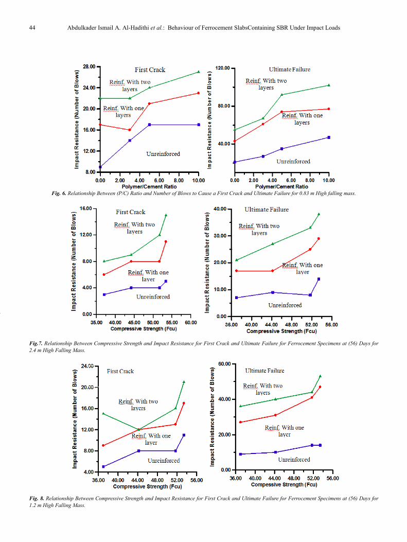
Fig. 6. Relationship Between (P/C) Ratio and Number of Blows to Cause a First Crack and Ultimate Failure for 0.83 m High falling mass.
Fig.7. Relationship Between Compressive Strength and Impact Resistance for First Crack and Ultimate Failure for Ferrocement Specimens at (56) Days for
2.4 m High Falling Mass.
Fig. 8. Relationship Between Compressive Strength and Impact Resistance for First Crack and Ultimate Failure for Ferrocement Specimens at (56) Days for
1.2 m High Falling Mass.
Unreinforced
International Journal of Sustainable and Green Energy 2015; 4(3-1): 34-50 45
Fig. 9. Relationship Between Compressive Strength and Impact Resistance for First Crack and Ultimate Failure for Ferrocement
Specimens at (56) Days for 0.83 m High Falling Mass.
Fig. 10. Relationship Between Splitting Tensile Strength and Impact Resistance for First Crack and Ultimate Failure for Ferrocement Specimens at (56) Days
for 2.4 m High Falling Mass.
Fig. 11. Relationship Between Splitting Tensile Strength and Impact Resistance for First Crack and Ultimate Failure for Ferrocement Specimens at (56) Days
for 1.2 m High Falling Mass
Unreinforced
46 Abdulkader Ismail A. Al-Hadithi et al.: Behaviour of Ferrocement SlabsContaining SBR Under Impact Loads
Fig. 12. Relationship Between SplittingTensile Strength and Impact Resistance for First Crack and Ultimate Failure for Ferrocement Specimens at (56) Days
for 0.83 m High Falling Mass.
Fig. 13. Relationship Between Flexural Strength and Impact Resistance for First Crack and Ultimate Failure for Ferrocement Specimens at (56) Days for 2.4
m High Falling Mass
Fig. 14. Relationship Between Flexural Strength and Impact Resistance for First Crack and Ultimate Failure for Ferrocement
Specimens at (56) Days for 1.2 m High Falling Mass.
International Journal of Sustainable and Green Energy 2015; 4(3-1): 34-50 47
Fig. 15. Relationship Between Flexural Strength and Impact Resistance for First Crack and Ultimate Failure for Ferrocement Specimens at (56) Days for 0.83
m High Falling Mass.
Fig. 16. Relationship between (P/C) Ratio and Scabbing Area at High
Velocity Impact Test for all Concrete Slabs at 56 Days.
Fig.17. Relationship between (P/C) Ratio and Spalling Area at High
Velocity Impact Test for all Concrete Slabs at 56 Days.
Fig. 18. The Mode of Failure of Slabs under High Velocity Impact
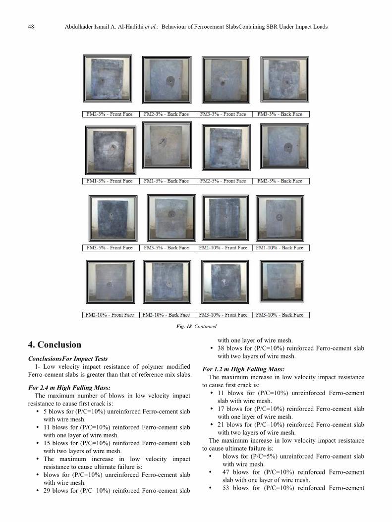
48 Abdulkader Ismail A. Al-Hadithi et al.: Behaviour of Ferrocement SlabsContaining SBR Under Impact Loads
Fig. 18. Continued
4. Conclusion
ConclusionsFor Impact Tests
1- Low velocity impact resistance of polymer modified
Ferro-cement slabs is greater than that of reference mix slabs.
For 2.4 m High Falling Mass:
The maximum number of blows in low velocity impact
resistance to cause first crack is:
� 5 blows for (P/C=10%) unreinforced Ferro-cement slab
with wire mesh.
� 11 blows for (P/C=10%) reinforced Ferro-cement slab
with one layer of wire mesh.
� 15 blows for (P/C=10%) reinforced Ferro-cement slab
with two layers of wire mesh.
� The maximum increase in low velocity impact
resistance to cause ultimate failure is:
� blows for (P/C=10%) unreinforced Ferro-cement slab
with wire mesh.
� 29 blows for (P/C=10%) reinforced Ferro-cement slab
with one layer of wire mesh.
� 38 blows for (P/C=10%) reinforced Ferro-cement slab
with two layers of wire mesh.
For 1.2 m High Falling Mass:
The maximum increase in low velocity impact resistance
to cause first crack is:
� 11 blows for (P/C=10%) unreinforced Ferro-cement
slab with wire mesh.
� 17 blows for (P/C=10%) reinforced Ferro-cement slab
with one layer of wire mesh.
� 21 blows for (P/C=10%) reinforced Ferro-cement slab
with two layers of wire mesh.
The maximum increase in low velocity impact resistance
to cause ultimate failure is:
� blows for (P/C=5%) unreinforced Ferro-cement slab
with wire mesh.
� 47 blows for (P/C=10%) reinforced Ferro-cement
slab with one layer of wire mesh.
� 53 blows for (P/C=10%) reinforced Ferro-cement
International Journal of Sustainable and Green Energy 2015; 4(3-1): 34-50 49
slab with two layers of wire mesh.
For 0.83m High Falling Mass:
The maximum increase in low velocity impact resistance
to cause first crack is:
� 17 blows for (P/C=5%) and (P/C=10%) unreinforced
Ferro-cement slab with wire mesh.
� 23 blows for (P/C=10%) reinforced Ferro-cement slab
with one layer of wire mesh.
� 27 blows for (P/C=10%) reinforced Ferro-cement slab
with two layers of wire mesh.
The maximum increase in low velocity impact resistance
to cause ultimate failure is:
� 47 blows for (P/C=10%) unreinforced Ferro-cement
slab with wire mesh.
� 77 blows for (P/C=10%) reinforced Ferro-cement slab
with one layer of wire mesh.
� 102 blows for (47.22 = 10%) reinforced Ferro-cement
slab with two layers of wire mesh.
2- Features of high-velocity impact resistance of polymer
modified Ferro-cement slabs can be stated as follows:
� Reduction in spalling area compared with reference
mix.
� Adding of SBR polymer resulted in prevention of the
appearance of cracks.
� Scabbing area was decreased in comparison with
reference mix when adding SBR polymer ranged
between 109.3 cm2
to 35.23 cm2 for unreinforced slab
concrete, from 91.56 cm2
to 33.16 cm2 for Ferro-
cement slab reinforced with one layer of wire mesh,
and from 75.4 cm2 to 19.62 cm
2 for Ferro-cement slab
reinforced with two layers of wire mesh.
3- Adding of SBR polymer and increasing number of
layers of reinforcement caused significant reduction in the
number of fragmentations flying out of the back face of
specimens.
Mode of Failure under Low Velocity Impact :
For slabs used in low velocity impact tests, the latex
modified Ferro-cement slabs failed with number of blows
more when compared with reference mix and the crack
started from center of top face and propagated on length and
width of specimens, and specimens was fractured into
separate pieces (ultimate failure) with number of blows more
than that in first crack stage.
For impact test in which the height of falling mass equals
(2.4) m, that un reinforced slabs with wire mesh reach to the
ultimate failure with number of blows near than number of
blows to cause a first crack . For low velocity impact tests
with falling mass failure of unmodified concrete was more
brittle than that latex of modified Ferro-cement slabs. The
slabs made of references mixes reach the first crack and
ultimate failure at number of blows less than that of the slabs
made of polymer modified concrete.
Behavior of Ferro-Cement specimens under High
Velocity Impact :
These figures illustrate the relationship between the (P/C)
ratio for concrete specimens with and without wire mesh,
with spalling and scabbing. and Plates , it can be seen
thatunreinforced specimens with wire mesh breaks into
pieces and collapse then. Results for polymer concrete
specimens in general gave reduction in spalling area
compared with reference mix , it can be seen that the
increase of the number of wire mesh layers increases the
stability and prevent the collapse.
Also it can be seen that the addition of polymer leads to
decreasing the scabbing area when compared with reference
mixes, in addition to that the slabs which reinforced with two
layers of wire mesh gave the spalling area less than the slabs
which reinforced with one layer of wire mesh.
Generally, the spalling area at front face is less than the
scabbing area at back face for all concrete slabs; this
behavior might be attributed to the reflection of compressive
wave from the front face to tensile wave in the back face of
concrete specimens. It can be seen also that, the area of
scabbing decreases with the increase in damping for concrete
specimens containing polymer and also due to the increase in
bond strength and tensile strength of concrete slabs with an
increase in (P/C) ratio.
From Plates, it can be seen that the number of cracks and
the length of cracks decrease with the increase in (P/C) ratio.
This behavior might be due to an increase in strength and
bond action of the polymer structure within at the distance
from the center of contact zone when the intensity of energy
decreases.
References
[1] Walks, B. R. .Testing and Test Methods for Ferrocement. Journal of Ferrocement. January 1986;16, No.1.
[2] Kalita, U.C., Nambiar, M.K.C., Borthakur, B.C., Baruah, P. Ferrocement Roof for Low-Cost Housing. July 1986. India Concrete Journal.
[3] Desayi, P., Viswanatha , C.S. , Hubli, G.K. Ferrocement Precast Elements for Roofing of Low-Cost Housing. Journal of Ferrocement. January1983. 13, No.1.
[4] Fukuchi, T., Ohama, Y. Manufacturing High Strength Concrete. International Symposium. SP-58, ACI. Detroit. 1978:215-224.
[5] Al- Rifaie, W.N., Aziz, A.A. Thin Ferrocement Bearing Walls. Journal of Ferrocement. July 1995. 25. No.3.
[6] Paul, B. K., Pama, R. P. Ferrocement, a Publication of International Ferrocement Information Center, Asian Institute of Technology, Bangkok, Thailand, Aug. 1978: 1-145.
[7] Al-Rifaie, W.N., Hassan, A.H. Structural Behavior of Thin Ferrocement One - way Bending Elements. Journal of Ferrocement. April 1994, Vol. 24: 115-126.
[8] ACI Committee 544. Measurement of Properties of Fiber Reinforced Concrete., ACI 544.2R. ACI Materials J., November-December. 85.No. 6.
50 Abdulkader Ismail A. Al-Hadithi et al.: Behaviour of Ferrocement SlabsContaining SBR Under Impact Loads
[9] Nillson, L. , Sahlin , S. Impact of a Steel Rod on a Reinforced Concrete Structures. SP-73. Dynamic Modeling of Concrete Structures, 1982.
[10] ACI Committee 544. Measurement of Properties of Fiber Reinforced Concrete. ACI 544.2R. ACI Materials J. November-December. 85, No.6.
[11] Nillson, L. , Sahlin , S. Impact of a Steel Rod on a Reinforced Concrete Structures. SP-73. Dynamic Modeling of Concrete Structures. 1982.
[12] Sauer, J. A., Nawy. E. G., Cook. C. Strength Improvements in Mortar and Concrete by Addition of Epoxies. IV International Conference on Materials Technology. Caracas. Venezuela. June-July. 1975: 802-809.
[13] Ohama, Y. Adhesion Durability of Polymer Modified Mortars. Application of Polymer Concrete. SP-69. ACI. Detroit 1981:193-205.
[14] Kuhlmann, A., Application of Styrene-Butadiene Latex Modified Concrete. Dec. 1987. Concrete International:48-53.
[15] Folic, R. J. , Randonjanin, V. S. Experimental Research on Polymer Modified Concrete. May-June, 1998. ACI Material Journal: 463-469.
[16] ACI Committee 544, “Measurement of Properties of Fiber Reinforced Concrete”, ACI 544, 2R, Manual of Concrete Practice, 1978.
[17] Al-Hadithi, Abdulkader Ismail. Flexural, Impact and Thermal Properties of Polymer Modified Concrete. March, 2005. Ph. D. Thesis. Building and Construction Department, University of Technology,
[18] British Standard Institute BSI, B.S.882: 1992.
[19] Ohama, Y. Recent Progress in Concrete Polymer Composites”, Advanced Cement Based Materials, New York. 1997, pp.31-40.
[20] ASTM CI43-89 .Standard Test Method for Slump of Hydraulic Cement Concrete. Annual Book of ASTM Standard, Philadeghia, Vol. 04-02, 1989:85-86.
[21] ASTM CI92-88 .Standard Practice for Making and Curing Test Specimens in the Laboratory”, Annual Book of ASTM Standard, Philadephia, Vol. 04-02, 1988:112-118.
[22] British Standard Institute BSI, B.S. 1881: Part 116: 1983. Method for Determination of Compressive Strength of Concrete Cubes.
[23] ASTM C496-86 .Standard Test Method for Splitting Tensile Strength of Cylindrical Concrete Specimens. 1989. Annual Book of ASTM Standard, Philadephia, Vol. 04-02, :259-262.
[24] ASTM 78-1994. Standard Test Method For Flexure Strength of Concrete {Using Simple Beam with Third-Point Loading}.1994. Annual Book of ASTM Standard, American Society for Testing and Materials. Philadephia, Pennsylvania. Vol.04-02.
[25] Iraqi standard specification, (1999),”Portland Cement”, No(5).
[26] Billmeyer, Fred W. , J.R. Textbook of Polymer Science. 1971. John Wielyb & Sons, U.S.A., 2nd Ed.
[27] Swamy, R.N., New Reinforced Concrete.1984, Vol.2. Surrey University Press,.
[28] Ohama, Y., Sugahara, T. Impact Resistance of Steel Fiber Reinforced Polymer Concrete . 1981. The Twenty Fourth Japan Congress on Materials Research. The Society of Material Science. Japan, :254-257.
[29] Shah, S.P. , Key, W.H. .Impact Resistance of Ferro- cement. Jun.1972. Journal of the Structural Division. Proceeding of the American Society of Civil Engineering.